- 2011 Jeep Wrangler Owners Manuals
- Jeep Wrangler Owners Manuals
- 2005 Jeep Wrangler Owners Manuals
- Jeep Wrangler Owners Manuals
- 2006 Jeep Wrangler Owners Manuals
- Jeep Wrangler Owners Manuals
- 2004 Jeep Wrangler Owners Manuals
- Jeep Wrangler Owners Manuals
- 2013 Jeep Wrangler Owners Manuals
- Jeep Wrangler Owners Manuals
- 2009 Jeep Wrangler Owners Manuals
- Jeep Wrangler Owners Manuals
- 2008 Jeep Wrangler Owners Manuals
- Jeep Wrangler Owners Manuals
- 2012 Jeep Wrangler Owners Manuals
- Jeep Wrangler Owners Manuals
- 2010 Jeep Wrangler Owners Manuals
- Jeep Wrangler Owners Manuals
- 2007 Jeep Wrangler Owners Manuals
- Jeep Wrangler Owners Manuals
- Download PDF Manual
-
cluster will light. To release the parking brake, pull up slightly, press the center button, then lower the lever completely. NOTE: The instrument cluster Brake Warning Light indicates only that the parking brake is applied. You must be sure the parking brake is fully applied before leaving the vehicle.
Parking Brake
Be sure the parking brake is firmly set when parked, and the shift lever is in the PARK position (automatic trans- mission), or REVERSE, or 1st gear (manual transmission). When parking on a hill, you should apply the parking brake before placing the shift lever in PARK, otherwise
the load on the transmission locking mechanism may make it difficult to move the shifter out of PARK.
WARNING!
• Always fully apply the parking brake when leav- ing your vehicle, or it may roll and cause damage or injury. Also, be certain to leave an automatic transmission in PARK, a manual transmission in REVERSE or 1st gear. Failure to do so may allow the vehicle to roll and cause damage or injury. • Never leave children alone in a vehicle. Leaving unattended children in a vehicle is dangerous for a number of reasons. A child or others could be seriously or fatally injured. Do not leave the key in the ignition. A child could operate power win- dows, other controls, or move the vehicle.
STARTING AND OPERATING 309
When parking on a hill, turn the front wheels toward the curb on a downhill grade and away from the curb on an uphill grade. The parking brake should always be applied whenever the driver is not in the vehicle.
ANTI-LOCK BRAKE SYSTEM The Anti-Lock Brake System (ABS) is designed to aid the driver in maintaining vehicle control under adverse braking conditions. The system operates with a separate computer to modulate hydraulic pressure to prevent wheel lock-up and help avoid skidding on slippery surfaces. All vehicle wheels and tires must be the same size and type and tires must be properly inflated to produce accurate signals for the computer.
310 STARTING AND OPERATING
WARNING!
Significant over or under-inflation of tires, or mixing sizes of tires or wheels on the vehicle can lead to loss of braking effectiveness.
The Anti-Lock Brake System conducts a low speed self- test at about 12 mph (20 km/h). If for any reason, your foot is on the brake when the vehicle reaches 12 mph (20
km/h), this check will be delayed until 25 mph (40
km/h). The Anti-Lock Brake System pump motor runs during the self-test, and during an ABS stop, to provide the regulated hydraulic pressure. The motor pump makes a low humming noise during operation, this is normal.During off-road use, loss of traction can temporarily defeat the system and cause the warning light to illumi- nate. Turn the ignition OFF and ON again to restore Anti-Lock Brake System function.
WARNING!
Pumping of the Anti-Lock Brakes will diminish their effectiveness and may lead to an accident. Pumping makes the stopping distance longer. Just press firmly on your brake pedal when you need to slow down or stop.
WARNING!
CAUTION!
STARTING AND OPERATING 311
• Anti-Lock Brake Systems (ABS) cannot prevent the natural laws of physics from acting on the vehicle, nor can it increase braking or steering efficiency beyond that afforded by the condition of the vehicle brakes and tires or the traction afforded.
• The ABS cannot prevent accidents,
including those resulting from excessive speed in turns, following another vehicle too closely, or hydro- planing. Only a safe, attentive, and skillful driver can prevent accidents. • The capabilities of an ABS-equipped vehicle must never be exploited in a reckless or dangerous manner which could jeopardize the user’s safety or the safety of others.
The Anti-Lock Brake System is subject to possible detrimental effects of electronic interference caused by improperly installed aftermarket radios or telephones.
NOTE: During severe braking conditions, a pulsing sensation may occur and a clicking noise will be heard. This is normal, the Anti-Lock Brake System is functioning.
indicating that
POWER STEERING The standard power steering system will give you good vehicle response and increased ease of maneuverability in tight spaces. The system will provide mechanical steering capability if power assist is lost.
312 STARTING AND OPERATING
If for some reason the power assist is interrupted, it will still be possible to steer your vehicle. Under these condi- tions, you will observe a substantial increase in steering effort, especially at very low vehicle speeds and during parking maneuvers. Increased noise levels at the end of the steering NOTE: wheel travel are considered normal and do not indicate that there is a problem with the power steering system. Upon initial start-up in cold weather, the power steering pump may make noise for a short amount of time. This is due to the cold, thick fluid in the steering system. This noise should be considered normal, and it does not in any way damage the steering system.
WARNING!
Continued operation with reduced power steering assist could pose a safety risk to yourself and others. Service should be obtained as soon as possible.
CAUTION!
Prolonged operation of the steering system at the end of the steering wheel travel will increase the steering fluid temperature and it should be avoided when possible. Damage to the power steering pump may occur.
TIRE SAFETY INFORMATION
Tire Markings
NOTE: • P(Passenger)-Metric tire sizing is based on U.S. design standards. P-Metric tires have the letter “P” molded into the sidewall preceding the size designation. Ex- ample: P215/65R15 95H.
STARTING AND OPERATING 313
• European Metric tire sizing is based on European design standards. Tires designed to this standard have the tire size molded into the sidewall beginning with the section width. The letter ⬙P⬙ is absent from this tire size designation. Example: 215/65R15 96H • LT(Light Truck)-Metric tire sizing is based on U.S. design standards. The size designation for LT-Metric tires is the same as for P-Metric tires except for the letters “LT” that are molded into the sidewall preced- ing the size designation. Example: LT235/85R16. • Temporary Spare tires are high pressure compact spares designed for temporary emergency use only. Tires designed to this standard have the letter “T” molded into the sidewall preceding the size designa- tion. Example: T145/80D18 103M. • High Flotation tire sizing is based on U.S. design standards and begins with the tire diameter molded into the sidewall. Example: 31x10.5 R15 LT.
314 STARTING AND OPERATING
Tire Sizing Chart
Size Designation:
EXAMPLE:
P = Passenger car tire size based on U.S. design standards ⴖ....blank....ⴖ = Passenger car tire based on European design standards LT = Light Truck tire based on U.S. design standards T = Temporary Spare tire 31 = Overall Diameter in Inches (in) 215 = Section Width in Millimeters (mm) 65 = Aspect Ratio in Percent (%)
—Ratio of section height to section width of tire
10.5 = Section Width in Inches (in) R = Construction Code
—⬙R⬙ means Radial Construction —⬙D⬙ means Diagonal or Bias Construction
15 = Rim Diameter in Inches (in)
STARTING AND OPERATING 315
Service Description:
95 = Load Index
EXAMPLE:
—A numerical code associated with the maximum load a tire can carry
H = Speed Symbol
—A symbol indicating the range of speeds at which a tire can carry a load corresponding to its load index under certain operating conditions —The maximum speed corresponding to the Speed Symbol should only be achieved un- der specified operating conditions (ie., tire pressure, vehicle loading, road conditions and posted speed limits)
Load Identification:
ⴖ....blank....ⴖ = Absence of any text on sidewall of the tire indicates a Standard Load (SL) Tire Extra Load (XL) = Extra Load (or Reinforced) Tire Light Load = Light Load Tire C,D,E = Load range associated with the maximum load a tire can carry at a specified pressure
Maximum Load — Maximum Load indicates the maximum load this tire is designed to carry Maximum Pressure — Maximum Pressure indicates the maximum permissible cold tire inflation pressure for this tire.
316 STARTING AND OPERATING
Tire Identification Number (TIN) The TIN may be found on one or both sides of the tire however the date code may only be on one side. Tires with white sidewalls will have the full TIN including date code
located on the white sidewall side of the tire. Look for the TIN on the outboard side of black sidewall tires as mounted on the vehicle. If the TIN is not found on the outboard side then you will find it on the inboard side of the tire.
EXAMPLE:
DOT MA L9 ABCD 0301
DOT = Department of Transportation
—This symbol certifies that the tire is in compliance with the U.S. Department of Transportation tire safety standards, and is approved for highway use.
MA = Code representing the tire manufacturing location (2 digits) L9 = Code representing the tire size (2 digits) ABCD = Code used by tire manufacturer (1 to 4 digits) 03 = Number representing the week in which the tire was manufactured (2 digits)
—03 means the 3rd week
01 = Number representing the year in which the tire was manufactured (2 digits)
—01 means the year 2001
—Prior to July 2000, tire manufacturers were only required to have 1 number to represent the year in which the tire was manufactured. Example: 031 could represent the 3rd week of 1981 or 1991.Tire Loading and Tire Pressure
Tire Placard Location
STARTING AND OPERATING 317
Tire Placard Location (Four-Door Models)
Tire Placard Location (Two-Door Models)
318 STARTING AND OPERATING
Tire and Loading Information Placard
Tire And Loading Information Placard
This placard tells you important information about the 1) number of people that can be carried in the vehicle 2) total weight your vehicle can carry 3) tire size designed for your vehicle
4) cold tire inflation pressures for the front, rear and spare tires. Loading The vehicle maximum load on the tire must not exceed the load carrying capacity of the tire on your vehicle. You will not exceed the tire’s load carrying capacity if you adhere to the loading conditions, tire size and cold tire inflation pressures specified on the Tire and Loading Information placard and the Vehicle Loading section of this manual. Refer to “Vehicle Loading” in this section. NOTE: Under a maximum loaded vehicle condition, gross axle weight ratings (GAWRs) for the front and rear axles must not be exceeded. For further information on GAWRs, vehicle loading and trailer towing. Refer to “Vehicle Loading” in this section. To determine the maximum loading conditions of your vehicle, locate the statement “The combined weight of occupants and cargo should never exceed XXX kg or XXX
lbs.” on the Tire and Loading Information placard. The combined weight of occupants, cargo/luggage and trailer tongue weight (if applicable) should never exceed the weight referenced here. Steps for Determining Correct Load Limit 1. Locate the statement “The combined weight of occu- pants and cargo should never exceed XXX pounds” on your vehicle’s placard. 2. Determine the combined weight of the driver and passengers that will be riding in your vehicle. 3. Subtract the combined weight of the driver and pas- sengers from XXX kilograms or XXX pounds. 4. The resulting figure equals the available amount of cargo and luggage load capacity. For example, if “XXX” amount equals 1,400 lbs (635 kg) and there will be five 150 lbs (68 kg) passengers in your vehicle, the amount of available cargo and luggage load capacity is 650 lbs (295
kg) (since 5 x 150 = 750, and 1400 – 750 = 650 lbs (295 kg).STARTING AND OPERATING 319
5. Determine the combined weight of luggage and cargo being loaded on the vehicle. That weight may not safely exceed the available cargo and luggage load capacity calculated in step 4. 6. If your vehicle will be towing a trailer, the load from your trailer will be transferred to your vehicle. Consult this manual to determine how this reduces the available cargo and luggage load capacity of your vehicle. NOTE: The following table shows examples on how to calculate total load, cargo/luggage and towing capacities of your vehicle with varying seating configurations and number and size of occupants. This table is for illustra- tion purposes only and may not be accurate for the seating and load carry capacity of your vehicle. NOTE: For the following example the combined weight of occupants and cargo should never exceed 865 lbs (392
kg).320 STARTING AND OPERATING
WARNING!
Safety
STARTING AND OPERATING 321
Overloading of your tires is dangerous. Overloading can cause tire failure, affect vehicle handling, and increase your stopping distance. Use tires of the recommended load capacity for your vehicle. Never overload them.
TIRES — GENERAL INFORMATION
Tire Pressure Proper tire inflation pressure is essential to the safe and satisfactory operation of your vehicle. Three primary areas are affected by improper tire pressure:
WARNING!
Improperly inflated tires are dangerous and can cause accidents. • Under-inflation increases tire flexing and can result in tire failure. • Over-inflation reduces a tire’s ability to cushion shock. Objects on the road and chuck holes can cause damage that results in tire failure. • Unequal tire pressures can cause steering problems. You could lose control of your vehicle. • Over-inflated or under-inflated tires can affect vehicle handling and can fail suddenly, resulting in loss of vehicle control. • Unequal tire pressures from one side of the vehicle to the other can cause the vehicle to drift to the right or left. Always drive with each tire properly inflated.
Tire Inflation Pressures
322 STARTING AND OPERATING
Economy Improper inflation pressures can cause uneven wear patterns to develop across the tire tread. These abnormal wear patterns will reduce tread life resulting in a need for earlier tire replacement. Under-inflation also increases tire rolling resistance and results in higher fuel consump- tion. Ride Comfort and Vehicle Stability Proper tire inflation contributes to a comfortable ride. Over-inflation produces a jarring and uncomfortable ride.
Tire Placard Location (Two-Door Models)
STARTING AND OPERATING 323
CAUTION!
After inspecting or adjusting the tire pressure always reinstall the valve stem cap. This will prevent mois- ture and dirt from entering the valve stem, which could damage the Tire Pressure Monitoring Sensor.
Inflation pressures specified on the placard are always “cold tire inflation pressure.” Cold tire inflation pressure is defined as the tire pressure after the vehicle has not been driven for at least three hours, or driven less than 1
mi (1 km) after a three hour period. The cold tire inflation pressure must not exceed the maximum inflation pres- sure molded into the tire side wall. Check tire pressures more often if subject to a wide range of outdoor temperatures, as tire pressures vary with temperature changes.Tire Placard Location (Four-Door Models)
Tire pressure should be checked and adjusted as well as inspecting for signs of tire wear or visible damage, at least once a month. Use a good quality pocket-type gauge to check tire pressure. Do not make a visual judgement when determining proper inflation. Radial tires may look properly inflated even when they are under inflated.
324 STARTING AND OPERATING
Tire pressures change by approximately 1 psi (7 kPa) per 12° F (7° C) of air temperature change. Keep this in mind when checking tire pressure inside a garage especially in the winter. Example: If garage temperature = 68° F (20° C) and the outside temperature = 32° F (0° C) then the cold tire inflation pressure should be increased by 3 psi (21 kPa), which equals 1 psi (7 kPa) for every 12° F (7° C) for this outside temperature condition. Tire pressure may increase from 2 to 6 psi (13 to 40 kPa) during operation. DO NOT reduce this normal pressure buildup or your tire pressure will be too low. Tire Pressures for High-Speed Operation The manufacturer advocates driving at safe speeds within posted speed limits. Where speed limits or condi- tions are such that the vehicle can be driven at high speeds, maintaining correct tire inflation pressure is very important. Increased tire pressure and reduced vehicle
loading may be required for high-speed vehicle opera- tion. Refer to original equipment or an authorized tire dealer for recommended safe operating speeds, loading and cold tire inflation pressures.
WARNING!
High speed driving with your vehicle under load is dangerous. The added strain on your tires could cause them to fail. You could have a serious accident. Do not drive a vehicle loaded to maximum capacity at continuous speeds above 75 mph (120 km/h).
Radial-Ply Tires
WARNING!
Combining radial ply tires with other types of tires on your vehicle will cause your vehicle to handle poorly. The instability could cause an accident. Al- ways use radial tires in sets of four. Never combine them with other types of tires.
Cuts and punctures in radial tires are repairable only in the tread area because of sidewall flexing. Consult your authorized dealer for radial tire repairs.
STARTING AND OPERATING 325
Tire Spinning When stuck in mud, sand, snow, or ice conditions, do not spin your vehicle’s wheels above 35 mph (55 km/h).
WARNING!
Fast spinning tires can be dangerous. Forces gener- ated by excessive wheel speeds may cause tire dam- age or failure. A tire could explode and injure some- one. Do not spin your vehicle’s wheels faster than 35
mph (55 km/h) when you are stuck, and do not let anyone near a spinning wheel no matter what the speed.326 STARTING AND OPERATING
Tread Wear Indicators Tread wear indicators are in the original equipment tires to help you in determining when your tires should be replaced.
These indicators are molded into the bottom of the tread grooves and will appear as bands when the tread depth becomes 1/16 inch (2 mm). When the indicators appear in two or more adjacent grooves, the tire should be replaced. Many states have laws requiring tire replacement at this point. Life of Tire The service life of a tire is dependent upon varying factors including but not limited to: • Driving style • Tire pressure • Distance driven
WARNING!
Tires and spare tire should be replaced after six years, regardless of the remaining tread. Failure to follow this warning can result in sudden tire failure. You could lose control and have an accident resulting in serious injury or death.
Keep unmounted tires in a cool, dry place with as little exposure to light as possible. Protect tires from contact with oil, grease and gasoline.
STARTING AND OPERATING 327
Replacement Tires The tires on your new vehicle provide a balance of many characteristics. They should be inspected regularly for wear and correct cold tire inflation pressure. The manu- facturer strongly recommends that you use tires equiva- lent to the originals in size, quality and performance when replacement is needed (see the paragraph on tread wear indicators). Refer to the Tire and Loading Informa- tion placard for the size designation of your tire. The service description and load identification will be found on the original equipment tire. Failure to use equivalent replacement tires may adversely affect the safety, han- dling, and ride of your vehicle. We recommend that you contact your original equipment or an authorized tire dealer with any questions you may have on tire specifi- cations or capability.
328 STARTING AND OPERATING
WARNING!
• Do not use a tire, wheel size or rating other than that specified for your vehicle. Some combinations of unapproved tires and wheels may change suspension dimensions and performance characteristics, result- ing in changes to steering, handling, and braking of your vehicle. This can cause unpredictable handling and stress to steering and suspension components. You could lose control and have an accident resulting in serious injury or death. Use only the tire and wheel sizes with load ratings approved for your vehicle. • Never use a tire with a smaller load index or capacity, other than what was originally equipped on your vehicle. Using a tire with a smaller load index could result in tire overloading and failure. You could lose control and have an accident. • Failure to equip your vehicle with tires having ad- equate speed capability can result in sudden tire failure and loss of vehicle control.
CAUTION!
Replacing original tires with tires of a different size may result in false speedometer and odometer readings.
Alignment and Balance Poor suspension alignment may result in: • Fast tire wear. • Uneven tire wear, such as feathering and one-sided • Vehicle pull to right or left. Tires may also cause the vehicle to pull left or right. Alignment will not correct this problem. See your autho- rized dealer for proper diagnosis.
wear.
Improper alignment will not cause vehicle vibration. Vibration may be a result of tire and wheel out-of- balance. Proper balancing will reduce vibration and avoid tire cupping and spotty wear.
TIRE CHAINS Install chains on rear tires only. Tire chains may be installed on all models except the Sahara and Rubicon. Follow these recommendations to guard against damage and excessive tire and chain wear: • Use chains on P225/75R16 tires only. P245/75R16, P255/75R17, P255/70R18, and LT255/75R17 tires do not provide adequate clearance. • Use SAE class “S” tire chains or traction devices only. • Chains must be the proper size for the vehicle, as • Follow tire chain manufacturer’s instructions for
recommended by the chain manufacturer.
mounting chains.
STARTING AND OPERATING 329
driving.
• Install chains snugly and tighten after 0.6 mi (1 km) of • Do not exceed 30 mph (48 km/h). • Drive cautiously, avoiding large bumps, potholes and
extreme driving maneuvers.
TIRE ROTATION RECOMMENDATIONS Tires on the front and rear axles of vehicles operate at different loads and perform different steering, handling, and braking functions. For these reasons, they wear at unequal rates, and develop irregular wear patterns. These effects can be reduced by timely rotation of tires. The benefits of rotation are especially worthwhile with aggressive tread designs such as those on On/Off Road type tires. Rotation will increase tread life, help to main- tain mud, snow, and wet traction levels, and contribute to a smooth, quiet ride.
330 STARTING AND OPERATING
Follow the recommended tire rotation frequency for your type of driving. Refer to the “Maintenance Schedule” in Section 8 of this manual. More frequent rotation is permissible if desired. The reasons for any rapid or unusual wear should be corrected prior to rotation being performed. The suggested rotation method is the “forward-cross” shown in the following diagram.
TIRE PRESSURE MONITOR SYSTEM (TPMS) The Tire Pressure Monitoring System (TPMS) will warn the driver of a low tire pressure based on the vehicle recommended cold placard pressure. The tire pressure will vary with temperature by about 1
psi (6.9 kPa) for every 12°F (6.5°C). This means that when the outside temperature decreases, the tire pressure will decrease. Tire pressure should always be set based on cold inflation tire pressure. This is defined as the tire pressure after a vehicle has not been driven for more than three hours, or driven less than 1 mi (1 km) after a three hour period. Refer to the “Tires — General Informa- tion” in this section for information on how to properly inflate the vehicle’s tires. The tire pressure will also increase as the vehicle is driven, this is normal and there should be no adjustment for this increased pressure.The TPMS will warn the driver of a low tire pressure if the tire pressure falls below the low pressure warning threshold for any reason, including low temperature effects, or natural pressure loss through the tire. The TPMS will continue to warn the driver of low tire pressure as long as the condition exists, and will not turn off until the tire pressure is at or above recommended cold placard pressure. Once the Tire Pressure Monitoring Telltale Light has been illuminated, the tire pressure must be increased to the recommended cold placard pressure in order for the Tire Pressure Monitoring Telltale Light to be turned off. The system will automatically update and the Tire Pressure Monitoring Telltale Light will extin- guish once the updated tire pressures have been received. The vehicle may need to be driven for up to 10 minutes above 15 mph (25 km/h) to receive this information.
STARTING AND OPERATING 331
For example, your vehicle may have a recommended cold (parked for more than three hours) air pressure of 35
psi (241 kPa). If the ambient temperature is 68°F (20°C) and the measured tire pressure is 30 psi (207 kPa), a temperature drop to 20°F (-7°C) will decrease the tire pressure to approximately 26 psi (179 kPa). This tire pressure is sufficiently low enough to turn ON the Tire Pressure Monitoring Telltale Light. Driving the vehicle may cause the tire pressure to rise to approximately 30
psi (207 kPa), but the Tire Pressure Monitoring Telltale Light will still be ON. In this situation, the Tire Pressure Monitoring Telltale Light will turn OFF only after the tires have been inflated to the vehicle’s recommended cold placard pressure value.332 STARTING AND OPERATING
CAUTION!
CAUTION!
The TPMS has been optimized for the original equipment tires and wheels. TPMS pressures have been established for the tire size equipped on your vehicle. Undesirable system operation or sensor damage may result when using replacement equip- ment that is not of the same size, type, and/or style. Aftermarket wheels can cause sensor damage. Do not use aftermarket tire sealants or balance beads if your vehicle is equipped with a TPMS, as damage to the sensors may result.
After inspecting or adjusting the tire pressure always reinstall the valve stem cap. This will prevent mois- ture and dirt from entering the valve stem, which could damage the Tire Pressure Monitoring Sensor.
NOTE: • The TPMS is not intended to replace normal tire care and maintenance, nor to provide warning of a tire failure or condition. • The TPMS should not be used as a tire pressure gauge • Driving on a significantly under-inflated tire causes the tire to overheat and can lead to tire failure. Under-inflation also reduces fuel efficiency and tire tread life, and may affect the vehicle’s handling and stopping ability.
while adjusting your tire pressure.
• The TPMS is not a substitute for proper tire mainte- nance, and it is the driver’s responsibility to maintain correct tire pressure, even if under-inflation has not reached the level to trigger illumination of the Tire Pressure Monitoring Telltale Light. • Seasonal temperature changes will affect tire pressure, and the TPM System will monitor the actual tire pressure in the tire.
Base System The Tire Pressure Monitor System (TPMS) uses wireless technology with wheel rim-mounted electronic sensors to monitor tire pressure levels. Sensors, mounted to each wheel as part of the valve stem, transmit tire pressure readings to the Receiver Module. It is particularly important, for you to check the NOTE: tire pressure in all of your tires regularly and to maintain the proper pressure.
STARTING AND OPERATING 333
The Tire Pressure Monitor System (TPMS) consists of the following components: • Receiver Module • Four Tire Pressure Monitoring Sensors • Tire Pressure Monitoring Telltale Light A tire pressure monitoring sensor is located in the spare wheel if the vehicle is equipped with a matching full size spare wheel and tire assembly. The matching full size spare tire can be used in place of any of the four road tires. A low spare tire will not cause the Tire Pressure Monitoring Telltale Light to illuminate or the chime to sound.
The Tire Pressure Monitoring Telltale Light will illuminate in the instrument cluster, and an au- dible chime will be activated when one or more of the four active road tire pressures are low. Should this occur, you should stop as soon as possible, check the
334 STARTING AND OPERATING
inflation pressure of each tire on your vehicle, and inflate each tire to the vehicle’s recommended cold placard pressure value. The system will automatically update and the Tire Pressure Monitoring Telltale Light will extinguish once the updated tire pressures have been received. The vehicle may need to be driven for up to 10
minutes above 15 mph (25 km/h) to receive this infor- mation. The Tire Pressure Monitoring Telltale Light will flash on and off for 75 seconds, and will remain on solid when a system fault is detected. The system fault will also sound a chime. If the ignition key is cycled, this sequence will repeat, providing the system fault still exists. A system fault can occur by any of the following scenarios: 1. Jamming due to electronic devices or driving next to facilities emitting the same Radio Frequencies as the TPM sensors. 2. Installing some form of aftermarket window tinting that affects radio wave signals.3. Lots of snow or ice around the wheels or wheel housings. 4. Using tire chains on the vehicle. 5. Using wheels/tires not equipped with TPM sensors. If your vehicle is equipped with a matching NOTE: full-size spare wheel and tire assembly, it has a tire pressure monitoring sensor, and can be monitored by the Tire Pressure Monitoring System (TPMS). In the event that the matching full-size spare tire is swapped with a low pressure road tire, the next ignition key cycle will still show the Tire Pressure Monitoring Telltale Light to be ON, and a chime to sound. Driving the vehicle for up to 10 minutes above 15 mph (25 km/h) will turn OFF the Tire Pressure Monitoring Telltale Light as long as none of the road tires are below the low pressure warning thresh- old.
If your vehicle is not equipped with a matching NOTE: full-size spare wheel and tire assembly, it does not have a tire pressure monitoring sensor in the spare tire. The TPMS will not be able to monitor the tire pressure. If you install the spare tire in place of a road tire that has a pressure below the low-pressure warning limit, upon the next ignition key cycle, a chime will sound and the Tire Pressure Monitoring Telltale Light will turn ON. After driving the vehicle for up to 10 minutes above 15 mph (25
km/h), the Tire Pressure Monitoring Telltale Light will flash on and off for 75 seconds and then remain on solid. For each subsequent ignition key cycle, a chime will sound and the Tire Pressure Monitoring Telltale Light will flash on and off for 75 seconds and then remain on solid. Once you repair or replace the original road tire, and reinstall it on the vehicle in place of the spare tire, the TPMS will update automatically and the Tire Pressure Monitoring Telltale Light will turn OFF, as long as no tire pressure is below the low-pressure warning limit in anySTARTING AND OPERATING 335
of the four active road tires. The vehicle may need to be driven for up to 10 minutes above 15 mph (25 km/h) in order for the TPMS to receive this information. General Information This device complies with part 15 of the FCC rules and RSS 210 of Industry Canada. Operation is subject to the following conditions: • This device may not cause harmful interference. • This device must accept any interference received, including interference that may cause undesired op- eration.
The tire pressure sensors are covered under one of the following licenses:
United States . . . . . . . . . . . . . . . . . . . . . KR5S120123
Canada . . . . . . . . . . . . . . . . . . . . . . . . 2671-S120123336 STARTING AND OPERATING
FUEL REQUIREMENTS
All engines (except 5.7L engines) are de- signed to meet all emissions regulations and provide excellent fuel economy and performance when using high quality un- leaded “regular” gasoline having an oc- tane rating of 87. The use of premium gasoline is not recommended. Under normal conditions, the use of premium gasoline will not provide a benefit over high quality regular gasoline, and in some circum- stances may result in poorer performance. Light spark knock at low engine speeds is not harmful to your engine. However, continued heavy spark knock at high speeds can cause damage and immediate service is required.
Poor quality gasoline can cause problems such as hard starting, stalling and hesitations. If you experience these symptoms, try another brand of gasoline before consid- ering service for the vehicle. Over 40 auto manufacturer’s worldwide have issued and endorsed consistent gasoline specifications (the World- wide Fuel Charter, WWFC) to define fuel properties necessary to deliver enhanced emissions, performance, and durability for your vehicle. The manufacturer recom- mends the use of gasoline that meets the WWFC speci- fications if they are available. Reformulated Gasoline Many areas of the country require the use of cleaner burning gasoline referred to as “Reformulated Gasoline.” Reformulated gasoline contains oxygenates, and are spe- cifically blended to reduce vehicle emissions and im- prove air quality.
The manufacturer supports the use of reformulated gaso- line. Properly blended reformulated gasoline will pro- vide excellent performance and durability for the engine and fuel system components. Gasoline/Oxygenate Blends Some fuel suppliers blend unleaded gasoline with oxy- genates such as 10% ethanol, MTBE, and ETBE. Oxygen- ates are required in some areas of the country during the winter months to reduce carbon monoxide emissions. Fuels blended with these oxygenates may be used in your vehicle.
CAUTION!
DO NOT use gasolines containing Methanol. Use of these blends may result in starting and drivability problems and may damage critical fuel system components.
STARTING AND OPERATING 337
Problems that result from using methanol/gasoline blends are not the responsibility of the manufacturer. While MTBE is an oxygenate made from Methanol, it does not have the negative effects of Methanol. MMT In Gasoline MMT is a manganese containing metallic additive that is blended into some gasoline to increase the octane num- ber. Gasoline blended with MMT offers no performance advantage beyond gasoline of the same octane number without MMT. Gasoline blended with MMT has shown to reduce sparkplug life and reduce emission system performance in some vehicles. The manufacturer recom- mends that gasoline without MMT be used in your vehicle. The MMT content of gasoline may not be indi- cated on the gasoline pump, therefore, you should ask your gasoline retailer if the gasoline contains MMT.
338 STARTING AND OPERATING
and California-
It is even more important to look for gasoline without MMT in Canada, because MMT can be used at levels higher than those allowed in the United States. MMT is prohibited in Federal reformulated gasoline. Materials Added To Fuel All gasoline sold in the United States is required to contain effective detergent additives. Use of additional detergents or other additives are not needed under normal conditions and would result in additional cost. Therefore you should not have to add anything to the fuel.
Fuel System Cautions
CAUTION!
Follow these guidelines to maintain your vehicle’s performance:
• The use of leaded gasoline is prohibited by Federal law. Using leaded gasoline can impair engine perfor- mance, and damage the emission control system. • An out-of-tune engine, or certain fuel or ignition malfunctions, can cause the catalytic converter to overheat. If you notice a pungent burning odor or some light smoke, your engine may be out of tune or malfunctioning and may require immediate service. Contact your authorized dealer for service assistance.
• The use of fuel additives which are now being sold as octane enhancers is not recommended. Most of these products contain high concentrations of methanol. Fuel system damage or vehicle performance problems resulting from the use of such fuels or additives is not the responsibility of the manufacturer.
Intentional tampering with emissions control in civil penalties being assessed
NOTE: systems can result against you. Carbon Monoxide Warnings
WARNING!
Carbon monoxide (CO) in exhaust gases is deadly. Follow the precautions below to prevent carbon monoxide poisoning:
STARTING AND OPERATING 339
• Do not inhale exhaust gases. They contain carbon monoxide, a colorless and odorless gas which can kill. Never run the engine in a closed area, such as a garage, and never sit in a parked vehicle with the engine running for an extended period. If the vehicle is stopped in an open area with the engine running for more than a short period, adjust the ventilation system to force fresh, outside air into the vehicle. • Guard against carbon monoxide with proper mainte- nance. Have the exhaust system inspected every time the vehicle is raised. Have any abnormal conditions repaired promptly. Until repaired, drive with all side windows fully open. • Keep the swing gate closed when driving your vehicle to prevent carbon monoxide and other poisonous exhaust gases from entering the vehicle.
340 STARTING AND OPERATING
ADDING FUEL
Fuel Filler Cap (Gas Cap) The gas cap is located on the driver’s side of the vehicle. If the gas cap is lost or damaged, be sure the replacement cap is the correct one for this vehicle.
Loose Fuel Filler Cap Message (gASCAP) After fuel has been added, the vehicle diagnostic system can determine if the fuel filler cap is possibly loose, improperly installed, or damaged. If the system detects a malfunction, the “gASCAP” message will display in the odometer display. Tighten the gas cap until a ⬙clicking⬙ sound is heard. This is an indication that the gas cap is properly tightened. Press the odometer reset button to turn the message off. If the problem persists, the message will appear the next time the vehicle is started. This might indicate a damaged cap. If the problem is detected twice in a row, the system will turn on the Malfunction Indicator Light. Resolving the problem will turn the MIL light off.
Fuel Filler Cap
STARTING AND OPERATING 341
CAUTION!
WARNING!
Damage to the fuel system or emission control sys- tem could result from using an improper fuel cap (gas cap). A poorly fitting cap could let impurities into the fuel system. Also, a poorly fitting after- market cap can cause the Malfunction Indicator Light to illuminate, due to fuel vapors escaping from the system.
• Never have any smoking materials lit in or near the vehicle when the gas cap is removed or the tank filled. • Never add fuel when the engine is running. This is in violation of most state and federal fire regula- tions and will cause the Malfunction Indicator Light to turn on.
CAUTION!
To avoid fuel spillage and overfilling, do not “top off” the fuel tank after filling.
NOTE: When the fuel nozzle “clicks” or shuts off, the fuel tank is full.
NOTE: Tighten the gas cap about 1/4 turn until you hear one click. This is an indication that cap is properly tightened. If the gas cap is not tightened properly, the Malfunction Indicator Light will come on. Be sure the gas cap is tightened every time the vehicle is refueled.
342 STARTING AND OPERATING
WARNING!
A fire may result if gasoline is pumped into a portable container that is inside of a vehicle. You could be burned. Always place gas containers on the ground while filling.
VEHICLE LOADING
Certification Label As required by National Highway Traffic Safety Admin- istration regulations, your vehicle has a certification label affixed to the driver’s side door or B-Pillar. This label contains the month and year of manufacture, Gross Vehicle Weight Rating (GVWR), Gross Axle Weight Rating (GAWR) front and rear, and Vehicle Identification Number (VIN). A Month-Day-Hour (MDH) number is
included on this label and indicates the month, day, and hour of manufacture. The bar code that appears on the bottom of the label is your VIN. Gross Vehicle Weight Rating (GVWR) The GVWR is the total permissible weight of your vehicle including driver, passengers, vehicle, options, trailer tongue weight, and cargo. The label also specifies maxi- mum capacities of front and rear axle systems (GAWR). Total load must be limited, so GVWR, and front and rear GAWR are not exceeded. Payload The payload of a vehicle is defined as the allowable load weight a truck can carry, including the weight of the driver, all passengers, options and cargo. Gross Axle Weight Rating (GAWR) The GAWR is the maximum permissible load on the front and rear axles. The load must be distributed in the cargo area so that the GAWR of each axle is not exceeded.
Each axle’s GAWR is determined by the components in the system with the lowest load carrying capacity (axle, springs, tires, or wheels). Heavier axles or suspension components, sometimes specified by purchasers for in- creased durability, does not necessarily increase the ve- hicle’s GVWR. Tire Size The tire size on the label represents the actual tire size on your vehicle. Replacement tires must be equal to the load capacity of this tire size. Rim Size This is the rim size that is appropriate for the tire size listed. Inflation Pressure This is the cold tire inflation pressure for your vehicle for all loading conditions up to full GAWR.
STARTING AND OPERATING 343
Curb Weight The curb weight of a vehicle is defined as the total weight of the vehicle with all fluids, including vehicle fuel, at full capacity conditions, and with no occupants or cargo loaded into the vehicle. The front and rear curb weight values are determined by weighing your vehicle on a commercial scale before any occupants or cargo are added. Loading The actual total weight and the weight of the front and rear of your vehicle at the ground can best be determined by weighing it when it is loaded and ready for operation. The entire vehicle should first be weighed on a commer- cial scale to ensure that the GVWR has not been ex- ceeded. The weight on the front and rear of the vehicle should then be determined separately to be sure that the load is properly distributed over front and rear axle. Weighing the vehicle may show that the GAWR of either
344 STARTING AND OPERATING
the front or rear axles has been exceeded, but the total load is within the specified GVWR. If so, weight must be shifted from front to rear, or rear to front, as appropriate until the specified weight limitations are met. Store the heavier items down low and be sure that the weight is distributed equally. Stow all loose items securely before driving. Improper weight distributions can have an adverse affect on the way your vehicle steers and handles, and the way the brakes operate.
CAUTION!
Do not load your vehicle any heavier than the GVWR or the maximum front and rear GAWR. If you do, parts on your vehicle can break, or it can change the way your vehicle handles. This could cause you to lose control. Also, overloading can shorten the life of your vehicle.
TRAILER TOWING In this section you will find safety tips and information on limits to the type of towing you can reasonably do with your vehicle. Before towing a trailer carefully re- view this information to tow your load as efficiently and safely as possible. To maintain warranty coverage, follow the requirements and recommendations in this Owner’s Manual concern- ing vehicles used for trailer towing.
Common Towing Definitions The following trailer towing-related definitions will as- sist you in understanding the following information: Gross Vehicle Weight Rating (GVWR) The GVWR is the total allowable weight of your vehicle. This includes driver, passengers, cargo and trailer tongue weight. The total load must be limited so that you do not exceed the GVWR. Gross Trailer Weight (GTW) The GTW is the weight of the trailer plus the weight of all cargo, consumables and equipment (permanent or tem- porary) loaded in or on the trailer in its ⬙loaded and ready for operation⬙ condition. The recommended way to measure GTW is to put your fully-loaded trailer on a vehicle scale. The entire weight of the trailer must be supported by the scale.
STARTING AND OPERATING 345
Gross Combination Weight Rating (GCWR) The GCWR is the total permissible weight of your vehicle and trailer when weighed in combination. (Note that GCWR ratings include a 150 lbs (68 kg) allowance for the presence of a driver). Gross Axle Weight Rating (GAWR) The GAWR is the maximum capacity of the front and rear axles. Distribute the load over the front and rear axles evenly. Make sure that you do not exceed either front or rear GAWR.
WARNING!
It is important that you do not exceed the maximum front or rear GAWR. A dangerous driving condition can result if either rating is exceeded. You could lose control of the vehicle and have an accident.
346 STARTING AND OPERATING
Trailer Tongue Weight (TW) The trailer tongue weight is the downward force exerted on the hitch ball by the trailer. In most cases it should not be less than 10% or more than 15% of the trailer load. You must consider this as part of the load on your vehicle. Frontal Area The frontal area is the maximum height and maximum width of the front of a trailer. Trailer Sway Control The trailer sway control is a telescoping link that can be installed between the hitch receiver and the trailer tongue. It typically provides adjustable friction associ- ated with the telescoping motion to dampen any un- wanted trailer swaying motions while traveling. Weight-Carrying Hitch A weight-carrying hitch supports the trailer tongue weight, just as if it were luggage located at a hitch ball or some other connecting point of the vehicle. This kind of
hitch is the most popular on the market today and is commonly used to tow small and medium-sized trailers. Weight-Distributing Hitch A weight-distributing hitch system works by applying leverage through spring (load) bars. It is typically used for heavier loads, to distribute trailer tongue weight to the tow vehicle’s front axle and the trailer axle(s). When used in accordance with the manufacturers’ directions, it provides for a more level ride, offering more consistent steering and brake control thereby enhancing towing safety. The addition of a friction/hydraulic sway control also dampens sway caused by traffic and crosswinds, and contributes positively to tow vehicle and trailer stability. Trailer sway control and a weight-distributing (load-equalizing) hitch are recommended for heavier tongue weights (TW) and may be required depending on vehicle and trailer configuration/loading to comply with Gross Axle Weight Rating (GAWR) requirements.
WARNING!
STARTING AND OPERATING 347
An improperly adjusted weight-distributing hitch system may reduce handling, stability, braking per- formance, and could result in an accident. Weight-Distributing Hitch Systems may not be com- patible with Surge Brake Couplers. Consult with your hitch and trailer manufacturer or a reputable Recreational Vehicle additional information.
dealer
for
Weight-Distributing Hitch System
348 STARTING AND OPERATING
Improper Adjustment of Weight-Distributing System
Trailer Hitch Classification The following chart provides the industry standard for the maximum trailer weight a given trailer hitch class can tow and should be used to assist you in selecting the correct trailer hitch for your intended towing condition.
Refer to the Trailer Towing Weights (Maximum Trailer Weight Ratings) chart for the Max. GTW towable for your given drivetrain.
Trailer Hitch Classification
Class
Max. GTW (Gross Trailer
Wt.)
2,000 lbs (907 kg) 3,500 lbs (1 587 kg)
Class I - Light Duty Class II - Medium Duty All trailer hitches should be professionally installed on your vehicle. Trailer Towing Weights (Maximum Trailer Weight Ratings) The following chart provides the maximum trailer weight ratings towable for your given drivetrain.
Engine/
Transmission
3.8L/Manual
3.8L/Manual
3.8L/
Automatic 3.8L/Manual
3.8L/Manual
3.8L/
Automatic 3.8L/Manual
Axle
Model
3.21
3.73
3.73
3.21
3.73
3.73
4.10
2–Door X
Model (4WD)
2–Door X
Model (4WD)
2–Door X
Model (4WD) 2–Door Sahara Model (4WD) 2–Door Sahara Model (4WD) 2–Door Sahara Model (4WD) 2–Door Rubi- con Model
(4WD)
STARTING AND OPERATING 349
GCWR (Gross Combined Wt.
Rating) 4,987 lbs (2 262 kg) 5,987 lbs (2 716 kg) 6,032 lbs (2 736 kg) 5,163 lbs (2 342 kg) 6,163 lbs (2 795 kg) 6,163 lbs (2 795 kg) 6,236 lbs (2 829 kg)
Frontal Area
Max. GTW (Gross Trailer
Wt.)
25 sq ft
(2.32 sq m)
25 sq ft
(2.32 sq m)
25 sq ft
(2.32 sq m)
25 sq ft
(2.32 sq m)
25 sq ft
(2.32 sq m)
25 sq ft
(2.32 sq m)
25 sq ft
(2.32 sq m)
1,000 lbs (453 kg) 2,000 lbs (907 kg) 2,000 lbs (907 kg) 1,000 lbs (453 kg) 2,000 lbs (907 kg) 2,000 lbs (907 kg) 2,000 lbs (907 kg)
Max. Trailer Tongue Wt. (See Note)
100 lbs (45 kg)
200 lbs (91 kg)
200 lbs (91 kg)
100 lbs (45 kg)
200 lbs (91 kg)
200 lbs (91 kg)
200 lbs (91 kg)
350 STARTING AND OPERATING
3.8L/
Automatic
3.8L/Manual
3.8L/Manual
3.8L/
Automatic 3.8L/Manual
3.8L/Manual
3.8L/
Automatic 3.8L/Manual
3.8L/Manual
4.10
3.21
3.73
3.73
3.21
3.73
3.73
3.21
3.73
2–Door Rubi- con Model
(4WD)
4–Door X
Model (2WD)
4–Door X
Model (2WD)
4–Door X
Model (2WD) 4–Door Sahara Model (2WD) 4–Door Sahara Model (2WD) 4–Door Sahara Model (2WD)
4–Door X
Model (4WD)
4–Door X
Model (4WD)
6,281 lbs (2 849 kg)
5,121 lbs (2 323 kg) 7,621 lbs (3 457 kg) 7,647 lbs (3 469 kg) 5,277 lbs (2 394 kg) 7,777 lbs (3 527 kg) 7,803 lbs (3 539 kg) 5,325 lbs (2 415 kg) 7,825 lbs (3 549 kg)
25 sq ft
(2.32 sq m)
32 sq ft
(2.97 sq m)
32 sq ft
(2.97 sq m)
32 sq ft
(2.97 sq m)
32 sq ft
(2.97 sq m)
32 sq ft
(2.97 sq m)
32 sq ft
(2.97 sq m)
32 sq ft
(2.97 sq m)
32 sq ft
(2.97 sq m)
2,000 lbs (907 kg)
1,000 lb s (453 kg) 3,500 lbs (1 587 kg) 3,500 lbs (1 587 kg) 1,000 lbs (453 kg) 3,500 lbs (1 587 kg) 3,500 lbs (1 587 kg) 1,000 lbs (453 kg) 3,500 lbs (1 587 kg)
200 lbs (91 kg)
100 lbs (45 kg) 350 lbs (159 kg) 350 lbs (159 kg) 100 lbs (45 kg) 350 lbs (159 kg) 350 lbs (159 kg) 100 lbs (45 kg) 350 lbs (159 kg)
3.8L/
Automatic 3.8L/Manual
3.8L/Manual
3.8L/
Automatic 3.8L/Manual
3.8L/
Automatic
3.73
3.21
3.73
3.73
4.10
4.10
4–Door X
Model (4WD) 4–Door Sahara Model (4WD) 4–Door Sahara Model (4WD) 4–Door Sahara Model (4WD) 4–Door Rubi- con Model
(4WD)
4–Door Rubi- con Model
(4WD)
STARTING AND OPERATING 351
7,825 lbs (3 549 kg) 5,481 lbs (2 486 kg) 7,981 lbs (3 620 kg) 8,027 lbs (3 641 kg) 8,059 lbs (3 655 kg)
8,104 lbs (3 676 kg)
32 sq ft
(2.97 sq m)
32 sq ft
(2.97 sq m)
32 sq ft
(2.97 sq m)
32 sq ft
(2.97 sq m)
32 sq ft
(2.97 sq m)
32 sq ft
(2.97 sq m)
3,500 lbs (1 587 kg) 1,000 lbs (453 kg) 3,500 lbs (1 587 kg) 3,500 lbs (1 587 kg) 3,500 lbs (1 587 kg)
3,500 lbs (1 587 kg)
350 lbs (159 kg) 100 lbs (45 kg) 350 lbs (159 kg) 350 lbs (159 kg) 350 lbs (159 kg)
350 lbs (159 kg)
Refer to local laws for maximum trailer towing speeds.
NOTE: The trailer tongue weight must be considered as part of the combined weight of occupants and cargo, and should never exceed the weight referenced on the Tire
and Loading Information placard. Refer to the “Tire Safety Information” section in this manual.
352 STARTING AND OPERATING
Trailer and Trailer Tongue Weight Always load a trailer with 60% to 65% of the weight in the front of the trailer. This places 10% to 15% of the Gross Trailer Weight (GTW) on the tow hitch of your vehicle. Loads balanced over the wheels or heavier in the rear can cause the trailer to sway severely side-to-side which will cause loss of control of vehicle and trailer. Failure to load trailers heavier in front is the cause of many trailer accidents.
Consider the following items when computing the weight on the rear axle of the vehicle: • The trailer tongue weight. • The weight of any other type of cargo or equipment • The weight of the driver and all passengers.
put in or on your vehicle.
NOTE: Remember that everything put into or on the trailer adds to the load on your vehicle. Also, additional factory-installed options, or authorized dealer-installed options, must be considered as part of the total load on your vehicle. Refer to the Tire and Loading Information placard in the “Tire Safety Information” section of this manual for the maximum combined weight of occupants and cargo for your vehicle. Towing Requirements To promote proper break-in of your new vehicle driv- etrain components, the following guidelines are recom- mended: NOTE: Trailer towing requires special rear axle lubri- cant. Refer to “Fluids, Lubricants, and Genuine Parts” in Section 7 for more information.
STARTING AND OPERATING 353
CAUTION!
• Avoid towing a trailer for the first 500 mi (805 km) of vehicle operation. Doing so may damage your vehicle.
Perform the maintenance listed in the “Maintenance Schedule.” Refer to Section 8 of this manual. When towing a trailer, never exceed the GAWR, or GCWR, ratings.
354 STARTING AND OPERATING
WARNING!
Improper towing can lead to an injury accident. Follow these guidelines to make your trailer towing as safe as possible: Make certain that the load is secured in the trailer and will not shift during travel. When trailering cargo that is not fully secured, dynamic load shifts can occur that may be difficult for the driver to control. You could lose control of your vehicle and have an accident.
• When hauling cargo or towing a trailer, do not over- load your vehicle or trailer. Overloading can cause a loss of control, poor performance or damage to brakes, axle, engine, transmission, steering, suspension, chas- sis structure or tires.
• Safety chains must always be used between your vehicle and trailer. Always connect the chains to the frame or hook retainers of the vehicle hitch. Cross the chains under the trailer tongue and allow enough slack for turning corners. • Vehicles with trailers should not be parked on a grade. When parking, apply the parking brake on the tow vehicle. Put the tow vehicle automatic transmission in PARK. With a manual transmission, shift the transmis- sion into 1st gear. And with four-wheel-drive vehicles, make sure the transfer case is not in N (Neutral). Always, block or ⬙chock⬙ the trailer wheels.
• GCWR must not be exceeded. • Total weight must be distributed between the tow vehicle and the trailer such that the following four ratings are not exceeded: 1. GVWR
2. GTW 3. GAWR 4. Tongue weight rating for the trailer hitch utilized (This requirement may limit the ability to always achieve the 10% to 15% range of tongue weight as a percentage of total trailer weight).
Towing Requirements — Tires − Do not attempt to tow a trailer while using a compact
spare tire.
− Proper tire inflation pressures are essential to the safe and satisfactory operation of your vehicle. Refer to the “Tires–General Information” section of this manual for proper tire inflation procedures.
− Also, check the trailer tires for proper tire inflation
pressures before trailer usage.
STARTING AND OPERATING 355
− Check for signs of tire wear or visible tire damage before towing a trailer. Refer to the “Tires–General Information” section of this manual for the proper inspection procedure.
− When replacing tires, refer to the “Tires–General Infor- mation” section for proper tire replacement proce- dures. Replacing tires with a higher load carrying capacity will not increase the vehicle’s GVWR and GAWR limits.
Towing Requirements — Trailer Brakes − Do not interconnect the hydraulic brake system or vacuum system of your vehicle with that of the trailer. This could cause inadequate braking and possible personal injury.
356 STARTING AND OPERATING
− An electronically-actuated trailer brake controller is required when towing a trailer with electronically actuated brakes. When towing a trailer equipped with a hydraulic surge-actuated brake system, an electronic brake controller is not required.
− Trailer brakes are recommended for trailers over 1,000
lbs (454 kg) and required for trailers in excess of 2,000
lbs (907 kg).CAUTION!
If the trailer weighs more than 1,000 lbs (454 kg) loaded, it should have its own brakes and they should be of adequate capacity. Failure to do this could lead to accelerated brake lining wear, higher brake pedal effort, and longer stopping distances.
WARNING!
Do not connect trailer brakes to your vehicle’s hy- draulic brake lines. It can overload your brake sys- tem and cause it to fail. You might not have brakes when you need them and could have an accident. Towing any trailer will increase your stopping dis- tance. When towing you should allow for additional space between your vehicle and the vehicle in front of you. Failure to do so could result in an accident.
Towing Requirements — Trailer Lights & Wiring Whenever you pull a trailer, regardless of the trailer size, stop lights and turn signals on the trailer are required for motoring safety.
The Trailer Tow Package will include a 4–pin wiring harness. Use a factory-approved trailer harness and connector. NOTE: Do not cut or splice wiring into the vehicles wiring harness. The electrical connections are all complete to the vehicle but you must mate the harness to a trailer connector. Refer to the following illustration.
STARTING AND OPERATING 357
4 - Pin Connector
Towing Tips Before setting out on a trip, practice turning, stopping and backing the trailer in an area away from heavy traffic.
358 STARTING AND OPERATING
If using a manual transmission vehicle for trailer towing, all starts must be in 1st gear to avoid excessive clutch slippage. Towing Tips — Automatic Transmission The DRIVE range can be selected when towing. How- ever, if frequent shifting occurs while in this range, the OVERDRIVE range should be selected. NOTE: Using “O/D OFF” while operating the vehicle under heavy operating conditions will improve perfor- mance and extend transmission life by reducing exces- sive shifting and heat build up. This action will also provide better engine braking. The automatic transmission fluid and filter should be changed if you REGULARLY tow a trailer for more than 45 minutes of continuous operation. Refer to the “Main- tenance Schedule” in Section 8 of this manual for trans- mission fluid change intervals.
NOTE: Check the automatic transmission fluid level before towing. Towing Tips — O/D Off To reduce potential for automatic transmission overheat- ing, select the “O/D OFF” feature when driving in hilly areas or shift the transmission to DRIVE position 2 on more severe grades. Refer to “Transmission Shifting” in this section. Towing Tips — Electronic Speed Control (If Equipped) − Don’t use in hilly terrain or with heavy loads. − When using the speed control, if you experience speed drops greater than 10 mph (16 km/h), disengage until you can get back to cruising speed.
− Use speed control in flat terrain and with light loads to
maximize fuel efficiency.
Towing Tips — Cooling System To reduce potential for engine and transmission over- heating, take the following actions: − Highway Driving Reduce speed. − Air Conditioning Turn off temporarily. − refer to Cooling System Operating information in the Maintenance section of this manual for more informa- tion.
STARTING AND OPERATING 359
RECREATIONAL TOWING (BEHIND MOTORHOME, ETC.)
CAUTION!
Front or rear wheel lifts should not be used. Internal damage to the transmission or transfer case will occur if a front or rear wheel lift is used when recreational towing.
Towing – 2WD Models
Recreational towing is allowed ONLY if the rear drive- shaft is removed. See your authorized dealer or refer to the Service Manual. Towing with the rear wheels on the ground while the driveshaft is connected can result in severe transmission damage.
360 STARTING AND OPERATING
Towing – 4WD Models
NOTE: The transfer case must be shifted into N (Neu- tral) for recreational towing. Shifting Into Neutral (N) Use the following procedure to prepare your vehicle for recreational towing.
CAUTION!
It is necessary to follow these steps to be certain that the transfer case is fully in N (Neutral) before recre- ational towing to prevent damage to internal parts.
1. Depress brake pedal. 2. Shift automatic transmission into NEUTRAL or de- press clutch pedal on manual transmission. 3. Shift transfer case lever into N (Neutral).
4. Start engine. 5. Shift automatic transmission into DRIVE or manual transmission into gear. 6. Release brake pedal and ensure that there is no vehicle movement. 7. Shut the engine off and place the ignition key into the ACC position. 8. Shift automatic transmission into PARK. 9. Apply parking brake. 10. Attach vehicle to the tow vehicle with tow bar. 11. Release parking brake. 12. Disconnect the negative battery cable, and secure it away from the negative battery post.
CAUTION!
Damage to the transmission may occur if the trans- mission is shifted into PARK with the transfer case in N (Neutral) and the engine running. With the trans- fer case in N (Neutral) ensure that the engine is off prior to shifting the transmission into PARK (refer to steps 7 – 8above).
Shifting Out Of Neutral (N) Use the following procedure to prepare your vehicle for normal usage. 1. Shift automatic transmission into NEUTRAL or de- press clutch pedal on manual transmission. 2. Shift transfer case lever into desired position. 3. Shift automatic transmission into DRIVE or release clutch on manual transmissions.
STARTING AND OPERATING 361
NOTE: When shifting out of transfer case N (Neutral) on automatic transmission-equipped vehicles, turning the engine off may be required to avoid gear clash.
WARNING!
You or others could be injured if you leave the vehicle unattended with the transfer case in the N (Neutral) position without first fully engaging the parking brake. The transfer case N (Neutral) position disengages both the front and rear driveshafts from the powertrain and will allow the vehicle to move despite the transmission position. The parking brake should always be applied when the driver is not in the vehicle.
362 STARTING AND OPERATING
CAUTION!
• Do not use a bumper-mounted clamp-on tow bar on your vehicle. The bumper face bar will be damaged.
WHAT TO DO IN EMERGENCIES
CONTENTS
䡵 Hazard Warning Flashers . . . . . . . . . . . . . . . . . 364
䡵 If Your Engine Overheats . . . . . . . . . . . . . . . . . 365
䡵 Jacking And Tire Changing . . . . . . . . . . . . . . . . 366
▫ Jack Location . . . . . . . . . . . . . . . . . . . . . . . . 366
▫ Spare Tire Stowage . . . . . . . . . . . . . . . . . . . . 367▫ Preparations For Jacking . . . . . . . . . . . . . . . . 367
▫ Jacking Instructions . . . . . . . . . . . . . . . . . . . . 368
䡵 Jump Starting . . . . . . . . . . . . . . . . . . . . . . . . . 371
䡵 Emergency Tow Hooks — If Equipped . . . . . . . . 374
䡵 Towing A Disabled Vehicle . . . . . . . . . . . . . . . . 374364 WHAT TO DO IN EMERGENCIES
HAZARD WARNING FLASHERS Your vehicle’s hazard warning flasher is an emergency warning system. When you activate it, all front and rear directional signals will flash intermittently. Use it when your vehicle is disabled on or near the road. It warns other drivers to steer clear of you and your vehicle. This is an emergency warning system, not to be used when the vehicle is in motion. To activate the warning flashers, press the switch on the lower switch bank (below the climate controls). To turn the warning flashers off, press the switch again.
Hazard Warning Switch
NOTE: With extended use, the flasher may wear down your battery.
IF YOUR ENGINE OVERHEATS In any of the following situations, you can reduce the potential for overheating by taking the appropriate ac- tion. • On the highways — Slow down. • In city traffic — While stopped, shift transmission into
NEUTRAL, but do not increase engine idle speed.
NOTE: There are steps that you can take to slow down an impending overheat condition. If your air conditioner is on, turn it off. The air conditioning system adds heat to the engine cooling system and turning off the A/C removes this heat. You can also turn the Temperature Control to maximum heat, the Mode Control to floor, and the Fan Control to High. This allows the heater core to act as a supplement to the radiator and aids in removing heat from the engine cooling system.
WHAT TO DO IN EMERGENCIES 365
CAUTION!
Driving with a hot cooling system could damage your vehicle. If the temperature gauge reads HOT (H), pull over and stop the vehicle. Idle the vehicle with the air conditioner turned off until the pointer drops back into the normal range. If the pointer remains on HOT (H), and you hear continuous chimes, turn the engine off immediately, and call for service.
366 WHAT TO DO IN EMERGENCIES
JACKING AND TIRE CHANGING
Jack Location
The jack and lug wrench are located in the rear storage compartment. Refer to “Storage” in Section 3 of this manual.
WARNING!
• Getting under a jacked-up vehicle is dangerous. The vehicle could slip off the jack and fall on you. You could be crushed. Never get any part of your body under a vehicle that is on a jack. If you need to get under a raised vehicle, take it to a service center where it can be raised on a lift. • The jack is designed to use as a tool for changing tires only. The jack should not be used to lift the vehicle for service purposes. The vehicle should be jacked on a firm level surface only. Avoid ice or slippery areas.
Jack Storage
Spare Tire Stowage To remove the spare tire from the carrier, remove the tire cover, if equipped, and remove the lug nuts with the lug wrench turning them counterclockwise. If you have added aftermarket accessories to the NOTE: spare tire mounted carrier, it cannot exceed a gross weight of 50 lbs (23 kg) including the weight of the spare tire. Preparations For Jacking Park on a firm level surface, avoid ice or slippery areas, set the parking brake and shift automatic transmission into PARK, or manual transmission into REVERSE. Turn OFF the ignition.
WHAT TO DO IN EMERGENCIES 367
WARNING!
Do not attempt to change a tire on the side of the vehicle close to moving traffic. Pull far enough off the road to avoid being hit when operating the jack or changing the wheel.
Warning Flashers” in this section.
• Turn on the hazard warning flashers. Refer to “Hazard • Block both the front and rear of the wheel diagonally oppo- site of the jacking position. For example, if changing the right front tire, block the left rear wheel. • Passengers should not remain in the vehicle when the
vehicle is being jacked.
368 WHAT TO DO IN EMERGENCIES
Jacking Instructions
WARNING!
Jack Warning Label
raised.
of the roadway as possible before raising the vehicle.
Carefully follow these tire changing warnings to help prevent personal injury or damage to your vehicle: • Always park on a firm, level surface as far from the edge • Block the wheel diagonally opposite the wheel to be • Set the parking brake firmly, and shift a automatic transmission into PARK; or a manual transmission into REVERSE. • Never start or run the engine with the vehicle on a jack. • Do not let anyone sit in the vehicle when it is on a jack. • Do not get under the vehicle when it is on a jack. • Only use the jack in the positions indicated and for • If working on or near a roadway, be extremely careful of • To assure that spare tires, flat or inflated are securely stowed, spares must be stowed with the valve stem facing the ground.
lifting this vehicle during a tire change.
• Turn on the hazard warning flasher.
motor traffic.
1. Remove spare tire, jack and tools from stored location. 2. Loosen (but do not remove) the wheel lug nuts by turning them to the left one turn while the wheel is still on the ground. 3. Assemble the jack and jacking tools. Connect jack handle driver to extension, then to lug wrench. 4. Operate jack from the front or the rear of the vehicle. Place the jack under the axle tube, as shown. Do not raise the vehicle until you are sure the jack is fully engaged.
WHAT TO DO IN EMERGENCIES 369
Jacking Locations
5. Raise the vehicle by turning the jack screw to the right. Raise the vehicle only until the tire just clears the surface and enough clearance is obtained to install the spare tire. Minimum tire lift provides maximum stability.
370 WHAT TO DO IN EMERGENCIES
WARNING!
Raising the vehicle higher than necessary can make the vehicle less stable and cause an accident. It could slip off the jack and hurt someone near it. Raise the vehicle only enough to remove the tire.
6. Remove the lug nuts and wheel. 7. Position spare wheel/tire on vehicle and install lug nuts with cone-shaped end toward wheel. Lightly tighten nuts clockwise. To avoid the risk of forcing the vehicle off the jack, do not tighten the nuts fully until the vehicle has been lowered. 8. Lower the vehicle by turning the jack screw to the left, and remove the jack and wheel blocks.
9. Finish tightening the lug nuts. Push down on the wrench while tightening for increased leverage. Alternate nuts until each nut has been tightened twice. Correct wheel nut tightness is 95 ft lbs (130 N·m). If in doubt about the correct tightness, have them checked with a torque wrench by your authorized dealer or at a service station. 10. Remove jack assembly and wheel blocks.
WARNING!
A loose tire or jack, thrown forward in a collision or hard stop, could endanger the occupants of the ve- hicle. Always stow the jack parts and the spare tire in the places provided.
11. Secure the tire, jack, and tools in their proper loca- tions.
JUMP STARTING If the vehicle has a discharged battery, booster cables may be used to obtain a start from a booster battery or the battery in another vehicle. This type of start can be dangerous if done improperly, so follow this procedure carefully.
WHAT TO DO IN EMERGENCIES 371
WARNING!
Battery fluid is a corrosive acid solution; do not allow battery fluid to contact eyes, skin or clothing. Don’t lean over battery when attaching clamps or allow the clamps to touch each other. If acid splashes in eyes or on skin, flush contaminated area immediately with large quantities of water. A battery generates hydrogen gas which is flam- mable and explosive. Keep flame or spark away from the vent holes. Do not use a booster battery or any other booster source that has a greater than 12–volt system, i.e., Do not use a 24–volt power source.
1. Remove all metal jewelry such as watch bands or bracelets which might make an unintended electrical contact.
372 WHAT TO DO IN EMERGENCIES
2. Park the booster vehicle within cable reach but with- out letting the vehicles touch. Set the parking brake on both vehicles, shift the automatic transmission into PARK, or the manual transmission into NEUTRAL, and turn the ignition OFF. 3. Turn off the heater, radio, and all unnecessary electri- cal loads. 4. Connect one end of a jumper cable to the positive terminal of the booster battery. Connect the other end of the same cable to the positive terminal of the discharged battery.
WARNING!
Do not permit vehicles to touch each other as this could establish a ground connection and personal injury could result.
5. Connect the other cable, first to the negative terminal of the booster battery and then to the engine of the vehicle with the discharged battery. Make sure you have a good contact on the engine. 6. Start the engine in the vehicle which has the booster battery, let the engine idle a few minutes, then start the engine in the vehicle with the discharged battery. 7. When removing the jumper cables, reverse the above sequence exactly. Be careful of the moving belts and fan.
WARNING!
Any procedure other than above could result in: 1. Personal injury caused by electrolyte squirting out the battery vent; 2. Personal injury or property damage due to battery explosion; 3. Damage to charging system of booster vehicle or of immobilized vehicle.
WHAT TO DO IN EMERGENCIES 373
WARNING!
or towing.
• You should not try to start your vehicle by pushing • Do not connect the cable to the negative post of the discharge battery. The resulting electrical spark could cause the battery to explode. • During cold weather when temperatures are be- low freezing point, electrolyte in a discharged battery may freeze. Do not attempt jump starting because the battery could rupture or explode. The battery temperature must be brought up above freezing point before attempting jump start.
374 WHAT TO DO IN EMERGENCIES
EMERGENCY TOW HOOKS — IF EQUIPPED If your vehicle is equipped with tow hooks, they are mounted in the front and the rear.
CAUTION!
Tow hooks are for emergency use only, to rescue a vehicle stranded off road. Do not use tow hooks for tow truck hookup or highway towing. You could damage your vehicle. Tow straps are recommended when towing the vehicle, chains may cause vehicle damage.
WARNING!
Stand clear of vehicles when pulling with tow hooks. Tow straps and chains may break, causing serious injury.
TOWING A DISABLED VEHICLE The manufacturer recommends towing with all four wheels OFF the ground. Acceptable methods are to tow the vehicle on a flatbed or with one end of the vehicle raised and the other end on a towing dolly.
MAINTAINING YOUR VEHICLE
CONTENTS
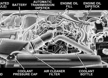
䡵 Engine Compartment – 3.8L . . . . . . . . . . . . . . . 378