- 2011 Jeep Wrangler Owners Manuals
- Jeep Wrangler Owners Manuals
- 2005 Jeep Wrangler Owners Manuals
- Jeep Wrangler Owners Manuals
- 2006 Jeep Wrangler Owners Manuals
- Jeep Wrangler Owners Manuals
- 2004 Jeep Wrangler Owners Manuals
- Jeep Wrangler Owners Manuals
- 2013 Jeep Wrangler Owners Manuals
- Jeep Wrangler Owners Manuals
- 2009 Jeep Wrangler Owners Manuals
- Jeep Wrangler Owners Manuals
- 2008 Jeep Wrangler Owners Manuals
- Jeep Wrangler Owners Manuals
- 2012 Jeep Wrangler Owners Manuals
- Jeep Wrangler Owners Manuals
- 2010 Jeep Wrangler Owners Manuals
- Jeep Wrangler Owners Manuals
- 2007 Jeep Wrangler Owners Manuals
- Jeep Wrangler Owners Manuals
- Download PDF Manual
-
WMA files). Discs created with an option such as ⬙keep disc open after writing⬙ are most likely multisession discs. The use of multisession for CD audio or MP3/ WMA playback may result in longer disc loading times. If a disc contains multi formats, such as CD audio and mp3/wma tracks, the radio will only play the mp3/wma tracks on that disc. Supported MP3/WMA File Formats The radio will recognize only files with the *.MP3/WMA extension as MP3/WMA files. Non-MP3/WMA files named with the *.MP3/WMA extension may cause play- back problems. The radio is designed to recognize the file as an invalid MP3/WMA and will not play the file. When using the MP3/WMA encoder to compress audio data to an MP3/WMA file, the bit rate and sampling
UNDERSTANDING YOUR INSTRUMENT PANEL 229
frequencies in the following table are supported. In addition, variable bit rates (VBR) are also supported. The majority of MP3/WMA files use a 44.1 kHz sampling rate and a 192, 160, 128, 96 or VBR bit rates.
MPEG
Specification
Sampling Fre- quency (kHz)
MPEG-1 Audio
Layer 3
48, 44.1, 32
MPEG-2 Audio
Layer 3
24, 22.05, 16
WMA
Specification
Sampling Fre- quency (kHz)
WMA
44.1 and 48
Bit rate (kbps)
320, 256, 224, 192, 160, 128, 112, 96, 80, 64,
56, 48
160, 128, 144, 112, 96, 80, 64,
56, 48
Bit Rate (kbps)
48, 64, 96, 128, 160, 192 VBR
230 UNDERSTANDING YOUR INSTRUMENT PANEL
ID3 Tag information for artist, song title, and album title are supported for version 1 ID3 tags. ID3 version 2 is not supported by the radios. Playlist files are not supported. MP3 Pro files are not supported. Playback of MP3/WMA Files When a medium containing MP3/WMA data is loaded, the radio checks all files on the medium. If the medium contains a lot of folders or files, the radio will take more time to start playing the MP3/WMA files. Loading times for playback of MP3/WMA files may be affected by the following: • Media - CD-RW media may take longer to load than • Medium formats - Multisession discs may take longer
CD-R media
to load than non-multisession discs
• Number of files and folders - Loading times will
increase with more files and folders
To increase the speed of disc loading, it is recommended to use CD-R media and single-session discs. To create a single-session disc, enable the Disc at Once option before writing to the disc. LIST Button (DISC Mode for MP3/WMA Play) Pressing the LIST button will bring up a list of all folders on the disc. Scrolling up or down the list is done by turning the TUNE control knob. Selecting a folder by pressing the TUNE control knob will begin playing the files contained in that folder (or the next folder in sequence if the selection does not contain playable files). The folder list will time out after 5 seconds.
INFO Button (DISC Mode for MP3/WMA Play) Pressing the INFO button repeatedly will scroll through the following TAG information: Song Title, Artist, File Name, and Folder Name (if available). Press the INFO button once more to return to ⬙elapsed time⬙ priority mode. Press and hold the INFO button for 3 seconds or more and radio will display song titles for each file. Press and hold the INFO button again for 3 seconds to return to ⬙elapsed time⬙ display. Operation Instructions - Auxiliary Mode The auxiliary (AUX) jack is an audio input jack, which allows the user to plug in a portable device such as an MP3/WMA player, cassette player, or microphone and utilize the vehicle’s audio system to amplify the source and play through the vehicle speakers.
UNDERSTANDING YOUR INSTRUMENT PANEL 231
Pushing the AUX button will change the mode to auxil- iary device if the AUX jack is connected. NOTE: The AUX device must be turned on and the device’s volume set to proper level. If the AUX audio is not loud enough, turn the device’s volume up. If the AUX audio sounds distorted, turn the device’s volume down. SEEK Button (Auxiliary Mode) No function. SCAN Button (Auxiliary Mode) No function. EJECT Button (Auxiliary Mode)
No function.
PSCAN Button (Auxiliary Mode) No function.
232 UNDERSTANDING YOUR INSTRUMENT PANEL
TIME Button (Auxiliary Mode) Press this button to change the display from elapsed playing time to time of day. The time of day will display for 5 seconds. RW/FF (Auxiliary Mode) No function. SET Button (Auxiliary Mode) No function. Operating Instructions - Hands Free Phone (UConnect™) (If Equipped) Refer to “Hands-Free Communication (UConnect™)” in Section 3 of this manual. Operating Instructions - Satellite Radio Mode (If Equipped) Refer to “Satellite Radio” in this section.
Operating Instructions - Video Entertainment System (VES威) (If Equipped) Refer to separate Video Entertainment System (VES威) Guide. Dolby Manufactured under license from Dolby Laboratories. ⬙Dolby⬙ and the double-D symbol are trademarks of Dolby Laboratories. Macrovision This product incorporates copyright protection technol- ogy that is protected by U.S. patents and other intellec- tual property rights. Use of this copyright protection technology must be authorized by Macrovision, and is intended for home and other limited viewing uses only unless otherwise authorized by Macrovision. Reverse engineering or disassembly is prohibited DTS ⬙DTS⬙ and ⬙DTS 2.0⬙ are trademarks of Digital Theater Systems, Inc.
SALES CODE RES — AM/FM STEREO RADIO WITH CD PLAYER (MP3 AUX JACK)
NOTE: The radio sales code is located on the lower right side of your radio faceplate.
RES Radio
UNDERSTANDING YOUR INSTRUMENT PANEL 233
Operating Instructions - Radio Mode
NOTE: The ignition switch must be in the ON or ACC position to operate the radio. Power Switch/Volume Control (Rotary) Press the ON/VOLUME control knob to turn on the radio. Press the ON/VOLUME control knob a second time to turn off the radio. Electronic Volume Control The electronic volume control turns continuously (360
degrees) in either direction without stopping. Turning the ON/VOLUME control knob to the right increases the volume and to the left decreases it. When the audio system is turned on, the sound will be set at the same volume level as last played. SEEK Buttons Press and release the SEEK buttons to search for the next listenable station in AM/FM mode. Press the right switch234 UNDERSTANDING YOUR INSTRUMENT PANEL
to seek up and the left switch to seek down. The radio will remain tuned to the new station until you make another selection. Holding either button will bypass stations without stopping until you release it. SCAN Button Pressing the SCAN button causes the tuner to search for the next listenable station in AM or FM frequencies, pausing for 5 seconds at each listenable station before continuing to the next. To stop the search, press the SCAN button a second time. Voice Recognition Button (UConnect™ Hands Free Phone) — If Equipped Press this button to operate the Hand Free Phone (UCon- nect™) feature (if equipped). Refer to Hands-Free Com- munication (UConnect™) in Section 3 for more informa- tion.
If your vehicle is not equipped with this feature, a “UConnect™ System Not Available” message will dis- play on the radio screen. Phone Button (UConnect™ Hands Free Phone) — If Equipped Press this button to operate the Hand Free Phone (UCon- nect™) feature (if equipped). Refer to Hands-Free Com- munication (UConnect™) in Section 3 for more informa- tion. If your vehicle is not equipped with this feature, a “UConnect™ System Not Available” message will dis- play on the radio screen. TIME Button Press the TIME button and the time of day will display. In AM or FM mode, pressing the TIME button will switch between the time and frequency displays.
Clock Setting Procedure 1. Press and hold the TIME button, until the hours blink. 2. Adjust the hours by turning the right side TUNE control knob. 3. After adjusting the hours, press the right side TUNE control knob to set the minutes. The minutes will begin to blink. 4. Adjust the minutes using the right side TUNE control knob. Press the TUNE control knob to save time change. 5. To exit, press any button/knob or wait 5 seconds. The clock can also be set by pressing the SETUP button, and selecting SET CLOCK. Once in this display follow the above procedure, starting at step 2.
UNDERSTANDING YOUR INSTRUMENT PANEL 235
INFO Button Press the INFO button for an RDS station (one with call letters displayed). The radio will return a Radio Text message broadcast from an FM station (FM mode only). RW/FF Pressing the RW (Rewind) or FF (Fast Forward) buttons causes the tuner to search for the next frequency in the direction of the arrows. This feature operates in either AM or FM frequencies. TUNE Control Turn the right side rotary control clockwise to increase or counter-clockwise to decrease the frequency. Setting the Tone, Balance, and Fade Press the rotary TUNE control knob and BASS will display. Turn the TUNE control knob to the right or left to increase or decrease the Bass tones.
236 UNDERSTANDING YOUR INSTRUMENT PANEL
Press the rotary TUNE control knob a second time and MID will display. Turn the TUNE control knob to the right or left to increase or decrease the Mid Range tones. Press the rotary TUNE control knob a third time and TREBLE will display. Turn the TUNE control knob to the right or left to increase or decrease the Treble tones. Press the rotary TUNE control knob a fourth time and BALANCE will display. Turn the TUNE control knob to the right or left to adjust the sound level from the right or left side speakers. Press the rotary TUNE control knob a fifth time and FADE will display. Turn the TUNE control knob to the left or right to adjust the sound level between the front and rear speakers. Press the rotary TUNE control knob again to exit setting tone, balance, and fade.
MUSIC TYPE Button Pressing this button once will turn on the Music Type mode for 5 seconds. Pressing the Music Type button or turning the TUNE control knob within 5 seconds will allow the program format type to be selected. Many radio stations do not currently broadcast Music Type information. Toggle the Music Type button to select the following format types:
Program Type
No program type
or undefined Adult Hits Classical
Classic Rock
College Country
Foreign Language
Information
16 Digit-Character
Display
None
Adlt Hit Classicl Cls Rock College Country Language
Inform
Jazz News
Nostalgia
Oldies
Personality
Public
Rhythm and Blues Religious Music Religious Talk
Rock Soft
Soft Rock
Soft Rhythm and Blues
Sports Talk Top 40
WeatherJazz News
Nostalga Oldies Persnlty Public R & B
Rel Musc Rel Talk
Rock Soft
Soft Rck Soft R&B
Sports Talk Top 40
WeatherUNDERSTANDING YOUR INSTRUMENT PANEL 237
By pressing the SEEK button when the Music Type icon is displayed, the radio will be tuned to the next frequency station with the same selected Music Type name. The Music Type function only operates when in the FM mode. If a preset button is activated while in the Music Type (Program Type) mode, the Music Type mode will be exited and the radio will tune to the preset station. SETUP Button Pressing the SETUP button allows you to select between the following items: • Set Clock — Pressing the SELECT button will allow user to set the clock. Turn the TUNE control knob to adjust the hours and then press and turn the TUNE control knob to adjust the minutes. Press the TUNE control knob again to save changes.
238 UNDERSTANDING YOUR INSTRUMENT PANEL
AM and FM Buttons Press the buttons to select AM or FM Modes. SET Button — To Set the Push-Button Memory When you are receiving a station that you wish to commit to push-button memory, press the SET button. The symbol SET 1 will now show in the display window. Select the button (1-6) you wish to lock onto this station and press and release that button. If a button is not selected within 5 seconds after pressing the SET button, the station will continue to play but will not be stored into push-button memory. You may add a second station to each push-button by repeating the above procedure with this exception: Press the SET button twice and SET 2 will show in the display window. Each button can be set for SET 1 and SET 2 in both AM and FM. This allows a total of 12 AM and 12 FM
stations to be stored into push-button memory. The stations stored in SET 2 memory can be selected by pressing the push-button twice. Every time a preset button is used, a corresponding button number will display. Buttons 1 - 6
These buttons tune the radio to the stations that you commit to push-button memory {12 AM and 12 FM stations}. DISC Button Pressing the DISC button will allow you to switch from AM/FM modes to Disc modes.Operation Instructions - CD MODE for CD and MP3 Audio Play
NOTE: The ignition switch must be in the ON or ACC position to operate the radio. NOTE: This Radio is capable of playing compact discs (CD), recordable compact discs (CD-R), rewritable com- pact discs (CD-RW) compact discs with MP3 tracks and multisession compact discs with CD and MP3 tracks. Inserting Compact Disc(s) Gently insert one CD into the CD player with the CD label facing up. The CD will automatically be pulled into the CD player and the CD icon will illuminate on the radio display. If a CD does not go into the slot more than an inch, a disc may already be loaded and must be ejected before a new disc can be loaded. If you insert a disc with the ignition ON and the radio ON, the unit will switch from radio to CD mode and
UNDERSTANDING YOUR INSTRUMENT PANEL 239
begin to play when you insert the disc. The display will show the disc number, the track number, and index time in minutes and seconds. Play will begin at the start of track 1.
CAUTION!
away and jam the player mechanism.
• This CD player will accept 4 3/4 inch (12 cm) discs only. The use of other sized discs may damage the CD player mechanism. • Do not use adhesive labels. These labels can peel • RES is a single CD player. Do not attempt to insert • Dual-media disc types (one side is a DVD, the other side is a CD) should not be used, and they can cause damage to the player.
a second CD if one is already loaded.
240 UNDERSTANDING YOUR INSTRUMENT PANEL
EJECT Button - Ejecting a CD
Press the EJECT button to eject the CD.
If you have ejected a disc and have not removed it within 10 seconds, it will be reloaded. If the CD is not removed, the radio will reinsert the CD but will not play it. A disc can be ejected with the radio and ignition OFF. NOTE: Ejecting with ignition OFF is not allowed on convertible or soft-top models (if equipped). SEEK Button Press the right SEEK button for the next selection on the CD. Press the left SEEK button to return to the beginning of the current selection, or return to the beginning of the previous selection if the CD is within the first second of
the current selection. Pressing and holding the SEEK button will allow to scroll through tracks faster in CD, MP3 modes. SCAN Button Press the Scan button to scan through each track on the CD currently playing. TIME Button Press this button to change the display from a large CD playing time display to a small CD playing time display. RW/FF Press the RW button to stop the CD at the beginning of the current CD track/title. Press and hold FF (Fast Forward) and the CD player will begin to fast forward until FF is released or RW or another CD button is pressed. The RW (Reverse) button works in a similar manner.
AM or FM Button Switches the Radio to the Radio mode. RND Button (Random Play Button) Press this button while the CD is playing to activate Random Play. This feature plays the selections on the compact disc in random order to provide an interesting change of pace. Press the right SEEK button to move to the next ran- domly selected track. Press the RND button a second time to stop Random Play. Notes On Playing MP3 Files The radio can play MP3 files; however, acceptable MP3
file recording media and formats are limited. When writing MP3 files, pay attention to the following restric- tions.UNDERSTANDING YOUR INSTRUMENT PANEL 241
Supported Media (Disc Types) The MP3 file recording media supported by the radio are CDDA, CD-R, CD-RW, MP3, and CDDA+MP3. Supported Medium Formats (File Systems) The medium formats supported by the radio are ISO 9660
Level 1 and Level 2 and includes the Joliet extension. When reading discs recorded using formats other than ISO 9660 Level 1 and Level 2, the radio may fail to read files properly and may be unable to play the file nor- mally. UDF and Apple HFS formats are not supported. The radio uses the following limits for file systems: • Maximum number of folder levels: 8
• Maximum number of files: 255
• Maximum number of folders (The radio display of file names and folder names is limited. For large numbers of files and/or folders, the radio may be unable to display the file name and folder name and will assign242 UNDERSTANDING YOUR INSTRUMENT PANEL
a number instead. With a maximum number of files, exceeding 20 folders will result in this display. With in this 200 files, exceeding 50 folders will result display. • Maximum number of characters in file/folder names: • Level 1: 12 (including a separator ⬙.⬙ and a • Level 2: 31 (including a separator
3-character extension)
⬙.⬙ and a
3-character extension)
Multisession disc formats are supported by the radio. Multisession discs may contain combinations of normal CD audio tracks and computer files (including MP3 files). Discs created with an option such as ⬙keep disc open after writing⬙ are most likely multisession discs. The use of multisession for CD audio or MP3 playback may result in longer disc loading times.
Supported MP3 File Formats The radio will recognize only files with the *.MP3 exten- sion as MP3 files. Non-MP3 files named with the *.MP3
extension may cause playback problems. The radio is designed to recognize the file as an invalid MP3 and will not play the file. When using the MP3 encoder to compress audio data to an MP3 file, the bit rate and sampling frequencies in the following table are supported. In addition, variable bit rates (VBR) are also supported. The majority of MP3 files use a 44.1 kHz sampling rate and a 192, 160, 128, 96 or VBR bit rates.MPEG
Specification
Sampling Fre- quency (kHz)
MPEG-1 Audio
Layer 3
48, 44.1, 32
MPEG-2 Audio
Layer 3
24, 22.05, 16
Bit Rate (kbps)
320, 256, 224, 192, 160, 128, 112, 96, 80, 64, 56, 48, 40, 32
160, 128, 144, 112, 96, 80, 64, 56, 48, 40, 32, 24,16, 8
ID3 Tag information for artist, song title, and album title are supported for version 1 ID3 tags. ID3 version 2 is not supported by the radios. Playlist files are not supported. MP3 Pro files are not supported.
UNDERSTANDING YOUR INSTRUMENT PANEL 243
Playback of MP3 Files When a medium containing MP3 data is loaded, the radio checks all files on the medium. If the medium contains a lot of folders or files, the radio will take more time to start playing the MP3 files. Loading times for playback of MP3 files may be affected by the following: • Media - CD-RW media may take longer to load than • Medium formats - Multisession discs may take longer • Number of files and folders - Loading times will
to load than non-multisession discs
CD-R media
increase with more files and folders
To increase the speed of disc loading, it is recommended to use CD-R media and single-session discs. To create a single-session disc, enable the Disc at Once option before writing to the disc.
244 UNDERSTANDING YOUR INSTRUMENT PANEL
LIST Button (CD Mode for MP3 Play) Pressing the LIST button will bring up a list of all folders on the disc. Scrolling up or down the list is done by turning the TUNE control knob. Selecting a folder by pressing the TUNE control knob will begin playing the files contained in that folder (or the next folder in sequence if the selection does not contain playable files). The folder list will time out after 5 seconds. INFO Button (CD Mode for MP3 Play) Pressing the INFO button repeatedly will scroll through the following TAG information: Song Title, Artist, File Name, and Folder Name (if available). Press the INFO button once more to return to ⬙elapsed time⬙ priority mode. Press and hold the INFO button for 3 seconds or more and radio will display song titles for each file.
Press and hold the INFO button again for 3 seconds to return to ⬙elapsed time⬙ display. Operation Instructions - Auxiliary Mode The auxiliary (AUX) jack is an audio input jack, which allows the user to plug in a portable device such as an MP3 player, or cassette player, and utilize the vehicle’s audio system to amplify the source and play through the vehicle speakers. Pushing the AUX button will change the mode to auxil- iary device if the AUX jack is connected. NOTE: The AUX device must be turned on and the device’s volume set to proper level. If the AUX audio is not loud enough, turn the device’s volume up. If the AUX audio sounds distorted, turn the device’s volume down.
TIME Button (Auxiliary Mode) Press this button to change the display to time of day. The time of day will display for 5 seconds (when ignition is off). Operating Instructions - Hands Free Phone (UConnect™) (If Equipped) Refer to “Hands-Free Communication (UConnect™)” in Section 3 of this manual. Operating Instructions - Satellite Radio Mode (If Equipped) Refer to “Satellite Radio” in this section. Operating Instructions - Video Entertainment System (VES威) (If Equipped) Refer to separate Video Entertainment System (VES威) Guide.
UNDERSTANDING YOUR INSTRUMENT PANEL 245
SALES CODE RER — AM/FM/CD/DVD RADIO WITH NAVIGATION SYSTEM — IF EQUIPPED
NOTE: The radio sales code is located on the lower right side of your radio faceplate. Satellite Navigation Radio with CD Player with MP3
Capability (RER) combines a Global-Positioning System-based navigation system with an integrated color screen to provide maps, turn identification, selection menus, and instructions for selecting a variety of desti- nations and routes. This radio has a hard drive. CD’s can be ripped to the hard drive, and the map data comes loaded on the hard drive. Refer to your “Navigation User’s Manual” for detailed operating instructions.246 UNDERSTANDING YOUR INSTRUMENT PANEL
Operating Instructions — Satellite Radio Refer to your “Navigation User’s Manual” for detailed operating instructions. Clock Setting Procedure The GPS receiver used in this system is synchronized to the time data being transmitted by the GPS satellite. The satellites’ clock is Greenwich Mean Time (GMT). This is the worldwide standard for time. This makes the sys- tem’s clock very accurate once the appropriate time zone and daylight savings information is set. To manually set the clock, change the time zone, or change daylight savings information, use a ballpoint pen or similar object to press the hour (H) or minute (M) buttons on the radio. The Setup screen appears. Setting the Clock 1. Turn the ignition switch to the ON or ACC position. Using the tip of a ballpoint pen or similar object, press
either the H button on the faceplate to change the hour or the M button on the faceplate to change the minute. 2. The time setting will increase each time you press the button. Holding either button in will fast forward the setting. 3. If no changes are made within 5 seconds of accessing the Setup screen, the screen will time out and you will be taken to the last mode. NOTE: To reset the clock, select the appropriate time zone and press ENTER. The clock will revert to the accurate time based on the time zone you selected. Changing the Time Zone 1. Highlight “Clock Setup” and press ENTER. 2. At the Clock Setup screen highlight the box next to “Time Zone” and press ENTER.
3. Highlight the appropriate time zone for you location and press ENTER to store your selection. Select “Done” when finished. NOTE: When you are traveling and enter a new time zone, the clock must be reset manually for the new zone. Changing Daylight Savings Time 1. Highlight the box next to “Time” and press ENTER. 2. Select Daylight Savings when Daylight Savings Time is in effect or Select Standard if Daylight Savings Time is not being observed. Press ENTER. 3. Select “Done” when finished. Select “Done” to exit from the clock setting mode.
UNDERSTANDING YOUR INSTRUMENT PANEL 247
SATELLITE RADIO — IF EQUIPPED Satellite radio uses direct satellite to receiver broadcast- ing technology to provide clear digital sound, coast to coast. The subscription service provider is Sirius™ Satel- lite Radio. This service offers up to 100 channels of music, sports, news, entertainment, and programming for chil- dren, directly from its satellites and broadcasting studios. System Activation Sirius Satellite Radio service is pre-activated, and you may begin listening immediately to the one year of SIRIUS audio service that is included with the factory- installed satellite radio system in your vehicle. Sirius will contact you to supply a welcome kit and to confirm subscription information, including the set up of your on-line listening account at no additional charge. For further information, call the toll-free number 888-539- 7474, or visit the Sirius web site at www.sirius.com. Please have the following information available when calling:
248 UNDERSTANDING YOUR INSTRUMENT PANEL
1. The Electronic Serial Number/Sirius Identification Number (ESN/SID). 2. Your Vehicle Identification Number. Electronic Serial Number/Sirius Identification Number (ENS/SID) The Electronic Serial Number/Sirius Identification Num- ber is needed to activate your Sirius Satellite Radio system. To access the ESN/SID, refer to the following steps: ESN/SID Access With RSC Radios With the ignition switch in the ON/RUN or ACCESSORY position and the radio ON, press the SETUP button and scroll using the TUNE control knob until Sirius ID is selected. Press the TUNE control knob and the Sirius ID number will display. The Sirius ID number display will time out in 2 minutes. Press any button on the radio to exit this screen.
Selecting Satellite Mode (RSC Radios) Press the SAT button until ⬙SAT⬙ appears in the display. A CD may remain in the radio while in the Satellite radio mode. Satellite Antenna To ensure optimum reception, do not place items on the roof around the rooftop antenna location or strap items to the trunk lid around the trunk lid antenna (if equipped). Metal objects placed within the line of sight of the antenna will cause decreased performance. Larger lug- gage items such as bikes should be placed as far rearward as possible, within the loading design of the rack. Do not place items directly on or above the antenna. Reception Quality Satellite reception may be interrupted due to one of the following reasons: • The vehicle is parked in an underground parking
structure or under a physical obstacle.
form of short audio mutes.
• Dense tree coverage may interrupt reception in the • Driving under wide bridges or along tall buildings can • Placing objects over or too close to the antenna can
cause intermittent reception.
cause signal blockage.
Operating Instructions - Satellite Mode
NOTE: The ignition switch must be in the ON or ACC position to operate the radio. SEEK Buttons Press and release the SEEK buttons to search for the next channel in Satellite mode. Press the right switch to seek up and the left switch to seek down. The radio will remain tuned to the new channel until you make another selection. Holding either button will bypass channels without stopping until you release it.
UNDERSTANDING YOUR INSTRUMENT PANEL 249
SCAN Button Pressing the SCAN button causes the tuner to search for the next channel, pausing for 8 seconds before continuing to the next. To stop the search, press the SCAN button a second time. INFO Button Pressing the INFO button will cycle between Artist, Song Title, and Composer (if available) information. Also, pressing and holding the INFO button for an additional 3 seconds will make the radio display the Song Title all of the time (press and hold again to return to normal display). RW/FF Pressing the RW (Rewind) or FF (Fast Forward) buttons causes the tuner to search for the next channel in the direction of the arrows.
250 UNDERSTANDING YOUR INSTRUMENT PANEL
TUNE Control (Rotary) Turn the right side rotary control clockwise to increase or counter-clockwise to decrease the channel. MUSIC TYPE Button Pressing this button once will turn on the Music Type mode for 5 seconds. Pressing the MUSIC TYPE button or turning the TUNE control knob within 5 seconds will allow the program format type to be selected. Toggle the MUSIC TYPE button again to select the music type. By pressing the SEEK button when the Music Type function is active, the radio will be tuned to the next channel with the same selected Music Type name. If a preset button is activated while in the Music Type (Program Type) mode, the Music Type mode will be exited and the radio will tune to the preset channel.
SETUP Button Pressing the SETUP button allows you to select the following items: • Display Sirius ID number — Press the SELECT button to display the Sirius ID number. This number is used to activate, deactivate, or change the Sirius subscrip- tion.
SET Button — To Set the Push-Button Memory When you are receiving a channel that you wish to commit to push-button memory, press the SET button. The symbol SET 1 will now show in the display window. Select the button (1-6) you wish to lock onto this channel and press and release that button. If a button is not selected within 5 seconds after pressing the SET button, the channel will continue to play but will not be stored into push-button memory. You may add a second channel to each push-button by repeating the above procedure with this exception: Press
the SET button twice and SET 2 will show in the display window. Each button can be set for SET 1 and SET 2. This allows a total of 12 Satellite channels to be stored into push-button memory. The channels stored in SET 2
memory can be selected by pressing the push-button twice. Every time a preset button is used, a corresponding button number will display. Buttons 1 - 6
These buttons tune the radio to the channels that you commit to push-button memory {12 Satellite stations}. Operating Instructions - Hands Free Phone (If Equipped) Refer to Hands Free Phone in Section 3 of the Owner’s Manual.UNDERSTANDING YOUR INSTRUMENT PANEL 251
Operating Instructions - Video Entertainment System (VES姞) (If Equipped) Refer to separate Video Entertainment System (VES威) Guide.
CD/DVD DISC MAINTENANCE To keep the CD/DVD discs in good condition, take the following precautions: 1. Handle the disc by its edge; avoid touching the surface. 2. If the disc is stained, clean the surface with a soft cloth, wiping from center to edge. 3. Do not apply paper, paper CD labels, or tape to the disc; avoid scratching the disc. 4. Do not use solvents such as benzine, thinner, cleaners, or antistatic sprays. 5. Store the disc in its case after playing.
252 UNDERSTANDING YOUR INSTRUMENT PANEL
6. Do not expose the disc to direct sunlight. 7. Do not store the disc where temperatures may become too high.
RADIO OPERATION AND CELLULAR PHONES Under certain conditions, the cellular phone being ON in your vehicle can cause erratic or noisy performance from your radio. This condition may be lessened or eliminated by relocating the cellular phone antenna. This condition is not harmful to the radio. If your radio performance does not satisfactorily “clear” by the repositioning of the antenna, it is recommended that the radio volume be turned down or off during cellular phone operation.
CLIMATE CONTROLS
Manual Heater Only The controls for the heating/ventilation system in this vehicle consist of a series of rotary knobs. These comfort controls can be set to obtain desired interior conditions.
Manual Heater Control
Mode Control The mode control (left rotary knob) allows you to choose from several patterns of air distribution. You can select either a primary mode, as identified by the symbols, or a blend of two of these modes. The closer the control is to a particular mode, the more air distribution you receive from that mode. Panel
Air is directed through the outlets in the instrument panel. These outlets can be adjusted to direct air
flow. Bi-Level
Air is directed through the panel and floor outlets.
NOTE: There is a difference in temperature between the upper and lower outlets for added comfort. The warmer air goes to the floor outlets. This feature gives improved comfort during sunny but cool conditions.
UNDERSTANDING YOUR INSTRUMENT PANEL 253
Floor
Air is directed through the floor outlets and side window demist outlets with a small amount
through the defrost outlet. Mix
Air is directed through the floor, defrost and side window demist outlets. This setting works best in cold or snowy conditions that require extra heat at the windshield. This setting is good for maintaining comfort while reducing moisture on the windshield. Defrost
Air is directed through the windshield and side window demist outlets. Use this mode with maxi- mum fan and temperature settings for best windshield and side window defrosting. Blower Control Use this control (center rotary knob) to regulate the amount of air forced through the system in any mode
254 UNDERSTANDING YOUR INSTRUMENT PANEL
you select. The fan speed increases as you move the control to the right from the OFF position. Temperature Control Use this control (right rotary knob) to regulate the temperature of the air inside the passenger compartment. The blue area of the scale indicates cooler temperatures while the red area indicates warmer temperatures. Manual Air Conditioning and Heating System — If Equipped The controls for the heating/air conditioning and venti- lation system in this vehicle consist of a series of rotary knobs. These comfort controls can be set to obtain desired interior conditions.
The instrument panel features four airflow registers. Two registers are located on the outer ends of the instrument panel and two are located in the center of the instrument panel. These registers can be closed to partially block airflow, and they can be adjusted to direct airflow where the occupant desires.
Mode Control
The mode control allows you to choose from several pat- terns of air distribution. You can select either a primary mode, as identified by the symbols, or a blend of two of these modes. The closer the control to a particular mode, the more air distribu- tion you receive from that mode.
is
Panel
flow.
Air is directed through the outlets in the instrument panel. These outlets can be adjusted to direct air
UNDERSTANDING YOUR INSTRUMENT PANEL 255
Bi-Level
Air is directed through the panel and floor outlets.
NOTE: There is a difference in temperature between the upper and lower outlets for added comfort. The warmer air goes to the floor outlets. This feature gives improved comfort during sunny but cool conditions. Floor
Air is directed through the floor outlets and side window demist outlets with a small amount
through the defrost outlet. Mix
Air is directed through the floor, defrost and side window demist outlets. This setting works best in cold or snowy conditions that require extra heat at the windshield. This setting is good for maintaining comfort while reducing moisture on the windshield.
256 UNDERSTANDING YOUR INSTRUMENT PANEL
Defrost
Air is directed through the windshield and side window demist outlets. Use this mode with maxi- mum fan and temperature settings for best windshield and side window defrosting. NOTE: The air conditioning compressor operates in both Mix and Defrost or a blend of these modes even if the fan switch is not in the A/C position. This dehumidi- fies the air to help dry the windshield. To improve fuel economy, use these modes only when necessary.
Blower Control
Use this control to regulate the amount of air forced through the system in any mode you select. The fan speed increases as you move the control to the right from the OFF position.
UNDERSTANDING YOUR INSTRUMENT PANEL 257
Temperature Control
Circulation Control
Use this control to regulate the temperature of the air in- side the passenger compart- ment. The blue area of the scale indicates cooler tem- peratures while the red area indicates warmer tempera- tures.
Press this button to choose between outside air intake or recirculation of the air inside the vehicle. A lamp will illu- minate when you are in “Re- circulate” mode. Only use the “Recirculate” mode to tempo- rarily block out any outside odors, smoke, or dust and to cool the interior rapidly upon
If your air conditioning performance seems NOTE: lower than expected, check the front of the A/C con- denser: located in front of the radiator, for an accumula- tion of dirt or insects. Clean with a gentle water spray from behind the radiator and through the condenser. Fabric front fascia protectors may reduce air flow to the condenser, reducing air conditioning performance.
initial start up in very hot or humid weather. NOTE: Continuous use of the “Recirculate” mode may make the inside air stuffy and window fogging may occur. Extended use of this mode is not recommended. In cold or damp weather, the use of the “Recirculate” mode will cause windows to fog on the inside because of
258 UNDERSTANDING YOUR INSTRUMENT PANEL
moisture build up inside the vehicle. For maximum defogging, select the Outside Air position. NOTE: The “Recirculate” mode will not operate in floor, mix or defrost modes. Air Conditioning Operation
Press this button to engage the air conditioning. A lamp will illuminate when the air conditioning system is en- gaged
NOTE: The air conditioning compressor will not engage until the engine has been running for about 10 seconds.
Operating Tips
Window Fogging Windows will fog on the inside when the humidity inside the vehicle is high. This often occurs in mild or cool temperatures when it’s rainy or humid. In most cases turning on the air-conditioning (pressing the snowflake button) will clear the fog. Adjust the temperature control, air direction and blower speed to maintain comfort. As the temperature gets colder it may be necessary to direct air onto the windshield. Adjust the temperature control and blower speed to maintain comfort. Higher blower speeds will reduce fogging. Interior fogging on the windshield can be quickly removed by selecting the defrost mode. Regular cleaning of the inside of the windows with a non-filming cleaning solution (vinegar and water works very well) will help prevent contaminates (cigarette
smoke, perfumes, etc.) from sticking to the windows. Contaminates increase the rate of window fogging. Summer Operation Air conditioned vehicles must be protected with a high quality antifreeze coolant during summer to provide proper corrosion protection and to raise the boiling point of the coolant for protection against overheating. A 50 % concentration is recommended. Refer to Fluids and Genuine Parts in Section 7 for the proper coolant type. When using the air conditioner in extremely heavy traffic in hot weather especially when towing a trailer, addi- tional engine cooling may be required. If this situation is encountered, operate the transmission in a lower gear to increase engine RPM, coolant flow and fan speed. When stopped in heavy traffic, it may be necessary to shift into N (Neutral) and depress the accelerator slightly for fast idle operation to increase coolant flow and fan speed.
UNDERSTANDING YOUR INSTRUMENT PANEL 259
Winter Operation When operating the system during the winter months, make sure the air intake, located directly in front of the windshield, is free of ice, slush, snow, or other obstruc- tions. Vacation Storage Anytime you store your vehicle, or keep it out of service (i.e. vacation) for two weeks or more, run the air condi- tioning system at idle for about five minutes in the fresh air and high blower setting. This will insure adequate system lubrication to minimize the possibility of com- pressor damage when the system is started again.
STARTING AND OPERATING
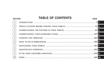
CONTENTS
䡵 Starting Procedures . . . . . . . . . . . . . . . . . . . . . 265
▫ Manual Transmission . . . . . . . . . . . . . . . . . . 265
▫ Automatic Transmission . . . . . . . . . . . . . . . . 265
▫ Normal Starting . . . . . . . . . . . . . . . . . . . . . . 265
▫ Extreme Cold Weather(Below –20°F Or –29°C) . . . . . . . . . . . . . . . . . 266
▫ If Engine Fails To Start . . . . . . . . . . . . . . . . . 266
▫ After Starting . . . . . . . . . . . . . . . . . . . . . . . . 268
䡵 Engine Block Heater — If Equipped . . . . . . . . . 269䡵 Manual Transmission . . . . . . . . . . . . . . . . . . . . 269
▫ 6-Speed Manual Transmission . . . . . . . . . . . . 269
䡵 Automatic Transmission . . . . . . . . . . . . . . . . . . 273
▫ Shift Lock Manual Override . . . . . . . . . . . . . . 274
▫ Brake/Transmission Interlock System . . . . . . . 275
▫ Automatic Transmission With Overdrive . . . . . 275䡵 Four–Wheel Drive Operation (Command-Trac™
Or Rock-Trac™) — If Equipped . . . . . . . . . . . . . 280
▫ Operating Instructions/Precautions . . . . . . . . . 280262 STARTING AND OPERATING
▫ Shift Positions . . . . . . . . . . . . . . . . . . . . . . . . 282
▫ Shifting Procedure . . . . . . . . . . . . . . . . . . . . 283
䡵 Trac-Lok™ Rear Axle — If Equipped . . . . . . . . . 284
䡵 Axle Lock (Tru–Lok™) — Rubicon Models . . . . . 285
䡵 Rear Axle Lock — 4WD Non-Rubicon Models(If Equipped) . . . . . . . . . . . . . . . . . . . . . . . . . . 286
䡵 Electronic Sway Bar Disconnect — If Equipped . . 287
䡵 On-Road Driving Tips . . . . . . . . . . . . . . . . . . . 289
䡵 Off-Road Driving Tips . . . . . . . . . . . . . . . . . . . 290
▫ When To Use 4L (Low) Range . . . . . . . . . . . . 290
▫ Driving Through Water . . . . . . . . . . . . . . . . . 291
▫ Driving In Snow, Mud And Sand . . . . . . . . . . 292
▫ Hill Climbing . . . . . . . . . . . . . . . . . . . . . . . . 292▫ Traction Downhill . . . . . . . . . . . . . . . . . . . . . 293
▫ After Driving Off-Road . . . . . . . . . . . . . . . . . 294
䡵 Parking Brake . . . . . . . . . . . . . . . . . . . . . . . . . 295
䡵 Anti-Lock Brake System . . . . . . . . . . . . . . . . . . 296
䡵 Power Steering . . . . . . . . . . . . . . . . . . . . . . . . 298
䡵 Tire Safety Information . . . . . . . . . . . . . . . . . . . 300
▫ Tire Markings . . . . . . . . . . . . . . . . . . . . . . . . 300
▫ Tire Identification Number (TIN) . . . . . . . . . . 303
▫ Tire Loading And Tire Pressure . . . . . . . . . . . 304
䡵 Tires — General Information . . . . . . . . . . . . . . . 308
▫ Tire Pressure . . . . . . . . . . . . . . . . . . . . . . . . . 308
▫ Tire Inflation Pressures . . . . . . . . . . . . . . . . . 309
▫ Tire Pressures For High Speed Operation . . . . 311▫ Radial-Ply Tires . . . . . . . . . . . . . . . . . . . . . . 312
▫ Tire Spinning . . . . . . . . . . . . . . . . . . . . . . . . 312
▫ Tread Wear Indicators . . . . . . . . . . . . . . . . . . 312
▫ Life Of Tire . . . . . . . . . . . . . . . . . . . . . . . . . 313
▫ Replacement Tires . . . . . . . . . . . . . . . . . . . . . 314
▫ Alignment And Balance . . . . . . . . . . . . . . . . . 315
䡵 Tire Chains . . . . . . . . . . . . . . . . . . . . . . . . . . . 315
䡵 Tire Rotation Recommendations . . . . . . . . . . . . 316
䡵 Tire Pressure Monitor System (TPMS) — IfEquipped . . . . . . . . . . . . . . . . . . . . . . . . . . . . 317
▫ Base System — If Equipped . . . . . . . . . . . . . . 318
▫ General Information . . . . . . . . . . . . . . . . . . . 321
䡵 Fuel Requirements . . . . . . . . . . . . . . . . . . . . . . 321STARTING AND OPERATING 263
▫ Reformulated Gasoline . . . . . . . . . . . . . . . . . 322
▫ Gasoline/Oxygenate Blends . . . . . . . . . . . . . . 322
▫ MMT In Gasoline . . . . . . . . . . . . . . . . . . . . . 323
▫ Materials Added To Fuel . . . . . . . . . . . . . . . . 323
▫ Fuel System Cautions . . . . . . . . . . . . . . . . . . 324
▫ Carbon Monoxide Warnings . . . . . . . . . . . . . . 324
. . . . . . . . . . . . . . . . . . . . . . . . . . 325
. . . . . . . . . . . . . . . 325
䡵 Vehicle Loading . . . . . . . . . . . . . . . . . . . . . . . . 328
▫ Certification Label . . . . . . . . . . . . . . . . . . . . . 328
䡵 Trailer Towing . . . . . . . . . . . . . . . . . . . . . . . . . 330
▫ Common Towing Definitions . . . . . . . . . . . . . 330
▫ Trailer Hitch Classification . . . . . . . . . . . . . . . 334▫ Fuel Filler Cap (Gas Cap)
䡵 Adding Fuel
264 STARTING AND OPERATING
▫ Trailer Towing Weights (Maximum Trailer
Weight Ratings)
. . . . . . . . . . . . . . . . . . . . . . 335
▫ Trailer And Tongue Weight . . . . . . . . . . . . . . 338
▫ Towing Requirements . . . . . . . . . . . . . . . . . . 339
▫ Towing Tips . . . . . . . . . . . . . . . . . . . . . . . . . 344䡵 Recreational Towing (Behind Motorhome, Etc.) . . 346
▫ Towing – 2WD Models . . . . . . . . . . . . . . . . . 346
▫ Towing – 4WD Models . . . . . . . . . . . . . . . . . 346
▫ Shifting Out Of Neutral (N) . . . . . . . . . . . . . . 347STARTING PROCEDURES Before starting your vehicle, adjust your seat, adjust both inside and outside mirrors, and fasten your seat belts.
WARNING!
Never leave children alone in a vehicle. Leaving children in a vehicle unattended is dangerous for a number of reasons. A child or others could be seri- ously or fatally injured. Do not leave the keys in the ignition. A child could operate power windows, other controls, or move the vehicle.
Manual Transmission Apply the parking brake, place the gearshift control lever in N (Neutral) and depress the clutch pedal before starting vehicle. This vehicle is equipped with a clutch interlocking ignition system. It will not start unless the clutch pedal is pressed to the floor.
STARTING AND OPERATING 265
4WD Models Only In 4L mode, this vehicle will start regardless of whether or not the clutch pedal is pressed to the floor. This feature enhances off-road performance by allowing the vehicle to start when in 4L without having to depress the clutch pedal. The “4WD Indicator Light” will illuminate when the transfer case has been shifted into this mode. Automatic Transmission Start the engine with the selector lever in the N (Neutral) or P (Park) position. Apply the brake before shifting to any driving range. Normal Starting Normal starting of either a cold or a warm engine is obtained without pumping or depressing the accelerator pedal. Turn the key to the START position and release when the engine starts. If the engine fails to start within 10 seconds, turn the key to the OFF position, wait 5
seconds, then repeat the normal starting procedure.266 STARTING AND OPERATING
Tip Start Feature — Automatic Transmission Only Do not press the accelerator. Turn the ignition key briefly to START position, and release it. The starter motor will continue to run, but will automatically disengage itself when the engine is running.
Extreme Cold Weather (below –20°F or –29°C) To insure reliable starting at these temperatures, use of an externally powered electric engine block heater (available from your dealer) is recommended. If Engine Fails to Start If the engine fails to start after you have followed the “Normal Starting” or “Extreme Cold Weather” proce- dures, it may be flooded. Push the accelerator pedal all the way to the floor and hold it there while cranking the engine. This should clear any excess fuel in case the engine is flooded.
Ignition Key Positions
STARTING AND OPERATING 267
CAUTION!
WARNING!
To prevent damage to the starter, do not crank the engine for more than 15 seconds at a time. Wait 10 to 15 seconds before trying again.
WARNING!
Never pour fuel or other flammable liquids into the throttle body air inlet opening in an attempt to start the vehicle. This could result in a flash fire causing serious personal injury.
Do not attempt to push or tow your vehicle to get it started. Vehicles equipped with an automatic trans- mission cannot be started this way. Unburned fuel could enter the catalytic converter and once the engine has started, ignite and damage the converter and vehicle. If the vehicle has a discharged battery, booster cables may be used to obtain a start from a booster battery or the battery in another vehicle. This type of start can be dangerous if done improperly. Refer to Section 6 of this manual for proper jump starting procedures and follow them carefully.
268 STARTING AND OPERATING
If the engine has been flooded, it may start to run, but not have enough power to continue running when the key is released. If this occurs, continue cranking with the accel- erator pedal pushed all the way to the floor. Release the accelerator pedal and the key once the engine is running smoothly. If the engine shows no sign of starting after two 15
second periods of cranking with the accelerator pedal held to the floor, the “Normal Starting” or “Extreme Cold Weather” procedures should be repeated. After Starting The idle speed will automatically decrease as the engine warms up.WARNING!
Never leave children alone in a vehicle. Leaving children in a vehicle unattended is dangerous for a number of reasons. A child or others could be seri- ously or fatally injured. Do not leave the keys in the ignition. A child could operate power windows, other controls, or move the vehicle.
STARTING AND OPERATING 269
MANUAL TRANSMISSION
6-Speed Manual Transmission
WARNING!
You or others could be injured if you leave the vehicle unattended without having the parking brake fully applied. The parking brake should al- ways be applied when the driver is not in the vehicle, especially on an incline.
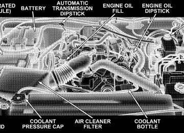
ENGINE BLOCK HEATER — IF EQUIPPED The engine block heater warms engine coolant and permits quicker starts in cold weather. Connect the cord to a standard 110-115 volt AC electrical outlet with a grounded, three wire extension cord. The engine block heater cord is found under the hood bundled in front of the battery tray.
WARNING!
Remember to disconnect the cord before driving. Damage to the 110-115 volt AC electrical cord could cause electrocution.
Use the heater when temperatures below 0°F (-18°C) are expected to last for several days.
270 STARTING AND OPERATING
Follow the shift pattern on the gearshift knob. NOTE: The backup lights will come on when your vehicle is in R (Reverse) gear and the ignition is in the ON position.
Manual Shift Controls
WARNING!
When parking your vehicle, always leave a manual transmission in first gear and apply the parking brake fully to guard against vehicle movement and possible injury or damage. Never use any gear as a substitute for the parking brake.
CAUTION!
To drive as safely as possible and to prolong the life of your manual transmission, follow these tips:
• Before shifting from a forward gear into reverse, or from reverse to a forward gear, stop vehicle com- pletely. Otherwise, transmission damage may result.
heat buildup and damages the clutch.
speeds in lower gears. Engine damage may result.
• Do not operate at sustained high engine or road • Do not downshift into a low gear while traveling at too high a speed for that gear. Engine, clutch, or transmis- sion damage may result. • Do not rest your foot on the clutch pedal. This causes • When you slow down or go up a grade, downshift as • Never hold the vehicle stopped on a hill by using the • During cold weather, you may experience increased effort in shifting until the transmission fluid warms up. This is normal. • Push in the clutch pedal completely when shifting. Otherwise, transmission or clutch damage may result.
speed requires or the engine may overheat.
clutch pedal. The clutch may be damaged.
STARTING AND OPERATING 271
• When “rocking” a stuck vehicle by shifting between a forward gear and reverse, do not spin wheels faster than 15 mph (24 km/h), or drivetrain damage may result.
Recommended Manual Transmission Shifting Speeds The manufacturer recommends that you use the shift speeds listed in the chart below. Manual Transmission Shift Speeds in MPH (KM/H) En- gine 3.8L
2 to 3 3 to 4 4 to 5 5 to 6
Speeds
15 (24)
Accel.
1 to 2
Cruise
10 (16)
24
(39) 19
(31)34
(55) 27
(43)47
(76) 37
(60)56
(90) 41
(66)272 STARTING AND OPERATING
Recommended Manual Transmission Downshifting Speeds To prevent clutch and transmission damage, your vehicle should be downshifted at speeds no greater than those listed in the chart below:
Manual Transmission Downshift Speeds in MPH
(KM/H)
6th to 5th
5th to 4th
4th to 3rd
3rd to 2nd
2nd to
1st
88 (142) 71 (114)
51 (82)
33 (53)
20 (32)
Gear Selec- tion Maxi- mum Speed
CAUTION!
Failure to follow the recommended downshifting speeds may cause the engine to over speed and/or damage the clutch disc even if the clutch pedal is depressed.
STARTING AND OPERATING 273
WARNING!
It is dangerous to shift the selector lever out of P (Park) or N (Neutral) if the engine speed is higher than idle speed. If your foot is not firmly on the brake pedal, the vehicle could accelerate quickly forward or in reverse. You could lose control of the vehicle and hit someone or something. Only shift into gear when the engine is idling normally and when your foot is firmly on the brake pedal.
AUTOMATIC TRANSMISSION
CAUTION!
to a complete stop.
Damage to the transmission may occur if the follow- ing precautions are not observed: • Shift into P (Park) only after the vehicle has come • Shift into or out of R (Reverse) only after the vehicle has come to a complete stop and the engine is at idle speed. • Do not shift from R (Reverse), P (Park), or N (Neutral) into any forward gear when the engine is above idle speed. • Before shifting into any gear, make sure your foot
is firmly on the brake pedal.
274 STARTING AND OPERATING
Shift Lock Manual Override Your vehicle may be equipped with a shift lock manual override. The manual override may be used in the event that the shift lever should fail to move from Park with the key in the ON position and the brake pedal depressed. To operate the shift lock manual override, perform the following steps: 1. Firmly set the parking brake. 2. Using a flat blade screwdriver, carefully remove the shift lock manual override cover which is located on the PRNDL bezel, in front of the P (Park) graphic. 3. Depress and maintain firm pressure on the service brake pedal. 4. Using the screwdriver, reach into the manual override opening. Press and hold the shift lock lever down.
5. Depress the shifter release button and shift into N (Neutral). 6. The vehicle may then be started in N (Neutral). Have your vehicle inspected by your local authorized dealer, if the shift lock manual override has been used.
Brake/Transmission Interlock System This system prevents you from moving the gear shift out of P (Park) and into any gear unless the brake pedal is pressed. This system is active only while the ignition switch is in the ON position. Always depress the brake pedal first, before moving the gear selector out of P (Park). Automatic Transmission with Overdrive Shifting from D (Drive) to P (Park) or R (Reverse) (or from P or R to D) should be done only after the accelerator pedal is released and the vehicle is stopped. Be sure to keep your foot on the brake when moving the shift lever between these gears.
STARTING AND OPERATING 275
Automatic Shift Controls
276 STARTING AND OPERATING
Gear Ranges DO NOT race the engine when shifting from P (Park) or N (Neutral) position into another gear range. P (Park) This gear position supplements the parking brake by locking the transmission. The engine can be started in this range. Never use P (Park) while the vehicle is in motion. Apply the parking brake when leaving the vehicle in this range. Always apply parking brake first, then place the selector in P (Park) position.
WARNING!
Never use P (Park) position as a substitute for the parking brake. Always apply parking brake fully when parked to guard against vehicle movement and possible injury or damage.
WARNING!
It is dangerous to shift the selector lever out of P (Park) or N (Neutral) if the engine speed is higher than idle speed. If your foot is not firmly on the brake pedal, the vehicle could accelerate quickly forward or in reverse. You could lose control of the vehicle and hit someone or something. Only shift into gear when the engine is idling normally and when your right foot is firmly on the brake pedal.
R (Reverse) Use this range only after the vehicle has come to a complete stop. N (Neutral) Shift into N (Neutral) when the vehicle is standing for prolonged periods with the engine running. The engine may be started in this range. Set the parking brake if you must leave the vehicle. NOTE: Towing the vehicle, coasting, or driving for any other reason with selector lever in N (Neutral) can result in severe transmission damage. Refer to “Recreational Towing” in Section 5 and “Towing a Disabled Vehicle” in Section 6 of this manual.
STARTING AND OPERATING 277
Overdrive (O/D) For most city and highway driving. The transmission contains an electronically controlled Overdrive, and will automatically shift from D (Drive) to O/D (Overdrive) if the following conditions are present: • The transmission selector is in D (Drive). • The O/D OFF switch has not been activated. • Vehicle speed is above approximately 30 mph (48
km/h).
278 STARTING AND OPERATING
When frequent transmission shifting occurs while using Overdrive, such as when operating the vehicle under heavy load conditions (for example, in hilly terrain, strong head winds, or trailer towing), turning off over- drive will improve performance and extend transmission life by reducing excessive shifting and heat buildup.
Overdrive Off Switch
Overdrive can be locked out by pressing the O/D OFF switch located on the center console. The O/D OFF indicator light (on the switch) will illuminate to show that the switch has been activated. When the indicator light is on, Overdrive is locked out. Pressing the switch a second time restores the Overdrive function. The lockout feature is useful when towing a trailer or carrying a heavy load. 2 (Second) For moderate grades and to assist braking on dry pave- ment or in mud and snow. Begins at a stop in low gear with automatic upshift to 2nd gear. Will not shift to 3rd. 1 (First) For hard pulling at low speeds in mud, sand, snow, or on steep grades. Begins and stays in low gear with no upshift. Provides engine compression braking at low speeds.
WARNING!
Never use P (Park) position with an automatic trans- mission as a substitute for the parking brake. Always apply parking brake fully when parked to guard against vehicle movement and possible injury or damage.
STARTING AND OPERATING 279
CAUTION!
• Before moving the shift lever out of P (Park), you must turn the ignition from LOCK so the steering wheel and shift lever are released. Otherwise, damage to steering column or shifter could result. • Never race the engine with the brakes on and the vehicle in gear, and never hold the vehicle on an incline without applying the brakes. These prac- tices can overheat and damage the transmission. • When “rocking” a stuck vehicle by moving be- tween D (Drive) and R (Reverse), do not spin the wheels faster than 15 mph (24 km/h), or drivetrain damage may result.
280 STARTING AND OPERATING
Torque Converter Clutch A feature designed to improve fuel economy has been added to the automatic transmission of this vehicle. A clutch within the torque converter engages automatically at calibrated speeds. This may result in a slightly differ- ent feeling or response during normal operation in high gear. When the vehicle speed drops or during accelera- tion, the clutch automatically and smoothly disengages.
FOUR–WHEEL DRIVE OPERATION (COMMAND-TRAC™ OR ROCK-TRAC™) — IF EQUIPPED
Operating Instructions/Precautions The transfer case provides four mode positions — two (rear) wheel drive high range, four wheel drive high range, neutral, and four wheel drive low range.
4WD Shift Controls
This transfer case is intended to be driven in the two wheel drive (2H) position for normal street and highway conditions such as hard surfaced roads. In the events when additional traction is required, the transfer case 4H and 4L positions can be used to lock the front and rear driveshafts together and force the front and rear wheels to rotate at the same speed. This is accomplished by simply moving the shift lever to these positions. The 4H and 4L positions are intended for loose, slippery road surfaces only and not intended for normal driving. Driving in the 4H and 4L positions on hard surfaced roads will cause increased tire wear and damage to the driveline components. The “4WD Indicator Light” (located in the instrument cluster) alerts the driver that the vehicle is in four wheel drive and that the front and rear driveshafts are locked together. This light illuminates when the transfer case is shifted into the 4H position.
STARTING AND OPERATING 281
NOTE: Do not attempt to make a shift while only the front or rear wheels are spinning. The transfer case is not equipped with a synchronizer and therefore the front and rear driveshafts speeds must be equal for the shift to take place. Shifting while only the front or rear wheels are spinning can cause damage to the transfer case. When operating your vehicle in 4L, the engine speed is approximately three times (four times for Rubicon mod- els) that of the 2H or 4H positions at a given road speed. Take care not to overspeed the engine. Proper operation of four wheel drive vehicles depends on tires of equal size, type, and circumference on each wheel. Any difference will adversely affect shifting and cause damage to the transfer case. Because four wheel drive provides improved traction, there is a tendency to exceed safe turning and stopping speeds. Do not go faster than road conditions permit.
282 STARTING AND OPERATING
WARNING!
You or others could be injured if you leave the vehicle unattended with the transfer case in the N (Neutral) position without first fully engaging the parking brake. The transfer case N (Neutral) position disengages both the front and rear driveshafts from the powertrain and will allow the vehicle to move regardless of the transmission position. The parking brake should always be applied when the driver is not in the vehicle.
Shift Positions
For additional information on the appropriate use of each transfer case mode position, see the information below:
2H Position Rear Wheel Drive High Range — Normal street and highway driving. Hard surfaced roads. 4H Position Four Wheel Drive High Range — Locks the front and rear driveshafts together. Forces the front and rear wheels to rotate at the same speed. This range (4H) provides additional traction for loose, slippery road surfaces and should not be used on wet or dry pavement.
WARNING!
Do not drive this vehicle in excess of 50 mph (80
km/h) with the transfer case in the four wheel drive high range (4H). Failure to follow this warning can result in loss of control and an accident causing serious and fatal injuries.The “4WD Indicator Light” (located in the instrument cluster) will illuminate when the transfer case is shifted into the 4H position. N (Neutral) Position Neutral — Disengages both the front and rear driveshafts from the powertrain. To be used for flat towing behind another vehicle. Refer to “Recreational Towing” in Sec- tion 5 of this manual. 4L Position Four Wheel Drive Low Range — Locks the front and rear driveshafts together. Forces the front and rear wheels to rotate at the same speed. Additional traction and maxi- mum pulling power for loose, slippery road surfaces only. Do not exceed 25 mph (40 km/h). The “4WD Indicator Light” (located in the instrument cluster) will illuminate when the transfer case is shifted into the 4L position.
STARTING AND OPERATING 283
Shifting Procedure
2H to 4H or 4H to 2H Shifting between 2H and 4H can be made with the vehicle stopped or in motion. If the vehicle is in motion, shifts can be made up to 50 mph (80 km/h). With the vehicle in motion, the transfer case will engage/ disengage faster if you momentarily release the accelera- tor pedal after completing the shift. Apply a constant force when shifting the transfer case lever. 4H to 4L or 4L to 4H With the vehicle rolling at 2 to 3 mph (3 to 5 km/h), shift an automatic transmission to N (Neutral) or depress the clutch pedal on a manual transmission. While the vehicle is coasting at 2 to 3 mph (3 to 5 km/h), shift the transfer case lever firmly to the desired position. Do not pause in transfer case N (Neutral).
284 STARTING AND OPERATING
NOTE: Pausing in transfer case N (Neutral) in vehicles equipped with an automatic transmission may require shutting the engine OFF to avoid gear clash while completing the shift. If difficulty occurs, shift the auto- matic transmission to N (Neutral), hold foot on brake, and turn the engine OFF. Make shift to desired mode. NOTE: Shifting into or out of 4L is possible with the vehicle completely stopped, however, difficulty may oc- cur due to the mating teeth not being properly aligned. Several attempts may be required for clutch teeth align- ment and shift completion to occur. The preferred method is with the vehicle rolling at 2 to 3 mph (3 to 5
km/h). Avoid attempting to engage or disengage 4L with the vehicle moving faster than 2 to 3 mph (3 to 5 km/h).WARNING!
Failure to engage a position completely can cause transfer case damage or loss of power and vehicle control. You could have an injury accident. Do not drive the vehicle unless the transfer case is fully engaged.
TRAC-LOK™ REAR AXLE — IF EQUIPPED The Trac-Lok™ rear axle provides a constant driving force to both rear wheels and reduces wheel spin caused by the loss of traction at one driving wheel. If traction differs between the two rear wheels, the differential automatically proportions the usable torque by providing more torque to the wheel that has traction.
Trac-Lok™ is especially helpful during slippery driving conditions. With both rear wheels on a slippery surface, a slight application of the accelerator will supply maxi- mum traction.
WARNING!
On vehicles equipped with a limited-slip differen- tial, never run the engine with one rear wheel off the ground. The vehicle may drive through the rear wheel remaining on the ground and cause you to lose control of your vehicle.
STARTING AND OPERATING 285
AXLE LOCK (TRU–LOK™) — RUBICON MODELS The axle lock switch is located on the lower switch bank (below the climate controls).
Axle Lock Switch
286 STARTING AND OPERATING
This feature will only activate when the following con- ditions are met: • Key in ignition, vehicle in 4L (Low) range. • Vehicle speed should be 10 mph (16 km/h) or less. To activate the system, press the bottom of the switch once to lock the rear axle only (the “Rear Axle Lock Indicator Light” will illuminate), press the bottom of the switch again to lock the front axle (the “Front Axle Lock Indicator Light” will illuminate). Once the rear axle is locked, pressing the switch again will lock or unlock the front axle. NOTE: The indicator lights will flash until the axles are fully locked or unlocked. To unlock the axles, push the top of the switch. Axle lock will disengage if the vehicle is taken out of 4L (Low) range, or the ignition switch is turned to the OFF position.
REAR AXLE LOCK — 4WD NON-RUBICON MODELS (IF EQUIPPED) The rear axle lock switch is located on the lower switch bank (below the climate controls). This feature will only activate when the following con- ditions are met: • Key in ignition, vehicle in 4L (Low) range. • Vehicle speed should be 10 mph (16 km/h) or less. To activate the system, press the switch down to lock the rear axle (the “Rear Axle Lock Indicator Light” will illuminate), press the switch up to unlock the rear axle. NOTE: The indicator lights will flash until the axle is fully locked or unlocked. The rear axle lock will disengage if the vehicle is taken out of 4L (Low) range, or the ignition switch is turned to the OFF position.
ELECTRONIC SWAY BAR DISCONNECT — IF EQUIPPED Your vehicle may be equipped with an electronic discon- necting stabilizer/sway bar. This system allows greater front suspension travel in off-road situations. This system is controlled by the electronic control sway bar switch located on the lower switch bank (below the climate controls).
STARTING AND OPERATING 287
Sway Bar Switch
Press the sway bar switch to activate the system. Press the switch again to deactivate the system. The “Sway Bar Indicator Light” (located in the instrument cluster) will illuminate when the bar is disconnected. The “Sway Bar Indicator Light” will flash during activation transition, or
288 STARTING AND OPERATING
when activation conditions are not met. The stabilizer/ sway bar should remain in on-road mode during normal driving conditions.
WARNING!
Do not disconnect the stabilizer bar and drive on hard surfaced roads or at speeds above 18 mph (29
km/h), you may lose control of the vehicle, which could result in serious injury. The front stabilizer bar enhances vehicle stability and is necessary for main- taining control of the vehicle. The system monitors vehicle speed and will attempt to reconnect the stabilizer bar at speeds over 18 mph (29 km/h). This is indicated by a flashing or solid “Sway Bar Indicator Light.” Once vehicle speed is reduced below 14 mph (22 km/h), the system will once again attempt to return to off road mode.To disconnect the stabilizer/sway bar, shift to either 4HI or 4LO (refer to “Four Wheel Drive Operation” in this section) and press the stabilizer/sway bar button to obtain the off-road position. The amber indicator light will flash until the stabilizer/sway bar has been fully disconnected. NOTE: The stabilizer/sway bar may be torque locked due to left and right suspension height differences. This condition is due to driving surface differences or vehicle loading. to disconnect/reconnect, the right and left halves of the bar must be aligned. This alignment may require that the vehicle be driven onto level ground or rocked from side to side. To return to on-road mode, press the stabilizer/sway bar button again.
the stabilizer/sway bar
In order
for
STARTING AND OPERATING 289
An advantage of the higher ground clearance is a better view of the road, allowing you to anticipate problems. They are not designed for cornering at the same speeds as conventional 2-wheel drive vehicles any more than low- slung sports cars are designed to perform satisfactorily in off-road conditions. If at all possible, avoid sharp turns or abrupt maneuvers. As with other vehicles of this type, failure to operate this vehicle correctly may result in loss of control or vehicle rollover.
WARNING!
If the stabilizer/sway bar will not return to on-road mode, vehicle stability is greatly reduced. Do not attempt to drive vehicle over 18 mph (29 km/h). Driving faster than 18 mph (29 km/h) may cause loss of control of the vehicle, which could result in serious injury. Contact your local authorized dealer for assistance.
ON-ROAD DRIVING TIPS Utility vehicles have higher ground clearance and a narrower track to make them capable of performing in a wide variety of off-road applications. Specific design characteristics give them a higher center of gravity than ordinary cars.
290 STARTING AND OPERATING
OFF-ROAD DRIVING TIPS
Prior to off-road usage,
NOTE: equipped) should be removed to prevent damage. 1. Remove two (2) nuts from bodyside.
the side step (if
2. Remove one (1) bolt from underside of vehicle.
3. Remove side step assembly. When To Use 4L (Low) Range When off-road driving, shift to 4L (Low) for additional traction and control on slippery or difficult terrain, ascending or descending steep hills, and to increase low speed pulling power. This range should be limited to
extreme situations such as deep snow, mud, steep in- clines, or sand where additional low speed pulling power is needed. Vehicle speeds in excess of 25 mph (40 km/h) should be avoided when in 4L (Low) range. Driving Through Water Although your vehicle is capable of driving through water, there are a number of precautions that must be considered before entering the water:
CAUTION!
When driving through water, do not exceed 5 mph (8
km/h). Always check water depth before entering as a precaution, and check all fluids afterward. Driving through water may cause damage that may not be covered by the new vehicle limited warranty.STARTING AND OPERATING 291
Driving through water more than a few inches deep will require extra caution to ensure safety and prevent dam- age to your vehicle. If you must drive through water, try to determine the depth and the bottom condition (and location of any obstacles) prior to entering. Proceed with caution and maintain a steady controlled speed less than 5 mph (8 km/h) in deep water to minimize wave effects. Flowing Water If the water is swift flowing and rising (as in storm run-off) avoid crossing until the water level recedes and/or the flow rate is reduced. If you must cross flowing water avoid depths in excess of 9 inches. The flowing water can erode the streambed causing your vehicle to sink into deeper water. Determine exit point(s) that are downstream of your entry point to allow for drifting.
292 STARTING AND OPERATING
Standing Water Avoid driving in standing water deeper than 20 inches, and reduce speed appropriately to minimize wave ef- fects. Maximum speed in 20 inches of water is less than 5
mph (8 km/h). Maintenance After driving through deep water, inspect your vehicle fluids and lubricants (engine oil, transmission oil, axle, transfer case) to assure the fluids have not been contami- nated. Contaminated fluid (milky, foamy in appearance) should be flushed/changed as soon as possible to pre- vent component damage. Driving In Snow, Mud and Sand In heavy snow, when pulling a load, or for additional control at slower speeds, shift the transmission to a low gear and shift the transfer case to 4L (Low) if necessary. Refer to “Four-Wheel Drive Operation” in this section.Do not shift to a lower gear than necessary to maintain headway. Over-revving the engine can spin the wheels and traction will be lost. Avoid abrupt downshifts on icy or slippery roads, be- cause engine braking may cause skidding and loss of control. Hill Climbing
NOTE: Before attempting to climb a hill, determine the conditions at the crest and/or on the other side. Before climbing a steep hill, shift the transmission to a lower gear and shift the transfer case to 4L (Low). Use first gear and 4L (Low) for very steep hills. If you stall or begin to lose headway while climbing a steep hill, allow your vehicle to come to a stop and immediately apply the brakes. Restart the engine and shift to R (Reverse). Back slowly down the hill allowing the compression braking of the engine to help regulate
your speed. If the brakes are required to control vehicle speed, apply them lightly and avoid locking or skidding the tires.
WARNING!
If the engine stalls or you lose headway or cannot make it to the top of a steep hill or grade, never attempt to turn around. To do so may result in tipping and rolling the vehicle. Always back care- fully straight down a hill in R (Reverse) gear. Never back down a hill in N (Neutral) using only the brake.
Remember, never drive diagonally across a hill-always drive straight up or down. If the wheels start to slip as you approach the crest of a hill, ease off the accelerator and maintain headway by
STARTING AND OPERATING 293
turning the front wheels slowly left and right. This may provide a fresh “bite” into the surface and will usually provide traction to complete the climb. Traction Downhill Shift the transmission into a low gear and the transfer case to 4L (Low) range. Let the vehicle go slowly down the hill with all four wheels turning against engine compression drag. This will permit you to control the vehicle speed and direction. When descending mountains or hills, repeated braking can cause brake fade with loss of braking control. Avoid repeated heavy braking by downshifting the transmis- sion whenever possible.
294 STARTING AND OPERATING
After Driving Off-Road Off-road operation puts more stress on your vehicle than does most on-road driving. After going off-road it is always a good idea to check for damage. That way you can get any problems taken care of right away and have your vehicle ready when you need it. • Completely inspect the underbody of your vehicle. Check tires, body structure, steering, suspension, and exhaust system for damage. • Check threaded fasteners for looseness, particularly on the chassis, drivetrain components, steering, and sus- pension. Retighten them, if required, and torque to the values specified in the Service Manual. • Check for accumulations of plants or brush. These things could be a fire hazard. They might hide damage to fuel lines, brake hoses, axle pinion seals, and propeller shafts.
• After extended operation in mud, sand, water, or similar dirty conditions, have brake rotors, wheels, brake linings, and axle yokes inspected and cleaned as soon as possible.
WARNING!
Abrasive material in any part of the brakes may cause excessive wear or unpredictable braking. You might not have full braking power when you need it to prevent an accident. If you have been operating your vehicle in dirty conditions, get your brakes checked and cleaned as necessary.
• If you experience unusual vibration after driving in mud, slush or similar conditions, check the wheels for impacted material. Impacted material can cause a wheel imbalance and freeing the wheels of it will correct the situation.
PARKING BRAKE To set the parking brake, pull the lever up as firmly as possible. When the parking brake is applied with the ignition ON, the “Brake Warning Light” in the instru- ment cluster will light. To release the parking brake, pull up slightly, press the center button, then lower the lever completely. NOTE: The instrument cluster “Brake Warning Light” indicates only that the parking brake is applied. You must be sure the parking brake is fully applied before leaving the vehicle.
STARTING AND OPERATING 295
Parking Brake
Be sure the parking brake is firmly set when parked, and the gear shift lever is in the P (Park) position (automatic transmission) or R (Reverse) or 1st gear (manual trans- mission). When parking on a hill, you should apply the parking brake before placing the gear shift lever in P
296 STARTING AND OPERATING
(Park), otherwise the load on the transmission locking mechanism may make it difficult to move the selector out of P (Park).
WARNING!
• Always fully apply the parking brake when leav- ing your vehicle, or it may roll and cause damage or injury. Also, be certain to leave an automatic transmission in P (Park), a manual transmission in R (Reverse) or 1st gear. Failure to do so may allow the vehicle to roll and cause damage or injury. • Never leave children alone in a vehicle. Leaving children in a vehicle unattended is dangerous for a number of reasons. A child or others could be seriously or fatally injured. Do not leave the keys in the ignition. A child could operate power win- dows, other controls, or move the vehicle.
When parking on a hill, turn the front wheels toward the curb on a downhill grade and away from the curb on an uphill grade. The parking brake should always be applied whenever the driver is not in the vehicle.
ANTI-LOCK BRAKE SYSTEM The Anti-Lock Brake System is designed to aid the driver in maintaining vehicle control under adverse braking conditions. The system operates with a separate com- puter to modulate hydraulic pressure to prevent wheel lock-up and help avoid skidding on slippery surfaces. All vehicle wheels and tires must be the same size and type and tires must be properly inflated to produce accurate signals for the computer.
WARNING!
Significant over or under-inflation of tires, or mixing sizes of tires or wheels on the vehicle can lead to loss of braking effectiveness.
The Anti-Lock Brake System conducts a low speed self- test at about 12 mph (20 km/h). If for any reason, your foot is on the brake when the vehicle reaches 12 mph (20
km/h), this check will be delayed until 25 mph (40
km/h). The Anti-Lock Brake System pump motor runs during the self-test and during an ABS stop to provide the regulated hydraulic pressure. The motor pump makes a low humming noise during operation, this is normal.STARTING AND OPERATING 297
During off-road use, loss of traction can temporarily defeat the system and cause the warning light to illumi- nate. Turn the ignition OFF and ON again to restore Anti-Lock Brake System function.
WARNING!
Pumping of the Anti-Lock Brakes will diminish their effectiveness and may lead to an accident. Pumping makes the stopping distance longer. Just press firmly on your brake pedal when you need to slow down or stop.
298 STARTING AND OPERATING
WARNING!
• Anti-lock system (ABS) cannot prevent the natural laws of physics from acting on the vehicle, nor can it increase braking or steering efficiency beyond that afforded by the condition of the vehicle brakes and tires or the traction afforded. • The ABS cannot prevent accidents,
including those resulting from excessive speed in turns, following another vehicle too closely, or hydro- planing. Only a safe, attentive, and skillful driver can prevent accidents. • The capabilities of an ABS equipped vehicle must