- 2011 Jeep Wrangler Owners Manuals
- Jeep Wrangler Owners Manuals
- 2005 Jeep Wrangler Owners Manuals
- Jeep Wrangler Owners Manuals
- 2006 Jeep Wrangler Owners Manuals
- Jeep Wrangler Owners Manuals
- 2004 Jeep Wrangler Owners Manuals
- Jeep Wrangler Owners Manuals
- 2013 Jeep Wrangler Owners Manuals
- Jeep Wrangler Owners Manuals
- 2009 Jeep Wrangler Owners Manuals
- Jeep Wrangler Owners Manuals
- 2008 Jeep Wrangler Owners Manuals
- Jeep Wrangler Owners Manuals
- 2012 Jeep Wrangler Owners Manuals
- Jeep Wrangler Owners Manuals
- 2010 Jeep Wrangler Owners Manuals
- Jeep Wrangler Owners Manuals
- 2007 Jeep Wrangler Owners Manuals
- Jeep Wrangler Owners Manuals
- Download PDF Manual
-
FF/TUNE/RW Press FF (Fast Forward) and the CD player will begin to fast forward until FF is released. The RW ( Reverse) button works in a similar manner. Random Play — RND/Program Button 4
Press the RND (button 4) button while the CD is playing to activate Random Play. This feature plays the tracks on the selected disc in random order to provide an interest- ing change of pace. Press the SEEK button to move to the next randomly selected track. Press the RND (button 4) button a second time to stop Random Play. Mode Press the MODE button repeatedly to select between the CD player, the optional remote CD changer and the Satellite Radio (if equipped). When Satellite Radio (if equipped) is selected “SA” will appear in your radio display. A CD or tape may remain in the player while in the Satellite mode.Time Press the TIME button to change the display from elapsed CD playing time to time of day. CD Changer Control Capability — If Equipped This radio is compatible with a remote mounted CD changer available through Mopar Accessories. The fol- lowing instructions are for the radio controls that operate this CD changer. Mode Button To activate the CD changer, press the MODE button until CD information appears on the display. Push-Button While the CD changer is playing, press the NUMBER 1
push-button or the NUMBER 5 push-button to select a disc numbered higher or lower than the one currently being played. Seek Button Press the SEEK up or down to select another track on the same disc. A SEEK symbol will appear on the display.Fast Forward And Rewind Buttons Press and hold the FF button for fast forward. Press and hold the RW button for fast reverse. The audio output can be heard when fast forward and fast reverse are activated. Random Play (RND) Press the Random button to play the tracks on the selected disc in random order for an interesting change of pace. Random can be cancelled by pressing the button a second time or by ejecting the CD from the changer. CD Diagnostic Indicators When driving over a very rough road, the CD player may skip momentarily. Skipping will not damage the disc or the player, and play will resume automatically.
UNDERSTANDING YOUR INSTRUMENT PANEL 139
As a safeguard and to protect your CD player, one of the following warning symbols may appear on your display. A CD HOT symbol indicates the player is too hot. CD HOT will pause the operation. Play can be resumed when the operating temperature is corrected or another MODE is selected. An ERR symbol will appear on the display if the laser is unable to read the Disc data for the following reasons: † Excessive vibration † Disc inserted upside down † Damaged disc † Water condensation on optics
140 UNDERSTANDING YOUR INSTRUMENT PANEL
Radio Display Messages Your radio has been designed to display certain messages when a problem is detected with the CD player.
SALES CODE RBT/RBY—AM STEREO & FM STEREO RADIO WITH GRAPHIC EQUALIZER, CASSETTE TAPE PLAYER AND CD PLAYER
Operating Instructions - Radio Mode
NOTE: Power to operate the radio is supplied through the ignition switch. It must be in the ON or ACC position to operate the radio. Power Switch, Volume Control Press the ON/VOL control to turn the radio on. Turn the volume control to the right to increase the volume. NOTE: The volume control knob will need to be pushed out for the ON position and in for the OFF position.
Seek (Radio Mode) Press and release the SEEK button to search for the next station in either the AM or FM mode. Press the top of the button to seek up and the bottom to seek down. The radio will remain tuned to the new station until you make another selection. Holding the button in will by- pass stations without stopping until you release it. Tune Press the TUNE control up or down to increase or decrease the frequency. If you press and hold the button, the radio will continue to tune until you release the button. The frequency will be displayed and continu- ously updated while the button is pressed. Balance The Balance control adjusts the left-to-right speaker bal- ance. Push in the button and it will pop out. Adjust the balance and push the button back in. Fade The Fade control provides for balance between the front and rear speakers. Push in the button and it will pop out. Adjust the balance and push the button back in.
UNDERSTANDING YOUR INSTRUMENT PANEL 141
Tone Control Slide the Bass and/or Treble controls up or down to adjust the sound for the desired tone. AM/FM Selection Press the top of the AM/FM CD/CD-C button to switch between AM and FM. To Set The Radio Push-Button Memory When you are receiving a station that you wish to commit to push-button memory, press the SET button. SET 1 will now show in the display window. Select the “1–5” button you wish to lock on this station and press and release that button. If a button is not selected within 5 seconds after pressing the SET button, the station will continue to play but will not be locked into push-button memory. You may add a second station to each push-button by repeating the above procedure with this exception: Press the SET button twice and the symbol SET 2 will show in the display window. Each button can be set for SET 1 and SET 2 in both AM and FM. This allows a total of 10 AM and 10 FM stations to be locked into push-button
142 UNDERSTANDING YOUR INSTRUMENT PANEL
memory. The stations stored in SET 2 memory can be selected by pressing the push-button twice. Time Press the TIME button to change the display between radio frequency and time. To set the clock, use a ballpoint pen or similar object to press the hour (H) or minute (M) buttons on the radio, The time setting will increase each time you press the button. Press any other button to exit from the clock setting mode. Operating Instructions - Tape Mode Insert the cassette with the exposed tape side toward the right and the mechanical action of the player will gently pull the cassette into the play position. NOTE: When subjected to extremely cold temperatures, the tape mechanism may require a few minutes to warm up for proper operation. Sometimes poor playback may be experienced due to a defective cassette tape. Clean and demagnetize the tape heads at least twice a year.
(„D) Pressing the („D) button during tape mode will cause the other side of the tape to be played. The display will confirm the selected tape play direction. The time is always displayed. Tape Press the TAPE button to select the Tape mode. Seek Press the SEEK button up for the next selection on the tape and down to return to the beginning of the current selection. Press the SEEK button up or down to move the track number to skip forward or backward 1 to 7 selections. Press the SEEK button once to move 1 selection, twice to move 2 selections, etc. the display will show the total number of times the SEEK button was pushed. The SEEK function will be cancelled by pressing either the FF/RW or AM/FM button.
Fast Forward (FF) Press the FF button up momentarily to advance the tape in the direction that it is playing. The tape will advance until the button is pressed again or the end of the tape is reached. At the end of the tape, the tape will play in the opposite direction. Rewind (RW) Press the RW button down momentarily to reverse the tape direction. The tape will reverse until the button is pressed again or until the end of the tape is reached. At the end of the tape, the tape will play in the current direction. EJT Tape Press the EJT TAPE button and the cassette will disen- gage and eject from the radio. Metal Tape Selection (70µs) If a standard 70 µ (metal) tape is inserted into the player, the player will automatically select the correct equaliza- tion.
UNDERSTANDING YOUR INSTRUMENT PANEL 143
Pinch Roller Release If ignition power or the radio ON/OFF switch are turned off, the pinch roller will automatically retract to protect the tape from any damage. When power is restored to the tape player, the pinch roller will automatically reengage and the tape will resume play. Dolby Noise Reduction
The Dolby Noise Reduction System* is on when- ever the tape player is on, but may be switched
on/off. To turn the Dolby Noise Reduction System on/off: Press the Dolby NR button (button 2) after you insert the tape. The NR light in the display will go off when the Dolby System is off. * ”Dolby” noise reduction manufactured under license from Dolby Laboratories Licensing Corporation. Dolby and the double-D symbol are trademarks of Dolby Labo- ratories Licensing Corporation.
144 UNDERSTANDING YOUR INSTRUMENT PANEL
Operation Instructions — CD Player
NOTE: The ignition switch must be in the ON or ACC position and the volume control ON before the CD player will operate. Inserting The Compact Disc You may either insert or eject a disc with the radio OFF. If you insert a disc with the ignition ON and the radio OFF, the disc icon will be displayed in addition to the time of day. If the volume control is ON, the unit will switch from radio to CD mode and begin to play when you insert the disc. The display will show the track number and index time in minutes and seconds. Play will begin at the start of track 1. Seek Press the top of the SEEK button for the next selection on the CD. Press the bottom of the button to return to the beginning of the current selection, or return to the beginning of the previous selection, if the CD is within the first second of the current selection.
EJT CD Press the EJT CD button and the disc will unload and move to the entrance for easy removal. The unit will switch to the radio mode. If you do not remove the disc within 15 seconds, it will be reloaded. The unit will continue in radio mode. FF/TUNE/RW Press FF (Fast Forward) and the CD player will begin to fast forward until FF is released. The RW (Reverse) button works in a similar manner. RND (Random Play) Press the RND button while the CD is playing to activate Random Play. This feature plays the selections on the compact disc in random order to provide an interesting change of pace. Press the SEEK button to move to the next randomly selected track. Press TUNE FF to fast forward through the tracks. Press the RND button a second time to stop Random Play.
CD/CD-C Press the bottom of the AM/FM CD/CD-C button to switch between the CD and CD changer (if equipped). Time Press the TIME button to change the display from elapsed CD playing time to time of day.
SATELLITE RADIO — IF EQUIPPED Satellite radio uses direct satellite to receiver broadcast- ing technology to provide clear digital sound, coast to coast. The subscription service provider is Sirius™ Satel- lite Radio. This service offers up to 100 channels of music, sports, news, entertainment, and programming for chil- dren, directly from its satellites and broadcasting studios. System Activation To activate your Sirius Satellite Radio service, call the toll-free number 888-539-7474, or visit the Sirius web site at www.sirius.com. Please have the following informa- tion available when activating your system: 1. The Electronic Serial Number/Sirius Identification Number (ESN/SID).
UNDERSTANDING YOUR INSTRUMENT PANEL 145
2. Credit card information. 3. Your Vehicle Identification Number. Electronic Serial Number/Sirius Identification Number (ENS/SID) The Electronic Serial Number/Sirius Identification Num- ber is needed to activate your Sirius Satellite Radio system. To access the ESN/SID, refer to the following steps: ESN/SID Access With RBB and RBK Radios With the ignition switch in the ACCESSORY position and the radio OFF, press the Tape Eject or CD Eject (depend- ing on the radio type) and Time buttons simultaneously for 3 seconds. The first four digits of the twelve-digit ESN/SID number will be displayed. Press the SEEK UP button to display the next four digits. Continue to press the SEEK UP button until all twelve ESN/SID digits have been displayed. The SEEK DOWN will page down until the first four digits are displayed. The radio will exit the ESN/SID mode when any other button is pushed, the ignition is turned OFF, or 5 minutes has passed since any button was pushed.
146 UNDERSTANDING YOUR INSTRUMENT PANEL
ESN/SID Access With RBP, RBU, RAZ, and RBQ Radios With the ignition switch in the ACCESSORY position and the radio OFF, press the CD Eject and TIME buttons simultaneously for 3 seconds. All twelve ESN/SID num- bers will be displayed. The radio will exit the ESN/SID mode when any other button is pushed, the ignition is turned OFF, or 5 minutes has passed since any button was pushed. Selecting Satellite Mode in RBB and RBK Radios Press the MODE button repeatedly until 9S A9 appears in the display. A CD or tape may remain in the radio while in the Satellite radio mode. Selecting Satellite Mode in RBP, RBU, RAZ, and RBQ Radios Press the MODE button repeatedly until the word 9SIRIUS9 appears in the display. These radios will also display the following: † After 3 seconds, the current channel name and channel
number will be displayed for 5 seconds.
† The current program type and channel number will † The current channel number will then be displayed
then be displayed for 5 seconds.
until an action occurs.
A CD or tape may remain in the radio while in the Satellite radio mode. Selecting a Channel Press and release the SEEK or TUNE buttons to search for the next channel. Press the top of the button to search up and the bottom of the button to search down. Holding the TUNE button causes the radio to bypass channels until the button is released. Press and release the SCAN button (if equipped) to automatically change channels every 7 seconds. The radio will pause on each channel for 7 seconds before moving on to the next channel. The word 9SCAN9 will appear in the display between each channel change. Press the SCAN button a second time to stop the search.
NOTE: Channels that may contain objectionable con- tent can be blocked. Contact Sirius Customer Care at 888-539-7474 to discuss options for channel blocking or unblocking. Please have your ESN/SID information available. Storing and Selecting Pre-Set Channels In addition to the 10 AM and 10 FM pre-set stations, you may also commit 10 satellite stations to push button memory. These satellite channel pre-set stations will not erase any AM or FM pre-set memory stations. Follow the memory pre-set procedures that apply to your radio. Using the PTY (Program Type) Button (if equipped) Follow the PTY button instructions that apply to your radio. PTY Button (SCAN( When the desired program type is obtained, press the 9SCAN9 button within five seconds. The radio will play 7
seconds of the selected channel before moving to the next channel of the selected program type. Press the 9SCAN9
button a second time to stop the search.UNDERSTANDING YOUR INSTRUMENT PANEL 147
NOTE: Pressing the 9SEEK9 or 9SCAN9 button while performing a music type scan will change the channel by one and stop the search. Pressing a pre-set memory button during a music type scan, will call up the memory channel and stop the search. PTY Button (SEEK( When the desired program is obtained, press the 9SEEK9
button within five seconds. The channel will change to the next channel that matches the program type selected. Satellite Antenna To ensure optimum reception, do not place items on the roof around the rooftop antenna location. Metal objects placed within the line of sight of the antenna will cause decreased performance. Larger luggage items should be placed as far forward as possible. Do not place items directly on or above the antenna. Reception Quality Satellite reception may be interrupted due to one of the following reasons. † The vehicle is parked in an underground parkingstructure or under a physical obstacle.
148 UNDERSTANDING YOUR INSTRUMENT PANEL
form of short audio mutes.
† Dense tree coverage may interrupt reception in the † Driving under wide bridges or along tall buildings can † Placing objects over or too close to the antenna can
cause intermittent reception.
cause signal blockage.
CASSETTE TAPE AND PLAYER MAINTENANCE To keep the cassette tapes and player in good condition, take the following precautions: 1. Do not use cassette tapes longer than C-90; otherwise, sound quality and tape durability will be greatly dimin- ished. 2. Keep the cassette tape in its case to protect from slackness and dust when it is not in use. 3. Keep the cassette tape away from direct sunlight, heat and magnetic fields such as the radio speakers. 4. Before inserting a tape, make sure that the label is adhering flatly to the cassette.
5. A loose tape should be corrected before use. To rewind a loose tape, insert the eraser end of a pencil into the tape drive gear and twist the pencil in the required directions. Maintain your cassette tape player. The head and capstan shaft in the cassette player can pick up dirt or tape deposits each time a cassette is played. The result of deposits on the capstan shaft may cause the tape to wrap around and become lodged in the tape transport. The other adverse condition is low or “muddy” sound from one or both channels, as if the treble tone control were turned all the way down. To prevent this, you should periodically clean the head with a commercially available WET cleaning cassette. As preventive maintenance, clean the head about every 30 hours of use. If you wait until the head becomes very dirty (noticeably poor sound), it may not be possible to remove all deposits with a simple WET cleaning cassette.
CD/DVD DISC MAINTENANCE To keep the CD/DVD discs in good condition, take the following precautions: 1. Handle the disc by its edge; avoid touching the surface. 2. If the disc is stained, clean the surface with a soft cloth, wiping from center to edge. 3. Do not apply paper, paper CD labels, or tape to the disc; avoid scratching the disc. 4. Do not use solvents such as benzine, thinner, cleaners, or antistatic sprays. 5. Store the disc in its case after playing. 6. Do not expose the disc to direct sunlight. 7. Do not store the disc where temperatures may become too high.
UNDERSTANDING YOUR INSTRUMENT PANEL 149
RADIO OPERATION AND CELLULAR PHONES Under certain conditions, the cellular phone being On in your vehicle can cause erratic or noisy performance from your radio. This condition may be lessened or eliminated by relocating the cellular phone antenna. This condition is not harmful to the radio. If your radio performance does not satisfactorily “clear” by the repositioning of the antenna, it is recommended that the radio volume be turned down or off during cellular phone operation.
CLIMATE CONTROLS The controls for the heating and ventilation system in this vehicle consist of three rotary control knobs. These com- fort controls can be set to obtain desired interior condi- tions. NOTE: For the HVAC to operate efficiently and reduce the possibility of fog build up on the interior of the windows, the air exhausters should be kept clear at all times. The air exhausters are the slots located on the rear tailgate.
150 UNDERSTANDING YOUR INSTRUMENT PANEL
Heater Only — If Equipped
In snowy weather, always clear the air inlet grille at the base of the windshield before driving your vehicle. Blower Switch
The blower switch is the rotary knob to the left of the controls. The blower speed will increase as the knob
is turned clockwise. There are four blower speeds. NOTE: The blower motor will run until the system is turned to the “Off” (“O”) position or the ignition is turned OFF.
Temperature Control The temperature control is the center knob located on the climate controls. It controls the temperature of the air delivered to the passenger compartment. The “Blue” area on the left side of the control indicates cooler temperatures while the “Red” area indicates warmer temperatures. Mode Selection The mode selector is the right knob located on the climate controls. It can be set in any of the following positions: Off
This position turns off the blower motor. In this mode, there may be some slight air flow from the floor outlets, side window outlets, and defrost outlet located at the base of the windshield. Panel
Air comes from the outlets in the instrument panel. Each of these outlets can be individually adjusted to direct the flow of air. Also, a slight amount of airflow may be noticed at the defrost outlet located at the base of the windshield.
Bi-Level
Air comes from both instrument panel and floor outlets. Also, a slight amount of airflow may be noticed at the defrost outlet located at the base of the windshield. Floor
Air comes from the floor outlets. Also, a slight amount of airflow may be noticed at the defrost
outlet located at the base of the windshield. Mix
Air comes from the floor and defrost outlets with air being directed through the demisters. This mode works best in cold or snowy conditions. It allows you to stay comfortable while keeping the windshield clear.
UNDERSTANDING YOUR INSTRUMENT PANEL 151
Defrost
Air comes from the windshield outlets with a slight amount of air being directed through the floor and demisters. Use this setting when necessary to defrost or defog your windshield. Air Conditioning — If Equipped
Blower Switch
The blower switch is the rotary knob to the left of the controls. Turn the knob to the right to one of the four
positions to obtain the blower speed you desire. NOTE: The blower motor will run until the system is turned to the “Off” (“O”) position or the ignition is turned OFF.
152 UNDERSTANDING YOUR INSTRUMENT PANEL
Temperature Control The temperature control is the center knob located on the climate controls. It controls the temperature of the air delivered to the passenger compartment.
Mode Selection
The “Blue” area on the left side of the control indicates cooler temperatures while the “Red” area indicates warmer temperatures.
The mode selector is the right knob located on the climate controls. It can be set in any of the following positions: Off
Turning the rotary knob to this position shuts off the blower motor and outside air will not come
through any outlet.
Recirculation
Select this position when the outside air con- tains smoke, odors, high humidity, or if rapid cooling is desired. This feature allows for recir- culation of interior air only. Air flows through the panel outlets in this mode. Also, a slight amount of airflow may be noticed at the defrost outlet located at the base of the windshield. Panel
Outside air flows through the air conditioning system, and then through the outlets located in the instrument panel. Also, a slight amount of airflow may be noticed at the defrost outlet located at the base of the windshield. Bi-Level
Outside air flows through the air conditioning system, and then through the outlets located in the instrument panel and those located on the floor. Also, a slight amount of airflow may be noticed at the defrost outlet located at the base of the windshield.
UNDERSTANDING YOUR INSTRUMENT PANEL 153
Panel
Outside air comes from the outlets in the instru- ment panel. Each of these outlets can be individu- ally adjusted to direct the flow of air. Also, a slight amount of airflow may be noticed at the defrost outlet located at the base of the windshield. Floor
Outside air comes from the floor outlets. Also, a slight amount of airflow may be noticed at the
defrost outlet located at the base of the windshield. Mix
Air comes from the floor and defrost outlets. This mode works best in cold or snowy conditions. It allows you to stay comfortable while keeping the
windshield clear. Defrost
Air comes from the windshield outlets with a small amount being directed through the floor outlets. Use this setting when necessary to defrost your windshield.
154 UNDERSTANDING YOUR INSTRUMENT PANEL
NOTE: For improved safety, the A/C compressor is activated when “Mix” or “Defrost” modes are selected. This is done to assist in drying the air and it will help in keeping the windshield from fogging. Operating Tips
Summer Operation The engine cooling system in air conditioned vehicles must be protected with a high-quality antifreeze coolant to provide proper corrosion protection and to protect against engine overheating. A 50% solution of ethylene glycol antifreeze coolant in water is recommended. Winter Operation The air from the heater system will heat faster in cold weather if you use lower blower speeds until the engine warms up.
REAR WINDOW FEATURES — HARD TOP ONLY
Rear Window Defogger
To turn the rear window defogger on, press the rocker switch. If you press the switch a second time, you will turn the defogger off. A light on the rocker switch will indicate the defogger is on.
The defogger will automatically turn off after about ten minutes. For five more minutes of operation, depress the top of the switch to turn the defogger on again. To prevent excessive battery drain use the defogger only when the engine is operating.
CAUTION!
Use care when washing the inside of the rear win- dow to prevent damage to heating elements. Use a soft cloth and a mild washing solution, wiping parallel to the heating elements. Also, keep all objects a safe distance from the window to prevent damaging the heating elements.
Rear Window Wiper/Washer
To utilize the rear wiper, press the switch to the first detent. To activate the rear washer, depress the switch to the second detent. The washer will continue to spray as long as the switch is held. The switch will return to the wiper mode when released. To turn the rear wiper off, lift the bottom of the switch.
UNDERSTANDING YOUR INSTRUMENT PANEL 155
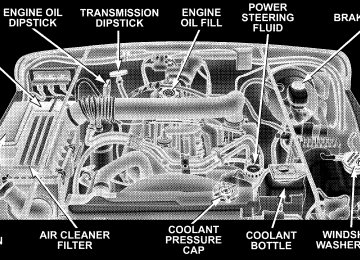
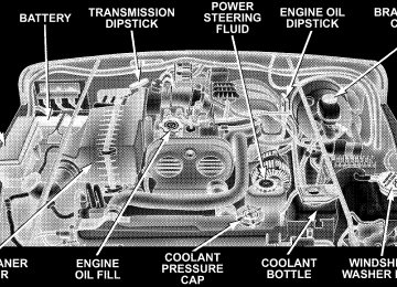
Adding Washer Fluid The fluid reservoir for the windshield washers and the rear window washer is shared. It is located in the front of the engine compartment on the passenger side and should be checked for fluid level at regular intervals. Fill the reservoir with windshield washer solvent (not radia- tor antifreeze) and operate the system for a few seconds to flush out the residual water.
STARTING AND OPERATING
CONTENTS
m Starting Procedures
. . . . . . . . . . . . . . . . . . . . 160
N Manual Transmission . . . . . . . . . . . . . . . . . . 160
N Automatic Transmission . . . . . . . . . . . . . . . . 160
N Normal Starting . . . . . . . . . . . . . . . . . . . . . . 160
N Extreme Cold Weather(Below –20°F Or –29°C) . . . . . . . . . . . . . . . . . 161
N If Engine Fails To Start . . . . . . . . . . . . . . . . . 161
N After Starting . . . . . . . . . . . . . . . . . . . . . . . . 162
m Engine Block Heater — If Equipped . . . . . . . . 162
m Transmission Shifting . . . . . . . . . . . . . . . . . . . 163
N 5-Speed Manual Overdrive Transmission . . . . . 163
N Automatic Transmission . . . . . . . . . . . . . . . . 165m Four–Wheel Drive Operation (Command-Trac™
Or Rock-Trac™) — If Equipped . . . . . . . . . . . 170
N Operating Instructions/Precautions . . . . . . . . . 170
N Shift Positions . . . . . . . . . . . . . . . . . . . . . . . . 171
N Shifting Procedure . . . . . . . . . . . . . . . . . . . . 172
m Trac-Lok™ Rear Axle . . . . . . . . . . . . . . . . . . . 173
m Axle Lock (Tru–Lok™) — If Equipped . . . . . . 174
m Parking Brake . . . . . . . . . . . . . . . . . . . . . . . . . 175
m About Your Brakes . . . . . . . . . . . . . . . . . . . . . 177
m Anti-Lock Brake System — If Equipped . . . . . 179
m On-Road Driving Tips . . . . . . . . . . . . . . . . . . 181158 STARTING AND OPERATING
m Off-Road Driving Tips . . . . . . . . . . . . . . . . . . 181
N When To Use Low Range . . . . . . . . . . . . . . . 181
N In Snow, Mud And Sand . . . . . . . . . . . . . . . . 181
N Hill Climbing . . . . . . . . . . . . . . . . . . . . . . . . 182
N Traction Downhill . . . . . . . . . . . . . . . . . . . . . 183
N After Driving Off-Road . . . . . . . . . . . . . . . . . 183
m Tire Safety Information . . . . . . . . . . . . . . . . . . 184
N Tire Markings . . . . . . . . . . . . . . . . . . . . . . . . 184
N Tire Identification Number (TIN) . . . . . . . . . . 187
N Tire Loading And Tire Pressure . . . . . . . . . . . 188
m Tires — General Information . . . . . . . . . . . . . . 191
N Tire Pressure . . . . . . . . . . . . . . . . . . . . . . . . . 191
N Tire Inflation Pressures . . . . . . . . . . . . . . . . . 192
N High Speed Operation . . . . . . . . . . . . . . . . . 193
N Radial-Ply Tires . . . . . . . . . . . . . . . . . . . . . . 193N Tire Spinning . . . . . . . . . . . . . . . . . . . . . . . . 193
N Tread Wear Indicators . . . . . . . . . . . . . . . . . . 194
N Replacement Tires . . . . . . . . . . . . . . . . . . . . . 194
N Alignment And Balance . . . . . . . . . . . . . . . . . 195
m Tire Chains . . . . . . . . . . . . . . . . . . . . . . . . . . . 196
m Tire Rotation Recommendations . . . . . . . . . . . 196
m Fuel Requirements . . . . . . . . . . . . . . . . . . . . . 197
N Reformulated Gasoline . . . . . . . . . . . . . . . . . 198
N Gasoline/Oxygenate Blends . . . . . . . . . . . . . . 198
N MMT In Gasoline . . . . . . . . . . . . . . . . . . . . . 198
N Sulfur In Gasoline . . . . . . . . . . . . . . . . . . . . . 199
N Materials Added To Fuel . . . . . . . . . . . . . . . . 199
m Fuel Filler Cap (Gas Cap) . . . . . . . . . . . . . . . . 200N Locking Fuel Filler Cap (Gas Cap) —
If Equipped . . . . . . . . . . . . . . . . . . . . . . . . . 202
m Trailer Towing . . . . . . . . . . . . . . . . . . . . . . . . 202
N Warranty Requirements . . . . . . . . . . . . . . . . . 203
m Snow Plow . . . . . . . . . . . . . . . . . . . . . . . . . . . 205
m Recreational Towing(Behind Motorhome, Etc.) . . . . . . . . . . . . . . . . 205
STARTING AND OPERATING 159
N Shifting Into Neutral (N) . . . . . . . . . . . . . . . . 205
N Shifting Out Of Neutral (N) . . . . . . . . . . . . . . 206160 STARTING AND OPERATING
STARTING PROCEDURES Before starting your vehicle, adjust your seat, adjust both inside and outside mirrors, and fasten your seat belts.
WARNING!
Do not leave children or animals inside parked vehicles in hot weather. Interior heat build up may cause serious injury or death.
Manual Transmission Apply the parking brake, place the gearshift control lever in N (Neutral) and depress the clutch pedal before starting vehicle. This vehicle is equipped with a clutch interlocking ignition system. It will not start unless the clutch pedal is pressed to the floor.
WARNING!
You or others around you could be injured if you attempt to start the engine with a manual transmis- sion in gear — your vehicle will move. Remember, always push the clutch pedal in fully and shift into N (Neutral) before attempting to start the engine.
Automatic Transmission Start the engine with the selector lever in the N (Neutral) or P (Park) position. Apply the brake before shifting to any driving range. Normal Starting Normal starting of either a cold or a warm engine is obtained without pumping or depressing the accelerator pedal. Turn the key to the START position and release when the engine starts. If the engine fails to start within 10 seconds, turn the key to the OFF position, wait 5
seconds, then repeat the normal starting procedure.STARTING AND OPERATING 161
CAUTION!
To prevent damage to the starter, do not crank the engine for more than 15 seconds at a time. Wait 10 to 15 seconds before trying again.
If the engine has been flooded, it may start to run, but not have enough power to continue running when the key is released. If this occurs, continue cranking with the accel- erator pedal pushed all the way to the floor. Release the accelerator pedal and the key once the engine is running smoothly. If the engine shows no sign of starting after two 15
second periods of cranking with the accelerator pedal held to the floor, the “Normal Starting” or “Extreme Cold Weather” procedures should be repeated.Extreme Cold Weather (below –20°F or –29°C) To insure reliable starting at these temperatures, use of an externally powered electric engine block heater (available from your dealer) is recommended. If Engine Fails to Start If the engine fails to start after you have followed the “Normal Starting” or “Extreme Cold Weather” proce- dures, it may be flooded. Push the accelerator pedal all the way to the floor and hold it there while cranking the engine. This should clear any excess fuel in case the engine is flooded.
162 STARTING AND OPERATING
WARNING!
Never pour fuel or other flammable liquids into the throttle body air inlet opening in an attempt to start the vehicle. This could result in a flash fire causing serious personal injury.
After Starting The idle speed will automatically decrease as the engine warms up.
CAUTION!
Long periods of engine idling, especially at high engine speeds can cause excessive exhaust tempera- tures which can damage your vehicle. Do not leave your vehicle unattended with the engine running.
ENGINE BLOCK HEATER — IF EQUIPPED The engine block heater warms engine coolant and permits quicker starts in cold weather. Connect the cord to a standard 110-115 volt AC electrical outlet with a grounded, three wire extension cord. The engine block heater cord is found under the hood clipped to the tie rod between the radiator grille and the dash panel.
WARNING!
Remember to disconnect the cord before driving. Damage to the 110-115 volt AC electrical cord could cause electrocution.
Use the heater when temperatures below 0°F (-18°C) are expected to last for several days.
TRANSMISSION SHIFTING
5-Speed Manual Overdrive Transmission Follow the shift pattern on the gearshift knob. NOTE: The backup lights will come on when your vehicle is in reverse gear and the ignition is in the ON position.
STARTING AND OPERATING 163
WARNING!
When parking your vehicle, always leave a manual transmission in first gear and apply the parking brake fully to guard against vehicle movement and possible injury or damage. Never use any gear as a substitute for the parking brake.
CAUTION!
To drive as safely as possible and to prolong the life of your manual transmission, follow these tips: † Before shifting from a forward gear into reverse, or from reverse to a forward gear, stop vehicle com- pletely. Otherwise, transmission damage may result. † Do not operate at sustained high engine or road
speeds in lower gears. Engine damage may result.
164 STARTING AND OPERATING
heat buildup and damages the clutch.
speed requires or the engine may overheat.
† Do not downshift into a low gear while traveling at too high a speed for that gear. Engine, clutch, or transmis- sion damage may result. † Do not rest your foot on the clutch pedal. This causes † When you slow down or go up a grade, downshift as † Never hold the vehicle stopped on a hill by using the † During cold weather, you may experience increased effort in shifting until the transmission fluid warms up. This is normal. † Push in the clutch pedal completely when shifting. Otherwise, transmission or clutch damage may result. † When “rocking” a stuck vehicle by shifting between a forward gear and reverse, do not spin wheels faster than 15 mph (24 km/h), or drivetrain damage may result.
clutch pedal. The clutch may be damaged.
† The manual transmission may be equipped with a “Reverse Blocker” to prevent inadvertent shifts from 5th gear to Reverse. If you experience difficulty shift- ing into “Reverse”, make sure that you are not inad- vertently moving the shift lever toward 5th gear when shifting into “Reverse.”
Recommended Manual Transmission Shifting Speeds The “Shift Indicator Light” in the instrument cluster reminds you when to shift to the next higher gear (4.0L Only). The manufacturer recommends that you use the SIL for normal driving. The desired shift speeds are listed in the chart below. Manual Transmission Shift Speeds in MPH (KM/H) Engine Speeds Accel. 2.4L Cruise Accel. Cruise
1 to 2
15 (24) 15 (24) 14 (23) 14 (23)2 to 3
25 (40) 25 (40) 23 (37) 20 (32)3 to 4
40 (64) 40 (64) 36 (58) 28 (45)4 to 5
45 (72) 45 (72) 44 (71) 38 (61)4.0L
STARTING AND OPERATING 165
Automatic Transmission Shifting from D (Drive) to P (Park) or R (Reverse) (or from P or R to D) should be done only after the accelerator pedal is released and the vehicle is stopped. Be sure to keep your foot on the brake when moving the shift lever between these gears.
Clutch Interlocking Ignition System Manual transmission vehicles are equipped with a clutch interlock safety feature. With this feature engaged, you must depress the clutch pedal to allow cranking of the engine. To temporarily bypass this safety feature while off-road driving, which will allow cranking the engine without depressing the clutch, follow these steps: 1. Locate the instrument panel fuseblock behind the glove compartment. 2. Put a 20 Amp fuse (optional) in the fuseblock cavity (f20) marked as Transmission. NOTE: A fuse is provided in fuseblock cavity (f19) marked as Spare. 3. Be sure to re-engage the clutch interlock safety feature by following these steps in reverse order when you are finished off-road driving.
166 STARTING AND OPERATING
WARNING!
Gear Ranges
P (Park) Supplements the parking brake by locking the trans- mission. The engine can be started in this range. Never use P (Park) while the vehicle is in motion. Apply the parking brake when leaving the vehicle in this range. Always apply the parking brake first, and then place the selector in P (Park) position.
It is dangerous to shift the selector lever out of “P” or “N” if the engine speed is higher than idle speed. If your foot is not firmly on the brake pedal, the vehicle could accelerate quickly forward or in re- verse. You could lose control of the vehicle and hit someone or something. Only shift into gear when the engine is idling normally and when your right foot is firmly on the brake pedal.
Brake Transmission Shift Interlock System This vehicle is equipped with a brake transmission shift interlock system (BTSI) that holds the gearshift lever in the P (Park) position when the ignition switch is in the OFF position. To move the gear selector lever out of the P (Park) position, the ignition switch must be turned to the ON position, the brake pedal and the button on the front of the shifter handle must be depressed.
WARNING!
Unintended movement of a vehicle could injure those in and near the vehicle. As with all vehicles, you should never exit a vehicle while the engine is running. Before exiting a vehicle, you should always shift the vehicle into P (Park), remove the key from the ignition, and apply the parking brake. Once the key is removed from the ignition, the transmission shift lever is locked in the P (Park) position, securing the vehicle against unwanted movement. Further- more, you should never leave children unattended inside a vehicle.
The following indicators should be used to ensure that you have engaged the transmission shift lever into the P (Park) position: † When shifting into P (Park), depress the button on the shift lever and firmly move the lever all the way forward until it stops. † Look at the shift indicator window on the console to
ensure it is in the P (Park) position.
STARTING AND OPERATING 167
† When engaged in P (Park), you will not be able to move the shifter rearward without depressing the shift lever button.
CAUTION!
Before moving the shift lever out of P (Park), you must turn the ignition from LOCK to ON so the steering wheel and shift lever are released. Other- wise, damage to the steering column or shifter could result.
R (Reverse) For moving the vehicle rearward. Always stop before moving the lever to R (Reverse), except when rocking the vehicle. N (Neutral) Engine may be started in this position.
168 STARTING AND OPERATING
WARNING!
Do not coast in N (Neutral) and never turn off the ignition to coast down a hill. These are unsafe practices that limit your response to changing traffic or road conditions. You might lose control of the vehicle.
Overdrive (O/D) For most city and highway driving. The transmission contains an electronically controlled Overdrive, and will automatically shift from D (Drive) to O/D (Over- drive) if the following conditions are present: † The transmission selector is in D (Drive). † The O/D OFF switch has not been activated. † Vehicle speed is above approximately 30 mph (48
km/h).
When frequent transmission shifting occurs while using Overdrive, such as when operating the vehicle under heavy load conditions (for example, in hilly terrain,
strong head winds, or trailer towing), turning off over- drive will improve performance and extend transmission life by reducing excessive shifting and heat buildup.
Overdrive can be locked out by pressing the O/D OFF switch located on the instrument panel. The O/D OFF indicator light (on the switch) will illuminate to show that the switch has been activated. When the indicator light is on, Overdrive is locked out. Pressing the switch a second time restores the Overdrive function. The lockout feature is useful when towing a trailer or carrying a heavy load.
2 (Second) For moderate grades and to assist braking on dry pavement or in mud and snow. Begins at a stop in low gear with automatic upshift to 2nd gear. Will not shift to 3rd. 1 (First) For hard pulling at low speeds in mud, sand, snow, or on steep grades. Begins and stays in low gear with no upshift. Provides engine compression braking at low speeds.
WARNING!
Never use P (Park) position with an automatic trans- mission as a substitute for the parking brake. Al- ways apply parking brake fully when parked to guard against vehicle movement and possible injury or damage.
STARTING AND OPERATING 169
CAUTION!
† Before moving the shift lever out of P (Park), you must turn the ignition from LOCK so the steering wheel and shift lever are released. Otherwise, damage to steering column or shifter could result. † Never race the engine with the brakes on and the vehicle in gear, and never hold the vehicle on an incline without applying the brakes. These prac- tices can overheat and damage the transmission. † When “rocking” a stuck vehicle by moving be- tween D (Drive) and R (Reverse), do not spin the wheels faster than 15 mph (24 km/h), or drivetrain damage may result.
170 STARTING AND OPERATING
Torque Converter Clutch A feature designed to improve fuel economy has been added to the automatic transmission of this vehicle. A clutch within the torque converter engages automatically at calibrated speeds. This may result in a slightly differ- ent feeling or response during normal operation in high gear. When the vehicle speed drops or during accelera- tion, the clutch automatically and smoothly disengages.
FOUR–WHEEL DRIVE OPERATION (COMMAND-TRAC™ OR ROCK-TRAC™) — IF EQUIPPED
Operating Instructions/Precautions The transfer case provides four mode positions — two (rear) wheel drive high range, four wheel drive high range, neutral, and four wheel drive low range. This transfer case is intended to be driven in the two wheel drive (2H) position for normal street and highway conditions such as dry hard surfaced roads. In the events when additional traction is required, the transfer case 4H and 4L positions can be used to lock the front and rear driveshafts together and force the front and rear wheels to rotate at the same speed. This is accomplished by simply moving the shift lever to these positions. The 4H and 4L positions are intended for loose, slippery road surfaces only. Driving in the 4H and 4L positions on dry hard surfaced roads may cause in- creased tire wear and damage to the driveline compo- nents. The 4WD indicator light, located in the instrument panel, alerts the driver that the vehicle is in four wheel drive and that the front and rear driveshafts are locked to- gether. This light illuminates when the transfer case is shifted to either the 4H or 4L positions.
NOTE: Do not attempt to make a shift while only the front or rear wheels are spinning. The transfer case is not equipped with a synchronizer and therefore the front and rear driveshafts speeds must be equal for the shift to take place. Shifting while only the front or rear wheels are spinning can cause damage to the transfer case. When operating your vehicle in 4L, the engine speed is approximately three times that of the 2H or 4H positions at a given road speed. Take care not to overspeed the engine and do not exceed 25 mph (40 km/h). Proper operation of four wheel drive vehicles depends on tires of equal size, type, and circumference on each wheel. Any difference will adversely affect shifting and cause damage to the transfer case. Because four wheel drive provides improved traction, there is a tendency to exceed safe turning and stopping speeds. Do not go faster than road conditions permit.
STARTING AND OPERATING 171
WARNING!
You or others could be injured if you leave the vehicle unattended with the transfer case in the N (Neutral) position without first fully engaging the parking brake. The transfer case N (Neutral) position disengages both the front and rear driveshafts from the powertrain and will allow the vehicle to move regardless of the transmission position. The parking brake should always be applied when the driver is not in the vehicle.
Shift Positions
For additional information on the appropriate use of each transfer case mode position, see the information below: 2H Position Rear Wheel Drive High Range — Normal street and highway driving. Dry hard surfaced roads.
172 STARTING AND OPERATING
4H Position Four Wheel Drive High Range — Locks the front and rear driveshafts together. Forces the front and rear wheels to rotate at the same speed. Additional traction for loose, slippery road surfaces. N (Neutral) Position Neutral — Disengages both the front and rear driveshafts from the powertrain. To be used for flat towing behind another vehicle. Refer to “Recreational Towing” in Sec- tion 5 of this manual. 4L Position Four Wheel Drive Low Range — Locks the front and rear driveshafts together. Forces the front and rear wheels to rotate at the same speed. Additional traction and maxi- mum pulling power for loose, slippery road surfaces only. Do not exceed 25 mph (40 km/h).
Shifting Procedure
2H to 4H or 4H to 2H Shifting between 2H and 4H can be made with the vehicle stopped or in motion. If the vehicle is in motion, shifts can be made up to 55 mph (88 km/h). With the vehicle in motion, the transfer case will engage/ disengage faster if you momentarily release the accelera- tor pedal after completing the shift. Apply a constant force when shifting the transfer case lever. 4H to 4L or 4L to 4H With the vehicle rolling at 2 to 3 mph (3 to 5 km/h), shift an automatic transmission to N (Neutral) or depress the clutch pedal on a manual transmission. While the vehicle is coasting at 2 to 3 mph (3 to 5 km/h), shift the transfer case lever firmly to the desired position. Do not pause in transfer case N (Neutral). NOTE: Pausing in transfer case N (Neutral) in vehicles equipped with an automatic transmission may require shutting the engine OFF to avoid gear clash while completing the shift. If difficulty occurs, shift the auto- matic transmission to N (Neutral), hold foot on brake, and turn the engine OFF. Make shift to desired mode.
NOTE: Shifting into or out of 4L is possible with the vehicle completely stopped, however, difficulty may oc- cur due to the mating teeth not being properly aligned. Several attempts may be required for clutch teeth align- ment and shift completion to occur. The preferred method is with the vehicle rolling at 2 to 3 mph (3 to 5
km/h). Avoid attempting to engage or disengage 4L with the vehicle moving faster than 2 to 3 mph (3 to 5 km/h).WARNING!
Failure to engage a position completely can cause transfer case damage or loss of power and vehicle control. You could have an injury accident. Do not drive the vehicle unless the transfer case is fully engaged.
STARTING AND OPERATING 173
TRAC-LOK™ REAR AXLE The Trac-Lok™ rear axle provides a constant driving force to both rear wheels and reduces wheel spin caused by the loss of traction at one driving wheel. If traction differs between the two rear wheels, the differential automatically proportions the usable torque by providing more torque to the wheel that has traction. Trac-Lok™ is especially helpful during slippery driving conditions. With both rear wheels on a slippery surface, a slight application of the accelerator will supply maxi- mum traction. When starting with only one rear wheel on an excessively slippery surface, slight application of the parking brake may be necessary to gain maximum trac- tion.
174 STARTING AND OPERATING
WARNING!
On vehicles equipped with a limited-slip differen- tial, never run the engine with one rear wheel off the ground. The vehicle may drive through the rear wheel remaining on the ground and cause you to lose control of your vehicle.
AXLE LOCK (TRU–LOK™) — IF EQUIPPED
The Axle Locker switch is located on the lower center of the instrument panel. This feature will only activate when the following conditions are met: † Key in ignition, vehicle in 4L (Low) range. † The vehicle must be traveling at 10 mph (16 km/h) or
less.
To activate the system, press the switch once to lock the rear axle only (the REAR LOCK indicator light will illuminate), press the switch again to lock the front axle (the FRONT LOCK indicator light will illuminate). Once the rear axle is locked, pressing the switch again will lock or unlock the front axle. NOTE: The indicator lights will flash until the axles are fully locked or unlocked. A chime will sound three times and the indicator lights will continue to flash at a different rate if the key is removed while the axles are still in the locked position. To unlock the axles, pull up on the switch.
PARKING BRAKE To set the parking brake, pull the lever up as firmly as possible. When the parking brake is applied with the ignition ON, the BRAKE warning light in the instrument cluster will light. NOTE: The BRAKE warning light indicates only that the parking brake is applied. It does not indicate the degree of brake application. If the parking brake is applied and the vehicle is NOTE: in motion, the BRAKE warning light will flash and a chime will sound.
STARTING AND OPERATING 175
Before leaving the vehicle parked on a hill, you must make sure the parking brake is fully applied and place the gear selector in the P (Park) position (automatic transmission) or first gear (manual transmission). Make certain the transfer case is in gear. Failure to do so may cause the vehicle to roll and cause damage or injury.
WARNING!
† Leaving children unattended in a vehicle is dan- gerous for a number of reasons. A child or others could be injured. Children should be warned not to touch the parking brake or the gear selector lever. Don’t leave the keys in the ignition. A child could operate controls or move the vehicle.
To release the parking brake, pull up slightly, press center button, then lower lever completely.
176 STARTING AND OPERATING
WARNING!
† Always fully apply the parking brake when leav- ing your vehicle, or vehicle may roll and cause damage or injury. Also be certain to leave a automatic transmission in P (Park), or a manual transmission in 1st gear. Make certain the transfer case is in gear. Failure to do so may cause the vehicle to roll and cause damage or injury. † If the parking brake is released, and the BRAKE warning light glows while the ignition switch is ON or the engine is running, there may be a brake system problem. Brake pedal travel, effort and stopping distances may increase, and you should obtain corrective service immediately.
When parking on a hill, it is important to set the parking brake before placing the gear selector in P (Park), other- wise the load on the transmission locking mechanism may make it difficult to move the selector out of P (Park). The parking brake should always be applied when the driver is not in the vehicle.
If the parking brake is not completely released, the BRAKE warning light will remain on. NOTE: Your vehicle has automatically adjusting rear brakes and we do not recommend any adjustment other than the maintenance performed by your authorized dealer.
ABOUT YOUR BRAKES Your vehicle is equipped with power assisted brakes as standard equipment. In the event power assist is lost for any reason (for example, repeated brake applications with the engine off), the brakes will still function. The effort required to brake the vehicle will be much greater than that required with the power system operating.
STARTING AND OPERATING 177
WARNING!
Riding the brakes can lead to brake failure and possibly an accident. Driving with your foot resting or riding on the brake pedal can result in abnormally high brake temperatures, excessive lining wear, and possible brake damage. You wouldn’t have your full braking capacity in an emergency.
If either of two hydraulic systems lose normal capability, the remaining system will still function with some loss of overall braking effectiveness. This will be evident by increased pedal travel during application and greater pedal force required to slow or stop.
178 STARTING AND OPERATING
WARNING!
WARNING!
To use your brakes and decelerate more safely, follow these
tips:† Do not “ride” the brakes by resting your foot on the pedal. † When descending mountains or hills, repeated braking can
This could overheat the brakes and result in unpredictable braking action, longer stopping distances, or brake damage.
cause brake fade with loss of braking control. Avoid repeated heavy braking by downshifting the transmission whenever possible.
† Do not downshift on icy or slippery roads, because engine † Engines may idle at higher speeds during warm-up, which
braking may cause skidding and loss of control.
could cause rear wheels to spin and result in loss of vehicle control. Be especially careful while driving on slippery roads, in close-quarter maneuvering, parking or stopping. Remember, always engage 4-wheel drive when driving on slippery roads.
† Do not drive too fast for road conditions, especially when
roads are wet or slushy. A wedge of water can build up between the tire tread and the road. This hydroplaning action can cause loss of traction, braking ability, and control. Under such conditions, engage 4-wheel drive.
† After going through deep water or a car wash, brakes may
become wet, resulting in poor performance and unpredict- able braking action. Dry the brakes by gentle, intermittent pedal action while driving at very slow speeds.
The weight and position of cargo and passengers can change the vehicle center of gravity and vehicle han- dling. To avoid loss of control resulting in personal injury, follow these guidelines: † Always place cargo evenly on the cargo floor, and locate heavier objects as low and as far forward as possible. † Place as much cargo as possible in front of the rear axle. Too much weight or improperly placed weight over or behind the rear axle can cause the rear of the vehicle to sway. † Do not pile luggage or cargo higher than the top of the seatback. This could impair visibility or become a dangerous projectile in a sudden stop or collision. † The rear cargo space is intended for load carrying purposes only, not for passengers, who should sit in seats and use seat belts. † On hardtop models, do not drive with the lift glass up. On fabric top models, do not drive with the rear window curtain up unless the side curtains are also open. This will prevent dangerous exhaust fumes from entering the vehicle.
STARTING AND OPERATING 179
WARNING!
WARNING!
To help avoid personal injury, follow these tips: † Never reach through the steering wheel to operate steering column controls. Injury to your hands or loss of vehicle control may result. † If the engine stalls or power assist fails due to a malfunction, vehicle steering and braking will require greater effort.
ANTI-LOCK BRAKE SYSTEM — IF EQUIPPED The Anti-Lock Brake System is designed to aid the driver in maintaining vehicle control under adverse braking conditions. The system operates with a separate com- puter to modulate hydraulic pressure to prevent wheel lock-up and help avoid skidding on slippery surfaces. All vehicle wheels and tires must be the same size and type and tires must be properly inflated to produce accurate signals for the computer.
Significant over or under-inflation of tires, or mixing sizes of tires or wheels on the vehicle can lead to loss of braking effectiveness.
The Anti-Lock Brake System conducts a low speed self- test at about 12 mph (20 km/h). If for any reason, your foot is on the brake when the vehicle reaches 12 mph (20
km/h), this check will be delayed until 25 mph (40
km/h). The Anti-Lock Brake System pump motor runs during the self-test and during an ABS stop to provide the regulated hydraulic pressure. The motor pump makes a low humming noise during operation, this is normal. During off-road use, loss of traction can temporarily defeat the system and cause the warning light to illumi- nate. Turn the ignition OFF and ON again to restore Anti-Lock Brake System function.180 STARTING AND OPERATING
WARNING!
WARNING!
Pumping of the Anti-Lock Brakes will diminish their effectiveness and may lead to an accident. Pumping makes the stopping distance longer. Just press firmly on your brake pedal when you need to slow down or stop.
† Anti-lock system (ABS) cannot prevent the natu- ral laws of physics from acting on the vehicle, nor can it increase braking or steering efficiency be- yond that afforded by the condition of the vehicle brakes and tires or the traction afforded.
† The ABS cannot prevent accidents,
including those resulting from excessive speed in turns, following another vehicle too closely, or hydro- planing. Only a safe, attentive, and skillful driver can prevent accidents. † The capabilities of an ABS equipped vehicle must never be exploited in a reckless or dangerous manner which could jeopardize the user’s safety or the safety of others.
CAUTION!
The Anti-Lock Brake System is subject to possible detrimental effects of electronic interference caused by improperly installed aftermarket radios or tele- phones.
NOTE: During severe braking conditions, a pulsing sensation may occur and a clicking noise will be heard. This is normal, the Anti-Lock Brake System is functioning.
indicating that
ON-ROAD DRIVING TIPS Utility vehicles have higher ground clearance and a narrower track to make them capable of performing in a wide variety of off-road applications. Specific design characteristics give them a higher center of gravity than ordinary cars. An advantage of the higher ground clearance is a better view of the road, allowing you to anticipate problems. They are not designed for cornering at the same speeds as
STARTING AND OPERATING 181
conventional 2-wheel drive vehicles any more than low- slung sports cars are designed to perform satisfactorily in off-road conditions. If at all possible, avoid sharp turns or abrupt maneuvers. As with other vehicles of this type, failure to operate this vehicle correctly may result in loss of control or vehicle rollover.
OFF-ROAD DRIVING TIPS
When To Use Low Range When driving off-road, shift to 4L (Low) for additional traction in pulling forward or descending a hill, for low-speed pulling power or to improve handling and control on slippery or difficult terrain. Also use 4L (Low) in rain, ice, snow, mud or sand to get heavy loads rolling, or whenever 4H (High) range four-wheel drive traction will not do the job. In Snow, Mud and Sand In heavy snow, when pulling a load, or for additional control at slower speeds, shift the transmission to a low gear and shift the transfer case to 4L (Low) if necessary.
182 STARTING AND OPERATING
Don’t shift to a lower gear than necessary to maintain headway. Over-revving the engine can spin the wheels and traction will be lost. Do not downshift on icy or slippery roads because engine braking may cause skidding and loss of control. When driving on soft sand, reduce your tire pressure to 15 psi (103 kPa) minimum to allow greater tire surface area. You must return the tires to normal air pressure before driving on pavement or other hard surfaces. NOTE: Reduced tire pressures below 15 psi (103 kPa) may cause tire unseating and loss of air pressure. Hill Climbing Before climbing a steep hill, change transmission to a lower gear and shift the transfer case to 4L (Low). Use first gear and 4L (Low) for very steep hills. If you stall or begin to lose headway while climbing a steep hill, allow your vehicle to come to a stop and immediately apply the brake. Restart the engine and shift to R (Reverse). Back up slowly down the hill allowing the compression braking of the engine and transmission to
help regulate your speed. If the brakes are required to control vehicle speed, apply them lightly and avoid locking or skidding the tires.
WARNING!
If the engine stalls or you lose headway or cannot make it to the top of a steep hill or grade, never attempt to turn around. To do so may result in tipping and rolling the vehicle. Always back care- fully straight down a hill in R (Reverse) gear. Never back down a hill in N (Neutral) or with the clutch pedal depressed, using only the brake.
Remember, never drive diagonally across a hill, always drive straight up or down. If the wheels start to slip as you approach the crest of a hill, ease off the accelerator and maintain headway by turning the front wheels sharply left and right. This will provide fresh “bite” into the surface and will usually provide traction to complete the climb.
Traction Downhill Shift the transmission into a low gear and transfer case to 4L (Low) range. Let the vehicle go slowly down the hill with all four wheels turning against engine compression drag. This will permit you to control the vehicle speed and direction. After Driving Off-Road Off-road operation puts more stress on your vehicle than does most on-road driving. After driving off-road, it is always a good idea to check for damage. † Completely inspect the underbody of your vehicle. Check tires, body structure, steering, suspension, and exhaust system for damage. † Check threaded fasteners for looseness, particularly on the chassis, drivetrain components, steering, and sus- pension. Retighten them, if required, and torque to the values specified in the Service Manual. † Check for accumulations of plants or brush. These things could be a fire hazard, or they might hide damage to fuel lines, brake hoses, axle pinion seals, and propeller shafts.
STARTING AND OPERATING 183
† After extended operation in mud, sand, water, or similar dirty conditions, have brake drums, brake linings, and axle yokes inspected and cleaned as soon as possible.
WARNING!
Abrasive material in any part of the brakes may cause excessive wear or unpredictable braking. You might not have full braking power when you need it to prevent an accident. If you have been operating your vehicle in dirty conditions, get your brakes checked and cleaned as necessary. † If you experience unusual vibration after driving in mud, slush or similar conditions, check the wheels for packed material. Packed foreign material can cause a wheel imbalance and freeing the wheels will correct the situation.
184 STARTING AND OPERATING
TIRE SAFETY INFORMATION
Tire Markings
NOTE: P(Passenger)-Metric tire sizing is based on U.S. design standards. P-Metric tires have the letter “P” molded into the sidewall preceding the size designation. Example: P215/65R15 95H.
NOTE: European Metric tire sizing is based on Euro- pean design standards. Tires designed to this standard have the tire size molded into the sidewall beginning with the section width. The letter 9P9 is absent from this tire size designation. Example: 215/65R15 96H NOTE: LT(Light Truck)-Metric tire sizing is based on U.S. design standards. The size designation for LT-Metric tires is the same as for P-Metric tires except for the letters “LT” that are molded into the sidewall preceding the size designation. Example: LT235/85R16. NOTE: Temporary Spare tires are high pressure com- pact spares designed for temporary emergency use only. Tires designed to this standard have the letter “T” molded into the sidewall preceding the size designation. Example: T145/80D18 103M. NOTE: High Flotation tire sizing is based on U.S. design standards and begins with the tire diameter molded into the sidewall. Example: 31x10.5 R15 LT.
Tire Sizing Chart
Size Designation:
EXAMPLE:
P = Passenger car tire size based on U.S. design standards (....blank....( = Passenger car tire based on European design standards LT = Light Truck tire based on U.S. design standards T = Temporary Spare tire 31 = Overall Diameter in Inches (in) 215 = Section Width in Milimeters (mm) 65 = Aspect Ratio in Percent (%)
—Ratio of section height to section width of tire.
10.5 = Section Width in Inches (in) R = Construction Code
—9R9 means Radial Construction. —9D9 means Diagonal or Bias Construction.
15 = Rim Diameter in Inches (in)
STARTING AND OPERATING 185
186 STARTING AND OPERATING
Service Description:
95 = Load Index
EXAMPLE:
—A numerical code associated with the maximum load a tire can carry.
H = Speed Symbol
—A symbol indicating the range of speeds at which a tire can carry a load corresponding to its load index under certain operating conditions. —The maximum speed corresponding to the Speed Symbol should only be achieved un- der specified operating conditions. (ie. tire pressure, vehicle loading, road conditions and posted speed limits).
Load Identification:
(....blank....( = Absence of any text on sidewall of the tire indicates a Standard Load (SL) Tire Extra Load (XL) = Extra Load (or Reinforced) Tire Light Load = Light Load Tire C,D,E = Load range associated with the maximum load a tire can carry at a specified pressure
Maximum Load — Maximum Load indicates the maximum load this tire is designed to carry. Maximum Pressure — Maximum Pressure indicates the maximum permissible cold tire inflation pressure for this tire.
Tire Identification Number (TIN) The TIN may be found on one or both sides of the tire however the date code may only be on one side. Tires with white sidewalls will have the full TIN including date code located on the white sidewall side of the tire.
STARTING AND OPERATING 187
Look for the TIN on the outboard side of black sidewall tires as mounted on the vehicle. If the TIN is not found on the outboard side then you will find it on the inboard side of the tire.
EXAMPLE:
DOT MA L9 ABCD 0301
DOT = Department of Transportation
—This symbol certifies that the tire is in compliance with the U.S. Department of Transportation tire safety standards, and is approved for highway use.
MA = Code representing the tire manufacturing location.(2 digits) L9 = Code representing the tire size.(2 digits) ABCD = Code used by tire manufacturer.(1 to 4 digits) 03 = Number representing the week in which the tire was manufactured.(2 digits)
—03 means the 3rd week.
01 = Number representing the year in which the tire was manufactured.(2 digits)
—01 means the year 2001. —Prior to July 2000, tire manufacturers were only required to have 1 number to represent the year in which the tire was manufactured. Example: 031 could represent the 3rd week of 1981 or 1991.
188 STARTING AND OPERATING
Tire Loading and Tire Pressure
Tire Placard Location NOTE: The tire placard is located on the lower driver’s side instrument panel. Tire and Loading Information Placard
This placard tells you important information about the, 1) number of people that can be carried in the vehicle 2) the total weight your vehicle can carry
3) the tire size designed for your vehicle 4) the cold tire inflation pressures for the front, rear and spare tires. Loading The vehicle maximum load on the tire must not exceed the load carrying capacity of the tire on your vehicle. You will not exceed the tire’s load carrying capacity if you adhere to the loading conditions, tire size and cold tire inflation pressures specified on the Tire and Loading Information placard and the Vehicle Loading section of this manual. NOTE: Under a maximum loaded vehicle condition, gross axle weight ratings (GAWR’s) for the front and rear axles must not be exceeded. For further information on GAWR’s, vehicle loading and trailer towing, see the Vehicle Loading section of this manual. To determine the maximum loading conditions of your vehicle, locate the statement “The combined weight of occupants and cargo should never exceed XXX kg or XXX lbs.” on the Tire and Loading Information placard. The
combined weight of occupants, cargo/luggage and trailer tongue weight (if applicable) should never exceed the weight referenced here. Steps for Determining Correct Load Limit 1. Locate the statement “The combined weight of occu- pants and cargo should never exceed XXX pounds” on your vehicle’s placard. 2. Determine the combined weight of the driver and passengers that will be riding in your vehicle. 3. Subtract the combined weight of the driver and pas- sengers from XXX kilograms or XXX pounds. 4. The resulting figure equals the available amount of cargo and luggage load capacity. For example, if “XXX” amount equals 1400 lbs. and there will be five 150 lb. passengers in your vehicle, the amount of available cargo and luggage load capacity is 650 lb. (1400–750 (5 x 15) = 650 lb.)
STARTING AND OPERATING 189
5. determine the combined weight of luggage and cargo being loaded on the vehicle. That weight may not safely exceed the available cargo and luggage load capacity calculated in step 4. 6. If your vehicle will be towing a trailer, load from your trailer will be transferred to your vehicle. Consult this manual to determine how this reduces the available cargo and luggage load capacity of your vehicle. NOTE: The following table shows examples on how to calculate total load, cargo/luggage and towing capacities of your vehicle with varying seating configurations and number and size of occupants. This table is for illustra- tion purposes only and may not be accurate for the seating and load carry capacity of your vehicle. NOTE: For the following example the combined weight of occupants and cargo should never exceed 865 lbs. (392
Kg).190 STARTING AND OPERATING
WARNING!
1. Safety—
STARTING AND OPERATING 191
Overloading of your tire is dangerous. Overloading can cause tire failure, affect vehicle handling, and increase your stopping distance. Use tires of the recommended load capacity for your vehicle-never overload them.
TIRES — GENERAL INFORMATION
Tire Pressure Proper tire inflation pressure is essential to the safe and satisfactory operation of your vehicle. Three primary areas are affected by improper tire pressure:
WARNING!
Improperly inflated tires are dangerous and can cause accidents. † Under inflation increases tire flexing and can result in tire failure. † Over inflation reduces a tire’s ability to cushion shock. Objects on the road and chuck holes can cause damage that results in tire failure. † Unequal tire pressures can cause steering prob- lems. You could lose control of your vehicle. † Over inflated or under inflated tires can affect vehicle handling and can fail suddenly, resulting in loss of vehicle control. Always drive with each tire inflated to the recom- mended pressure.
192 STARTING AND OPERATING
2. Economy— Improper inflation pressures can cause uneven wear patterns to develop across the tire tread. These abnormal wear patterns will reduce tread life resulting in a need for earlier tire replacement. Under inflation also increases tire rolling resistance and results in higher fuel consump- tion. 3. Ride Comfort and Vehicle Stability— Proper tire inflation contributes to a comfortable ride. Over inflation produces a jarring and uncomfortable ride. Both under inflation and over inflation affect the stability of the vehicle and can produce a feeling of sluggish response or over-responsiveness in the steering. Unequal tire pressures can cause erratic and unpredict- able steering response. Unequal tire pressure from side to side may cause the vehicle to drift left or right.
Tire Inflation Pressures The proper cold tire inflation pressure is located on the lower driver’s side instrument panel. The tire pressure should be checked and adjusted at least once every month. Check more often if subject to a wide range of outdoor temperatures, as tire pressures vary with temperature changes. Inflation pressures specified on the label are always “Cold Inflation Pressure.” Cold inflation pressure is defined as the tire pressure after the vehicle has been idle for at least 3 hours, or driven less than a mile after a 3
hour period. The cold inflation pressure must not exceed the maximum values molded into the tire sidewall. Tire pressures may increase from 13 to 40 kPa (2 to 6 psi) [0.138 to 0.414 bar] during operation. DO NOT reduce this normal pressure buildup.High Speed Operation
Radial-Ply Tires
STARTING AND OPERATING 193
WARNING!
WARNING!
High speed driving with your vehicle under load is dangerous. The added strain on your tires could cause them to fail. You could have a serious accident. Don’t drive a vehicle loaded to maximum capacity at continuous speeds above 75 mph (120 km/h).
Combining radial ply tires with other types of tires on your vehicle will cause your vehicle to handle poorly. The instability could cause an accident. Al- ways use radial tires in sets of four. Never combine them with other types of tires.
The manufacturer advocates driving at safe speeds within posted speed limits. Where speed limits or condi- tions are such that the vehicle can be driven at high speeds, correct tire inflation pressure is very important.
Cuts and punctures in radial tires are repairable only in the tread area because of sidewall flexing. Consult your dealer for radial tire repairs. Tire Spinning When stuck in mud, sand, snow, or ice conditions, do not spin your vehicle’s wheels above 35 mph (55 km/h).
194 STARTING AND OPERATING
WARNING!
Fast spinning tires can be dangerous. Forces gener- ated by excessive wheel speeds may cause tire dam- age or failure. A tire could explode and injure someone. Do not spin your vehicle’s wheels faster than 35 mph (55km/h) when you are stuck. And don’t let anyone near a spinning wheel, no matter what the speed.
Tread Wear Indicators
These indicators are narrow strips 1/16 inch (1.6 mm) thick and are found in the tread pattern grooves. When the tread pattern is worn down to these treadwear indicators, the tires should be replaced. Overloading your vehicle, long trips in very hot weather, and driving on bad roads may result in greater wear. Replacement Tires The tires on your new vehicle provide a balance of many characteristics. They should be inspected regularly for wear and correct inflation pressure. The manufacturer strongly recommends that you use tires equivalent to the originals in quality and performance when replacement is needed (see section on tread wear indicators). Failure to use equivalent replacement tires may adversely affect the safety, handling and ride of your vehicle. We recom- mend that you contact your original equipment tire dealer on any questions you may have on tire specifica- tions or capability.
WARNING!
† Do not use a tire, wheel size or rating other than that specified for your vehicle. Some combinations of unapproved tires and wheels may change suspen- sion dimensions and performance characteristics, resulting in changes to steering, handling, and brak- ing of your vehicle. This can cause unpredictable handling and stress to steering and suspension com- ponents. You could lose control and have an accident resulting in serious injury or death. Use only the tire and wheel sizes with load ratings approved for your vehicle. † Never use a tire smaller than the minimum tire size listed on your vehicle’s tire label. Using a smaller tire could result in tire overloading and failure. You could lose control and have an accident. † Failure to equip your vehicle with tires having adequate speed capability can result in sudden tire failure and loss of vehicle control. † Overloading your tires is dangerous. Overloading can cause tire failure. Use tires of the recommended load capacity for your vehicle - never overload them.
STARTING AND OPERATING 195
CAUTION!
Replacing original tires with tires of a different size may result in false speedometer and odometer read- ings. Check with your dealer before replacing tires with a different size.
Alignment And Balance Tire suspension components of your vehicle should be inspected and aligned when needed, to obtain maximum tire tread life. Poor suspension alignment may result in: † reduced tread life; † uneven tire wear, such as feathering and one-sided † vehicle pull to the right or to the left. Tires may also cause your vehicle to pull to the left or right. Alignment won’t correct this condition. See your dealer for proper diagnosis.
wear,
196 STARTING AND OPERATING
Improper alignment will not cause vehicle vibration, which may be a result of tire and wheel out-of-balance. Proper balancing will reduce vibration and avoid tire cupping and spotty wear.
TIRE CHAINS Install chains on rear tires only. Tire chains may be installed on all models except Sahara. Follow these recommendations to guard against damage and exces- sive tire and chain wear: † Use chains on P205/75R15 or P215/75R15 tires only. P225/75R15, LT30 x 9.50R15, and LT245/75R16 tires do not provide adequate clearance. † Use SAE class “S” tire chains or traction devices only. † Chains must be the proper size for the vehicle, as † Follow tire chain manufacturer’s instructions for † Install chains snugly and tighten after.6 mile (1 km) of
recommended by the chain manufacturer.
mounting chains.
driving.
† Do not exceed 30 mph (48 km/h). † Drive cautiously, avoiding large bumps, potholes and † Do not use chains or traction devices on the Poly-spare
extreme driving maneuvers.
tire.
TIRE ROTATION RECOMMENDATIONS Tires on the front and rear axles of vehicles operate at different loads and perform different steering, handling, and braking functions. For these reasons, they wear at unequal rates, and develop irregular wear patterns. These effects can be reduced by timely rotation of tires. The benefits of rotation are especially worthwhile with aggressive tread designs such as those on On/Off Road type tires. Rotation will increase tread life, help to main- tain mud, snow, and wet traction levels, and contribute to a smooth, quiet ride.
Follow the recommended tire rotation frequency for your type of driving found in the “Maintenance Schedules” Section of this manual. More frequent rotation is permis- sible if desired. The reasons for any rapid or unusual wear should be corrected prior to rotation being per- formed. The suggested rotation method is the “forward-cross” shown in the following diagram.
STARTING AND OPERATING 197
FUEL REQUIREMENTS
Your engine is designed to meet all emis- sions regulations and provide excellent fuel economy and performance when us- ing high quality unleaded gasoline having an octane rating of 87. The use of premium gasoline is not recommended. The use of premium gasoline will provide no benefit over high quality regular gasoline, and in some circumstances may result in poorer performance. Light spark knock at low engine speeds is not harmful to your engine. However, continued heavy spark knock at high speeds can cause damage and immediate service is required. Engine damage resulting from operation with a heavy spark knock may not be covered by the new vehicle warranty. Poor quality gasoline can cause problems such as hard starting, stalling and hesitations. If you experience these symptoms, try another brand of gasoline before consid- ering service for the vehicle.
198 STARTING AND OPERATING
Over 40 auto manufacturer’s world wide have issued and endorsed consistent gasoline specifications (the World- wide Fuel Charter, WWFC) to define fuel properties necessary to deliver enhanced emissions, performance, and durability for your vehicle. The manufacturer recom- mends the use of gasoline that meets the WWFC speci- fications if they are available. Reformulated Gasoline Many areas of the country require the use of cleaner burning gasoline referred to as Reformulated Gasoline. Reformulated gasoline contains oxygenates, and is spe- cifically blended to reduce vehicle emissions and im- prove air quality. The manufacturer strongly supports the use of reformu- lated gasoline. Properly blended reformulated gasoline will provide excellent performance and durability for the engine and fuel system components. Gasoline/Oxygenate Blends Some fuel suppliers blend unleaded gasoline with oxy- genates such as 10% ethanol, MTBE, and ETBE. Oxygen- ates are required in some areas of the country during the
winter months to reduce carbon monoxide emissions. Fuels blended with these oxygenates may be used in your vehicle.
CAUTION!
DO NOT use gasoline containing METHANOL. Gasoline containing methanol may damage critical fuel system components.
MMT In Gasoline MMT is a manganese containing metallic additive that is blended into some gasoline to increase octane. Gasoline blended with MMT provides no performance advantage beyond gasoline of the same octane number without MMT. Gasoline blended with MMT reduces spark plug life and reduces emission system performance in some vehicles. The manufacturer recommends that gasoline without MMT be used in your vehicle. The MMT content of gasoline may not be indicated on the gasoline pump, therefore, you should ask your gasoline retailer whether or not his/her gasoline contains MMT.
STARTING AND OPERATING 199
CAUTION!
If the “Malfunction Indicator Light” is flashing, immediate service is required. See “Onboard Diag- nostic System” in Section 7 of this manual.
Materials Added To Fuel All gasoline sold in the United States is required to contain effective detergent additives. Use of additional detergents or other additives is not needed under normal conditions.
It is even more important to look for gasoline without MMT in Canada because MMT can be used at levels higher than allowed in the United States. MMT is pro- hibited in Federal and California reformulated gasoline. Sulfur In Gasoline If you live in the northeast United States, your vehicle may have been designed to meet California low emission standards with clean burning, low sulfur, California gasoline. Gasoline sold outside of California is permitted to have higher sulfur levels which may affect the perfor- mance of the vehicle’s catalytic converter. This may cause the “Malfunction Indicator Light” to illuminate. Illumination of this light while operating on high sulfur gasoline does not necessarily mean your emission control system is malfunctioning. The manufacturer recom- mends that you try a different brand of unleaded gaso- line having lower sulfur to determine if the problem is fuel related prior to returning your vehicle to an autho- rized dealer for service.
200 STARTING AND OPERATING
FUEL FILLER CAP (GAS CAP) The fuel cap is located on the left side of the vehicle. If the fuel cap is lost or damaged, be sure the replacement cap is for use with this vehicle.
CAUTION!
Damage to the fuel system or emission control system could result from using an improper fuel cap (gas cap). A poorly fitting cap could let impurities into the fuel system. Also, a poorly fitting after- market cap can cause the MIL (Malfunction Indica- tor Light) to illuminate, due to fuel vapors escaping from the system. † Turn the engine off. † Rotate the fuel cap to the left to remove. † To replace the cap, insert it into the filler neck and tighten the cap about 1/4 turn until you hear one click. This is an indication that the cap is properly tightened. † Make sure that the fuel cap tether strap is not caught
under the fuel cap.
CAUTION!
To avoid fuel spillage and overfilling, do not “top off” the fuel tank after filling.
NOTE: When the fuel nozzle “clicks” or shuts off, the fuel tank is full.
STARTING AND OPERATING 201
WARNING!
† Remove the fuel cap (gas cap) slowly to prevent fuel spray from the filler neck which may cause injury. † The volatility of some gasoline may cause a buildup of pressure in the fuel tank that may increase while you drive. This pressure can result in a spray of gasoline and/or vapors when the cap is removed from a hot vehicle. Removing the cap slowly allows the pressure to vent and prevents fuel spray. † Never have any smoking materials lit in or near the vehicle when the fuel cap is removed or the tank filled. † Never add fuel to the vehicle when the engine is
running.
202 STARTING AND OPERATING
WARNING!
A fire may result if gasoline is pumped into a portable container that is inside of a vehicle. You could be burned. Always place gas containers on the ground while filling.
Locking Fuel Filler Cap (Gas Cap) — If Equipped † Turn the engine off. † Insert the ignition key into the fuel cap, and turn the key to the right to unlock the fuel cap. Rotate the fuel cap to the left to remove. † To replace the cap, insert it into the filler neck and tighten the cap about 1/4 turn until you hear one click. This is an indication that the cap is properly tightened. † Make sure that the fuel cap tether strap is not caught † Be sure to remove the key.
under the fuel cap.
CAUTION!
To avoid fuel spillage and overfilling, do not “top off” the fuel tank after filling.
NOTE: When the fuel nozzle “clicks” or shuts off, the fuel tank is full.
TRAILER TOWING In this section you will find information on limits to the type of towing you can reasonably do with your vehicle. Before towing a trailer, carefully review this information to tow your load as efficiently and safely as possible. To maintain warranty coverage, follow the requirements and recommendations in this manual concerning ve- hicles used for trailer towing. Perform maintenance services as prescribed in the “Maintenance Schedules” section. When your vehicle is used for trailer towing, never exceed the gross axle weight rating (GAWR) by the addition of: † The tongue weight of the trailer.
† The weight of any other type of cargo or equipment
put in or on your vehicle.
Remember that everything put in or on the trailer adds to the load on your vehicle. Warranty Requirements The manufacturer’s warranty will apply to vehicles used to tow trailers for noncommercial use, however the following conditions must be met: † The “D” Overdrive range can be selected when tow- ing. However, if frequent shifting occurs move the shift lever to the next lower position to eliminate excessive automatic transmission shifting. This action will also reduce the possibility of transmission over- heating and provide better engine braking. Refer to “Transmission Shifting” in this section for additional information. † A load equalizing hitch is recommended for loaded
trailer weights above 1,000 lbs (454 kg).
STARTING AND OPERATING 203
CAUTION!
If the trailer weighs more than 1,000 lbs (454 kg) loaded, it should have its own brakes and they should be of adequate capacity. Failure to do this could lead to accelerated brake lining wear, higher brake pedal effort, and longer stopping distances.
WARNING!
Connecting trailer brakes to your vehicle’s hydraulic brake lines can overload your brake system and cause it to fail. You might not have brakes when you need them and could have an accident. † Whenever you pull a trailer, regardless of the trailer size, stop lights and turn signals on the trailer are mandatory for motoring safety. † Follow the maintenance intervals in schedule “B” for changing the automatic transmission fluid and filter, if you REGULARLY tow a trailer for more than 45
minutes of continuous operation.204 STARTING AND OPERATING
NOTE: Refer to “Recommended Fluids, Lubricants, and Genuine Parts” in Section 7 for axle differential lubrication specifications for towing.
SNOW PLOW Snow plows should not be added to the front end of your vehicle.