- 2011 Jeep Wrangler Owners Manuals
- Jeep Wrangler Owners Manuals
- 2005 Jeep Wrangler Owners Manuals
- Jeep Wrangler Owners Manuals
- 2006 Jeep Wrangler Owners Manuals
- Jeep Wrangler Owners Manuals
- 2004 Jeep Wrangler Owners Manuals
- Jeep Wrangler Owners Manuals
- 2013 Jeep Wrangler Owners Manuals
- Jeep Wrangler Owners Manuals
- 2009 Jeep Wrangler Owners Manuals
- Jeep Wrangler Owners Manuals
- 2008 Jeep Wrangler Owners Manuals
- Jeep Wrangler Owners Manuals
- 2012 Jeep Wrangler Owners Manuals
- Jeep Wrangler Owners Manuals
- 2010 Jeep Wrangler Owners Manuals
- Jeep Wrangler Owners Manuals
- 2007 Jeep Wrangler Owners Manuals
- Jeep Wrangler Owners Manuals
- Download PDF Manual
-
(toward rear of vehicle). The mirror should be adjusted while set in the day position (toward windshield).
UNDERSTANDING THE FEATURES OF YOUR VEHICLE 47
Each time the center button is pressed and released within 3 seconds, the display toggles through the follow- ing three configurations: † display compass/temperature (Fahrenheit), † display compass/temperature (Celsius), † and display off. Compass Calibration
Automatic Calibration Once calibrated, the compass has the ability to self- correct for changes in magnetic field to keep the compass accurate. This is referred to as Automatic Calibration. If magnetic field changes are too great, the compass will enter CAL mode on it’s own and manual calibration will be required. To recalibrate the compass, drive the vehicle at less than 5 mph (8 km/h) through up to 11⁄2 360° turns in an area free from large metal objects or power lines. When the compass has been calibrated, the CAL symbol will turn off and the compass will function normally.
CAUTION!
To avoid damage to the mirror during cleaning, never spray any cleaning solution directly onto the mirror. Apply the solution onto a clean cloth and wipe the mirror clean.
The compass/temperature display provides the outside temperature and one of eight compass headings (N, NE, E, SE, S, SW, W, NW).
free from large metal objects or power lines. When the compass has been calibrated, the CAL symbol will turn off and the compass will function normally. Compass Variation Adjustment Compass Variance is the difference between magnetic north and geographic north. In some areas of the country, the difference between magnetic and geographic north is great enough to cause the compass to give false readings. If this occurs, the compass variance must be set according to the Compass Variance Map. NOTE: When the mirror is in the VAR mode, the letter “Z” will be displayed along with the currently selected zone number.
48 UNDERSTANDING THE FEATURES OF YOUR VEHICLE
When the vehicle is new, the compass should initially be verified for correct compass variance (refer to Compass Variation Adjustment) and calibrated manually (refer to Manual Calibration). This will ensure correct initial cali- bration and eliminate initial erroneous compass head- ings. Manual Calibration If the compass appears erratic and CAL does not appear, you must manually put the compass into the calibration mode. To ensure proper compass calibration, make sure the compass variance is properly set before manually calibrating the compass (refer to Compass Variation Adjustment). To put the compass into calibration mode: Turn the ignition to the ON position. Press and hold the center button for more than 6 seconds until CAL (calibration mode) appears in the display. To change the display between VAR (compass variance) and CAL (compass calibration) modes. Release the button to invoke manual calibration mode. To recalibrate the compass, drive the vehicle at less than 5 mph (8 km/h) through up to CAL should display for a complete 11⁄2 360° turns in an area
UNDERSTANDING THE FEATURES OF YOUR VEHICLE 49
To set the variance: Turn the ignition ON, and press and hold the center button for 3 to 6 seconds. The last variance zone number will be displayed. Each press of the center button will select a new variance zone. When the proper zone is selected, wait 5 seconds to resume normal operation. Outside Mirrors To receive maximum benefit, adjust the outside mirror(s) to center on the adjacent lane of traffic with a slight overlap of the view obtained on the inside mirror.
50 UNDERSTANDING THE FEATURES OF YOUR VEHICLE
WARNING!
† Vehicles and other objects seen in the right side convex mirror will look smaller and f arther away than they really are. Relying too much on your right side mirror could cause you to collide with another vehicle or other object. † Use your inside mirror when judging the size or distance of a vehicle seen in the right side mirror.
SEATS
WARNING!
Adjusting a seat while the vehicle is moving is dangerous. The sudden movement of the seat could cause you to lose control. The seat belt might not be properly adjusted and you could be injured. Adjust any seat only while the vehicle is parked.
Front Seat Adjustment Move seat forward or rearward by lifting the lever. Be sure the latch engages fully.
Front Seat Adjustment — Recline To adjust seatback, lift lever, lean back, and release lever at desired position. To return seatback, lift the lever, lean forward and release the lever.
UNDERSTANDING THE FEATURES OF YOUR VEHICLE 51
Tilting Front Seats Push the lever upward on the seatback to tilt the entire seat forward.
WARNING!
Do not ride with the seatback reclined so that the shoulder belt is no longer resting against your chest. In a collision you could slide under the seat belt and be seriously or even fatally injured. Use the recliner only when the vehicle is parked.
52 UNDERSTANDING THE FEATURES OF YOUR VEHICLE
Fold And Tumble Rear Seat To expand the cargo area: 1. Slide seat belts through the seat cushions into the cargo area. 2. Lift the seatback release lever and fold seatback for- ward.
3. Slowly flip the entire seat forward.
4. Secure the seat with the strap. Wrap strap around sport bar, and put one end of the strap through loop of the other end. Pull to tighten strap around sport bar. Place the opposite loop around hook of seat. Route the strap so that it is between the plates of the seat to eliminate slack and increase tension, as shown.
UNDERSTANDING THE FEATURES OF YOUR VEHICLE 53
Removing the Rear Seat
WARNING!
† It is extremely dangerous to ride in a cargo area, inside or outside of a vehicle. In a collision people riding in these areas are more likely to be seri- ously injured or killed. † Do not allow people to ride in any area of your vehicle that is not equipped with seats and seat belts. † Be sure everyone in your vehicle is in a seat and
using a seat belt properly.
5. When completed, return seat to it’s normal position.
54 UNDERSTANDING THE FEATURES OF YOUR VEHICLE
† First fold the rear seat forward following steps 1
through 3 under “Fold and Tumble Rear Seat” in this section. † Press down on release bar on each side, and pull seat † Remove seat from the vehicle.out and away from lower bracket.
Replacing the Rear Seat Reverse steps for removing the seat. Be certain to pull the seat belts between the seat cushion and seatback. Position them for passenger use.
WARNING!
† To help protect against personal injury, passen- gers should not be seated in the rear cargo area with the rear seat folded down or removed from the vehicle. † The rear cargo space is intended for load carrying purposes only, not for passengers, who should sit in seats and use seat belts.
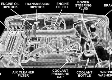
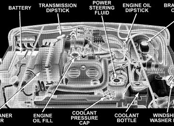
TO OPEN AND CLOSE THE HOOD To open hood, first release both hood latches.
UNDERSTANDING THE FEATURES OF YOUR VEHICLE 55
Next, locate handle in middle of the front end of the hood. Insert hand into gap between hood and radiator support and lift up on handle to raise hood. You may have to push down slightly on hood before lifting up on handle. Insert the support rod into the slot in the radiator support.
To close the hood, remove the support rod from the radiator support and place it in the retaining clip. Lower the hood slowly, then let it drop the last few inches. Secure both of the hood latches.
56 UNDERSTANDING THE FEATURES OF YOUR VEHICLE
WARNING!
If the hood is not fully latched, it could fly up when the vehicle is moving and block your forward vision. Be sure all hood latches are latched fully before driving.
LIGHTS
Interior Lights The overhead light comes on when a door is opened. It may also be turned on by rotating the control for the dimmer switch on the muti-function control lever fully upward. The overhead light will automatically turn off in about 20
minutes if a door is left open or the dimmer control is left in the dome light position. Turn the ignition switch ON to restore the overhead light operation.Daytime Brightness Feature Certain instrument panel components (odometer, radio display) can be illuminated at full brightness during the daytime. This can be helpful when driving with your headlights on during the daytime such as in a parade or a funeral procession. To activate this feature, rotate the left stalk one detent lower than the dome light. Multi-Function Control Lever The multi-function control lever controls the operation of the parking lights, headlights, headlight beam selection, passing light, fog lights, instrument panel light dimming, and turn signals.
Parking Lights, Instrument Panel Lights, and Headlights Turn the end of the multi-function control lever to the first detent for parking lights and instrument panel lights. Turn to the second detent for headlight operation.
To change the brightness of the instrument panel lights, rotate the center portion of the muti-function control lever up or down.
UNDERSTANDING THE FEATURES OF YOUR VEHICLE 57
If the driver’s door is left open, and the head- NOTE: lights or parking lights are left on, the “High Beam Indicator Light” will flash and a chime will sound. Lights-On Reminder If the headlights or parking lights are on after the ignition is turned off, a chime will sound when the driver’s door is opened. Headlight Dimmer Switch Pull the multi-function control lever towards you to switch the headlights to HIGH beam. Pull the muti- function control lever a second time to switch the head- lights to LOW beam. Passing Light You can signal another vehicle with your headlights by lightly pulling the multi-function control lever toward the steering wheel. This will cause the headlights to turn on at high beam and remain on until the lever is released.
58 UNDERSTANDING THE FEATURES OF YOUR VEHICLE
Front Fog Lights — If Equipped
The front fog light switch is in the multi-function control lever. To activate the front fog lights, turn on the parking or low beam headlights and pull
out the end of the lever. NOTE: The fog lights will only operate with the park- ing lights or the headlights on low beam. Selecting high beam headlights will turn off the fog lights. Turn Signals Move the multi-function control lever up or down and the arrows on each side of the instrument cluster flash to show proper operation of the front and rear turn signal lights. You can signal a lane change by moving the lever partially up or down without moving beyond the detent. If either light remains on and does not flash, or there is a very fast flash rate, check for a defective outside light bulb. If an indicator fails to light when the lever is moved, it would suggest that the fuse or indicator bulb is defective. NOTE: A tone will chime if the turn signals are left on for more than 1 mile (2 km).
Daytime Running Lights — Canada Only The headlights come on at a low intensity level after the vehicle has been driven approximately 3 feet (1 meter). They will turn off when the vehicle is turned off or when the headlights are switched on.
WINDSHIELD WIPERS AND WASHERS
CAUTION!
In cold weather, always turn off the wiper switch and allow the wipers to return to the park position before turning off the engine. If the wiper switch is left on and the wipers freeze to the windshield, damage to the wiper motor may occur when the vehicle is restarted.
Intermittent Wiper System Use the intermittent wiper when weather conditions make a single wiping cycle, with a variable pause be- tween cycles, desirable. Move the lever to the DELAY position, then select the delay interval by turning the end
of the lever. The delay can be regulated from a maximum of approximately 18 seconds between cycles, to a cycle every second. Windshield Wiper Operation Move the lever upward to the second detent for LO speed wiper operation, or to the third detent for HI speed operation
UNDERSTANDING THE FEATURES OF YOUR VEHICLE 59
Windshield Washers To use the washer, pull the lever toward you and hold while spray is desired. If the lever is pulled while in the delay range, the wiper will operate for two wipe cycles after the lever is released, and then resume the intermit- tent interval previously selected. If the lever is pulled while in the OFF position, the wipers will operate for as long as the lever is held plus two wipe cycles, then turn OFF. Mist Feature Push down on the wiper lever to activate a single wipe to clear off road mist or spray from a passing vehicle. As long as the lever is held down, the wipers will continue to operate.
60 UNDERSTANDING THE FEATURES OF YOUR VEHICLE
TILT STEERING COLUMN To tilt the column, push down on the lever below the turn signal control and move the wheel up or down, as desired. Pull the lever back upwards to lock the column firmly in place.
WARNING!
Tilting the steering column while the vehicle is moving is dangerous. Without a stable steering col- umn, you could lose control of the vehicle and have an accident. Adjust the column only while the ve- hicle is stopped. Be sure it is locked before driving.
ELECTRONIC SPEED CONTROL When engaged, this device takes over accelerator opera- tions at speeds greater than 35 mph (60 km/h). The controls are mounted on the steering wheel and consist of ON·OFF, SET, RESUME/ACCEL, CANCEL, and COAST controls.
UNDERSTANDING THE FEATURES OF YOUR VEHICLE 61
To Deactivate
A soft tap on the brake pedal, normal braking, or pressing the CANCEL button will deactivate the Speed Control without erasing the memory. Pressing the ON·OFF but- ton or turning off the ignition erases the memory. To Resume Speed To resume a previously set speed, press and release the RESUME/ACCEL button. Resume can be used at any speed above 30 mph (50 km/h). To Vary The Speed Setting When the Speed Control is on and set, speed can be increased by pressing and holding the RESUME/ACCEL button. When the button is released, a new set speed will be established. Tapping the RESUME/ACCEL button once will result in a 2 mph (3 km/h) speed increase. Each time the button is tapped, speed increases, so tapping the button three times will increase speed by 6 mph (9 km/h), etc. To decrease speed while speed control is on and set, press and hold the COAST button. Release the button when the desired speed is reached, and the new speed will be set.
To Activate Press and release the ON·OFF button to turn the system on. To turn the system off, press the ON·OFF button again. The system should be turned off when not in use. The CRUISE indicator light in the instrument cluster illuminates when the system is on. To Set At A Desired Speed When the vehicle has reached the desired speed, press and release the SET button. Release the accelerator and the vehicle will operate at the selected speed.
CIGAR LIGHTER AND ASHTRAYS — IF EQUIPPED The vehicle may be equipped with a cigar lighter recep- tacle, element, and ashtray (Smoker’s Package Only). The cigar lighter will be located in the lower instrument panel (near the heater controls), and the removable ashtray will be located in the center console.
62 UNDERSTANDING THE FEATURES OF YOUR VEHICLE
To Accelerate for Passing Depress the accelerator as you would normally. When the pedal is released, the vehicle will return to the set speed. NOTE: When driving uphill, at elevations above 2,000
ft. (610 meters), or when the vehicle is heavily loaded (especially when towing) the vehicle may slow below the SET speed. (If the vehicle speed drops below 30 mph (48
km/h), the Speed Control will automatically disengage). If this happens, you can push down on the accelerator pedal to maintain the desired speed.WARNING!
Leaving the Speed Control on when not in use is dangerous. You could accidentally set the system or cause it to go faster than you want. You could lose control and have an accident. Always turn the system off when you are not using it.
ELECTRICAL POWER OUTLET To the right of the cigar lighter (if equipped) is the 12 volt power outlet. The outlet is connected directly to the battery, items plugged into this outlet may discharge the battery and/or prevent engine starting. The outlet in- cludes a tethered cap labeled with a battery symbol indicating the power source.
UNDERSTANDING THE FEATURES OF YOUR VEHICLE 63
Electrical Outlet Use With Engine Off
WARNING!
† Many accessories that can be plugged in draw power from the vehicle’s battery, even when not in use (i.e. cellular phones, etc.). Eventually, if plugged in long enough, the vehicle’s battery will discharge sufficiently to degrade battery life and/or prevent engine starting. † Accessories that draw higher power (i.e. coolers, vacuum cleaners, lights, etc.), will degrade the battery even more quickly. Only use these inter- mittently and with greater caution. † After the use of high power draw accessories, or long periods of the vehicle not being started (with accessories still plugged in), the vehicle must be driven a sufficient length of time to allow the alternator to recharge the vehicle’s battery. † Power outlets are designed for accessory plugs only. Do not hang any type of accessory or acces- sory bracket from the plug. Improper use of the power outlet can cause damage not covered by your warranty.
64 UNDERSTANDING THE FEATURES OF YOUR VEHICLE
CUP HOLDERS In the center console there are two cup holders for the front seat passengers. NOTE: The cup holder insert is removable from the console, for cleaning.
The rear passengers have cup holders at the rear of the center console.
STORAGE
Glove Compartment To unlock the glove compartment, insert the key and turn. To open, pull the latch up.
UNDERSTANDING THE FEATURES OF YOUR VEHICLE 65
Console Storage Compartment — If Equipped To unlock, insert key and turn. To open, press the latch button.
Add-A-Trunk™ — If Equipped The factory-installed Add-A-Trunk™ option provides a secured compartment for parcels or equipment when the tailgate is closed and locked. To gain access to this compartment, simply open the tailgate and release the spring loaded latch pins. The cover of the Add-A- Trunk™ can then be raised.
66 UNDERSTANDING THE FEATURES OF YOUR VEHICLE
When the Add-A-Trunk™ is not desired, it can be easily removed from the rear compartment. Remove the four knobs that secure the “trunk” to the body. Lift the Add-A-Trunk™ out and place the knobs in the molded-in storage area. Storage space is also provided for the wheel lock, and lock key tool. Do not leave the Add-A-Trunk™ loose in your vehicle. Remove it and store it in a safe place.
DUAL TOP — IF EQUIPPED If your vehicle is equipped with a Dual Top, you must remove one of the tops from the vehicle. The soft top was installed at the factory for shipping purposes only. The soft top and the hard top are to be used indepen- dently. Removal is mandatory to prevent any possible wear and tear on the soft top, should both tops remain on the vehicle at the same time. Failure to do so may void your soft top warranty.
Removing The Soft Top
1. Locate and remove the 2 boxes that contain the following items: † right and left door frames † door frame attachment knobs (4) † right and left quarter windows † rear tailgate window 2. Remove the hard top. Refer to “Hard Top Removal” in this section. 3. Remove the soft top bow assembly pivot bracket screws (2 per side) using a #30 Torxt head driver.
4. Using a rubber mallet, carefully tap the knuckles from the outside edge. This will remove the bow assembly from the pivot bracket. Remove the soft top from the vehicle and store in a clean, dry location.
UNDERSTANDING THE FEATURES OF YOUR VEHICLE 67
68 UNDERSTANDING THE FEATURES OF YOUR VEHICLE
5. Unzip the zipper on the sport bar cover to expose the pivot bracket. Remove the brackets using a #T40 Torxt head driver. Recover and re-zip the sports bar cover. Store pivot brackets and screws in a safe place.
6. Reinstall the hard top. Refer to “Hard Top Installation” in this section. Installing the Soft Top
NOTE: The following procedures are for first time set up only. For future soft top procedures, refer to “Soft Top” in this section.
1. Locate and remove the following items prior to hard top removal: † right and left door frames † door frame attachment knobs (4) † right and left quarter windows † rear tailgate window. 2. Remove the hard top. Refer to “Hard Top Removal” in this section. 3. Install the door frames. Refer to “Door Frame” in this section. 4. If the soft top has been removed, follow these steps to reinstall the soft top. If the soft top is on the vehicle, proceed to step #4.
a. If the pivot brackets have been removed, unzip the sport bar cover and attach the pivot brackets and screws with a #T40 Torxt head driver. Re-cover and re-zip sport bar cover. b. If the door frames have been removed, re-install them (refer to “Door Frame” in this section).
c. Lay the soft top back into the vehicle with the curved portion of the bows facing upward. d. Tap the knuckles on the side with a rubber mallet to reattach them to the pivot bracket. e. Screw the pivot screws back into place. Secure them until they are snug being careful not to cross- thread the screws.
UNDERSTANDING THE FEATURES OF YOUR VEHICLE 69
CAUTION!
Do not overtighten the screws. You can strip the screws if they are overtightened.
5. Unsnap and remove the black boot cover. This cover should be discarded. It was intended as a protective cover for shipping only. NOTE: A visual instruction sheet is enclosed in the dual top wrap.
70 UNDERSTANDING THE FEATURES OF YOUR VEHICLE
6. Open the tailgate. 7. Remove the tailgate bar (black bar with end caps) that is located in the soft top and set aside. NOTE: Be sure the wire harness is not attached to the soft top bows before you lift the top. 8. Lift the soft top fabric up and away from the plastic header with latches. 9. Pull all of the soft top fabric toward the rear of the vehicle and wrap around the plastic header. 10. Pull the soft top fabric around the ends of the plastic header so that the fabric has a tight, smooth appearance. 11. Working from the rear of the vehicle with the tailgate open, lift the plastic header up and over the sport bar. As the header reaches the top, locate the 2 bow and push it up and over the sport bar.
12. Move to the side of the vehicle and pull the side bow forward and down. You will see the 3 bow rise from the rear of the vehicle.
UNDERSTANDING THE FEATURES OF YOUR VEHICLE 71
13. Unclip and move the sun visor to the side.
72 UNDERSTANDING THE FEATURES OF YOUR VEHICLE
14. Open the header latches and engage the hooks on each side into the windshield slot. NOTE: Do not latch at this time.
15. Grasp the drip rail retainers and untuck them from the door frame. The soft top fabric should cover the header completely from one side to the other. This may require you to pull some of the fabric down and around the corners. Repeat this step for the other side.
NOTE: Do not tuck the drip rail retainers into the frame at this time.
16. Move to the rear of the vehicle and gently pull the sail panels over the 3 bow. Let them hang down over the sport bar. Make sure that the nylon check straps between the 2 bow and 3 bow are not twisted or wrapped around the 2 bow.
UNDERSTANDING THE FEATURES OF YOUR VEHICLE 73
17. Fold the rear seat back and sit in the rear cargo area, facing rearward. Look up at the 2 bow. Wrap fabric around 2 bow attaching it with the Velcrot. Look up at the 3 bow and locate the 4 snaps on the rear side of the 3
bow. Grasp the fabric rearward of the 3 bow (fabric contains the snaps) and pull it up and around, attaching all 4 snaps. Return the rear seat to it’s original position.NOTE: Do not tuck the sail panel retainers at this time.
74 UNDERSTANDING THE FEATURES OF YOUR VEHICLE
18. Begin working from the rear tailgate opening and align the sail panel retainer to the edge of the body side retainer. Tuck the retainer around the corner working from back to front.
19. To install the quarter window, affix the rear corner of the quarter window temporarily to the Velcrot in the rear of the vehicle. Now, zip the zipper only about 1 inch (2.5
cm). At this time, it is necessary to tuck in the door frame retainer into the door frame. After the door frame retainer has been tucked in completely, remove the window from the Velcrot and finish zipping in the window. Tuck and fold the Velcrot flaps which are above and to the rear of the quarter windows. Repeat this step for the other side.NOTE: This may be difficult to do the first time. The fabric will stretch after the soft top is installed in the up position.
20. Tuck in the bottom retainers on the quarter windows into the bodyside retainer, beginning from the rear and working to the front of the vehicle. Repeat this step for the other side.
21. Locate the black retainer bar that was set aside. Remove and discard the end caps. Slide the retainer bar over the receiver at the bottom inside, with the bulky seal away from you.
UNDERSTANDING THE FEATURES OF YOUR VEHICLE 75
76 UNDERSTANDING THE FEATURES OF YOUR VEHICLE
22. Zip the rear window beginning from the left using both zipper ends. Leave one zipper end at the start.
23. Tuck in the retainer bar ends into the tailgate clips on each side of the tailgate opening. 22
24. Tuck in the plastic retainers on each side of the rear window under the tailgate clips.
UNDERSTANDING THE FEATURES OF YOUR VEHICLE 77
25. Tuck in the drip rail retainers into the rail slot.
78 UNDERSTANDING THE FEATURES OF YOUR VEHICLE
26. Close the header latches and position the sun visor.
HARD TOP
CAUTION!
† The hard top is not designed to carry any addi- tional loads such as roof racks, spare tires, build- ing, hunting, or camping supplies, and/or lug- gage, etc. Also, it was not designed as a structural member of the vehicle, and thus cannot properly carry any additional loads other than environmen- tal (rain, snow, etc.). † The hard top does not include any devices to properly secure any loads on the roof, and any damage (structural or surface finish) that occurs due to any additional loading to the top area will void the vehicle warranty.
UNDERSTANDING THE FEATURES OF YOUR VEHICLE 79
3. Unbolt the six Torxt head screws which secure the hard top to the vehicle using a #40 Torxt head driver.
CAUTION!
Do not move your vehicle until the top has been either fully attached to the windshield frame and bodyside, or fully removed.
Hard Top Removal
1. Fold down the sun visors and move them to the side. 2. Unlatch the two hard top latches located at the top of the windshield.
CAUTION!
When removing the 2 front screws just rearward of the doors, make sure that the nut does not fall into the seat belt retractor. Grasp the nut to prevent this from occurring.
80 UNDERSTANDING THE FEATURES OF YOUR VEHICLE
NOTE: On a dual top vehicle, the two rear and center nuts are retained onto the bodyside. 4. Open both doors. 5. Open tailgate all the way to ensure clearance of the rear window glass. Lift rear window glass.
6. Locate the wiring harness at the rear left side corner of the vehicle.
7. Disconnect the washer hose and install the tethered cap.
UNDERSTANDING THE FEATURES OF YOUR VEHICLE 81
If the red latch on the connector is locked, push NOTE: the red latch to the right until you can only see the latch on one end (right) of the connector. This will unlock connector tab, allowing the tab to be pressed down and enabling the harness to be disconnected from the hard top.
CAUTION!
Make sure storage cap is installed to prevent foreign materials from entering tube and clogging system.
8. Disconnect the wire harness from the hard top by pressing the tab at the side of the connector and pulling to disconnect.
9. Remove the hard top from the vehicle. 10. Fold the harness back and secure it to the main harness using the attached Velcrot strap, to prevent the harness from rattling.
82 UNDERSTANDING THE FEATURES OF YOUR VEHICLE
If the doors are to be removed, pull the #4 fuse NOTE: from the fuse block to prevent dome lamp illumination. Hard Top Installation
If the door frames are installed from soft top NOTE: usage, they must be removed prior to installation of the hard top. 1. Inspect the hard top seals for damage and replace if necessary. 2. Install the hard top using the same steps for removal in reverse order. NOTE: The hard top must be positioned properly to ensure sealing. Set the hard top on the windshield frame so that there is no overhang. Also, make sure that the hard top is sitting flush with the body at the sides and check to ensure that there is a uniform gap between the lift glass and hard top.
SOFT TOP
CAUTION!
† The soft top is not designed to carry any addi- tional loads such as roof racks, spare tires, build- ing, hunting, or camping supplies, and/or lug- gage, etc. Also, it was not designed as a structural member of the vehicle, and thus cannot properly carry any additional loads other than environmen- tal (rain, snow, etc.). † The soft top does not include any devices to properly secure any loads on the roof, and any damage (structural or surface finish) that occurs due to any additional loading to the top area will void any vehicle warranty.
If the temperature is below 72°F (24°C) and/or the top has been folded down for a period of time, the top will appear to have shrunk when you raise it, making it difficult to put up. This is caused by a natural contraction of the vinyl coating on the fabric top. Place the vehicle in a warm area. Pull steadily on the top fabric. The vinyl will stretch back to its original size and the top can then be snapped into place. If temperature is 41°F (5°C) or below, do not attempt to put the top down or roll the rear or side curtains.
UNDERSTANDING THE FEATURES OF YOUR VEHICLE 83
CAUTION!
Grit may scratch the window.
† Do not run a fabric top through an automatic car wash. Window scratches and wax build up may result. † Do not lower the top when the temperature is below 41°F (5°C). Damage to the top may result. † Do not lower the top when the windows are dirty. † Do not move your vehicle until the top has been either fully attached to the windshield frame, or fully lowered. † Do not lower the top with the windows installed. † Refer to “Appearance Care for Fabric Top Mod- els” in Section 7 of this manual. It contains important information on cleaning and caring for your vehicle’s fabric top.
Window and top damage may occur.
84 UNDERSTANDING THE FEATURES OF YOUR VEHICLE
WARNING!
† Do not drive vehicle with rear window curtain up unless side curtains are also open. Dangerous exhaust gases which can kill could enter the vehicle. † The fabric upper doors and fabric top are de- signed only for protection against the elements. Do not rely on them to contain occupants within the vehicle or to protect against injury during an accident. Remember, always wear seat belts.
Folding Down The Soft Top
1. If your vehicle has half doors, remove each half door window by opening the door and lifting the half door window out.
NOTE: Stow half doors carefully outside of the vehicle, never inside to avoid scratches.
2. Grasp the drip rail retainers and untuck both of them from the door frame slot. Repeat this on the other side.
4. Release the header latches and leave the hooks in the windshield slots.
UNDERSTANDING THE FEATURES OF YOUR VEHICLE 85
3. Unclip and move the sun visor to the side.
86 UNDERSTANDING THE FEATURES OF YOUR VEHICLE
5. Open the tailgate, partially unzip the rear window on each side, and unlock the rear window retainers.
6. Pull the retainer bar straight out from the tailgate clips.
If zippers are difficult to operate due to road NOTE: dust, etc., clean them with a mild soap solution and a small brush. Cleaning products are available through Mopart distributors.
† Remove the rear window entirely. This is done by unzipping the window bringing the right zipper tab all the way to the end of the zipper track at the bottom left corner. Stow the windows carefully to avoid scratching, pull up on the window to disen- gage zipper end.
7. Beginning from the rear, moving forward, partially unzip the side window and untuck the bottom retainers.
UNDERSTANDING THE FEATURES OF YOUR VEHICLE 87
8. Finish unzipping the window and repeat this step on the other side. NOTE: Stow clean windows carefully outside of the vehicle to avoid scratches. 9. Untuck the sail panels from the bodyside.
88 UNDERSTANDING THE FEATURES OF YOUR VEHICLE
10. Remove Sunrider™ pins to release side rails from brackets located on both door rails (Unlimited Models Only). 11. Release the hook portion of the latches. Grasp the side bow behind the header and lift the top back.
12. As you begin to lower the top, wrap the sail panels so that they rest on the roof of the vehicle.
If your vehicle is equipped with a Dual Top, NOTE: ensure that the hard top wire harness is folded back and secured to the main harness, using the attached Velcrot strap, to prevent connector damage. 13. Make sure the sides of the top are folded inward as the top continues to fold, and that the check straps are clear of the vehicle.
Tuck the top between the 2 bow and the 3 bow as it folds.
14. Tuck the top between the 2 bow and the header.
UNDERSTANDING THE FEATURES OF YOUR VEHICLE 89
90 UNDERSTANDING THE FEATURES OF YOUR VEHICLE
15. After the top is folded down, ensure that the drip rail retainers are tucked in inward as shown. This is to avoid unnecessary wear to the fabric.
16. After the top is folded down, the check straps must be wrapped around the header. This will keep them from hanging and flapping outside the vehicle.
Putting Up The Soft Top
NOTE: Be sure the wire harness is not attached to the soft top bows before you lift the top. 1. Slide Sunrider sleeve towards header to cover Sun- rider link (Unlimited Models Only). 2. Begin working from the rear of the vehicle, with the tailgate open. Lift the plastic header (with latches) up and over the sport bar. As the header reaches the top, locate the 2 bow and push it up and over the sport bar.
UNDERSTANDING THE FEATURES OF YOUR VEHICLE 91
3. Move to the side of the vehicle and pull the side bow forward and down. Be sure the check straps are not tangled around the 2 bow. You will see the 3 bow rise from the rear of the vehicle.
92 UNDERSTANDING THE FEATURES OF YOUR VEHICLE
4. Unclip and move the sun visor to the side.
5. Open the header latches and engage the hook on each side into the windshield slot.
6. Guide side bows down into bracket on door rails. Make sure door rail Sunrider pins engage into bracket on side bows (Unlimited Models Only). 7. Grasp the drip rail retainer and untuck them from the door frame.
UNDERSTANDING THE FEATURES OF YOUR VEHICLE 93
8. Move to the rear of the vehicle and gently pull the sail panels over the 3 bow. Let them hang down over the sport bar.
NOTE: Do not tuck the drip rails into the door frame at this time.
94 UNDERSTANDING THE FEATURES OF YOUR VEHICLE
9. Tuck the sail panel retainer into the bodyside retainer. Begin working from the rear tailgate opening and work to the corner.
NOTE: This may be difficult to do the first time. If difficulty is experienced with fabric tension, place your hand on top of the 3 bow and push down to help tuck in the sail panels.
10. To install the quarter windows, affix the rear corner of the window temporarily. Now, zip the zipper only about 1 inch (2.5 cm). At this time it is necessary to tuck in the door frame retainer.
UNDERSTANDING THE FEATURES OF YOUR VEHICLE 95
11. After the door frame retainer has been completely tucked in, finish zipping in the window. Then affix the Velcrot flaps around the window.
96 UNDERSTANDING THE FEATURES OF YOUR VEHICLE
12. Tuck the bottom retainers on the quarter window into the bodyside retainer, beginning from the rear and work- ing to the front of the vehicle. Repeat this step for the other side.
13. Zip in rear window beginning from the left using both zipper ends. Leave one zipper end at the start.
14. To assist in getting the zipper started, lay the bar on the inside of the wheel wells and uninstall half of the D-pillar retainer from U-rail to expose zipper ends.
UNDERSTANDING THE FEATURES OF YOUR VEHICLE 97
15. Tuck the retainer bar into the tailgate clip.
98 UNDERSTANDING THE FEATURES OF YOUR VEHICLE
16. Tuck in the solid plastic retainers on each side of the tailgate under the tailgate clip.
17. Tuck in drip rail retainers into the door frame slots.
18. Close the header latches and return the sun visor to it’s original position.
SUNRIDER™ — IF EQUIPPED (UNLIMITED MODELS ONLY)
UNDERSTANDING THE FEATURES OF YOUR VEHICLE 99
To Raise 1. Grasp the drip rail retainers and untuck both of them from the door frame slot. Repeat this on the other side.
100 UNDERSTANDING THE FEATURES OF YOUR VEHICLE
2. Unclip and move the sun visors to the side. 3. Release the header latches, and slide the plastic sleeves forward.
4. Grasp the header and lift the top back. Make sure the material is folded back as shown. Secure latches to plastic retainer on header. Locate strap to secure the header to the sport bar. Wrap strap around sport bar and hook to header and tighten.
5. Attach and reposition sunvisors. To Lower 1. Remove strap from header and sport bar. 2. Release header latches from header retainer. 3. Unclip and move the sun visors to the side. 4. Grasp the front header and pull to the front of the vehicle. 5. Slide plastic sleeve rearward over Sunrider™ link.
6. Tuck drip rail retainers into the door frame slots. 7. Close the header latches, and return sun visors to their original position.
DOOR FRAME
WARNING!
Do not drive your vehicle on-pavement with the door frame removed or the windshield down as you lose the protection these structural elements can provide. These two procedures are furnished for use during off-road operation only.
UNDERSTANDING THE FEATURES OF YOUR VEHICLE 101
2. Fold the door frames and store the knobs and door frames outside of the vehicle. Repeat this step for the other side.
WARNING!
† Use both hands to remove the door frames. The door frames will fold and could cause injury if both hands are not used. † Never store the door frames in your vehicle. In an event of an accident, a loose door frame many cause personal injury. If removed, always store the door frames outside of the vehicle.
Door Frame Removal
Door Frame Installation
1. Unscrew and remove the door frame attachment knobs. Place one hand in the upper rear and one hand on the upper front of the door frame. Pull the frame towards you with your rearward hand to remove the frame from the vehicle.
1. Set the door frame pin into the hole on top of the body side, just behind the door opening.
102 UNDERSTANDING THE FEATURES OF YOUR VEHICLE
2. Insert the top front of the door frame into the opening at the top corner of the door opening. Push the top rear of the door frame to the side bar.
3. Slide door frame forward until the pin holes in the top line up with the holes in the side bar. Screw in the knobs and tighten, beginning with the front knob. Repeat procedures on the other side.
FOLDING WINDSHIELD The fold down windshield and removable side bars on your vehicle are structural elements that can provide some protection in some accidents. The windshield also provides some protection against weather, road debris and intrusion of small branches and other objects. Do not drive your vehicle on-road with the windshield down and the side bars removed as you lose the protec- tion these structural elements can provide.
UNDERSTANDING THE FEATURES OF YOUR VEHICLE 103
Outside rear view mirrors are mounted on the doors. If you choose to remove the doors, see your authorized dealer for a replacement cowl-mounted outside mirror. Federal law requires outside mirrors on vehicles for on-road use. If the doors are removed, the courtesy lights NOTE: will remain on. To turn these lights off, remove fuse #4 in the fuse panel. Refer to “Fuse Panel” in Section 7 of this manual.
NOTE: Before lowering windshield, disconnect the electrical connector for the inside Compass/Temperature mirror (if equipped). If required for certain off-road uses, the side bars can be removed and the windshield folded down. However, the protection afforded by these features is then lost. If you remove the side bars and fold down the windshield, drive slowly and cautiously. It is recommended that the speed of the vehicle be limited to 10 mph (16 km/h), with low range operation preferred, if you are driving off-road with the windshield folded down. Raise the windshield and reinstall the side bars as soon as the task that required their removal is completed and before you return to on-road driving. Both you and your passenger should wear seat belts at all times, on-road and off-road, regardless of whether the windshield is raised or folded down.
Lowering the Windshield and Removing Side Bars
1. Lower the fabric top or remove the hard top following the instructions in this manual. 2. Remove the sun visors, if desired. Store the sun visors.
104 UNDERSTANDING THE FEATURES OF YOUR VEHICLE
WARNING!
shield down.
securely fastened, either up or down.
all times when the windshield is down.
Carefully follow these warnings to help protect against personal injury: † Do not drive your vehicle on-road with the wind- † Do not drive your vehicle unless the windshield is † Eye protection, such as goggles, should be worn at † Be sure that you carefully follow the instructions for raising the windshield. Make sure that the folding windshield, windshield wipers, side bars, and all associated hardware and fasteners are correctly and tightly assembled before driving your vehicle. Failure to follow these instructions may prevent your vehicle from providing you and your passengers protection in some accidents. † If you remove the doors, store them outside the vehicle. In the event of an accident, a loose door may cause personal injury.
3. Remove the two Torxt head screws holding each side bar to the windshield frame. Shift the side bar inboard to clear windshield pillar molding when removing the side bar.
UNDERSTANDING THE FEATURES OF YOUR VEHICLE 105
NOTE: Store all of the mounting bolts in their original threaded holes and tighten for safekeeping. 4. Unzip the sport bar padding to expose the side bar bolts. Remove the two front and rear Torxt head screws for each bar. Remove the side bars and rezip sport bar padding in place.
Do not loosen or remove the adjusting bolts on the side of the side bars. These bolts are set at the factory to properly fit the side bar to the vehicle.
CAUTION!
Do not remove the head impact foam from the side bars, as damage to the foam may result.
106 UNDERSTANDING THE FEATURES OF YOUR VEHICLE
5. To safely store the side bars in your vehicle, use four of the cinch straps, found in the glove box. Attach the straps through the footman loops located in the floor behind the folded rear seat on each side of the vehicle.
WARNING!
You or others could be injured if you carry the side bars loose in your vehicle. Remove the bars from the vehicle or securely store them as described or they may cause personal injury if an accident occurs. See your authorized dealer for replacement if the cinch straps are not found in the glove box.
6. Remove the windshield wipers by first pulling the wiper away from the windshield and out to the “lock” position. Then, using a small flat tool such as a screw driver, release the retaining clip. Lift the wipers off and store in center console or securely behind the rear seat.
7. Remove the black round headed windshield Torxt head screw on each side of the base of the windshield.
8. Lower the windshield gently until rubber hood bumpers.
it contacts the
UNDERSTANDING THE FEATURES OF YOUR VEHICLE 107
108 UNDERSTANDING THE FEATURES OF YOUR VEHICLE
9. Secure the windshield by passing the remaining cinch strap, found in the glove box, through the footman hoop on the center of the hood and on the center of the windshield frame. Tighten the strap to secure the wind- shield in place.
Raising The Windshield And Replacing Side Bars To raise the windshield, install the windshield wipers, and install the side bars use these same steps in reverse.
WARNING!
To help protect against personal injury, always in- stall the side bars when raising the windshield on your vehicle. If you do not raise the windshield and install the side bars, you lose the protection these structural elements provide in some accidents.
UNDERSTANDING YOUR INSTRUMENT PANEL
CONTENTS
m Instrument Panel And Interior Controls . . . . . . 114
m Instrument Cluster . . . . . . . . . . . . . . . . . . . . . 115
m Instrument Cluster Description . . . . . . . . . . . . 116
m Electronic Digital Clock . . . . . . . . . . . . . . . . . 120
N Clock Setting Procedure . . . . . . . . . . . . . . . . . 121
m Radio General Information . . . . . . . . . . . . . . . 121
N Radio Broadcast Signals . . . . . . . . . . . . . . . . . 121
N Two Types Of Signals . . . . . . . . . . . . . . . . . . 121
N Electrical Disturbances . . . . . . . . . . . . . . . . . . 121
N AM Reception . . . . . . . . . . . . . . . . . . . . . . . 121
N FM Reception . . . . . . . . . . . . . . . . . . . . . . . . 121m Sales Code RAD—AM & FM Stereo Radio
With Graphic Equalizer, Cassette Tape Player With CD Player . . . . . . . . . . . . . . . . . . . . . . . 122
N Radio Security Code . . . . . . . . . . . . . . . . . . . 122
N Operating Instructions - Radio Mode . . . . . . . 122
N Power Switch, Volume Control . . . . . . . . . . . . 123
N Seek Button (Radio Mode) . . . . . . . . . . . . . . . 123
N Tuning . . . . . . . . . . . . . . . . . . . . . . . . . . . . . 123
N Balance . . . . . . . . . . . . . . . . . . . . . . . . . . . . 123
N Fade . . . . . . . . . . . . . . . . . . . . . . . . . . . . . . 123
N Tone Control . . . . . . . . . . . . . . . . . . . . . . . . 123
N AM/FM-Tape/CD/CD-C . . . . . . . . . . . . . . . . 123110 UNDERSTANDING YOUR INSTRUMENT PANEL
N To Set The Radio Push-Button Memory . . . . . . 123
N Operating Instructions - RDS Mode . . . . . . . . 124
N Time Button . . . . . . . . . . . . . . . . . . . . . . . . . 124
N TA (Traffic Announcement) Button . . . . . . . . . 125
N PTY (Program Type) Button . . . . . . . . . . . . . . 125
N AF LOC (Alternative Frequencies And LocalFrequencies) Button . . . . . . . . . . . . . . . . . . . . 126
N Operating Instructions - Tape Mode . . . . . . . . 126
N Changing Tape Direction . . . . . . . . . . . . . . . . 127
N Seek Button . . . . . . . . . . . . . . . . . . . . . . . . . 127
N Fast Forward (FF) . . . . . . . . . . . . . . . . . . . . . 127
N Rewind (RW) . . . . . . . . . . . . . . . . . . . . . . . . 127
N Tape Eject D . . . . . . . . . . . . . . . . . . . . . . . . . 127
N Metal Tape Selection (70µs) . . . . . . . . . . . . . . 127
N Pinch Roller Release . . . . . . . . . . . . . . . . . . . 128
N Dolby Noise Reduction . . . . . . . . . . . . . . . . . 128N Operation Instructions — CD Player . . . . . . . . 128
N Inserting The Compact Disc . . . . . . . . . . . . . . 128
N Seek Button . . . . . . . . . . . . . . . . . . . . . . . . . 128
N EJT CD (Eject) Button . . . . . . . . . . . . . . . . . . 129
N FF/Tune/RW Button . . . . . . . . . . . . . . . . . . . 129
N Program Button 4 (Random Play) . . . . . . . . . . 129
N CD/CD—C/Tape Button . . . . . . . . . . . . . . . . 129
N Time Button . . . . . . . . . . . . . . . . . . . . . . . . . 129m Sales Code RBB—AM/FM Stereo Radio
With Cassette Tape Player And CD Changer Capability . . . . . . . . . . . . . . . . . . . . . . . . . . . 130
N Operating Instructions . . . . . . . . . . . . . . . . . . 130
N Power Button . . . . . . . . . . . . . . . . . . . . . . . . 130
N Electronic Volume Control . . . . . . . . . . . . . . . 130
N Seek . . . . . . . . . . . . . . . . . . . . . . . . . . . . . . 130
N Tune . . . . . . . . . . . . . . . . . . . . . . . . . . . . . . 131N To Set The Push-Button Memory . . . . . . . . . . 131
N Balance . . . . . . . . . . . . . . . . . . . . . . . . . . . . 131
N Fade . . . . . . . . . . . . . . . . . . . . . . . . . . . . . . 131
N Bass And Treble Tone Control . . . . . . . . . . . . 131
N AM/FM Selection . . . . . . . . . . . . . . . . . . . . . 132
N Mode Button . . . . . . . . . . . . . . . . . . . . . . . . 132
N Cassette Player Features . . . . . . . . . . . . . . . . 132
N CD Changer Control Capability —If Equipped . . . . . . . . . . . . . . . . . . . . . . . . . 133
. . . . . . . . . . . . . . . . 134N Radio Display Messages
m Sales Code RBK—AM/ FM Stereo Radio
With CD Player And CD Changer Controls . . . 135
N Radio Operation . . . . . . . . . . . . . . . . . . . . . . 135
N CD Player Operation . . . . . . . . . . . . . . . . . . . 137
N CD Changer Control Capability —If Equipped . . . . . . . . . . . . . . . . . . . . . . . . . 138
. . . . . . . . . . . . . . . . 140N Radio Display Messages
UNDERSTANDING YOUR INSTRUMENT PANEL 111
m Sales Code RBT/RBY—AM Stereo & FM Stereo
Radio With Graphic Equalizer, Cassette Tape . . . . . . . . . . . . . . . . . . 140
Player And CD Player N Operating Instructions - Radio Mode . . . . . . . 140
N Power Switch, Volume Control . . . . . . . . . . . . 140
N Seek (Radio Mode) . . . . . . . . . . . . . . . . . . . . 141
N Tune . . . . . . . . . . . . . . . . . . . . . . . . . . . . . . 141
N Balance . . . . . . . . . . . . . . . . . . . . . . . . . . . . 141
N Fade . . . . . . . . . . . . . . . . . . . . . . . . . . . . . . 141
N Tone Control . . . . . . . . . . . . . . . . . . . . . . . . 141
N AM/FM Selection . . . . . . . . . . . . . . . . . . . . . 141
N To Set The Radio Push-Button Memory . . . . . . 141
N Time . . . . . . . . . . . . . . . . . . . . . . . . . . . . . . 142
N Operating Instructions - Tape Mode . . . . . . . . 142
N („D) . . . . . . . . . . . . . . . . . . . . . . . . . . . . . . . 142
N Tape . . . . . . . . . . . . . . . . . . . . . . . . . . . . . . 142112 UNDERSTANDING YOUR INSTRUMENT PANEL
N Seek . . . . . . . . . . . . . . . . . . . . . . . . . . . . . . 142
N Fast Forward (FF) . . . . . . . . . . . . . . . . . . . . . 143
N Rewind (RW) . . . . . . . . . . . . . . . . . . . . . . . . 143
N EJT Tape . . . . . . . . . . . . . . . . . . . . . . . . . . . 143
N Metal Tape Selection (70µs) . . . . . . . . . . . . . . 143
N Pinch Roller Release . . . . . . . . . . . . . . . . . . . 143
N Dolby Noise Reduction . . . . . . . . . . . . . . . . . 143
N Operation Instructions — CD Player . . . . . . . . 144
N Inserting The Compact Disc . . . . . . . . . . . . . . 144
N Seek . . . . . . . . . . . . . . . . . . . . . . . . . . . . . . 144
N EJT CD . . . . . . . . . . . . . . . . . . . . . . . . . . . . 144
N FF/Tune/RW . . . . . . . . . . . . . . . . . . . . . . . . 144
N RND (Random Play) . . . . . . . . . . . . . . . . . . . 144
N CD/CD-C . . . . . . . . . . . . . . . . . . . . . . . . . . 145
N Time . . . . . . . . . . . . . . . . . . . . . . . . . . . . . . 145m Satellite Radio — If Equipped . . . . . . . . . . . . . 145
N System Activation . . . . . . . . . . . . . . . . . . . . . 145
N Electronic Serial Number/Sirius IdentificationNumber (ENS/SID) . . . . . . . . . . . . . . . . . . . . 145
N Selecting Satellite Mode In RBB And
RBK Radios . . . . . . . . . . . . . . . . . . . . . . . . . 146
N Selecting Satellite Mode In RBP, RBU,
RAZ, And RBQ Radios . . . . . . . . . . . . . . . . . 146
N Selecting a Channel . . . . . . . . . . . . . . . . . . . . 146
N Storing And Selecting Pre-Set Channels . . . . . . 147
N Using The PTY (Program Type) Button(If Equipped)
. . . . . . . . . . . . . . . . . . . . . . . . 147
N PTY Button 9Scan9 . . . . . . . . . . . . . . . . . . . . . 147
N PTY Button 9Seek9 . . . . . . . . . . . . . . . . . . . . . 147
N Satellite Antenna . . . . . . . . . . . . . . . . . . . . . . 147
N Reception Quality . . . . . . . . . . . . . . . . . . . . . 147UNDERSTANDING YOUR INSTRUMENT PANEL 113
m Cassette Tape And Player Maintenance . . . . . . 148
m CD/DVD Disc Maintenance . . . . . . . . . . . . . . 149
m Radio Operation And Cellular Phones . . . . . . . 149
m Climate Controls . . . . . . . . . . . . . . . . . . . . . . 149
N Heater Only — If Equipped . . . . . . . . . . . . . . 150N Air Conditioning — If Equipped . . . . . . . . . . 151
N Operating Tips . . . . . . . . . . . . . . . . . . . . . . . 154
m Rear Window Features — Hard Top Only . . . . 154
N Rear Window Defogger . . . . . . . . . . . . . . . . . 154
N Rear Window Wiper/Washer . . . . . . . . . . . . . 155114 UNDERSTANDING YOUR INSTRUMENT PANEL
INSTRUMENT PANEL AND INTERIOR CONTROLS
INSTRUMENT CLUSTER
UNDERSTANDING YOUR INSTRUMENT PANEL 115
116 UNDERSTANDING YOUR INSTRUMENT PANEL
INSTRUMENT CLUSTER DESCRIPTION Your vehicle is equipped with the instrument cluster described on the following pages. 1. Voltmeter
Indicates available battery voltage and charging system operation. The lower red zone indicates that battery charge may be too low to start the engine. With the engine running, the normal operating range is between 11 and 15 volts. Prolonged gauge readings between 8-11 (undercharge) or above 15 (overcharge) indicate possible malfunction of generator, voltage regulator or battery. See your dealer if such indications occur. 2. Front Fog Light Indicator Light — If Equipped
This light shows when the front fog lights are on.
3. Cruise Indicator Light
This light shows when the electronic speed control system is turned on.
4. Sentry Key Indicator Light — If Equipped
Refer to “Sentry Key Immobilizer System” in Section 2 of this manual.
5. Tachometer Indicates the engine speed in revolutions per minute (RPM).
CAUTION!
Do not operate the engine with the tachometer pointer in the red area. Engine damage will occur.
6. Turn Signal Indicator Lights
The arrows will flash with the exterior turn sig- nals when the turn signal lever is operated. A tone will chime if the turn signals are left on for more than 1 mile (2 km).
7. High Beam Indicator Light
This light shows that the headlights are on high beam. Pull the turn signal lever towards the steering wheel to switch the headlights from high or low. If the driver’s door is open, and the headlights or parklights are left on, the “High Beam Indicator Light” will flash and a chime will sound. 8. Seat Belt Indicator Light
A warning chime and an indicator light will alert you to buckle the seat belts. When the belt is buckled, the chime will stop, but the light will
stay on until it times out (about 6 seconds). 9. Speedometer Indicates vehicle speed. 10. Front Axle Lock Indicator Light — If Equipped
Indicates when the front axle lock has been activated.
UNDERSTANDING YOUR INSTRUMENT PANEL 117
11. Rear Axle Lock Indicator Light — If Equipped
Indicates when the rear axle lock has been activated.
12. 4WD Indicator Light
This light alerts the driver that the vehicle is in the four-wheel drive mode, and the front and rear driveshafts are mechanically locked together forcing the front and rear wheels to
rotate at the same speed. 13. Shift Indicator Light — If Equipped
This light shows the driver when to shift to the next higher gear for best fuel economy (4.0L
Only). 14. Oil Pressure Gauge
Indicates engine oil pressure. This gauge does not indicate oil level, and pressure varies with engine speed, temperature and oil viscosity. Consis- tent lower readings indicate possible malfunction. Seek authorized service.
118 UNDERSTANDING YOUR INSTRUMENT PANEL
15. Coolant Temperature Gauge
Indicates engine coolant temperature. The red zone to the far right indicates possible overheat- ing. Seek authorized service immediately if the gauge operates in the red zone. In U.S. vehicles, temperature is indicated in degrees fahrenheit; in Canadian vehicles in degrees centigrade. 16. Airbag Warning Light
This indicator lights and remains lit for 6 to 8 seconds when the ignition is first turned on. If the light does not come on for 6 to 8
seconds, stays on or comes on while driving, have the airbag system checked by an authorized dealer. 17. Check Gauges Warning LightThis light monitors the engine coolant tem- perature, engine oil pressure, and voltage gauges. If it detects an extreme condition a chime will sound and the light will come on. If the light comes on, check the operation of these gauges for a malfunction condition.
18. Malfunction Indicator Light
This light is a part of an Onboard Diagnostic System called OBD II that monitors engine, and automatic transmission control systems. The light will illuminate when the ignition is in the ON position before engine start. If the bulb does not come on when turning the key from OFF to ON, have the condition checked promptly. Certain conditions such as a loose or missing gas cap, poor quality fuel, etc. may illuminate the light after engine start. The vehicle should be serviced if the light stays on through several typical driving styles. In most situations, the vehicle will drive normally and will not require towing. When the engine is running, the “Malfunction Indicator Light” may flash to alert serious conditions that could lead to immediate loss of power or severe catalytic converter damage. The vehicle should be serviced as soon as possible if this occurs.
19. Trip Odometer Button Press and release this button to toggle between the odometer and trip odometer displays. This button is also used to reset the trip odometer to 0. While the display is showing the trip odometer, press and hold the button for approximately 2 seconds and the display will reset to 0. 20. Odometer/Trip Odometer The odometer shows the total distance the vehicle has been driven. The odometer will “illuminate” when the driver’s door has been opened, and will remain on for 20 seconds after exiting the vehicle. U.S. federal regulations require that upon transfer of vehicle ownership, the seller certify to the purchaser the correct mileage that the vehicle has been driven. There- fore, if the odometer reading is changed during repair or replacement, be sure to keep a record of the reading before and after the service so the correct mileage can be determined.
UNDERSTANDING YOUR INSTRUMENT PANEL 119
The trip odometer shows individual mileage up to 999.9
miles (1 600 km). To switch from odometer to trip odometer, press the trip odometer button. 21. Anti-Lock (ABS) Warning LightAfter ignition is turned on, illuminates to indi- cate function check at vehicle start-up. If light remains on after start-up or comes on and stays on at road speeds, it may indicate that the ABS has detected a malfunction or has become inoperative. The system reverts to standard non-anti-lock brakes. If both the red BRAKE warning light and the amber ABS warning light are on, see your dealer immediately. Refer to “Anti-Lock Brake System” in Section 5 of this manual. 22. Brake Warning Light
After ignition is turned on, illuminates to in- dicate function check at vehicle start-up. Indi- cates parking brake is applied. If the light stays on when the parking brake is off, it indicates a possible brake system fluid leak or low pressure level, see your authorized dealer immediately.
120 UNDERSTANDING YOUR INSTRUMENT PANEL
If the parking brake is applied and the vehicle is in motion, the red BRAKE warning light will “flash” and a chime will sound. The operation of the BRAKE warning light can be checked by turning the ignition switch from the OFF position to the ON position. The light should illuminate for approximately two seconds. The light should then turn off unless the parking brake is applied or a brake fault is detected. If the light does not illuminate, have the light inspected by an authorized dealer. 23. Low Fuel Warning Light
When the fuel level reaches approximately 2 U.S. Gallons (7.6L) this light will come on and remain on until fuel is added. The “Low Fuel Warning Light” may turn on and off again, especially during and after hard braking, accelerations, or turns. This occurs due to the shifting of the fuel in the tank. 24. Fuel Cap Indicator
This symbol indicates the side of the vehicle where the fuel cap is located.
25. Fuel Gauge The pointer shows the level of fuel in the fuel tank. When the fuel gauge pointer initially moves to E, for your safety, approximately 2 U.S. Gallons (7.6L) of fuel remain. NOTE: When the ignition switch is turned to OFF, the fuel gauge, voltmeter, oil pressure and temperature gauges may not show accurate readings. When the engine is not running, turn the ignition switch to ON to obtain accurate readings.
ELECTRONIC DIGITAL CLOCK
The clock and radio each use the display panel built into the radio. A digital readout shows the time in hours and minutes whenever the ignition switch is in the ON or ACC position and the time button is pressed. When the ignition switch is in the OFF position, or when the radio frequency is being displayed, time keeping is accurately maintained.
Clock Setting Procedure
1. Turn the ignition switch to the ON or ACC position and press the time button. Using the tip of a ballpoint pen or similar object, press either the hour (H) or minute (M) buttons on the radio. 2. Press the H button to set hours or the M button to set minutes. The time setting will increase each time you press a button.
RADIO GENERAL INFORMATION
Radio Broadcast Signals Your new radio will provide excellent reception under most operating conditions. Like any system, however, car radios have performance limitations, due to mobile op- eration and natural phenomena, which might lead you to believe your sound system is malfunctioning. To help you understand and save you concern about these “ap- parent” malfunctions, you must understand a point or two about the transmission and reception of radio sig- nals.
UNDERSTANDING YOUR INSTRUMENT PANEL 121
Two Types of Signals There are two basic types of radio signals... AM or Amplitude Modulation, in which the transmitted sound causes the amplitude, or height, of the radio waves to vary... and FM or Frequency Modulation, in which the frequency of the wave is varied to carry the sound. Electrical Disturbances Radio waves may pick up electrical disturbances during transmission. They mainly affect the wave amplitude, and thus remain a part of the AM reception. They interfere very little with the frequency variations that carry the FM signal. AM Reception AM sound is based on wave amplitude, so AM reception can be disrupted by such things as lightning, power lines and neon signs. FM Reception Because FM transmission is based on frequency varia- tions, interference that consists of amplitude variations can be filtered out, leaving the reception relatively clear, which is the major feature of FM radio.
122 UNDERSTANDING YOUR INSTRUMENT PANEL
SALES CODE RAD—AM & FM STEREO RADIO WITH GRAPHIC EQUALIZER, CASSETTE TAPE PLAYER WITH CD PLAYER
Radio Security Code This radio is equipped with an anti-theft feature which requires that a four digit code number be entered when- ever the power supply is interrupted (such as a discon- nected battery). The four digit code can be found on the last page of this manual. Please remove this page from the manual and store it in a safe place outside of the vehicle.
To enter the code, turn the key to the ON or ACC position and press the ON/VOL control. The word CODE will appear on the display. Enter your four digit code by pressing the appropriate preset buttons in sequence. Your radio is now ready for basic operation. If an invalid code is entered into the radio, the radio will allow two more attempts. After a third attempt of enter- ing an invalid code, the radio will go into a lockup mode. This is to prevent continuous attempts at entering the wrong code until the right code is found. Once a radio is in this lockup mode, it must be in a state where battery is applied for approximately 30 minutes. During this time, if the radio is on, the display will show “WAIT”. After approximately 30 minutes, (radio on) radio will display “CODE” thereby again querying the operator for the 4 digit anti-theft code. Operating Instructions - Radio Mode
NOTE: Power to operate the radio is supplied through the ignition switch. It must be in the ON or ACC position to operate the radio.
Power Switch, Volume Control Press the ON/VOL control to turn the radio on. Turn the volume control to the right to increase the volume. Seek Button (Radio Mode) Press and release the Seek button to search for the next station in either the MW/LW or FM mode. Press the top of the button to seek up and the bottom to seek down. The radio will remain tuned to the new station until you make another selection. Holding the button in will by- pass stations without stopping until you release it. Tuning Press the TUNE control up or down to increase or decrease the frequency. If you press and hold the button, the radio will continue to tune until you release the button. The frequency will be displayed and continu- ously updated while the button is pressed. Balance The Balance control adjusts the left-to-right speaker bal- ance. Push in the button and it will pop out. Adjust the balance and push the button back in.
UNDERSTANDING YOUR INSTRUMENT PANEL 123
Fade The Fade control provides for balance between the front and rear speakers. Push in the button and it will pop out. Adjust the balance and push the button back in. Tone Control Slide the Bass and/or Treble controls up or down to adjust the sound for the desired tone. AM/FM-TAPE/CD/CD-C Press the top of this button to switch between MW, FM, and LW. Press the bottom of this button to switch between Tape, CD, and optional CD changer control operation. To Set The Radio Push-button Memory You can store a total of 10 FM, 5 MW and 5 LW stations into memory. When you are receiving a FM station that you wish to commit to push-button memory, press the SET button. SET 1 will appear in the radio display window. Select the push button you wish to lock on this station and press and release that button. If a button is not selected within
124 UNDERSTANDING YOUR INSTRUMENT PANEL
5 seconds after pressing the SET button, the station will continue to play, but will not be locked into push-button memory. You may add a second FM station to each push button by repeating the above procedure with this exception: Press the SET button twice and SET 2 will appear in the radio display window. Each button can be set for SET 1 and SET 2 in the FM mode. This allows for 10 FM stations to be locked into push button memory. The stations stored in SET 2 memory can be selected by pressing the push button twice. When you are receiving the MW or LW station that you wish to commit to push-button memory, press SET 1
button. SET 1 will appear in the radio display window. Select the push-button you wish to lock on this station and press and release that button. Operating Instructions - RDS Mode The following RDS functions can be selected while in radio mode by pushing the appropriate button.Time Button Briefly press the Time button to change the display between radio frequency and time. To set the “HOME CLK” use a ballpoint pen or similar object to press the hour (H) or minute (M) buttons on the radio, The time setting will increase each time you press the button. Press any other button to exit from the clock setting mode. Any time the hour (H) or minute (M) buttons are pressed when in the “RDS CLK” mode the clock will automati- cally switch to the “HOME CLK” mode and only the home time will be set. Pressing and holding the TIME button for 2 seconds will toggle the clock between “RDS CLK” and “HOME CLK”. The display will indicate which clock is activated. The “RDS CLK” is only updated by the signal transmitted from a radio station with an RDS signal.
TA (Traffic Announcement) Button Pressing the TA button will enable the Traffic Information system. If the current station does not have the TP function or is not a RDS station the radio will beep and display “NO TA” and then go into the TA seek mode. During Tape/CD mode the TA will give priority to traffic announcements from the last tuned TA station. TA mode is always off in the MW/LW mode. During TA seek mode the radio display will flash “TA SEEK”. If no TP station is found after one cycle of the search the radio will display “NO TA” and then turn the TA feature off. PTY (Program Type) Button † Pressing this button once will turn on the PTY mode for 10 seconds. If no action is taken during the 10
second time out the PTY icon will turn off. Pressing the PTY button within 10 seconds will allow the program format type to be selected. Toggle the PTY button to select the following format types: † None † AffairsUNDERSTANDING YOUR INSTRUMENT PANEL 125
† Children † Classics † Country † Culture † Document † Drama † Easy M † Educate † Finance † Folk M † Info † Jazz † Leisure † Light M † Nation M † News
126 UNDERSTANDING YOUR INSTRUMENT PANEL
† Oldies † Other M † Phone In † Pop M † Religion † Rock M † Science † Social † Sport † Travel † Varied † Weather By pressing the SEEK button when the PTY icon is displayed, the radio will be tuned to the next frequency station with the same selected PTY name. The PTY function only operates when in the FM mode.
If a preset button is activated while in the PTY (Program Type) mode, the PTY mode will be exited and the radio will tune to the preset station. AF LOC (Alternative Frequencies and Local Frequencies) Button Pressing the AF LOC button will toggle the radio display as follows: LOC ON »» AF OFF »» LOC OFF. The radio display will indicate when the LOC and AF are activated. AF will automatically tune to another frequency of the same national program when the signal quality of the currently tuned frequency becomes poor. LOC limits AF to only tune to another station within the same region code to ensure the program remains local. Operating Instructions - Tape Mode Insert the cassette with the exposed tape side toward the right and the mechanical action of the player will gently pull the cassette into the play position.
NOTE: When subjected to extremely cold temperatures, the tape mechanism may require a few minutes to warm up for proper operation. Sometimes poor playback may be experienced due to a defective cassette tape. Clean and demagnetize the tape heads at least twice a year. Changing Tape Direction Press the top of the PTY button to change tape play direction. The display will confirm the selected tape play direction. The time is always displayed. Seek Button Press the SEEK button up for the next selection on the tape and down to return to the beginning of the current selection. Press the SEEK button up or down to move the track number to skip forward or backward 1 to 7 selections. Press the SEEK button once to move 1 selection, twice to move 2 selections, etc. the display will show the total number of times the SEEK button was pushed. The SEEK function will be cancelled by pressing either the FF/RW or FM/MW/LW button.
UNDERSTANDING YOUR INSTRUMENT PANEL 127
Fast Forward (FF) Press the FF button up momentarily to advance the tape in the direction that it is playing. The tape will advance until the button is pressed again or the end of the tape is reached. At the end of the tape, the tape will play in the opposite direction. Rewind (RW) Press the RW button down momentarily to reverse the tape direction. The tape will reverse until the button is pressed again or until the end of the tape is reached. At the end of the tape, the tape will play in the opposite direction. Tape Eject D Press the Eject Tape button and the cassette will disen- gage and eject from the radio. Metal Tape Selection (70µs) If a standard 70 µ (metal) tape is inserted into the player, the player will automatically select the correct equaliza- tion.
128 UNDERSTANDING YOUR INSTRUMENT PANEL
Pinch Roller Release If ignition power or the radio ON/OFF switch are turned off, the pinch roller will automatically retract to protect the tape from any damage. When power is restored to the tape player, the pinch roller will automatically reengage and the tape will resume play. Dolby Noise Reduction
The Dolby Noise Reduction System* is on when- ever the tape player is on, but may be switched
on/off. To turn the Dolby Noise reduction System on/off: Press the Dolby NR button (button 2) after you insert the tape. The NR light in the display will go off when the Dolby System is off. * ”Dolby” noise reduction manufactured under license from Dolby Laboratories Licensing Corporation. Dolby and the double-D symbol are trademarks of Dolby Labo- ratories Licensing Corporation.
Operation Instructions — CD Player
NOTE: The ignition switch must be in the ON or ACC position and the volume control ON before the CD player will operate. Inserting The Compact Disc You may either insert or eject a disc with the radio OFF. If you insert a disc with the ignition ON and the radio OFF, the time of day will be displayed. If the volume control is ON, the unit will switch from radio to CD mode and begin to play when you insert the disc. The display will show the track number and index time in minutes and seconds. Play will begin at the start of track 1. Seek Button Press the top of the SEEK button for the next selection on the CD. Press the bottom of the button to return to the beginning of the current selection, or return to the beginning of the previous selection if the CD is within the first 10 seconds of the current selection.
EJT CD (Eject) Button Press the EJT CD button and the disc will unload and move to the entrance for easy removal. The unit will switch to the radio mode. If you do not remove the disc within 15 seconds, it will be reloaded, and the display will remain unchanged in whatever mode it is in. FF/TUNE/RW Button Press FF (Fast Forward) and the CD player will begin to fast forward until FF is released. The RW ( Reverse) button works in a similar manner. Program Button 4 (Random Play) Press this button while the CD is playing to activate Random Play. This feature plays the selections on the compact disc in random order to provide an interesting change of pace.
UNDERSTANDING YOUR INSTRUMENT PANEL 129
Press the SEEK button to move to the next randomly selected track. Press button 4 a second time to stop Random Play. CD/CD—C/Tape Button Press this button to select between CD player, Remote CD changer, and Tape player. Time Button Press this button to change the display from elapsed CD playing time to time of day.
130 UNDERSTANDING YOUR INSTRUMENT PANEL
SALES CODE RBB—AM/FM STEREO RADIO WITH CASSETTE TAPE PLAYER AND CD CHANGER CAPABILITY
Operating Instructions
NOTE: Power to operate the radio is supplied through the ignition switch. It must be in the ON or ACC position to operate the radio. NOTE: When first learning the control functions, the user should set the controls as shown in the following list. Tone Controls…As illustrated. Speaker Control…Centered.
Power Button The volume control/power button pops out when pressed, this turns the sound system ON in the mode last used. Pushing the button back in turns the sound system OFF. Electronic Volume Control The electronic volume control turns continuously (360
degrees) in either direction without stopping. Turning the volume control to the right increases the volume and to the left decreases it. When the audio system is turned on, the sound will be set at the same volume level as last played. For your convenience, the volume can be turned down, but not up, when the audio system is off and the ignition is ON. Seek Press and release the SEEK button to search for the next station in either the AM or FM mode. Press the top of the button to seek up and the bottom to seek down. The radio will remain tuned to the new station until youmake another selection. Holding the button will bypass stations without stopping until you release it. Tune Press the TUNE control up or down to increase or decrease the frequency. If the button is pushed and held, the radio will continue to tune until the button is released. The frequency will be displayed and continu- ously updated while the button is pushed. To Set The Push-Button Memory When you are receiving a station that you wish to commit to push-button memory, press the SET button. The symbol SET 1 will now show in the display window. Select the “1–5” button you wish to lock onto this station and press and release that button. If a button is not selected within 5 seconds after pressing the SET button, the station will continue to play but will not be locked into push-button memory. You may add a second station to each push-button by repeating the above procedure with this exception: Press the SET button twice and SET 2 will show in the display window. Each button can be set for SET 1 and SET 2 in both AM and FM. This allows a total of 10 AM and 10 FM
UNDERSTANDING YOUR INSTRUMENT PANEL 131
stations to be locked into push-button memory. The stations stored in SET 2 memory can be selected by pressing the push-button twice. Every time a preset button is used a corresponding button number will be displayed. Balance The balance control adjusts the left-to-right speaker bal- ance. Press the BAL button in and it will pop out. Adjust the balance and push the button back in. Fade The fade control provides for balance between the front and rear speakers. Press the FADE button in and it will pop out. Adjust the balance and push the button back in. Bass and Treble Tone Control The tone controls consist of 2 separate bands. The bass band is on the left, and the treble band is on the right. Each band is adjusted by a slider control with a detent at the mid-position. Moving the control up or down in- creases or decreases amplification of that band. The mid position provides a balanced output.
132 UNDERSTANDING YOUR INSTRUMENT PANEL
AM/FM Selection Press the AM/FM button to change from AM to FM. The operating mode will be displayed next to the station frequency. The display will show ST when a stereo station is received in the FM mode. Mode Button Press the MODE button to select between the cassette tape player, CD changer, or the Satellite Radio (if equipped). When the Satellite Radio (if equipped) is selected “SA” will appear in your radio display. A CD or tape may remain in the player while in the Satellite or radio mode. Cassette Player Features With ignition OFF and the sound system OFF, you can eject the tape cassette by pushing the EJECT button. You can turn the tape player ON by inserting a cassette or activating the MODE button (with a cassette in the radio), but only when the ignition and radio are on. Each time a cassette is inserted the tape player will begin playing on the side of the cassette that is facing up in the player.
Music Search Pressing the SEEK button while playing a tape will start the Music Search mode. Press the SEEK button up for the next selection on the tape and down to return to the beginning of the current selection, or return to the beginning of the previous selection if the tape is within the first 5 seconds of the current selection. The SEEK symbol appears on the display when Music Search is in operation. Music Search shuts off automati- cally when a selection has been located. Selective Music Search Press the SEEK button up or down to move the track number to skip forward or backward 1 to 7 selections. Press the SEEK button once to move 1 selection, twice to move 2 selections, etc. Fast Forward And Rewind Buttons Pressing the TUNE button up or down momentarily activates Fast Forward or Rewind and makes the direc- tional arrows appear on the display. To stop Fast Forward or Rewind, press the TUNE button again.
Time Button Press the time button to toggle between station frequency and time of day. Pressing this button while playing a cassette tape will change the side of the tape being played. NR (Noise Reduction) Pushing the Number 2 Pre-set button when a tape is playing deactivates the Dolby Noise Reduction System*. When Dolby is ON, the NR symbol appears on the display. Each time a tape is inserted the Dolby will turn ON. * “Dolby” noise reduction manufactured under license from Dolby Laboratories Licensing Corporation. Dolby and the double-D symbol are trademarks of Dolby Labo- ratories Licensing Corporation. CD Changer Control Capability — If Equipped This radio is compatible with a remote mounted CD changer available through Mopar Accessories. The fol- lowing instructions are for the radio controls that operate this CD changer.
UNDERSTANDING YOUR INSTRUMENT PANEL 133
Mode Button To activate the CD changer, press the MODE button until CD information appears on the display. Push-Button While the CD changer is playing, press the NUMBER 1
push-button or the NUMBER 5 push-button to select a disc numbered higher or lower than the one currently being played. Seek Button Press the SEEK up or down to select another track on the same disc. A SEEK symbol will appear on the display. Fast Forward And Rewind Buttons Press and hold the FF button for fast forward. Press and hold the RW button for fast reverse. The audio output can be heard when fast forward and fast reverse are activated. Random Play (RND) Press the Random button to play the tracks on the selected disc in random order for an interesting change of pace.Radio Display Messages Your radio has been designed to display certain messages when a problem is detected with the CD player.
134 UNDERSTANDING YOUR INSTRUMENT PANEL
Random can be cancelled by pressing the button a second time or by ejecting the CD from the changer. CD Diagnostic Indicators When driving over a very rough road, the CD player may skip momentarily. Skipping will not damage the disc or the player, and play will resume automatically. As a safeguard and to protect your CD player, one of the following warning symbols may appear on your display. A CD HOT symbol indicates the player is too hot. CD HOT will pause the operation. Play can be resumed when the operating temperature is corrected or another MODE is selected. An ERR symbol will appear on the display if the laser is unable to read the Disc data for the following reasons: † Excessive vibration † Disc inserted upside down † Damaged disc † Water condensation on optics
SALES CODE RBK—AM/ FM STEREO RADIO WITH CD PLAYER AND CD CHANGER CONTROLS
Radio Operation
Power/Volume Control Press the ON/VOL control to turn the radio on. Turn the volume control clockwise to increase the volume. NOTE: Power to operate the radio is supplied through the ignition switch. It must be in the ON or ACC position to operate the radio.
UNDERSTANDING YOUR INSTRUMENT PANEL 135
Seek Press and release the SEEK button to search for the next station in either the AM or FM mode. Press the top of the button to seek up and the bottom to seek down. The radio will remain tuned to the new station until you make another selection. Holding the button in will by- pass stations without stopping until you release it. Tune Press the TUNE control up or down to increase or decrease the frequency. If you press and hold the button, the radio will continue to tune until you release the button. The frequency will be displayed and continu- ously updated while the button is pressed. Balance The Balance control adjusts the left-to-right speaker bal- ance. Press the BAL button in and it will pop out. Adjust the balance and push the button back in. Fade The Fade control provides for balance between the front and rear speakers. Press the FADE button in and it will pop out. Adjust the balance and push the button back in.
136 UNDERSTANDING YOUR INSTRUMENT PANEL
Bass and Treble Tone Control The tone controls consist of 2 separate bands. The bass band is on the left, and the treble band is on the right. Each band is adjusted by a slider control with a detent at the mid-position. Moving the control up or down in- creases or decreases amplification of that band. The mid position provides a balanced output. AM/FM Selection Press the AM/FM button to change from AM to FM. The operating mode will be displayed next to the station frequency. The display will show ST when a stereo station is received. To Set The Radio Push-Button Memory When you are receiving a station that you wish to commit to push-button memory, press the SET button. SET 1 will show in the display window. Select the “1–5” button you wish to lock onto this station and press and release that button. If a button is not selected within 5
seconds after pressing the SET button, the station will continue to play but will not be locked into push-button memory.You may add a second station to each push-button by repeating the above procedure with this exception: Press the SET button twice and SET 2 will show in the display window. Each button can be set for SET 1 and SET 2 in both AM and FM. This allows a total of 10 AM and 10 FM stations to be locked into push-button memory. The stations stored in SET 2 memory can be selected by pressing the push-button twice. Every time a preset button is used a corresponding button number will be displayed. Time Press the TIME button to change the display between radio frequency and time. General Information This radio complies with Part 15 of FCC rules and with RSS-210 of Industry Canada. Operation is subject to the following conditions: 1. This device may not cause harmful interference, 2. This device must accept any interference received, including interference that may cause undesired opera- tion.
NOTE: Changes or modifications not expressively ap- proved by the party responsible for compliance could void the user’s authority to operate the equipment. CD Player Operation
NOTE: The ignition switch must be in the ON or ACC position and the volume control ON before the CD player will operate. Inserting The Compact Disc
CAUTION!
This CD player will accept 4 3⁄4 inch (12 cm) discs only. The use of other sized discs may damage the CD player mechanism.
You may either insert or eject a disc with the radio OFF. If you insert a disc with the ignition ON and the radio OFF, the display will show the time of day.
UNDERSTANDING YOUR INSTRUMENT PANEL 137
If the power is ON, the unit will switch from radio to CD mode and begin to play when you insert the disc. The display will show the track number and index time in minutes and seconds. Play will begin at the start of track one. Seek Press the top of the SEEK button for the next selection on the CD. Press the bottom of the button to return to the beginning of the current selection, or return to the beginning of the previous selection if the CD is within the first second of the current selection. EJT — Eject Press the EJT button and the disc will unload and move to the entrance for easy removal. The unit will switch to the radio mode. If you do not remove the disc within 15 seconds, it will be reloaded. The unit will continue in radio mode. The disc can be ejected with the radio and ignition OFF.
138 UNDERSTANDING YOUR INSTRUMENT PANEL