- 2009 Hyundai Santa FE Owners Manuals
- Hyundai Santa FE Owners Manuals
- 2005 Hyundai Santa FE Owners Manuals
- Hyundai Santa FE Owners Manuals
- 2004 Hyundai Santa FE Owners Manuals
- Hyundai Santa FE Owners Manuals
- 2010 Hyundai Santa FE Owners Manuals
- Hyundai Santa FE Owners Manuals
- 2006 Hyundai Santa FE Owners Manuals
- Hyundai Santa FE Owners Manuals
- 2003 Hyundai Santa FE Owners Manuals
- Hyundai Santa FE Owners Manuals
- 2007 Hyundai Santa FE Owners Manuals
- Hyundai Santa FE Owners Manuals
- 2008 Hyundai Santa FE Owners Manuals
- Hyundai Santa FE Owners Manuals
- 2012 Hyundai Santa FE Owners Manuals
- Hyundai Santa FE Owners Manuals
- Download PDF Manual
-
(cid:129) Do not arm the system until all pas- sengers have left the vehicle. If the system is armed while a passen- ger(s) remains in the vehicle, the alarm may be activated when the remaining passenger(s) leave the vehicle. If any door (or tailgate) or engine hood is opened within 30
seconds after the system enters the armed stage, the system is dis- armed to prevent unnecessary alarm.THEFT-ALARM SYSTEM (IF EQUIPPED)
Armed stage
Disarmed
stage
Theft-alarm
stage
D030000AUN-EE This system is designed to provide pro- tection from unauthorized entry into the car. This system is operated in three stages: the first is the "Armed" stage, the second is the "Theft-alarm" stage, and the third is the "Disarmed" stage. If trig- gered, the system provides an audible alarm with blinking of the hazard warning lights.
D030100AUN-EE Armed stage Park the car and stop the engine. Arm the system as described below. 1. Remove the ignition key from the igni-
tion switch and exit the vehicle.
2. Make sure that all doors (and tailgate) and the engine hood are closed and latched.
3. Lock the doors using the transmitter of
the keyless entry system.
After completion of the steps above, the hazard warning lights will blink once to indicate that the system is armed. The system can also be armed by locking the doors with the key. However, the hazard warning lights will not blink.
If any door (or tailgate) or engine hood remains open, the hazard warning lights will not blink and the theft-alarm will not arm. If all doors (and tailgate) and engine hood are closed after the lock button is pressed, the hazard warning lights blink once.
4 5
Features of your vehicle
Theft-alarm stage The alarm will be activated if any of the following occurs while the system is armed. (cid:129) A front or rear door is opened without
using ignition key or transmitter.
(cid:129) The tailgate is opened without using
ignition key or transmitter.
(cid:129) The engine hood is opened. The horn will sound and the hazard warning lights will blink continuously for approximately 30 seconds, and repeat the horn 3 times unless the system is dis- armed. To turn off the system, unlock the doors with the transmitter or ignition key.
64
CAUTION
Do not change, alter or adjust the theft-alarm system because it could cause the theft-alarm system to malfunction and should only be serviced by an authorized HYUNDAI dealer. Malfunctions caused by improper alterations, adjustments or modifi- cations to the theft-alarm system are not covered by your vehicle manufacturer warranty.
Disarmed stage The system will be disarmed when: (cid:129) The doors are unlocked using the
transmitter or ignition key.
(cid:129) The engine is started. (cid:129) The ignition switch is in the “ON” posi-
tion for 30 seconds or more.
After pressing unlock button, the hazard warning lights will blink twice to indicate that the system is disarmed. After pressing the unlock button, if any door is not opened within 30 seconds, the system will be rearmed.
✽✽ NOTICE • Avoid trying to start the engine while the alarm is activated. The vehicle starting motor is disabled during the theft-alarm stage. If the system is not disarmed with the transmitter, insert the key into the ignition switch, turn the ignition switch to the ON position and wait for 30 seconds. Then the system will be disarmed.
• If you lose your keys, consult your
authorized HYUNDAI dealer.
DOOR LOCKS
Unlock
Lock
OCM052005
Operating door locks from out- side the vehicle (cid:129) Turn the key toward the rear of the vehicle to unlock and toward the front of vehicle to lock.
(cid:129) If you lock the door with a key, all vehi-
cle doors will lock automatically.
(cid:129) From the driver’s door, turn the key to the right once to unlock the driver’s door and once more within 4 seconds to unlock all doors.
(cid:129) Doors can also be
locked and (if
transmitter
the
unlocked with equipped).
(cid:129) Once the doors are unlocked, they may be opened by pulling the door handle.
(cid:129) When closing the door, push the door by hand. Make sure that doors are closed securely.
❈ If your vehicle is equipped with the remote keyless entry system, there is no key lock on the front passenger's door.
✽✽ NOTICE • In cold and wet climates, door lock and door mechanisms may not work properly due to freezing conditions.
• If the door is locked/unlocked multi- ple times in rapid succession with either the vehicle key or door lock switch, the system may stop operating temporarily in order to protect the circuit and prevent damage to system components.
WARNING
(cid:129) If you do not close the door the door may open
securely, again.
(cid:129) Be careful that someone's body and hands are not trapped when closing the door.
Features of your vehicle
OCM040012
(cid:129) To lock a door without the key, push the inside door lock button (1) or central door lock switch (2) to the “Lock” posi- tion and close the door (3).(cid:129) If you lock the door with the central door lock switch, all vehicle doors will lock automatically.
✽✽ NOTICE Always remove the ignition key, engage the parking brake, close all windows and lock all doors when leaving your vehicle unattended.
4 7
Features of your vehicle
Lock
Unlock
OCM040008
Operating door locks from inside the vehicle With the door lock button (cid:129) To unlock a door, push the door lock button (1) to the “Unlock” position. The red mark (2) on the button will be visi- ble.(cid:129) To lock a door, push the door lock but- ton (1) to the “Lock” position. If the door is locked properly, the red mark (2) on the door lock button will not be visible. (cid:129) To open a door, pull the door handle
(3) outward.
84
Driver’s door
(cid:129) If the inner door handle of the front door is pulled when the door lock but- ton is in the lock position, the button will unlock and the door will open. (if equipped)
(cid:129) Front doors cannot be locked if the ignition key is in the ignition switch and any front door is opened.
Passenger’s door
OCM040009
OCM040010
D050202AUN With central door lock switch Operate by depressing the central door lock switch. (cid:129) When pushing down on the front por- tion (1) of the switch, all vehicle doors will lock.
(cid:129) When pushing down on the rear por- tion (2) of the switch, all vehicle doors will unlock.
(cid:129) However, if the key is in the ignition switch and the driver’s door is opened, the driver’s door will not lock when the front portion (1) of the central door lock switch is pressed.
(cid:129) Also, if the key is in the ignition switch and the passenger front door is opened, none of the doors will lock when the front portion (1) of the central door lock switch is pressed.
WARNING - Doors
(cid:129) The doors should always be fully closed and locked while the vehi- cle is in motion to prevent acci- dental opening of the door. Locked doors will also discour- age potential intruders when the vehicle stops or slows.
(cid:129) Be careful when opening doors and watch for vehicles, motorcy- cles, bicycles or pedestrians approaching the vehicle in the path of the door. Opening a door when something is approaching can cause damage or injury.
WARNING - Unlocked vehicles
Leaving your vehicle unlocked can invite theft or possible harm to you or others from someone hiding in your vehicle while you are gone. Always remove the ignition key, engage the parking brake, close all windows and lock all doors when leaving your vehicle unattended.
WARNING - Unattended
children
An enclosed vehicle can become extremely hot, causing death or severe injury to unattended chil- dren or animals who cannot escape the vehicle. Furthermore, children might operate features of the vehi- cle that could injure them, or they could encounter other harm, possi- bly from someone gaining entry to the vehicle. Never leave children or animals unattended in your vehicle.
Features of your vehicle
D050300AUN Impact sensing door unlock sys- tem (if equipped) All doors will be automatically unlocked when the impact is delivered to impact sensors while the ignition switch is ON. However, the doors may not be unlocked if mechanical problems occur with the door lock system or battery.
4 9
Features of your vehicle
Auto door lock/unlock feature (if equipped) (cid:129) All doors will automatically lock when the transaxle shift lever is shifted out of P(Park).
(cid:129) All doors will automatically unlocked when the transaxle shift lever is shifted into P(Park).
(cid:129) All doors will automatically unlock when the ignition key is removed from the ignition switch.
10
OXM049010
D050500AUN Child-protector rear door lock The child safety lock is provided to help prevent children from accidentally open- ing the rear doors from inside the vehicle. The rear door safety locks should be used whenever children are in the vehi- cle. 1. Open the rear door. 2. Push the child safety lock located on the rear edge of the door to the “Lock” position. When the child safety lock is in the “Lock ( )” position, rear door will not open even though the inner door handle is pulled inside the vehi- cle.
3. Close the rear door. To open the rear door, pull the outside door handle (1). Even though the doors may be unlocked, the rear door will not open by pulling the inner door handle (2) until rear door child safety lock is unlocked (
).
WARNING - Rear door
locks
If children accidentally open the rear doors while the vehicle is in motion, they could fall out and be severely injured or killed. To pre- vent children from opening the rear doors from the inside, the rear door safety locks should be used when- ever children are in the vehicle.
TAILGATE
Features of your vehicle
WARNING
The tailgate swings upward. Make sure no objects or people are near the rear of the vehicle when open- ing the tailgate.
CAUTION
Make certain that you close the tail- gate before driving your vehicle. Possible damage may occur to the tailgate lift cylinders and attaching hardware if the tailgate is not closed prior to driving.
OCM040015
D070200AUN Closing the tailgate To close the tailgate, lower and push down the tailgate firmly. Make sure that the tailgate is securely latched.
OCM040011A
Opening the tailgate (cid:129) The tailgate is locked or unlocked when all doors are locked or unlocked with the key, transmitter or central door lock switch.
(cid:129) If unlocked, the tailgate can be opened by pressing the handle and pulling it up.
✽✽ NOTICE In cold and wet climates, door lock and door mechanisms may not work proper- ly due to freezing conditions.
4 11
Features of your vehicle
WARNING - Exhaust
fumes
If you drive with the tailgate open, you will draw dangerous exhaust fumes into your vehicle which can cause serious injury or death to vehicle occupants. If you must drive with the tailgate open, keep the air vents and all win- dows open so that additional out- side air comes into the vehicle.
WARNING - Rear cargo
area
Occupants should never ride in the rear cargo area where no restraints are available. To avoid injury in the event of an accident or sudden stops, occupants should always be properly restrained.
12
WINDOWS
Features of your vehicle
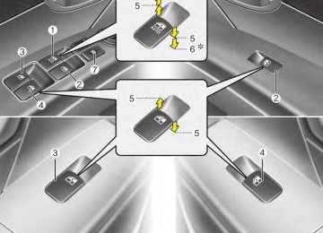
D080000AFD (1) Driver’s door power window switch (2) Front passenger’s door power win-
dow switch
(3) Rear door (left) power window switch (4) Rear door (right) power window
switch
(5) Window opening and closing (6) Automatic power window up*/down* (7) Power window lock switch
*: if equipped
✽✽ NOTICE In cold and wet climates, power win- dows may not work properly due to freezing conditions.
OCM040016
4 13
Features of your vehicle
Power windows The ignition switch must be in the ON position for power windows to operate. Each door has a power window switch that controls the door’s window. The dri- ver’s door has a master power window switch that controls all the windows in the vehicle The power windows can be operated for approximately 30 seconds after the igni- tion key is removed or turned to the ACC or LOCK position. However, if the front doors are opened, the power windows cannot be operated even within the 30
seconds period.✽✽ NOTICE While driving with the rear windows down or with the sunroof (if equipped) in an open (or partially open position), your vehicle may demonstrate a wind buffeting or pulsation noise. This noise is a normal occurrence and can be reduced or eliminated by taking the fol- lowing actions. If the noise occurs with one or both of the rear windows down, partially lower both front windows approximately one inch. If you experi- ence the noise with the sunroof open, slightly reduce the size of the sunroof opening.
14
OHM048016
OHM048015
D080101AUN Window opening and closing (if equipped) The driver’s door has a master power window switch that controls all the win- dows in the vehicle. To open or close a window, press down or pull up the front portion of the corre- sponding switch to the first detent posi- tion (5).
D080103AUN Auto up/down window (if equipped) Pressing or pulling up the power window switch momentarily to the second detent position (6) completely lowers or lifts the window even when is released. To stop the window at the desired position while the window is in operation, pull up or press down and release the switch. If the power window is not operated cor- rectly, the automatic power window sys- tem must be reset as follows: 1. Turn the ignition switch to the ON posi-
the switch
tion.
2. Close driver’s window and continue pulling up on driver’s power window switch for at least 1 second after the window is completely closed.
✽✽ NOTICE The automatic reverse feature for the driver’s window is only active when the “auto up” feature is used by fully pulling up the switch. The automatic reverse feature will not operate if the window is raised using the halfway posi- tion on the power window switch.
WARNING
Always check for obstructions before raising any window to avoid injuries or vehicle damage. If an object less than 0.16 in. (4 mm) in diameter is caught between the window glass and the upper win- dow channel, the automatic reverse window may not detect the resist- ance and will not stop and reverse direction.
Features of your vehicle
OCM052013
Power window lock button (cid:129) The driver can disable the power win- dow switches on a front and rear pas- senger door by pressing the power window lock button located on the dri- ver’s door to the LOCK position (pressed).
(cid:129) When the power window lock button is in the LOCK position (pressed), the driver’s master control cannot operate the front and rear passen- ger door power windows.
4 15
OUN026013
Automatic reversal If the upward movement of the window is blocked by an object or part of the body, the window will detect the resistance and will stop upward movement. The window will then lower approximately 11.8 in. (30
cm) to allow the object to be cleared. If the window detects the resistance while the power window switch is pulled up continuously, the window will stop upward movement then lower approxi- mately 1 in. (2.5 cm). And if the power window switch is pulled up continuously again within 5 seconds after the window is lowered by the automatic window reversal feature, the automatic window reversal will not operate.Features of your vehicle
CAUTION
(cid:129) To prevent possible damage to the power window system,do not open or close two windows or more at the same time.This will also ensure the longevity of the fuse.
(cid:129) Never try to operate the main switch on the driver's door and the individual door window switch in the opposite directions at the same time.If this is done, the window will stop and cannot be opened or closed.
WARNING - Windows
(cid:129) NEVER leave the ignition key in
the vehicle.
(cid:129) NEVER leave any child unattend- ed in the vehicle. Even very young children may inadvertently cause the vehicle to move, entan- gle themselves in the windows, or otherwise injure themselves or others.
(cid:129) Always double check to make sure all arms, hands, head and other obstructions are safely out of the way before closing a win- dow.
(cid:129) Do not allow children to play with the power windows. Keep the dri- ver’s door power window lock switch in the LOCK position (pressed). Serious injury can result from unintentional window operation by the child.
(cid:129) Do not extend face or arms out- side through the window opening while driving.
16
HOOD
Features of your vehicle
D090200AUN Closing the hood 1. Before closing the hood, check the fol-
lowing: (cid:129) All filler caps in engine compartment
must be correctly installed.
OCM040020
2. Go to the front of the vehicle, raise the hood slightly, push the secondary latch (1) inside of the hood center and lift the hood (2).3. Raise the hood. It will completely rise by itself after it has been raised about halfway.
OCM052018
D090100BUN Opening the hood 1. Pull the release lever to unlatch the hood. The hood should pop open slightly.
WARNING
Open the hood after turning off the engine on a flat surface, shifting the shift lever to the P(Park) posi- tion for automatic transaxle and to the 1st(First) gear or R(Reverse) for manual transaxle, and setting the parking brake.
(cid:129) Gloves, rags or any other com- bustible material must be removed from the engine compartment.
2. Lower the hood halfway and push
down to securely lock in place.
4 17
Features of your vehicle
WARNING - Hood
(cid:129) Before closing the hood, ensure that all obstructions are removed from the hood opening. Closing the hood with an obstruction present in the hood opening may result in property damage or severe personal injury.
(cid:129) Do not leave gloves, rags or any other combustible material in the engine compartment. Doing so may cause a heat-induced fire.
WARNING
(cid:129) Always double check to be sure that the hood is firmly latched before driving away. If it is not latched, the hood could fly open while the vehicle is being driven, causing a total loss of visibility, which might result in an accident. (cid:129) Do not move the vehicle with the hood raised. The view will be blocked and the hood could fall or be damaged.
18
FUEL FILLER LID
Features of your vehicle
D100200BUN Closing the fuel filler lid 1. To install the cap, turn it clockwise until it “clicks” one time. This indicates that the cap is securely tightened.
2. Close the fuel filler lid and push it light- ly and make sure that it is securely closed.
OHD046014
OCM041021
1. Stop the engine. 2. To open the fuel filler lid, pull the fuel
filler lid opener up.
3. Pull the fuel filler lid (1) out to fully
open.
4. To remove the cap (2), turn the fuel
tank cap counterclockwise.
5. Refuel as needed.
Opening the fuel filler lid The fuel-filler lid must be opened from inside the vehicle by pulling up on the fuel-filler lid opener located on the floor next to the driver’s seat.
✽✽ NOTICE If the fuel-filler lid will not open because ice has formed around it, tap lightly or push on the lid to break the ice and release the lid. Do not pry on the lid. If necessary, spray around the lid with an approved de-icer fluid (do not use radi- ator anti-freeze) or move the vehicle to a warm place and allow the ice to melt.
4 19
Features of your vehicle
D100300BFD
WARNING - Refueling
(cid:129) If pressurized fuel sprays out, it can cover your clothes or skin and thus subject you to the risk of fire and burns. Always remove the fuel cap carefully and slowly. If the cap is venting fuel or if you hear a hissing sound, wait until the condition stops before com- pletely removing the cap.
(cid:129) Do not "top off" after the nozzle automatically shuts off when refueling.
(cid:129) Tighten the cap until it “clicks” one time, otherwise the Check Engine
light will illuminate.
(cid:129) Always check that the fuel cap is installed securely to prevent fuel spillage in the event of an acci- dent.
20
WARNING - Refueling dan-
gers
Automotive fuels are flammable materials. When refueling, please note the following guidelines care- fully. Failure to follow these guide- lines may result in severe personal injury, severe burns or death by fire or explosion. (cid:129) Read and follow all warning at the
gas station facility.
(cid:129) Before refueling note the location of the Emergency Gasoline Shut- Off, if available, at the gas station facility.
(cid:129) Before touching the fuel nozzle, you should eliminate potentially dangerous static electricity dis- charge by touching another metal part of the vehicle, a safe dis- tance away from the fuel filler neck, nozzle, or other gas source. (Continued)
(Continued) (cid:129) Do not get back into a vehicle once you have begun refueling since you can generate static electricity by touching, rubbing or sliding against any item or fab- ric (polyester, satin, nylon, etc.) capable of producing static elec- tricity. Static electricity discharge can ignite fuel vapors resulting in rapid burning. If you must re- enter the vehicle, you should once again eliminate potentially dangerous static electricity dis- charge by touching a metal part of the vehicle, away from the fuel filler neck, nozzle or other gaso- line source.
(cid:129) When using a portable fuel con- tainer be sure to place the con- tainer on the ground prior to refu- eling. Static electricity discharge from the container can ignite fuel vapors causing a fire. Once refu- eling has begun, contact with the vehicle should be maintained until the filling is complete.
(Continued)
(Continued) (cid:129) If a fire breaks out during refuel- ing, leave the vicinity of the vehi- cle, and immediately contact the manager of the gas station and then contact the local fire depart- ment or 911. Follow any safety instructions they provide.
(Continued)
Use only portable plastic fuel containers designed to carry and store gasoline.
(cid:129) Do not use cellular phones while refueling. Electric current and/or electronic interference from cel- lular phones can potentially ignite fuel vapors causing a fire. (cid:129) When refueling, always shut the engine off. Sparks produced by electrical components related to the engine can ignite fuel vapors causing a fire. Once refueling is complete, check to make sure the filler cap and filler door are securely closed, before starting the engine.
(cid:129) DO NOT use matches or a lighter and DO NOT SMOKE or leave a lit cigarette in your vehicle while at a gas station especially during refueling. Automotive fuel is highly flammable and can, when ignited, result in fire.
(Continued)
Features of your vehicle
CAUTION
(cid:129) Make sure to refuel your vehicle according to the "Fuel require- ments" suggested in section 1.
(cid:129) If the fuel filler cap requires replacement, use only a genuine HYUNDAI cap or the equivalent specified for your vehicle. An incorrect fuel filler cap can result in a serious malfunction of the fuel system or emission control system.
(cid:129) Do not spill fuel on the exterior surfaces of the vehicle.Any type of fuel spilled on painted surfaces may damage the paint.
(cid:129) After refueling,make sure the fuel cap is installed securely to pre- vent fuel spillage in the event of an accident.
4 21
Features of your vehicle
SUNROOF (IF EQUIPPED)
OCM040232N
D110000AUN If your vehicle is equipped with this fea- ture, you can slide or tilt your sunroof with the sunroof control switch located on the overhead console.
The sunroof can only be opened, closed, or tilted when the ignition switch is in the ON position.
22
✽✽ NOTICE • In cold and wet climates, sunroof may not work properly due to freezing conditions.
• After washing the car or after there is rain, be sure to wipe off any water that is on the sunroof before operating it.
CAUTION
Do not continue to press the sun- roof control switch after the sunroof is fully opened, closed, or tilted. Damage to the motor or system components could occur.
✽✽ NOTICE The sunroof cannot slide when it is in the tilt position nor can it be tilted while in an open or slide position.
WARNING
Never adjust the sunroof or sun- shade while driving. This could result in loss of control and an acci- dent that may cause death, serious injury, or property damage.
OCM029024L
D110100AFD Sliding the sunroof To open the sunroof (autoslide feature), move the sunroof control switch towards the rear of the vehicle for more than 0.5
second. The sunroof will slide to the recommend- ed open position. To stop the sunroof sliding at any point, pull or push the sunroof control switch momentarily.✽✽ NOTICE To reduce wind noise while driving, we recommend you to drive at the recom- mended position.
To close the sunroof (autoslide feature), move the sunroof control switch towards the front of the vehicle for more than 0.5
second. The sunroof will close all the way. To stop the sunroof sliding at any point, pull or push the sunroof control switch momen- tarily.Features of your vehicle
OUN026027
OCM029025L
D110101AUN Automatic reversal If an object or part of the body is detect- ed while the sunroof is closing automati- cally, it will reverse the direction, and then stop. The auto reverse function does not work if a tiny obstacle is between the sliding glass and the sunroof sash. You should always check that all passengers and objects are away from the sunroof before closing it.
D110200AUN Tilting the sunroof To open the sunroof (autotilt feature), push the sunfoof control switch upward for more than 0.5 second. The sunroof will tilt all the way open. To stop the sunroof tilting at any point, pull the sunfoof control switch downward momentarily. To close the sunroof, pull the sunroof control switch downward and hold it until the sunroof is closed.
4 23
Features of your vehicle
WARNING - Sunroof
(cid:129) Be careful that someone’s head, hands and body are not trapped by a closing sunroof.
(cid:129) Do not extend face, neck, arms or body outside through the sunroof opening while driving.
(cid:129) Make sure hand and face are safely out of the way before clos- ing a sunroof.
CAUTION
(cid:129) Periodically remove any dirt that may accumulate on the guide rail. (cid:129) If you try to open the sunroof when the temperature is below freezing or when the sunroof is covered with snow or ice, the glass or the motor could be dam- aged.
(cid:129) While using sunroof for a long time,a dust between sunroof and roof panel can make a noise. Open the sunroof and remove regularly the dust using clean cloth.
(cid:129) The sunroof is made to slide together with sunshade. Do not leave the sunshade closed while the sunroof is open.
OHM048028
D110300AUN Sunshade The sunshade will be opened with the glass panel automatically when the glass panel is slid.You will have to close it man- ually if you want it closed.
24
Features of your vehicle
❈ For more detailed information, contact
an authorized HYUNDAI dealer.
CAUTION
If the sunroof is not reset when the vehicle battery is disconnected or discharged, or related fuse is blown, the sunroof may operate improperly.
Resetting the sunroof Whenever the vehicle battery is discon- nected or discharged, or related fuse is blown, you must reset your sunroof sys- tem as follows:
1. Turn the ignition switch to the ON position and close the sunroof com- pletely.
2. Release the control switch. 3. Pull and hold the sunroof control switch downward until the sunroof tilts and slightly moves up and down. Then, release the control switch.
4. Pull and hold the sunroof control switch downward until the sunroof is operated as follows;
TILT DOWN → SLIDE OPEN → SLIDE CLOSE
Then, release the control switch.
When this is complete, the sunroof sys- tem is reset.
4 25
Features of your vehicle
STEERING WHEEL Power steering Power steering uses energy from the engine to assist you in steering the vehi- cle. If the engine is off or if the power steering system becomes inoperative, the vehicle may still be steered, but it will require increased steering effort. Should you notice any change in the effort required to steer during normal vehicle operation, have the power steer- ing checked by an authorized HYUNDAI dealer.
CAUTION
Never hold the steering wheel to the extreme right or left for more than 5
seconds with the engine running. Holding the steering wheel for more than 5 seconds in either position may cause damage to the power steering pump.✽✽ NOTICE If the power steering drive belt breaks or if the power steering pump malfunc- tions, the steering effort will greatly increase.
✽✽ NOTICE If the vehicle is parked for extended periods outside in cold weather (below 14°F/-10°C), the power steering may require increased effort when the engine is first started. This is caused by increased fluid viscosity due to the cold weather and does not indicate a mal- function. When this happens, increase the engine RPM by depressing the accelerator until the RPM reaches 1,500 rpm then release or let the engine idle for two or three minutes to warm up the fluid.
D130300AFD Tilt steering A tilt steering wheel allows you to adjust the steering wheel before you drive. You can also raise it to give your legs more room when you exit and enter the vehicle (if equipped).
The steering wheel should be positioned so that it is comfortable for you to drive, while permitting you to see the instru- ment panel warning lights and gauges.
WARNING
(cid:129) Never adjust the angle and height of steering wheel while driving. You may lose your steering con- trol and cause severe personal injury or accidents.
(cid:129) After adjusting, push the steering wheel both up and down to be certain it is locked in position.
26
Type A
Features of your vehicle
CAUTION
Do not strike the horn severely to operate it,or hit it with your fist.Do not press on the horn with a sharp- pointed object.
Type B
OCM040180
OCM040033
To change the steering wheel angle, pull down the lock release lever (1), adjust the steering wheel to the desired angle (2) and height (if equipped) (3), then pull up the lock-release lever to lock the steering wheel in place. Be sure to adjust the steering wheel to the desired position before driving.OCM040034
D130500AUN Horn To sound the horn, press the horn sym- bol on your steering wheel. Check the horn regularly to be sure it operates properly.
✽✽ NOTICE To sound the horn, press the area indi- cated by the horn symbol on your steer- ing wheel (see illustration). The horn will operate only when this area is pressed.
4 27
Features of your vehicle
MIRRORS Inside rearview mirror Adjust the rearview mirror so that the center view through the rear window is seen. Make this adjustment before you start driving.
WARNING - Rear visibility Do not place objects in the rear seat or cargo area which would interfere with your vision out the rear window.
WARNING
Do not modify the inside mirror and do not install a wide mirror. It could result in injury, during an accident or deployment of the air bag.
28
Night
Day
OAM049023
D140101AUN Day/night rearview mirror Make this adjustment before you start driving and while the day/night lever is in the day position. Pull the day/night lever toward you to reduce glare from the headlights of vehi- cles behind you during night driving. Remember that you lose some rearview clarity in the night position.
B520C08JM
Electric chromic mirror (ECM) with compass (if equipped) (1) Status Indicator LED (2) Feature Control Button (3) Rear Light Sensor (4) Display Window
The electric chromic mirror automatically controls the glare from headlights behind you when the function is turned on by pressing and holding the Feature Control Button for more than 3 but less than 6
seconds. This feature can be turned off by pressing and holding the button for the same amount of time once more.To operate Compass feature Press and release the button, then the vehicle's directional heading will be dis- played. Pressing and releasing the button again will turn off the display.
Heading display
- E : East - W : West - S : South - N : North
ex) NE : North East
Calibration procedure The compass may not indicate the cor- rect compass direction if the electronic compass has not been calibrated cor- rectly, if the compass zone number is dif- ferent from your current location, or when you are driving in certain areas (tunnel, parking garage, underground parking lot, near transformer substation, etc.), and the following may occur:
- “C” is displayed. - The compass headings become inac-
curate.
- The compass heading does not change when the vehicle changes direction.
- Some compass headings are not dis-
played.
- The compass headings are inaccurate
in long distance driving.
Features of your vehicle
If the vehicle’s compass headings become inaccurate, the compass should be calibrated as follows: 1.Ensure the vehicle is not located near large steel structures or under electric power lines.
2.Turn on the compass by pressing the
button.
3.Press and hold the button for more than 6 but less than 9 seconds. The current zone number will appear in the display. Release then press the button until your zone number appears in the display.
4.Check the mirror angle by pressing and holding the button for more than 12seconds. Release then press the button to “L”(for steering wheel on the Left side of the vehicle). (if installed)
5.Press and hold the button between 9
and 12 seconds. Release the button when a “C” appears in the display.6.Drive the vehicle in 2 complete circles at less than 5mph(8km/h) or until the compass heading appears.
CAUTION
Be sure the area is free of traffic, pedestrians,and obstructions.
4 29
Features of your vehicle
Setting the compass zone 1.Determine the Zone Number based on your current location in the Zone Map. 2.Press and hold the button for more than 6 but less than 9 seconds. The current zone number will appear in the display.
3.Release then press the button to incre-
ment to new your zone number.
4.Drive the vehicle in 2 complete circles at less than 5mph(8km/h) or until the compass heading appears.
B520C05NF
30
D140105AEN Electric chromic mirror (ECM) with compass and HomeLink® system (if equipped) Your vehicle may be equipped with a Gentex Automatic-Dimming Mirror with a Z-Nav™ Electronic Compass Display and an Integrated HomeLink® Wireless Control System. During nighttime driving, this feature will automatically detect and reduce rearview mirror glare while the compass indicates the direction the vehi- cle is pointed. The HomeLink® Universal Transceiver allows you to activate your garage door(s), electric gate, home light- ing, etc.
CAUTION
(cid:129) Do not install a ski rack,antenna, etc.that is attached to the vehicle using a magnet. Anything attached to the roof of the vehicle with a magnet will effect the com- pass operation.
(cid:129) If the compass deviates from the correct indication after repeating the adjustment, have the com- pass checked by an authorized dealer.
(cid:129) The compass may not indicate the correct compass point in tun- nels or while driving up or down a steep hill. (The compass returns to the correct compass point when the vehicle moves to an area where the geomagnetism is stabilized.)
(cid:129) When cleaning the mirror, use a paper towel or similar material dampened with glass cleaner.Do not spray glass cleaner directly on the mirror as that may cause the liquid cleaner to enter the mir- ror housing.
Features of your vehicle
OEN046033N
(1) Channel 1 button (2) Channel 2 button (3) Status indicator LED (4) Channel 3 button (5) Rear light sensor (6) Dimming ON/OFF button (7) Compass control button (8) Compass display
4 31
Features of your vehicle
Automatic-Dimming Night Vision Safety™ (NVS®) Mirror The NVS® Mirror in your vehicle is the most advanced way to reduce annoying glare in the rearview mirror during any driving situation. For more information regarding NVS® mirrors and other appli- cations, please refer to the Gentex web- site: www.gentex.com
CAUTION
The NVS® Mirror automatically reduces glare during driving condi- tions based upon light levels moni- tored in front of the vehicle and from the rear of the vehicle.These light sensors are visible through openings in the front and rear of the mirror case.Any object that would obstructs either light sensor will degrade the automatic dimming control feature.
32
Automatic-dimming function Your mirror will automatically dim upon detecting glare from the vehicles travel- ing behind you. The auto-dimming func- tion can be controlled by the Dimming ON/OFF Button:
Z-Nav™ Compass Display The NVS™ Mirror in your vehicle is also equipped with a Z-Nav™ Compass that shows the vehicle Compass heading in the Display Window using the 8 basic cardinal headings (N, NE, E, SE, etc.).
1. Pressing the
button turns the auto- dimming function OFF which is indicat- ed by the green Status Indicator LED turning off.
2. Pressing the
button again turns the auto-dimming function ON which is indicated by the green Status Indicator LED turning on.
✽✽ NOTICE The mirror defaults to the ON position each time the vehicle is started.
Compass function The Compass can be turned ON and OFF and will remember the last state when the ignition is cycled. To turn the display feature ON/OFF: 1. Press and release the
button to
turn the display feature OFF.
2. Press and release the
button again
to turn the display back ON.
Additional options can be set with press and hold sequences of the button and are detailed below.
There is a difference between magnetic north and true north. The compass in the mirror can compensate for this difference when it knows the Magnetic Zone in which it is operating. This is set either by the dealer or by the user. The operating Zone Numbers for North America are shown in the figure on the following sec- tion.
Features of your vehicle
To adjust the Zone setting: 1. Determine the desired Zone Number based upon your current location on the Zone Map.
2. Press and hold the
button for more than 3 but less than 6 seconds, the current Zone Number will appear on the display.
3. Pressing and holding the
button again will cause the numbers to incre- ment (Note: they will repeat …13, 14, 15, 1, 2, …). Releasing the button when the desired Zone Number appears on the display will set the new Zone.
4. Within about 5 seconds the compass will start displaying a compass head- ing again.
There are some conditions that can cause changes to the vehicle magnets, such as installing a ski rack or a CB antenna. Body repair work on the vehicle can also cause changes to the vehicle's magnetic field. In these situations, the compass will need to be re-calibrated to quickly correct for these changes. To re- calibrate the compass:
B520C05NF
4 33
Features of your vehicle
1. Press and hold the
button for more than 6 seconds. When the compass memory is cleared a "C" will appear in the display.
2. To calibrate the compass, drive the vehicle in 2 complete circles at less than 5 mph (8 km/h).
Integrated HomeLink® Wireless Control System The HomeLink® Wireless Control System provides a convenient way to replace up to three hand-held radio-fre- quency (RF) transmitters with a single built-in device. This innovative feature will learn the radio frequency codes of most current transmitters to operate devices such as gate operators, garage door openers, entry door locks, security sys- tems, even home lighting. Both standard and rolling code-equipped transmitters can be programmed by following the out- lined procedures. Additional HomeLink® information can be found at: www.home- link.com or by calling 1-800-355-3515.
34
Programming HomeLink® ✽✽ NOTICE • When programming a garage door opener, it is advised to park the vehi- cle outside of the garage.
• It is recommended that a new battery be placed in the hand-held transmit- ter of the device being programmed to HomeLink® for quicker training and accurate transmission of the radio- frequency signal.
• Some vehicles may require the igni- tion switch to be turned to the second (or "accessories") position for pro- gramming and/or operation of HomeLink.
• In the event that there are still pro- gramming difficulties or questions after following the programming steps listed below, contact HomeLink® at: www.homelink.com or 1-800-355- 3515.
CAUTION
Before programming HomeLink® to a garage door opener or gate oper- ator, make sure that people and objects are out of the way of the device to prevent potential harm or damage. Do not use HomeLink® with any garage door opener that lacks the safety stop and reverse features required by U.S. federal safety standards (this includes any garage door opener model manu- factured before April 1, 1982). A garage door that cannot detect an object - signaling the door to stop and reverse - does not meet current U.S.federal safety standards.Using a garage door opener without these features increases the risk of seri- ous injury or death.
Retain the original transmitter of the RF device you are programming for use in other vehicles as well as for future HomeLink® programming. It is also sug- gested that upon the sale of the vehicle, the programmed HomeLink® buttons be erased for security purposes.
Standard programming To train most devices, follow these instructions: 1. For first-time programming, press and hold two outside buttons, HomeLink® Channel 1 and Channel 3
Buttons, until the indicator light begins to flash (after 20 seconds). Release both buttons. Do not hold the buttons for longer than 30 seconds.the
2. Position the end of your hand-held transmitter 1-3 inches (2-8 cm) away from the HomeLink® buttons while keeping the indicator light in view.
3. Simultaneously press and hold both the HomeLink® and hand-held trans- mitter button. DO NOT release the but- tons until step 4 has been completed. 4. While continuing to hold the buttons the red Indicator Status LED will flash slowly and rapidly after HomeLink® successfully trains to the frequency signal from the hand-held transmitter. Release both buttons.
then
the
5. Press and hold
just-trained HomeLink® button and observe the red Status Indicator LED. If the indicator light stays on constantly, programming is complete and your device should activate when the HomeLink® button is pressed and released.
6. To program
two HomeLink® buttons, follow steps 2
through 5.remaining
the
Rolling code programming Rolling code devices which are "code- protected" and manufactured after 1996
may be determined by the following: (cid:129) Reference the device owner's manualfor verification.
(cid:129) The handheld transmitter appears to program the HomeLink® Universal Transceiver but does not activate the device.
(cid:129) Press and hold the trained HomeLink button. The device has the rolling code feature if the indicator light flashes rap- idly and then turns solid after 2 sec- onds.
Features of your vehicle
To train rolling code devices, follow these instructions: 1. At the garage door opener receiver (motor-head unit) in the garage, locate the "learn" or "smart" button. This can usually be found where the hanging antenna wire is attached to the motor- head unit. Exact location and color of the button may vary by garage door opener brand. If there is difficulty locating the training button, reference the device owner's manual or please visit our Web site at www.homelink.com.
2. Firmly press and release the "learn" or "smart" button (which activates the "training light").
4 35
Features of your vehicle
✽✽ NOTICE There are 30 seconds in which to initiate step3.
3. Return to the vehicle and firmly press, hold for two seconds and then release the desired HomeLink® button. Repeat the "press/hold/release" sequence a second time to complete the program- ming. (Some devices may require you to repeat this sequence a third time to complete the programming.)
the
4. Press and hold
just-trained HomeLink® button and observe the red Status Indicator LED. If the indicator light stays on constantly, programming is complete and your device should activate.
5. To program
the
remaining
two HomeLink® buttons, follow either steps 1 through 4 above for other Rolling Code devices or steps 2 through 5 in Standard Programming for standard devices.
Gate operator & Canadian program- ming During programming, your handheld transmitter may automatically stop trans- mitting. Continue to press the Integrated HomeLink® Wireless Control System but- ton (note steps 2 through 4 in the Standard Programming portion of this document) while you press and re-press ("cycle") your handheld transmitter every two seconds until the frequency signal has been learned. The indicator light will flash slowly and then rapidly after sever- al seconds upon successful training.
HomeLink®
Operating HomeLink® To operate, simply press and release the button. programmed Activation will now occur for the trained device (i.e. garage door opener, gate operator, security system, entry door lock, home/office lighting, etc.). For con- venience, the hand-held transmitter of the device may also be used at any time.
Reprogramming a single HomeLink® button To program a new device to a previously trained HomeLink® button, follow these steps: 1. Press and hold the desired HomeLink® button. Do NOT release until step 4
has been completed.2. When the indicator light begins to flash slowly (after 20 seconds), position the handheld transmitter 1 to 3 inches away from the HomeLink® surface.
3. Press and hold the handheld transmit- ter button. The HomeLink® indicator light will flash, first slowly and then rap- idly.
4. When the indicator light begins to flash
rapidly, release both buttons.
the
5. Press and hold
just-trained HomeLink® button and observe the red Status Indicator LED. If the indicator light stays on constantly, programming is complete and your new device should activate.
36
Erasing HomeLink® buttons Individual buttons cannot be erased. However, to erase all three programmed buttons: 1. Press and hold
two outer HomeLink® buttons until the indicator light begins to flash-after 20 seconds. 2. Release both buttons. Do not hold for
the
longer than 30 seconds.
The Integrated HomeLink® Wireless Control System is now in the training (learn) mode and can be programmed at any time following the appropriate steps in the Programming sections above.
Features of your vehicle
NVS® is a registered trademark and Z- Nav™ is a trademark of the Gentex Corporation, Zeeland, Michigan. HomeLink® is a registered trademark owned Controls, Incorporated, Milwaukee, Wisconsin.
Johnson
by
FCC ID: NZLZTVHL3
IC: 4112A-ZTVHL3This device complies with Part 15 of the FCC Rules. Operation is subject to the following two conditions: 1. this device may not cause harmful
interference, and
2. This device must accept any interfer- ence received, including interference that may cause undesired operation.
WARNING
The transceiver has been tested and complies with FCC and Industry Canada rules. Changes or modifications expressly approved by the party responsible for compliance could void the user's authority to operate the device.
not
4 37
Features of your vehicle
D140200AUN Outside rearview mirror Be sure to adjust mirror angles before driving. Your vehicle is equipped with both left- hand and right-hand outside rearview mirrors. The mirrors can be adjusted remotely with the remote switch. The mir- ror heads can be folded back to prevent damage during an automatic car wash or when passing in a narrow street.
WARNING - Rearview mir-
rors
(cid:129) The right outside rearview mirror is convex. Objects seen in the mirror are closer they appear.
than
(cid:129) Use your interior rearview mirror or direct observation to deter- mine the actual distance of fol- lowing vehicles when changing lanes.
38
CAUTION
Do not scrape ice off the mirror face;this may damage the surface of the glass. If ice should restrict movement of the mirror, do not force the mirror for adjustment.To remove ice,use a deicer spray,or a sponge or soft cloth with very warm water.
CAUTION
If the mirror is jammed with ice,do not adjust the mirror by force.Use an approved spray de-icer (not radi- ator antifreeze) to release the frozen mechanism or move the vehicle to a warm place and allow the ice to melt.
WARNING
Do not adjust or fold the outside rearview mirrors while the vehicle is moving. This could result in loss of control, and an accident which could cause death, serious injury or property damage.
OCM040038
Remote control The electric remote control mirror switch allows you to adjust the position of the left and right outside rearview mirrors. To adjust the position of either mirror, move the lever (1) to R or L to select the right side mirror or the left side mirror, then press a corresponding point on the mirror adjustment control to position the select- ed mirror up, down, left or right. After adjustment, put the lever into neu- tral position inadvertent adjustment.
to prevent
CAUTION
(cid:129) The mirrors stop moving when they reach the maximum adjust- ing angles,but the motor contin- ues to operate while the switch is pressed.Do not press the switch longer than necessary,the motor may be damaged.
(cid:129) Do not attempt to adjust the out- side rearview mirror by hand. Doing so may damage the parts.
B510E01E
D140202AFD Folding the outside rearview mirror To fold outside rearview mirror, grasp the housing of mirror and then fold it toward the rear of the vehicle.
Features of your vehicle
4 39
Features of your vehicle
INSTRUMENT CLUSTER
1. Tachometer 2. Engine coolant temperature gauge 3. Fuel gauge 4. Speedometer
5. Turn signal indicators 6. Warning and indicator lights 7. Odometer/Trip computer (if equipped)
* The actual cluster in the vehicle may differ from the illustration. For more details refer to "Gauges" in the next pages.
40
OCM042050N
Features of your vehicle
OCM052056
OCM040053N
OCM040053N
Instrument panel illumination When the vehicle’s parking lights or head- lights are on, rotate the illumination con- trol knob to adjust the instrument panel illumination intensity.
Gauges D150201AUN Speedometer The speedometer indicates the forward speed of the vehicle. The speedometer is calibrated in miles per hour and/or kilometers per hour.
D150202AFD Tachometer The tachometer indicates the approxi- mate number of engine revolutions per minute (rpm). Use the tachometer to select the correct shift points and to prevent lugging and/or over-revving the engine.
The tachometer pointer may move slight- ly when the ignition switch is in ACC or ON position with the engine OFF. This movement is normal and will not affect the accuracy of the tachometer once the engine is running.
4 41
Features of your vehicle
CAUTION
Do not operate the engine within the tachometer's RED ZONE. This may cause severe engine damage.
WARNING
Never remove the radiator cap when the engine is hot. The engine coolant is under pressure and could cause severe burns. Wait until the engine is cool before adding coolant to the reservoir.
OCM040057
D150203AUN Engine coolant temperature gauge This gauge shows the temperature of the engine coolant when the ignition switch is ON. Do not continue driving with an overheat- ed engine. If your vehicle overheats, refer to “If the engine overheats” in section 6.
CAUTION
If the gauge pointer moves beyond the normal range area toward the “H”position, it indicates overheat- ing that may damage the engine.
42
WARNING - Fuel gauge
Running out of fuel can expose vehicle occupants to danger. You must stop and obtain addition- al fuel as soon as possible after the warning light comes on or when the gauge indicator comes close to the E level.
CAUTION
Avoid driving with a very low fuel level.If you run out of fuel,it could cause the engine to misfire and result in excessive loading of the catalytic converter.
OCM040058
D150204AUN Fuel gauge The fuel gauge indicates the approxi- mate amount of fuel remaining in the fuel tank. The fuel tank capacity is given in section 8. The fuel gauge is supplement- ed by a low fuel warning light, which will illuminate when the fuel tank is nearly empty. On inclines or curves, the fuel gauge pointer may fluctuate or the low fuel warning light may come on earlier than usual due to the movement of fuel in the tank.
Features of your vehicle
OCM040071R
D150205AFD Odometer/Tripmeter (if equipped) Push the TRIP button for less than 1 sec- ond to select odmeter, tripmeter A or B or ECO ON/OFF as follows:
TRIP A → TRIP B → Odometer→ ECO ON/OFF* →
* if equipped
4 43
Features of your vehicle
Odometer The odometer indicates the total dis- tance the vehicle has been driven. You will also find the odometer useful to determine when periodic maintenance should be performed.
✽✽ NOTICE It is forbidden to alter of the odometer of any vehicle with the intent to change the mileage registered on the odometer. The alteration may void your warranty coverage.
44
OCM040060
OHD040550
Tripmeter The tripmeter indicates the distance of individual trip selected by the driver. Tripmeter can be reset to 0 by pressing the RESET button for 1 second or more.
ECO ON/OFF mode (if equipped) You can turn the ECO indicator on/off on the instrument cluster in this mode. If you push the RESET button more than 1 second in the ECO ON mode, ECO OFF is displayed in the screen and the ECO indicator turns off while driving. If you want to display the ECO indicator again, press the RESET button more than 1 second in the ECO OFF mode and then ECO ON mode is displayed in the screen. When you press the TRIP button less than 1 second in the ECO mode, the mode is changed to tripmeter.
Tripmeter A
Tripmeter B*
Distance to empty*
Average fuel consumption*
Average speed*
Outside air temperature*
ECO ON/OFF*
* if equipped
Features of your vehicle
OCM040061N
Odometer The odometer indicates the total dis- tance the vehicle has been driven. You will also find the odometer useful to determine when periodic maintenance should be performed.
OCM040060
D150206AFD Trip computer (if equipped) The trip computer is a microcomputer- controlled driver information system that displays information related to driving on the display when the ignition switch is in the ON position. All stored driving infor- mation (except odometer, distance to empty and instant fuel consumption) is resets if the battery is disconnected.
4 45
Features of your vehicle
OCM040062N
OCM040063N
OCM040065N
Tripmeter TRIP A : Tripmeter A TRIP B : Tripmeter B This mode indicates the distance of indi- vidual trips selected since the last trip- meter reset. The meter's working range is from 0.0 to 999.9 miles (0.0 to 999.9 km). Pressing the RESET button for more than 1 second, when the tripmeter (TRIP A or TRIP B) is being displayed, clears the tripmeter to zero (0.0).
Distance to empty (if equipped) This mode indicates the estimated dis- tance to empty based on the current fuel in the fuel tank and the amount of fuel delivered to the engine. When the remaining distance is below 30 miles (50
km), “---” will be displayed and the dis- tance to empty indicator will blink. The meter’s working range is from 30 to 999 miles (50 to 999 km).Average fuel consumption (if equipped) This mode calculates the average fuel consumption from the total fuel used and the distance since the last average con- sumption reset. The total fuel used is cal- culated from the fuel consumption input. For an accurate calculation, drive more than 0.03 miles (50 m). Pressing the RESET button for more than 1 second, when the average fuel con- sumption is being displayed, clears the average fuel consumption to zero (--.-).
46
✽✽ NOTICE • If the vehicle is not on level ground or the battery power has been interrupt-