- 2008 Ford F 250 Owners Manuals
- Ford F 250 Owners Manuals
- 2012 Ford F 250 Owners Manuals
- Ford F 250 Owners Manuals
- 2000 Ford F 250 Owners Manuals
- Ford F 250 Owners Manuals
- 2001 Ford F 250 Owners Manuals
- Ford F 250 Owners Manuals
- 2006 Ford F 250 Owners Manuals
- Ford F 250 Owners Manuals
- 2015 Ford F 250 Owners Manuals
- Ford F 250 Owners Manuals
- 2010 Ford F 250 Owners Manuals
- Ford F 250 Owners Manuals
- 2004 Ford F 250 Owners Manuals
- Ford F 250 Owners Manuals
- 1999 Ford F 250 Owners Manuals
- Ford F 250 Owners Manuals
- 2007 Ford F 250 Owners Manuals
- Ford F 250 Owners Manuals
- 2009 Ford F 250 Owners Manuals
- Ford F 250 Owners Manuals
- 2013 Ford F 250 Owners Manuals
- Ford F 250 Owners Manuals
- 2016 Ford F 250 Owners Manuals
- Ford F 250 Owners Manuals
- 1998 Ford F 250 Owners Manuals
- Ford F 250 Owners Manuals
- 2005 Ford F 250 Owners Manuals
- Ford F 250 Owners Manuals
- 2011 Ford F 250 Owners Manuals
- Ford F 250 Owners Manuals
- 2014 Ford F 250 Owners Manuals
- Ford F 250 Owners Manuals
- 2002 Ford F 250 Owners Manuals
- Ford F 250 Owners Manuals
- 2003 Ford F 250 Owners Manuals
- Ford F 250 Owners Manuals
- 1996 Ford F 250 Owners Manuals
- Ford F 250 Owners Manuals
- Download PDF Manual
-
POWER STEERING FLUID Check the power steering fluid. Refer to the scheduled maintenance information for the service interval schedules. If adding fluid is necessary, use only MERCON威 ATF. • Gasoline engine shown; diesel engine similar. Refer to Identifying components in the engine compartment in the 6.0
and 6.4 Liter Power Stroke Direct Injection Turbo Diesel Owner Guide Supplement.Check the fluid level when it is at ambient temperature, 20°F–80°F (-7°C–25°C): 1. Check the fluid level in the reservoir. It should be between the MIN and MAX range. Do not add fluid if the level is within this range. 2. If the fluid level is low. Add fluid to bring fluid level up to be between the MIN and MAX range. 3. Start the engine. 4. While the engine idles, turn the steering wheel left and right several times. 5. Turn the engine off. 6. Recheck the fluid level in the reservoir. Do not add fluid if the level is between the MIN and MAX range. 7. If the fluid is low, add fluid in small amounts, continuously checking the level until it is between the MIN and MAX range. Be sure to put the cap back on the reservoir.
373
2008 F-250/350/450/550 (f23) Owners Guide (post-2002-fmt) USA (fus)
Maintenance and Specifications
BRAKE FLUID • Vacuum boost system
• Hydroboost system
• FEAD-driven vacuum pump/brake
booster system
374
2008 F-250/350/450/550 (f23) Owners Guide (post-2002-fmt) USA (fus)
Maintenance and Specifications
The fluid level will drop slowly as the brakes wear, and will rise when the brake components are replaced. Fluid levels between the “MIN” and “MAX” lines are within the normal operating range; there is no need to add fluid. If the fluid levels are outside of the normal operating range the performance of your brake system could be compromised; seek service from your authorized dealer immediately.
CLUTCH FLUID (IF EQUIPPED) Check the clutch fluid level. Refer to the scheduled maintenance information for the service interval schedules. Use only a DOT 3 brake fluid designed to meet Ford specifications. Refer to Maintenance product specifications and capacities in this chapter.
Carefully read cautionary information on product label. For MEDICAL EMERGENCY INFORMATION, contact a physician or Poison Control Center immediately; on Ford-Motorcraft products call: 1-800-959-3673 (FORD). Failure to follow these instructions may result in personal injury.
During normal operation, the fluid level in the clutch reservoir should remain constant or rise slightly. If the fluid level drops, refill the fluid level to the step in the reservoir. 1. Clean the reservoir cap before removal to prevent dirt and water from entering the reservoir. 2. Remove cap and rubber diaphragm from reservoir. 3. Add fluid until the level reaches the step in the reservoir. 4. Reinstall rubber diaphragm and cap onto reservoir.
TRANSMISSION FLUID
Checking automatic transmission fluid (if equipped) Refer to your scheduled maintenance information for scheduled intervals for fluid checks and changes. Your transmission does not consume fluid. However, the fluid level should be checked if the transmission is not working properly, i.e., if the transmission slips or shifts slowly or if you notice some sign of fluid leakage.
375
2008 F-250/350/450/550 (f23) Owners Guide (post-2002-fmt) USA (fus)
Maintenance and Specifications
Automatic transmission fluid expands when warmed. To obtain an accurate fluid check, drive the vehicle until it is at normal operating temperature (approximately 20 miles [30 km]). If your vehicle has been operated for an extended period at high speeds, in city traffic during hot weather or pulling a trailer, the vehicle should be turned off for about 30
minutes to allow fluid to cool before checking. 1. Drive the vehicle 20 miles (30 km) or until it reaches normal operating temperature. 2. Park the vehicle on a level surface and engage the parking brake. 3. With the parking brake engaged and your foot on the brake pedal, start the engine and move the gearshift lever through all of the gear ranges. Allow sufficient time for each gear to engage. 4. Latch the gearshift lever in P (Park) and leave the engine running. 5. Remove the dipstick, wiping it clean with a clean, dry lint free rag. If necessary, refer to Identifying components in the engine compartment in this chapter for the location of the dipstick. 6. Install the dipstick making sure it is fully seated in the filler tube. 7. Remove the dipstick and inspect the fluid level. The fluid should be in the designated area for normal operating temperature or ambient temperature.Low fluid level Do not drive the vehicle if the fluid level is at the bottom of the dipstick and the ambient temperature is above 50°F (10°C).
Correct fluid level The transmission fluid should be checked at normal operating temperature 150°F-170°F (66°C-77°C) on a level surface. The normal operating temperature can be reached after approximately 20 miles (30
km) of driving. You can check the fluid without driving if the ambient temperature is above 50°F (10°C). However, if fluid is added at this time, an overfill condition could result when the vehicle reaches normal operating temperature.376
2008 F-250/350/450/550 (f23) Owners Guide (post-2002-fmt) USA (fus)
Maintenance and Specifications
The transmission fluid should be in this range if at normal operating temperature (150°F-170°F [66°C-77°C]). The transmission fluid should be in this range if at ambient temperature (50°F-95°F [10°C-35°C]).
High fluid level Fluid levels above the safe range may result in transmission failure. An overfill condition of transmission fluid may cause shift and/or engagement concerns and/or possible damage. High fluid levels can be caused by an overheating condition. Adjusting automatic transmission fluid levels Before adding any fluid, make sure the correct type is used. The type of fluid used is normally indicated on the dipstick handle and also in the Maintenance Product Specifications and Capacities section in this chapter. Use of a non-approved automatic transmission fluid may cause internal transmission component damage. If necessary, add fluid in 1/2 pint (250 ml) increments through the filler tube until the level is correct. If an overfill occurs, excess fluid should be removed by a qualified technician. An overfill condition of transmission fluid may cause shift and/or engagement concerns and/or possible damage. Do not use supplemental transmission fluid additives, treatments or cleaning agents. The use of these materials may affect transmission operation and result in damage to internal transmission components.
377
2008 F-250/350/450/550 (f23) Owners Guide (post-2002-fmt) USA (fus)
Maintenance and Specifications
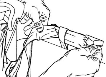
Checking and adding manual transmission fluid (if equipped) 1. Clean the filler plug. 2. Remove the filler plug and inspect the fluid level.
3. Fluid level should be at the bottom of the opening. 4. Add enough fluid through the filler opening so that the fluid level is at the bottom of the opening. 5. Install and tighten the fill plug securely.
Use only fluid that meets Ford specifications. Refer to Maintenance Product Specifications and Capacities in this chapter.
378
2008 F-250/350/450/550 (f23) Owners Guide (post-2002-fmt) USA (fus)
Maintenance and Specifications
TRANSFER CASE FLUID (IF EQUIPPED) 1. Clean the filler plug. 2. Remove the filler plug and inspect the fluid level.
3. Add only enough fluid through the filler opening so that the fluid level is at the bottom of the opening.
Use only fluid that meets Ford specifications. Refer to Maintenance Product Specifications and Capacities in this chapter.
379
2008 F-250/350/450/550 (f23) Owners Guide (post-2002-fmt) USA (fus)
Maintenance and Specifications
DRIVELINE UNIVERSAL JOINT AND SLIP YOKE If the original universal joints are replaced with universal joints equipped with grease fittings, lubrication will be necessary. Refer to the replacement universal joint manufacturer’s recommendation for lubrication type and maintenance intervals.
AIR FILTER MAINTENANCE Refer to the scheduled maintenance information for the appropriate intervals for changing the air filter element. When changing the air filter element, use only the Motorcraft air filter element listed. Refer to Motorcraft part numbers in this chapter. The following procedure is for vehicles equipped with a gasoline engine. If your vehicle is equipped with a diesel engine, refer to the 6.0 and 6.4
Liter Power Stroke Direct Injection Turbo Diesel Owner’s Guide Supplement. Note: Do not start your engine with the air cleaner removed and do not remove it while the engine is running.Changing the air filter element 1. Loosen clamp and disconnect sensor.
380
2008 F-250/350/450/550 (f23) Owners Guide (post-2002-fmt) USA (fus)
Maintenance and Specifications
2. Release three retainer clamps.
3. Pull air filter cover toward passenger side of vehicle and up to release the tabs. Lift air filter element up and out of housing. The air filter box needs to be free of any debris before installing a new air filter. 4. Install a new air filter element into the tray assembly. 5. Return air filter cover to original position making sure the four tabs are engaged and secure the three clamps. Tighten clamp on air tube and reconnect sensor.
381
2008 F-250/350/450/550 (f23) Owners Guide (post-2002-fmt) USA (fus)
Maintenance and Specifications
BXT-65-650
BXT-65-7505.4L V8/6.8L V10 engines
FA-1883
FG-1011
FL-820-SMOTORCRAFT PART NUMBERS Component Air filter element Fuel filter Oil filter PCV valve Battery (Standard) Battery (Optional) Spark plugs-platinum Remote Automatic Transmission Filter 3, 4
1The PCV valve is a critical emission component. It is one of the items listed in the scheduled maintenance information and is essential to the life and performance of your vehicle and to its emissions system. For PCV valve replacement, see your authorized dealer. Refer to the scheduled maintenance information for the appropriate intervals for changing the PCV valve. Replace the PCV valve with one that meets Ford material and design specifications for your vehicle, such as a Motorcraft or equivalent replacement part. The customer warranty may be void for any damage to the emissions system if such a PCV valve is not used. 2For spark plug replacement, see your authorized dealer. Refer to the scheduled maintenance information for the appropriate intervals for changing the spark plugs. Replace the spark plugs with ones that meet Ford material and design specifications for your vehicle, such as Motorcraft or equivalent replacement parts. The customer warranty may be void for any damage to the engine if such spark plugs are not used. 3Also available with 6.4L diesel engine and TorqShift transmission. Part number is FT-176. 4Also available with 6.4L diesel engine and TorqShift transmission. Part number is FT-175.382
2008 F-250/350/450/550 (f23) Owners Guide (post-2002-fmt) USA (fus)
Maintenance and Specifications
–
–
–
–
–
–
– –
–
–
—
383
2008 F-250/350/450/550 (f23) Owners Guide (post-2002-fmt) USA (fus)
Maintenance and Specifications
’
–
’
—
—
—
—
—
—
—
—
384
2008 F-250/350/450/550 (f23) Owners Guide (post-2002-fmt) USA (fus)
Maintenance and Specifications