- 2008 Ford F 250 Owners Manuals
- Ford F 250 Owners Manuals
- 2012 Ford F 250 Owners Manuals
- Ford F 250 Owners Manuals
- 2000 Ford F 250 Owners Manuals
- Ford F 250 Owners Manuals
- 2001 Ford F 250 Owners Manuals
- Ford F 250 Owners Manuals
- 2006 Ford F 250 Owners Manuals
- Ford F 250 Owners Manuals
- 2015 Ford F 250 Owners Manuals
- Ford F 250 Owners Manuals
- 2010 Ford F 250 Owners Manuals
- Ford F 250 Owners Manuals
- 2004 Ford F 250 Owners Manuals
- Ford F 250 Owners Manuals
- 1999 Ford F 250 Owners Manuals
- Ford F 250 Owners Manuals
- 2007 Ford F 250 Owners Manuals
- Ford F 250 Owners Manuals
- 2009 Ford F 250 Owners Manuals
- Ford F 250 Owners Manuals
- 2013 Ford F 250 Owners Manuals
- Ford F 250 Owners Manuals
- 2016 Ford F 250 Owners Manuals
- Ford F 250 Owners Manuals
- 1998 Ford F 250 Owners Manuals
- Ford F 250 Owners Manuals
- 2005 Ford F 250 Owners Manuals
- Ford F 250 Owners Manuals
- 2011 Ford F 250 Owners Manuals
- Ford F 250 Owners Manuals
- 2014 Ford F 250 Owners Manuals
- Ford F 250 Owners Manuals
- 2002 Ford F 250 Owners Manuals
- Ford F 250 Owners Manuals
- 2003 Ford F 250 Owners Manuals
- Ford F 250 Owners Manuals
- 1996 Ford F 250 Owners Manuals
- Ford F 250 Owners Manuals
- Download PDF Manual
-
and adjusted to the vehicle requirements.
If the tire label shows different tire pressures for the front and rear tires and the vehicle is equipped with TPMS (tire pressure
monitoring system), then the settings for the TPMS sensors need to be updated. Always perform the TPMS reset procedure after tire rotation. If the system is not reset, it may not provide a low tire pressure warning when necessary. See the TPMS reset procedure in this chapter.
218
2008 F-250/350/450/550 (f23) Owners Guide (post-2002-fmt) USA (fus)
Tires, Wheels and Loading
INFORMATION CONTAINED ON THE TIRE SIDEWALL U.S. and Canada Federal regulations require tire manufacturers to place standardized information on the sidewall of all tires. This information identifies and describes the fundamental characteristics of the tire and also provides a U.S. DOT Tire Identification Number for safety standard certification and in case of a recall.
Information on “P” type tires P215/65R15 95H is an example of a tire size, load index and speed rating. The definitions of these items are listed below. (Note that the tire size, load index and speed rating for your vehicle may be different from this example.) 1. P: Indicates a tire, designated by the Tire and Rim Association (T&RA), that may be used for service on cars, SUVs, minivans and light trucks. Note: If your tire size does not begin with a letter this may mean it is designated by either ETRTO (European Tire and Rim Technical Organization) or JATMA (Japan Tire Manufacturing Association). 2. 215: Indicates the nominal width of the tire in millimeters from sidewall edge to sidewall edge. In general, the larger the number, the wider the tire. 3. 65: Indicates the aspect ratio which gives the tire’s ratio of height to width. 4. R: Indicates a “radial” type tire. 5. 15: Indicates the wheel or rim diameter in inches. If you change your wheel size, you will have to purchase new tires to match the new wheel diameter. 6. 95: Indicates the tire’s load index. It is an index that relates to how much weight a tire can carry. You may find this information in your Owner’s Guide. If not, contact a local tire dealer. Note: You may not find this information on all tires because it is not required by federal law.
219
2008 F-250/350/450/550 (f23) Owners Guide (post-2002-fmt) USA (fus)
Tires, Wheels and Loading
7. H: Indicates the tire’s speed rating. The speed rating denotes the speed at which a tire is designed to be driven for extended periods of time under a standard condition of load and inflation pressure. The tires on your vehicle may operate at different conditions for load and inflation pressure. These speed ratings may need to be adjusted for the difference in conditions. The ratings range from 81 mph (130 km/h) to 186 mph (299 km/h). These ratings are listed in the following chart. Note: You may not find this information on all tires because it is not required by federal law.
Letter rating
Speed rating - mph (km/h)
81 mph (130 km/h) 87 mph (140 km/h) 99 mph (159 km/h) 106 mph (171 km/h) 112 mph (180 km/h) 118 mph (190 km/h) 124 mph (200 km/h) 130 mph (210 km/h) 149 mph (240 km/h) 168 mph (270 km/h) 186 mph (299 km/h)
Note: For tires with a maximum speed capability over 149 mph (240
km/h), tire manufacturers sometimes use the letters ZR. For those with a maximum speed capability over 186 mph (299 km/h), tire manufacturers always use the letters ZR. 8. U.S. DOT Tire Identification Number (TIN): This begins with the letters “DOT” and indicates that the tire meets all federal standards. The next two numbers or letters are the plant code designating where it was manufactured, the next two are the tire size code and the last four numbers represent the week and year the tire was built. For example, the numbers 317 mean the 31st week of 1997. After 2000 the numbers go to four digits. For example, 2501 means the 25th week of 2001. The numbers in between are identification codes used for traceability. This information is used to contact customers if a tire defect requires a recall. 9. M+S or M/S: Mud and Snow, or AT: All Terrain, or AS: All Season.220
2008 F-250/350/450/550 (f23) Owners Guide (post-2002-fmt) USA (fus)
Tires, Wheels and Loading
10. Tire Ply Composition and Material Used: Indicates the number of plies or the number of layers of rubber-coated fabric in the tire tread and sidewall. Tire manufacturers also must indicate the ply materials in the tire and the sidewall, which include steel, nylon, polyester, and others. 11. Maximum Load: Indicates the maximum load in kilograms and pounds that can be carried by the tire. Refer to the Tire Label or Safety Compliance Certification Label, which is located on the B-Pillar or the edge of the driver’s door, for the correct tire pressure for your vehicle. 12. Treadwear, Traction and Temperature Grades • Treadwear: The treadwear grade is a comparative rating based on the
wear rate of the tire when tested under controlled conditions on a specified government test course. For example, a tire graded 150
would wear one and one-half (11⁄2) times as well on the government course as a tire graded 100. • Traction: The traction grades, from highest to lowest are AA, A, B,and C. The grades represent the tire’s ability to stop on wet pavement as measured under controlled conditions on specified government test surfaces of asphalt and concrete. A tire marked C may have poor traction performance.
• Temperature: The temperature grades are A (the highest), B and C, representing the tire’s resistance to the generation of heat and its ability to dissipate heat when tested under controlled conditions on a specified indoor laboratory test wheel.
13. Maximum Permissible Inflation Pressure: Indicates the tire manufacturers’ maximum permissible pressure and/or the pressure at which the maximum load can be carried by the tire. This pressure is normally higher than the manufacturer’s recommended cold inflation pressure which can be found on either the Tire Label or Safety Compliance Certification Label which is located on the B-Pillar or the edge of the driver’s door. The cold inflation pressure should never be set lower than the recommended pressure on the vehicle label. The tire suppliers may have additional markings, notes or warnings such as standard load, radial tubeless, etc.
221
2008 F-250/350/450/550 (f23) Owners Guide (post-2002-fmt) USA (fus)
Tires, Wheels and Loading
Additional information contained on the tire sidewall for “LT” type tires “LT” type tires have some additional information beyond those of “P” type tires; these differences are described below. Note: Tire Quality Grades do not apply to this type of tire. 1. LT: Indicates a tire, designated by the Tire and Rim Association (T&RA), that is intended for service on light trucks. 2. Load Range/Load Inflation Limits: Indicates the tire’s load-carrying capabilities and its inflation limits. 3. Maximum Load Dual lb. (kg) at psi (kPa) cold: Indicates the maximum load and tire pressure when the tire is used as a dual; defined as four tires on the rear axle (a total of six or more tires on the vehicle). 4. Maximum Load Single lb. (kg) at psi (kPa) cold: Indicates the maximum load and tire pressure when the tire is used as a single; defined as two tires (total) on the rear axle.
222
2008 F-250/350/450/550 (f23) Owners Guide (post-2002-fmt) USA (fus)
Tires, Wheels and Loading
Information on “T” type tires “T” type tires have some additional information beyond those of “P” type tires; these differences are described below: T145/80D16 is an example of a tire size. Note: The temporary tire size for your vehicle may be different from this example. Tire Quality Grades do not apply to this type of tire. 1. T: Indicates a type of tire, designated by the Tire and Rim Association (T&RA), that is intended for temporary service on cars, SUVs, minivans and light trucks. 2. 145: Indicates the nominal width of the tire in millimeters from sidewall edge to sidewall edge. In general, the larger the number, the wider the tire. 3. 80: Indicates the aspect ratio which gives the tire’s ratio of height to width. Numbers of 70 or lower indicate a short sidewall. 4. D: Indicates a “diagonal” type tire. R: Indicates a “radial” type tire. 5. 16: Indicates the wheel or rim diameter in inches. If you change your wheel size, you will have to purchase new tires to match the new wheel diameter.
Location of the Tire Label or Safety Compliance Certification Label You will find a Tire Label or Safety Compliance Certification Label containing tire inflation pressure by tire size and other important information located on the B-Pillar or the edge of the driver’s door. Refer to the payload description and graphic in the Vehicle loading — with and without a trailer section.
223
2008 F-250/350/450/550 (f23) Owners Guide (post-2002-fmt) USA (fus)
Tires, Wheels and Loading
TIRE PRESSURE MONITORING SYSTEM (TPMS) (IF EQUIPPED) Each tire, including the spare (if provided), should be checked monthly when cold and inflated to the inflation pressure recommended by the vehicle manufacturer on the vehicle placard or tire inflation pressure label. (If your vehicle has tires of a different size than the size indicated on the vehicle placard or tire inflation pressure label, you should determine the proper tire inflation pressure for those tires.) As an added safety feature, your vehicle has been equipped with a tire pressure monitoring system (TPMS) that illuminates a low tire pressure telltale when one or more of your tires is significantly under-inflated. Accordingly, when the low tire pressure telltale illuminates, you should stop and check your tires as soon as possible, and inflate them to the proper pressure. Driving on a significantly under-inflated tire causes the tire to overheat and can lead to tire failure. Under-inflation also reduces fuel efficiency and tire tread life, and may affect the vehicle’s handling and stopping ability. Please note that the TPMS is not a substitute for proper tire maintenance, and it is the driver’s responsibility to maintain correct tire pressure, even if under-inflation has not reached the level to trigger illumination of the TPMS low tire pressure telltale. Your vehicle has also been equipped with a TPMS malfunction indicator to indicate when the system is not operating properly. The TPMS malfunction indicator is combined with the low tire pressure telltale. When the system detects a malfunction, the telltale will flash for approximately one minute and then remain continuously illuminated. This sequence will continue upon subsequent vehicle start-ups as long as the malfunction exists. When the malfunction indicator is illuminated, the system may not be able to detect or signal low tire pressure as intended. TPMS malfunctions may occur for a variety of reasons, including the installation of replacement or alternate tires or wheels on the vehicle that prevent the TPMS from functioning properly. Always check the TPMS malfunction telltale after replacing one or more tires or wheels on your vehicle to ensure that the replacement or alternate tires and wheels allow the TPMS to continue to function properly.
224
2008 F-250/350/450/550 (f23) Owners Guide (post-2002-fmt) USA (fus)
Tires, Wheels and Loading
The Tire Pressure Monitoring System complies with part 15 of the FCC rules and with RSS-210 of Industry Canada. Operation is subject to the following two conditions: (1) This device may not cause harmful interference, and (2) This device must accept any interference received, including interference that may cause undesired operation.
The Tire Pressure Monitoring System is NOT a substitute for manually checking tire pressure. The tire pressure should be
checked periodically (at least monthly) using a tire gauge, see Inflating your tires in this chapter. Failure to properly maintain your tire pressure could increase the risk of tire failure, loss of control, vehicle rollover and personal injury.
Changing tires with TPMS Each road tire is equipped with a tire pressure sensor fastened to the inside rim of the wheel. The pressure sensor is covered by the tire and is not visible unless the tire is removed. The pressure sensor is located opposite (180 degrees) from the valve stem. Care must be taken when changing the tire to avoid damaging the sensor. It is recommended that you always have your tires serviced by an authorized dealer. The tire pressure should be checked periodically (at least monthly) using an accurate tire gauge, refer to Inflating your tires in this chapter.
2008 F-250/350/450/550 (f23) Owners Guide (post-2002-fmt) USA (fus)
225
Tires, Wheels and Loading
Understanding your Tire Pressure Monitoring System (TPMS) The Tire Pressure Monitoring System measures pressure in your four road tires and sends the tire pressure readings to your vehicle. The Low Tire Warning Lamp will turn ON if the tire pressure is significantly low. Once the light is illuminated, your tires are under inflated and need to be inflated to the manufacturer’s recommended tire pressure. Even if the light turns ON and a short time later turns OFF, your tire pressure still needs to be checked. Visit www.checkmytires.org for additional information. When your temporary spare tire is installed When one of your road tires needs to be replaced with the temporary spare, the TPMS system will continue to identify an issue to remind you that the damaged road wheel/tire needs to be repaired and put back on your vehicle. To restore the full functionality of the Tire Pressure Monitoring System, have the damaged road wheel/tire repaired and remounted on your vehicle. For additional information, refer to Changing tires with TPMS in this section.
226
2008 F-250/350/450/550 (f23) Owners Guide (post-2002-fmt) USA (fus)
Tires, Wheels and Loading
When you believe your system is not operating properly The main function of the Tire Pressure Monitoring System is to warn you when your tires need air. It can also warn you in the event the system is no longer capable of functioning as intended. Please refer to the following chart for information concerning your Tire Pressure Monitoring System:
Possible cause Customer Action Required
Low Tire Pressure Warning Light Solid Warning Light Tire(s)
under-inflated
1. Check your tire pressure to ensure tires are properly inflated; refer to Inflating your tires in this chapter. 2. After inflating your tires to the manufacturer’s recommended inflation pressure as shown on the Tire Label (located on the edge of driver’s door or the B-Pillar), the vehicle must be driven for at least two minutes over 20 mph (32 km/h) before the light will turn OFF. Your temporary spare tire is in use. Repair the damaged road wheel/tire and reinstall it on the vehicle to restore system functionality. For a description on how the system functions, refer to When your temporary spare tire is installed in this section. If your tires are properly inflated and your spare tire is not in use and the light remains ON, have the system inspected by your authorized dealer. On vehicles with different front and rear tire pressures, the TPMS system must be retrained following every tire rotation. Refer to Tire rotation in this chapter.
227
Spare tire in use
TPMS malfunction
Tire rotation without sensor training
2008 F-250/350/450/550 (f23) Owners Guide (post-2002-fmt) USA (fus)
Tires, Wheels and Loading
Low Tire Pressure Warning Light Flashing Warning Light
Possible cause Customer Action Required
Spare tire in use
TPMS malfunction
Your temporary spare tire is in use. Repair the damaged road wheel and re-mount it on the vehicle to restore system functionality. For a description of how the system functions under these conditions, refer to When your temporary spare tire is installed in this section. If your tires are properly inflated and your spare tire is not in use and the TPMS warning light still flashes, have the system inspected by your authorized dealer.
When inflating your tires When putting air into your tires (such as at a gas station or in your garage), the Tire Pressure Monitoring System may not respond immediately to the air added to your tires. It may take up to two minutes of driving over 20 mph (32 km/h) for the light to turn OFF after you have filled your tires to the recommended inflation pressure. How temperature affects your tire pressure The Tire Pressure Monitoring System (TPMS) monitors tire pressure in each pneumatic tire. While driving in a normal manner, a typical passenger tire inflation pressure may increase approximately 2 to 4 psi (14 to 28 kPa) from a cold start situation. If the vehicle is stationary over night with the outside temperature significantly lower than the daytime temperature, the tire pressure may decrease approximately 3 psi (20.7 kPa) for a drop of 30° F (16.6°C) in ambient temperature. This lower pressure value may be detected by the TPMS as being significantly lower than the recommended inflation pressure and activate the TPMS warning for low tire pressure. If the low tire pressure warning light is ON, visually check each tire to verify that no tire is flat. (If one or more tires are flat, repair as necessary.) Check air pressure in the road tires. If any tire is under-inflated, carefully drive the vehicle to the nearest location where air can be added to the tires. Inflate all the tires to the recommended inflation pressure.
228
2008 F-250/350/450/550 (f23) Owners Guide (post-2002-fmt) USA (fus)
Tires, Wheels and Loading
TPMS reset procedure (if applicable) This procedure is only required after tire rotation on vehicles with different front and rear tire pressures.
To determine if your vehicle requires two different pressures - one for the front tires and one for the rear tires - refer to the
Safety Compliance Certification Label or Tire Label which is located on the B-Pillar or the edge of the driver’s door. See Vehicle Loading in this chapter for more information.
Overview To provide the vehicle’s load carrying capability, some trucks require different recommended tire pressures in the front tires as compared to the rear tires. The Tire Pressure Monitoring System (TPMS) equipped on these vehicles is designed to illuminate the Low Tire Pressure Warning indicator at two different pressures; one for the front tires and one for the rear tires. Since tires need to be rotated to provide consistent performance and maximum tire life, the Tire Pressure Monitoring System needs to know when the tires are rotated to determine which set of tires are on the front and which are on the rear. With this information, the system can detect and properly warn of low tire pressures.
Always perform the TPMS reset procedure after tire rotation. If the system is not reset, it may not provide a low tire pressure
warning when necessary.
229
2008 F-250/350/450/550 (f23) Owners Guide (post-2002-fmt) USA (fus)
Tires, Wheels and Loading
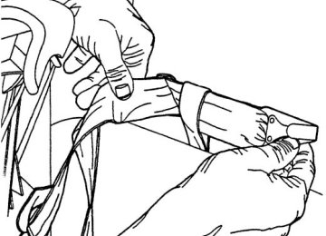
TPMS reset tool A special TPMS reset tool has been provided with your vehicle to reset your TPMS after tire rotation. The tool is located with your Owner’s Guide materials.
Please take the tool with the provided Velcro威 strip on the back and mount it in the bottom right corner of your Owner’s Guide case (as shown) for safe keeping. If you find that the reset tool was not provided when delivered, has been lost or no longer functions (the battery is not replaceable), please contact your authorized dealer to obtain a replacement. To verify that your TPMS reset tool is working, press and release the button on the center of the TPMS tool. The red light should illuminate and remain on for approximately five (5) seconds. If the light does not illuminate, the tool needs to be replaced. TPMS reset tips To reduce the chances of interference from another vehicle, TPMS reset should be performed at least three feet (one meter) away from another Ford Motor Company vehicle undergoing the TPMS reset procedure at the same time. Do not wait more than two (2) minutes between resetting each tire sensor or the system will timeout and the entire procedure will have to be repeated on all four wheels. A double horn chirp indicates the need to repeat the procedure. TPMS reset procedure Note: It is recommended that you read the entire procedure before attempting. Note: To enter the reset mode, Steps 1–5 MUST be completed within 60
seconds. 1. The key must be in the ignition and the ignition turned to OFF/LOCK. Press and release the brake pedal. 2. Cycle the ignition from OFF/LOCK to RUN three (3) times ending in the RUN position. DO NOT start the engine.230
2008 F-250/350/450/550 (f23) Owners Guide (post-2002-fmt) USA (fus)
Tires, Wheels and Loading
3. Press and hold the brake pedal for two (2) seconds, then release. 4. Turn the ignition to OFF/LOCK (DO NOT remove the key.) 5. Cycle the ignition from OFF/LOCK to RUN three (3) times ending in RUN. DO NOT start the engine. If reset mode has been entered successfully, the horn will sound once, the TPMS indicator will flash and the message center will display TRAIN LF TIRE. If after repeated attempts to enter reset mode, the horn does not sound, the TPMS indicator does not flash and the message center does not display TRAIN LF TIRE, seek service from your authorized dealer. TPMS reset sequence The TPMS system needs to be reset starting with the left front tire in the following clockwise order: 1. Left front tire 2. Right front tire 3. Right rear tire 4. Left rear tire
231
2008 F-250/350/450/550 (f23) Owners Guide (post-2002-fmt) USA (fus)
Tires, Wheels and Loading
1. Left front tire: Place the TPMS reset tool against the left front tire where the tire meets the rim, opposite from the valve stem (1) as shown. This is where the sensor is located inside the rim. The tool needs to be held against the tire sidewall opposite the valve stem as illustrated with the arrow on the tool pointing towards the rim; do not use the tool with the arrow pointing away from the rim as it may not activate the sensor. 2. Press and release the green button and hold the tool to the tire sidewall until the horn sounds. The red light on the TPMS reset tool will illuminate while the tool is active. The horn will sound once within 10
seconds to indicate the process was successful. Note: If a double horn chirp is heard, repeat the procedure. If a single horn chirp is not heard, move the vehicle to rotate the wheels at least a 1⁄4-turn and repeat the procedure. If the horn does not sound while attempting to reset any wheel, seek service from your authorized dealer. 3. Perform Steps 1 and 2 on the right front, right rear and finally the left rear tires. Successful completion of the reset procedure can be verified by turning the ignition to OFF without the horn sounding. If two short beeps are heard, the reset procedure was unsuccessful and must be repeated. If after repeating the procedure two short beeps are heard when the key is turned to OFF, seek assistance from your authorized dealer.232
2008 F-250/350/450/550 (f23) Owners Guide (post-2002-fmt) USA (fus)
Tires, Wheels and Loading
Rotation, pressure adjustment and TPMS reset example The following example describes all the major steps involved in rotating tires on a vehicle with different front and rear tire pressures. It illustrates that the TPMS reset procedure needs to follow tire rotation and pressure adjustment to avoid a possible false low tire warning. Example: A particular vehicle has the following recommended tire pressures: 50 psi (345 kPa) front; 80 psi (552 kPa) rear. Note: For your vehicle’s pressure, refer to the Safety Compliance Certification Label located on the B-Pillar or the edge of your vehicle’s driver’s door. Before tire rotation Sensor 1: 50 psi Sensor 2: 50 psi Sensor 3: 80 psi Sensor 4: 80 psi
Tire rotation using the recommended sequence (front tires at top of diagram)
233
2008 F-250/350/450/550 (f23) Owners Guide (post-2002-fmt) USA (fus)
Tires, Wheels and Loading
Sensor position following tire rotation Sensor 1: 50 psi Sensor 2: 50 psi Sensor 3: 80 psi Sensor 4: 80 psi
Pressure adjustment without the required TPMS reset procedure Sensor 1: 80 psi Sensor 2: 80 psi Sensor 3: 50 psi Sensor 4: 50 psi
In this situation, the TPMS warning light will come on.
If the TPMS reset procedure is not performed after tire rotation and air pressure adjustment, the TPMS telltale may illuminate for a false low tire pressure condition. As in this example, the rear tires rotated to the front and properly inflated to 50 psi (345 kPa) for the front axle would falsely illuminate the low tire warning indicator as they are still trained for the rear positions which require 80 psi (552 kPa).
234
2008 F-250/350/450/550 (f23) Owners Guide (post-2002-fmt) USA (fus)
Tires, Wheels and Loading
Rotation, pressure adjustment and successful completion of the TPMS reset procedure Sensor 1: 80 psi Sensor 2: 80 psi Sensor 3: 50 psi Sensor 4: 50 psi Tire rotation and air pressure adjustment followed by sensor resetting will ensure the system is properly programmed for vehicles with different front and rear tire pressures and reduce the risk of a false low tire warning. In this situation, the TPMS warning light will be off. SNOW TIRES AND CHAINS
Snow tires must be the same size and grade as the tires you currently have on your vehicle.
Note: Do not use snow chains on front tires of vehicles with 20” wheels and tires. The tires on your vehicle have all weather treads to provide traction in rain and snow. However, in some climates, you may need to use snow tires and chains. If you need to use chains, it is recommended that steel wheels (of the same size and specifications) be used, as chains may chip aluminum wheels. Follow these guidelines when using snow tires and chains: • Use only SAE Class S chains. • Install chains securely, verifying that the chains do not touch any • Drive cautiously. If you hear the chains rub or bang against your
wiring, brake lines or fuel lines.
vehicle, stop and re-tighten the chains. If this does not work, remove the chains to prevent damage to your vehicle.
• If possible, avoid fully loading your vehicle. • Remove the tire chains when they are no longer needed. Do not use • The suspension insulation and bumpers will help prevent vehicle damage. Do not remove these components from your vehicle when using snow tires and chains.
tire chains on dry roads.
235
2008 F-250/350/450/550 (f23) Owners Guide (post-2002-fmt) USA (fus)
Tires, Wheels and Loading
VEHICLE LOADING – WITH AND WITHOUT A TRAILER This section will guide you in the proper loading of your vehicle and/or trailer, to keep your loaded vehicle weight within its design rating capability, with or without a trailer. Properly loading your vehicle will provide maximum return of vehicle design performance. Before loading your vehicle, familiarize yourself with the following terms for determining your vehicle’s weight ratings, with or without a trailer, from the vehicle’s Tire Label or Safety Compliance Certification Label: Base Curb Weight – is the weight of the vehicle including a full tank of fuel and all standard equipment. It does not include passengers, cargo, or optional equipment. Vehicle Curb Weight – is the weight of your new vehicle when you picked it up from your authorized dealer plus any aftermarket equipment.
Payload – is the combined weight of cargo and passengers that the vehicle is carrying. The maximum payload for your vehicle can be found on the Tire Label (vehicles exported outside the U.S. and Canada may not have a Tire Label) on the B-Pillar or the edge of the driver’s door. Look for “THE COMBINED WEIGHT OF OCCUPANTS AND CARGO SHOULD NEVER EXCEED XXX kg OR XXX lb.” for maximum payload. The payload listed on the Tire Label is the maximum payload for the vehicle as built by the assembly plant. If any aftermarket or authorized dealer installed equipment has been installed on the vehicle, the weight of the equipment must be subtracted from the payload listed on the Tire Label in order to determine the new payload.
236
2008 F-250/350/450/550 (f23) Owners Guide (post-2002-fmt) USA (fus)
Tires, Wheels and Loading
The appropriate loading capacity of your vehicle can be limited either by volume capacity (how much space is available) or by payload capacity (how much weight the vehicle should carry). Once you have reached the maximum payload of your vehicle, do not add more cargo, even if there is space available. Overloading or improperly loading your vehicle can contribute to loss of vehicle control and vehicle rollover.
Example only:
237
2008 F-250/350/450/550 (f23) Owners Guide (post-2002-fmt) USA (fus)
Tires, Wheels and Loading
Cargo Weight – includes all weight added to the Base Curb Weight, including cargo and optional equipment. When towing, trailer tongue load or king pin weight is also part of cargo weight. GAW (Gross Axle Weight) – is the total weight placed on each axle (front and rear) – including vehicle curb weight and all payload. GAWR (Gross Axle Weight Rating) – is the maximum allowable weight that can be carried by a single axle (front or rear). These numbers are shown on the Safety Compliance Certification Label located on the B-Pillar or the edge of the driver’s door. The total load on each axle must never exceed its GAWR.
Exceeding the Safety Compliance Certification Label axle weight rating limits could result in substandard vehicle handling or
performance, engine, transmission and/or structural damage, serious damage to the vehicle, loss of control and personal injury.
Note: For trailer towing information refer to Trailer towing found in this chapter or the RV and Trailer Towing Guide provided by your authorized dealer.
238
2008 F-250/350/450/550 (f23) Owners Guide (post-2002-fmt) USA (fus)
Tires, Wheels and Loading
GVW (Gross Vehicle Weight) – is the Vehicle Curb Weight + cargo + passengers. GVWR (Gross Vehicle Weight Rating) – is the maximum allowable weight of the fully loaded vehicle (including all options, equipment, passengers and cargo). The GVWR is shown on the Safety Compliance Certification Label located on the B-Pillar or the edge of the driver’s door. The GVW must never exceed the GVWR.
GCW (Gross Combined Weight) – is the weight of the loaded vehicle (GVW) plus the weight of the fully loaded trailer. GCWR (Gross Combined Weight Rating) – is the maximum allowable weight of the vehicle and the loaded trailer – including all cargo and
239
2008 F-250/350/450/550 (f23) Owners Guide (post-2002-fmt) USA (fus)
Tires, Wheels and Loading
passengers – that the vehicle can handle without risking damage. (Important: The towing vehicles’ braking system is rated for operation at GVWR, not at GCWR. Separate functional brakes should be used for safe control of towed vehicles and for trailers where the GCW of the towing vehicle plus the trailer exceed the GVWR of the towing vehicle. The GCW must never exceed the GCWR. Maximum Loaded Trailer Weight – is the highest possible weight of a fully loaded trailer the vehicle can tow. It assumes a vehicle with only mandatory options, no cargo (internal or external), a tongue load of 10–15% (conventional trailer) or king pin weight of 15–25% (fifth wheel trailer), and driver only (150 lb. [68 kg]). Consult your authorized dealer (or the RV and Trailer Towing Guide provided by your authorized dealer) for more detailed information. Tongue Load or Fifth Wheel King Pin Weight – refers to the amount of the weight that a trailer pushes down on a trailer hitch. Examples: For a 5,000 lb. (2,268 kg) conventional trailer, multiply 5,000
by 0.10 and 0.15 to obtain a proper tongue load range of 500 to 750 lb. (227 to 340 kg). For an 11,500 lb. (5,216 kg) fifth wheel trailer, multiply by 0.15 and 0.25 to obtain a proper king pin load range of 1,725 to 2,875 lb. (782 to 1,304 kg)Do not exceed the GVWR or the GAWR specified on the Safety Compliance Certification Label.
Do not use replacement tires with lower load carrying capacities than the originals because they may lower the vehicle’s GVWR and GAWR limitations. Replacement tires with a higher limit than the originals do not increase the GVWR and GAWR limitations.
Exceeding any vehicle weight rating limitation could result in serious damage to the vehicle and/or personal injury.
Steps for determining the correct load limit: 1. Locate the statement “The combined weight of occupants and cargo should never exceed XXX kg or XXX lbs.” on your vehicle’s placard. 2. Determine the combined weight of the driver and passengers that will be riding in your vehicle. 3. Subtract the combined weight of the driver and passengers from XXX kg or XXX lbs.
240
2008 F-250/350/450/550 (f23) Owners Guide (post-2002-fmt) USA (fus)
Tires, Wheels and Loading
4. The resulting figure equals the available amount of cargo and luggage load capacity. For example, if the “XXX” amount equals 1,400 lbs. and there will be five 150 lb. passengers in your vehicle, the amount of available cargo and luggage load capacity is 650 lbs. (1,400–750
(5 x 150) = 650 lb.). In metric units (635–340 (5 x 68) = 295 kg.) 5. Determine the combined weight of luggage and cargo being loaded on the vehicle. That weight may not safely exceed the available cargo and luggage load capacity calculated in Step 4. 6. If your vehicle will be towing a trailer, load from your trailer will be transferred to your vehicle. Consult this manual to determine how this reduces the available cargo and luggage load capacity of your vehicle. The following gives you a few examples on how to calculate the available amount of cargo and luggage load capacity: • Another example for your vehicle with 1,400 lb. (635 kg) of cargo and luggage capacity. You decide to go golfing. Is there enough load capacity to carry you, 4 of your friends and all the golf bags? You and four friends average 220 lb. (99 kg) each and the golf bags weigh approximately 30 lb. (13.5 kg) each. The calculation would be: 1,400 – (5 x 220) – (5 x 30) = 1,400 – 1,100 – 150 = 150 lb. Yes, you have enough load capacity in your vehicle to transport four friends and your golf bags. In metric units, the calculation would be: 635 kg - (5 x 99 kg) - (5 x 13.5 kg) = 635 – 495 – 67.5 = 72.5 kg.• A final example for your vehicle with 1,400 lb. (635 kg) of cargo and luggage capacity. You and one of your friends decide to pick up cement from the local home improvement store to finish that patio you have been planning for the past 2 years. Measuring the inside of the vehicle with the rear seat folded down, you have room for 12-100 lb. (45 kg) bags of cement. Do you have enough load capacity to transport the cement to your home? If you and your friend each weigh 220 lb. (99 kg), the calculation would be: 1,400 – (2 x 220) – (12 x 100) = 1,400 – 440 – 1,200 = – 240 lb. No, you do not have enough cargo capacity to carry that much weight. In metric units, the calculation would be: 635 kg - (2 x 99 kg) - (12 x 45 kg) = 635 – 198
– 540 = – 103 kg. You will need to reduce the load weight by at least 240 lb. (104 kg). If you remove 3-100 lb. (45 kg) cement bags, then the load calculation would be: 1,400 – (2 x 220) – (9 x 100) = 1,400 – 440 – 900 = 60 lb. Now you have the load capacity to transport the cement and your friend home. In metric units, the calculation would be: 635 kg - (2 x 99 kg) - (9 x 45 kg) = 635 – 198 – 405 = 32 kg.241
2008 F-250/350/450/550 (f23) Owners Guide (post-2002-fmt) USA (fus)
Tires, Wheels and Loading
The above calculations also assume that the loads are positioned in your vehicle in a manner that does not overload the Front or the Rear Gross Axle Weight Rating specified for your vehicle on the Tire Label or Safety Compliance Certification Label found on the edge of the driver’s door.
Special loading instructions for owners of pickup trucks and utility-type vehicles
For important information regarding safe operation of this type of vehicle, see the Preparing to drive your vehicle section in
the Driving chapter of this owner guide.
Loaded vehicles may handle differently than unloaded vehicles. Extra precautions, such as slower speeds and increased stopping
distance, should be taken when driving a heavily loaded vehicle.
Your vehicle can haul more cargo and people than most passenger cars. Depending upon the type and placement of the load, hauling cargo and people may raise the center of gravity of the vehicle.
TRAILER TOWING Note: The trailer towing charts in this section apply to vehicles equipped with gasoline engines; for vehicles equipped with diesel engines, refer to your 6.0 and 6.4 Liter Power Stroke Direct Injection Turbo Diesel Owner’s Guide Supplement. Your vehicle may tow a Conventional/Class IV trailer or fifth wheel trailer provided the maximum trailer weight is less than or equal to the maximum trailer weight listed for your engine and rear axle ratio on the following charts. To calculate your maximum trailer weight: For pickup trucks: Take curb weight, hitch hardware and the driver’s weight, then subtract them from the GCWR listed for your vehicle series, engine, transmission and drive axle ratio (refer to the chart/table in the following text). This calculation will give you the maximum trailer weight possible for your vehicle. For chassis cabs and pickup trucks with aftermarket equipment: Weigh your vehicle at a certified scale and subtract this actual curb weight, hitch hardware, and the driver’s weight from the GCWR listed for your vehicle series, engine, transmission and drive axle ratio (refer to the chart/table in the following text). This calculation will give you the maximum trailer weight possible for your vehicle.
242
2008 F-250/350/450/550 (f23) Owners Guide (post-2002-fmt) USA (fus)
Tires, Wheels and Loading
The weight of all additional cargo and passengers must be subtracted from the maximum trailer weight calculated above. Further trailer/hitch restrictions and limitations exist depending on the type of trailer and hitch used. These additional maximum trailer weight and tongue load limitations are listed in the chart/table that follows the listing of GCWRs. Towing a trailer places an additional load on your vehicle’s engine, transmission, axle, brakes, tires and suspension. Inspect these components carefully prior to and after any towing operation. Refer to Transmission fluid temperature gauge in the Instrument Cluster chapter for the transmission fluid temperature information. Note: Do not exceed the GCWR listed for your vehicle on the following chart/table, or the GVWR, GAWR or tire ratings specified on the Tire Label or Safety Compliance Certification Label.
Towing trailers beyond the maximum recommended trailer weight which exceeds the limit of the vehicle’s GCWR, GVWR,
GAWR or tire ratings could result in engine damage, transmission damage, structural damage, loss of vehicle control, vehicle rollover and personal injury.
Maximum GCWR - lb. (kg.)
Engine
Rear axle
ratio
Manual
transmission
Automatic
transmission
5.4L
6.8L
5.4L
6.8L
F–250 Pick-up
3.73
4.10
4.10
4.3015000 (6804) 17000 (7711) 20000 (9072) 22000 (9979)
16000 (7257) 18000 (8165) 21000 (9525) 22500 (10206)
F–350 Single Rear Wheel (SRW) Pick-up
3.73
4.10
4.10
4.3015000 (6804) 17000 (7711) 20000 (9072) 22000 (9979)
16000 (7257) 18000 (8165) 21000 (9525) 23000 (10433)
243
2008 F-250/350/450/550 (f23) Owners Guide (post-2002-fmt) USA (fus)
Tires, Wheels and Loading
Maximum GCWR - lb. (kg.)
Engine
Rear axle
ratio
Manual
transmission
Automatic
transmission
F–350 Dual Rear Wheel (DRW) Pick-up
5.4L 6.8L
5.4L
6.8L
5.4L
6.8L
6.8L
4.10
4.10
4.3017500 (7938) 20500 (9299) 22500 (10206)
18500 (8391) 21500 (9752) 23000 (10433)
F–350 Single Rear Wheel (SRW) Chassis Cab
3.73
4.10
4.1015000 (6804) 17000 (7711) 20000 (9072)
16000 (7257) 18000 (8165) 21000 (9525)
F–350 Dual Rear Wheel (DRW) Chassis Cab
3.73
4.10
4.10
4.3015000 (6804) 17500 (7938) 20500 (9299) 22500 (10206) F–450 Chassis Cab/F–550
26000 (11793)4.88/5.38
16500 (7484) 18500 (8391) 21500 (9752) 23000 (10433)
26000 (11793)
Preparing to tow Use the proper equipment for towing a trailer and make sure it is properly attached to your vehicle. See your authorized dealer or a reliable trailer dealer if you require assistance.
Hitches
ON PICK-UP TRUCKS, the trailer hitch provided on this vehicle enhances collision protection for the fuel system. DO NOT
REMOVE!
Do not use hitches that clamp onto the vehicle’s bumper or attach to the axle. You must distribute the load in your trailer so that 10%–15% for conventional towing or 15%-25% fifth-wheel towing of the total weight of the trailer is on the tongue.
244
2008 F-250/350/450/550 (f23) Owners Guide (post-2002-fmt) USA (fus)
Tires, Wheels and Loading
Integrated hitch rating The standard integrated hitch has two ratings depending on mode of operation: • Weight carrying - requires a draw bar and hitch ball. The draw bar • Weight distributing - requires an aftermarket weight distributing system which includes draw bar, hitch ball, spring bars and snap-up brackets. The vertical tongue load of the trailer is distributed between the truck and the trailer by this system.
supports all the vertical tongue load of the trailer.
Hitch Type
Maximum
Gross Trailer Weight — lb.
(kg)
Maximum
Tongue Weight
— lb. (kg)
6.8L DRW Pickup 2.5” ID without adapter (requires 2.5” drawbar) 6.8L DRW Pickup 2.5” ID with adapter (requires 2” drawbar) All SRW Pickups and 5.4L DRW Pickups 2” receiver
Weight carrying
8000 (3629)
800 (363)
Weight distributing
15000 (6804)
1500 (680)
Weight carrying
6000 (2721)
600 (272)
Weight distributing
12500 (5670)
1250 (567)
Weight carrying
6000 (2721)
600 (272)
Weight distributing
12500 (5670)
1250 (567)
Towing trailers beyond the maximum tongue weight exceeds the limit of the towing system and could result in vehicle structural
damage, loss of vehicle control and personal injury.
Weight distributing hitch When hooking up a trailer using a weight distributing hitch, always use the following procedure: 1. Park the unloaded vehicle on a level surface. With the ignition on and all doors closed, allow the vehicle to stand for several minutes so that it can level. 2. Measure the height of a reference point on the front and rear bumpers at the center of the vehicle.
245
2008 F-250/350/450/550 (f23) Owners Guide (post-2002-fmt) USA (fus)
Tires, Wheels and Loading
3. Attach the trailer to the vehicle and adjust the hitch equalizers so that the front bumper height is within 1⁄2” (13 mm) of the reference point. After proper adjustment, the rear bumper should be no higher than in Step 2. Note: Adjusting a weight distributing hitch so the rear bumper of the vehicle is higher than it was unloaded will defeat the function of the weight distributing hitch and may cause unpredictable handling.
Safety chains Always connect the trailer’s safety chains to the frame or hook retainers of the vehicle hitch. To connect the trailer’s safety chains, cross the chains under the trailer tongue and allow slack for turning corners. If you use a rental trailer, follow the instructions that the rental agency gives to you. Do not attach safety chains to the bumper.
Trailer brakes Electric brakes and manual, automatic or surge-type trailer brakes are safe if installed properly and adjusted to the manufacturer’s specifications. The trailer brakes must meet local and Federal regulations.
If you own a trailer with a hydraulic brake system, do not connect the trailer’s hydraulic brake system directly to your
vehicle’s brake system. The vehicle’s brake system is only designed to carry the appropriate amount of brake fluid for the vehicle alone. Connecting a hydraulic trailer braking system could adversely affect your vehicle’s braking performance.
The braking system of the tow vehicle is rated for operation at the GVWR not GCWR. Integrated trailer brake controller (if equipped) Your vehicle may be equipped with a fully integrated electronic Trailer Brake Controller (TBC). When used properly, the TBC helps ensure smooth and effective trailer braking by powering the trailer’s electric brakes with a proportional output based on the towing vehicle’s brake pressure.
246
2008 F-250/350/450/550 (f23) Owners Guide (post-2002-fmt) USA (fus)
Tires, Wheels and Loading
The Ford TBC has only been verified to be compatible with trailers having electric-actuated drum brakes (one to four axles)
and not hydraulic surge or electric-over-hydraulic types. It is the responsibility of the customer to ensure that the trailer brakes are adjusted appropriately, functioning normally and all electric connections are properly made.
The TBC user interface consists of the following: 1. +/- (GAIN adjustment buttons): Pressing these buttons will adjust the TBC’s power output to the trailer brakes (in 0.5
increments). The GAIN setting can be increased to a maximum of 10.0
or decreased to a minimum of 0 (no trailer braking). Pressing and holding a button will raise or lower the setting continuously. 2. Trailer connection indicator: This lamp indicates trailer electrical connection status. • When a successful trailer connection is detected, the indicator will be • If the electrical connection is lost, the indicator will flash red. If thegreen.
connection is lost while the vehicle is stationary, the indicator will turn off after 30 seconds. If the connection is lost while the vehicle is moving, the indicator will flash until the ignition is turned off, then on again or if there is a reconnection. • If no electrical connection is detected after the ignition is turned on, pressing a GAIN adjustment button will display the GAIN setting. Sliding the manual control will display the GAIN setting, OUTPUT bar graph and light the trailer indicator red.
3. GAIN setting display: Shows the current GAIN setting. This will illuminate when a trailer is connected, flash if the trailer becomes disconnected, or remain off if no trailer is connected. 4. OUTPUT bar graph: When the vehicle’s brake pedal is pushed, or when the manual control is activated, green bar indicators will illuminate to indicate the amount of power going to the trailer brakes relative to the brake pedal or manual control input.
247
2008 F-250/350/450/550 (f23) Owners Guide (post-2002-fmt) USA (fus)
Tires, Wheels and Loading
5. Manual control lever: Slide the control lever to the left to activate power to the trailer’s electric brakes independent of the tow vehicle’s brakes (see the following Procedure for adjusting GAIN section for instructions on proper use of this feature). If the manual control is activated while the brake is also applied, the greater of the two inputs determines the power sent to the trailer brakes. • Stop Lamps: Activating the TBC manual control lever will illuminate both the trailer brake lamps and the tow vehicle brake lamps except the Center High-Mount Stop Lamp (presuming proper trailer electrical connection). Pressing the vehicle brake pedal will also illuminate both trailer and vehicle brake lamps.
GAIN: The GAIN setting is used to set the TBC for the specific towing condition and should be changed as towing conditions change. Changes to towing conditions include trailer load, vehicle load, road conditions and weather. The GAIN should be set to provide the maximum trailer braking assistance while ensuring the trailer wheels do not lock when braking. Locked trailer wheels may lead to trailer instability. Procedure for adjusting GAIN: Note: This should only be performed in a traffic free environment at speeds of approximately 20–25 mph (30–40 km/h). 1. Make sure the trailer brakes are in good working condition, functioning normally, and properly adjusted. See your trailer dealer if necessary. 2. Hook-up the trailer and make the electrical connections according to the trailer manufacturer’s instructions. 3. When a trailer with electric brakes is plugged in, the trailer connection indicator will illuminate green on the TBC and the GAIN setting display will illuminate. 4. Use the GAIN adjustment (+/-) buttons to increase or decrease the GAIN setting to the desired starting point. (A GAIN setting of 6.0 is a good starting point for heavier loads.) 5. In a traffic-free environment, tow the trailer on a dry, level surface at a speed of 20–25 mph (30–40 km/h) and squeeze the manual control lever completely.
248
2008 F-250/350/450/550 (f23) Owners Guide (post-2002-fmt) USA (fus)
Tires, Wheels and Loading
6. If the trailer wheels lock-up (indicated by squealing tires), reduce the GAIN setting; if the trailer wheels turn freely, increase the GAIN setting. Repeat Steps 5 and 6 until the GAIN setting is at a point just below trailer wheel lock-up. If towing a heavier trailer, trailer wheel lockup may not be attainable even with the maximum GAIN setting of 10. Explanation of instrument cluster messages: The TBC interacts with the instrument cluster message center. These messages, accompanied by a single chime, will be displayed when the TBC determines a malfunction in the trailer connection, TBC system, or in the trailer. These messages are listed below: TRAILER DISCONNECTED (if equipped with message center) or CHECK TRAILER (if equipped with mini message center): This message is displayed when a trailer connection was determined and then a disconnection, either intentionally or unintentionally, has been sensed during a given ignition cycle. It is also displayed if a trailer fault occurs causing the trailer to appear disconnected. This message is also displayed during manual activation without a trailer connected. TBC FAULT: This message is displayed in response to faults sensed by the TBC. In the event this message is seen, please take your vehicle to an authorized dealer for diagnosis and repair. The TBC may still function, but performance may be degraded. WIRING FAULT ON TRAILER: The TBC is capable of determining certain faults in the vehicle wiring and trailer wiring/brake system. These faults do not mean there is anything wrong with the TBC. This message is displayed when one of the following faults has occurred: • Short circuit on the electric brake output wire: If the TRAILER FAULT message is displayed with no trailer connected, the problem is with the vehicle wiring from the TBC to the 7–pin connector in the bumper. If the message is only displayed with a trailer connected, the problem is related to the trailer wiring; consult your trailer dealer for assistance. This can be a short to ground (i.e., chaffed wire) or a short to voltage (i.e., pulled pin on trailer emergency break-away battery) or trailer brakes drawing too much current.
Note: Your TBC can be diagnosed by your authorized dealer to determine exactly which trailer fault has occurred; however, if the fault is with the trailer this diagnosis is not covered under your Ford warranty. Points to Remember: • Remember to adjust gain setting before using the TBC for the first
time.
249
2008 F-250/350/450/550 (f23) Owners Guide (post-2002-fmt) USA (fus)
Tires, Wheels and Loading • Readjust GAIN setting on the TBC (according to procedure above)
whenever road, weather and trailer or vehicle loading conditions change from those that existed when the gain was initially set. • The sliding lever on the TBC should be used only for manual
activation of trailer brakes to assist with proper adjustment of the GAIN. Misuse, such as application during trailer sway, could cause instability of trailer and/or tow vehicle.
• Avoid towing in adverse weather conditions. The TBC does not provide anti-lock control of the trailer wheels. Trailer wheels can lock-up on slippery surfaces, resulting in reduced stability of trailer and tow vehicle. • The TBC interacts with the brake system of the vehicle, including
ABS, in order to reduce the likelihood of trailer wheel lockup. Therefore, if these systems are not functioning properly the TBC may not function at full performance.
• When the vehicle is turned off, the TBC Output is disabled and the display is shut down. Reactivation of the ignition from 3 (OFF) to 4
(ON) will awaken the TBC module.• The TBC is only a factory or dealer installed item. Ford is not
responsible for warranty or performance of the TBC due to misuse or customer installation.
• Do not attempt removal of the TBC without consulting the
Workshop Manual. Damage to the unit may result.
Trailer lamps Trailer lamps are required on most towed vehicles. Make sure all running lights, brake lights, turn signals and hazard lights are working. See your authorized dealer or trailer rental agency for proper instructions and equipment for hooking up trailer lamps.
Using a step bumper (if equipped) The rear bumper is equipped with an integral hitch and only requires a ball with a one inch (2.5 cm) shank diameter. The bumper has a 5,000
lb. (2,270 kg) trailer weight and 500 lb. (227 kg) tongue weight capacity. If it is necessary to relocate the trailer hitch ball position, a frame-mounted trailer hitch must be installed.250
2008 F-250/350/450/550 (f23) Owners Guide (post-2002-fmt) USA (fus)
Tires, Wheels and Loading
Driving while you tow When towing a trailer: • Do not drive faster than 70 mph (113 km/h) during the first 500 miles (800 km) of trailer towing and don’t make full-throttle starts. • Turn off the speed control. The speed control may shut off automatically when you are towing on long, steep grades. • Consult your local motor vehicle speed regulations for towing a trailer. • To eliminate excessive transmission shifting, activate the Tow/Haul feature. This will also assist in transmission cooling. (For additional information, refer to the Understanding the shift positions of the 5–speed automatic transmission section in the Driving chapter. • Anticipate stops and brake gradually. • Do not exceed the GCWR rating or transmission damage may occur. • Your vehicle may be equipped with a temporary or conventional spare tire. If the spare tire is different in size (diameter and/or width), tread type (All-Season or All-Terrain) or is from a different manufacturer other than the road tires on your vehicle, your spare tire is considered “temporary”. Consult information on the spare Tire Label or Safety Compliance Certification Label for limitations when using.
Servicing after towing If you tow a trailer for long distances, your vehicle will require more frequent service intervals. Refer to your scheduled maintenance information for more information.
are securely fastened.
Trailer towing safety tips General • Ensure that the trailer, safety chains and 7–pin electrical connectors • Make sure the truck receiver, draw bar, and coupler are properly • Check rear view and side mirrors for proper visibility especially when • When towing, operate the vehicle at lower speeds than you would
towing trailer wider than the truck.
connected and adjusted.
when not towing a trailer. The likelihood of trailer sway is greater at higher speeds.
251
2008 F-250/350/450/550 (f23) Owners Guide (post-2002-fmt) USA (fus)
Tires, Wheels and Loading • If you will be towing a trailer frequently in hot weather, hilly
conditions, at GCWR, or any combination of these factors, consider refilling your rear axle with synthetic gear lubricant if not already so equipped. Refer to Maintenance Product Specifications and Capacities in the Maintenance and Specifications chapter for the proper axle lubricant. Remember that regardless of the rear axle lubricant used, do not tow a trailer for the first 500 miles (800 km) of a new vehicle, and that the first 500 miles of towing be done at no faster than 70 mph (112 km/h) with no full-throttle starts. • When turning make wide turns to allow trailer tires to properly clear • Be prepared for trailer sway due to buffeting when larger vehicles
any obstacles.
pass in either direction.
Loading • Keep the center-of-gravity low for best handling. • Trailer loads should be evenly distributed front to back and left to • The load distribution within the trailer should be such that 10%–15%
right.
of the trailer weight is on the hitch. (15%–25% for fifth-wheel or gooseneck towing.) • Never exceed truck, trailer, receiver, ball, tongue, tire or coupler
loading recommendations.
Braking • The trailer brakes must be inspected and serviced at intervals
specified by the manufacturer. This includes the shoes, drum and trailer brake magnets. • Electric brakes also require periodic adjustment to keep the shoes
properly spaced. If the brakes get hot when driving or if they will not hold, chances are that they need adjustment.
• Anticipate the need to stop; allow much more distance and time to • Do not apply the trailer brakes for extended periods of time as they
stop than normal.
can overheat and lose effectiveness.
252
2008 F-250/350/450/550 (f23) Owners Guide (post-2002-fmt) USA (fus)
Tires, Wheels and Loading
Backing up • Practice backing up, particularly if you are a novice. Turn the steering • Sharp steering movements may cause the trailer to jackknife or go out
wheel to the right to move the trailer’s rear end to the right.
of control.
Tires • All trailer tires should be of the same size, and construction. • Select tires that meet the trailer loading requirements. • Always check tow vehicle and trailer tire pressure before towing.
Launching or retrieving a boat When backing down a ramp during boat launching or retrieval, • Do not allow the static water level to rise above the bottom edge of • Do not allow waves to break higher than 6 inches (15 cm) above the • Disconnect the trailer tow electrical connector to prevent blown fuses
bottom edge of the rear bumper.
the rear bumper.
caused by water entering into your trailer’s electrical wiring. Exceeding these limits may allow water to enter critical vehicle components, adversely affecting driveability, emissions and reliability. Replace front and rear axle lubricants any time the axles have been submerged in water. Axle lubricant quantities are not to be checked unless a leak is suspected.
RECREATIONAL TOWING Follow these guidelines if you have a need for recreational (RV) towing. An example of recreational towing would be towing your vehicle behind a motorhome. These guidelines are designed to ensure that your transmission is not damaged.
253
2008 F-250/350/450/550 (f23) Owners Guide (post-2002-fmt) USA (fus)
Tires, Wheels and Loading
Drivetrain
configuration
4x2
4x4 with manual-shift
transfer case
4x4 with
electronic-shift transfer case
Transmission
Manual
Manual
Automatic
Manual
Automatic
Requirements for
neutral towing Place transmission into (N) Neutral1
Transmission in (N) Neutral; Transfer casein (N) (Neutral);
Hublocks set to FREE1
Do not tow your vehicle with any
wheels on the ground,
as vehicle or
transmission damage
may occur. It is
recommended to tow your vehicle with all
four (4) wheels off the ground such as when using a car-hauling trailer. Otherwise, no recreational towing is
permitted.
1Always make sure that both hub locks are set to the same position. In case of a roadside emergency with a disabled vehicle, see Wrecker Towing in the Roadside Emergencies chapter.
254
2008 F-250/350/450/550 (f23) Owners Guide (post-2002-fmt) USA (fus)
Driving
STARTING
Positions of the ignition 1. OFF/LOCK, shuts off the engine and all accessories/locks the steering wheel, gearshift lever and allows key removal. 2. ACC, allows the electrical accessories such as the radio to operate while the engine is not running. This position also unlocks the steering wheel. 3. ON, all electrical circuits operational. Warning lights illuminated. Key position when driving. 4. START, cranks the engine. Release the key as soon as the engine starts. Preparing to start your vehicle Engine starting is controlled by the powertrain control system. This system meets all Canadian Interference-Causing Equipment standard requirements regulating the impulse electrical field strength of radio noise. When starting a fuel-injected engine, don’t press the accelerator before or during starting. Only use the accelerator when you have difficulty starting the engine. For more information on starting the vehicle, refer to Starting the engine in this chapter.
Extended idling at high engine speeds can produce very high temperatures in the engine and exhaust system, creating the risk
of fire or other damage.
Do not park, idle, or drive your vehicle in dry grass or other dry ground cover. The emission system heats up the engine
compartment and exhaust system, which can start a fire.
Do not start your vehicle in a closed garage or in other enclosed areas. Exhaust fumes can be toxic. Always open the garage door before you start the engine. See Guarding against exhaust fumes in this chapter for more instructions.
255
2008 F-250/350/450/550 (f23) Owners Guide (post-2002-fmt) USA (fus)
Driving
If you smell exhaust fumes inside your vehicle, have your dealer inspect your vehicle immediately. Do not drive if you smell
exhaust fumes.
Important safety precautions When the engine starts, the idle RPM runs faster to warm the engine. If the engine idle speed does not slow down automatically, have the vehicle checked. If your vehicle is operated in a heavy snow storm or blowing snow conditions, the engine air induction may become partially clogged with snow and/or ice. If this occurs, the engine may experience a significant reduction in power output. At the earliest opportunity, clear all the snow and/or ice away from the air induction inlet. The following starting instructions are for vehicles equipped with a gasoline engine; if your vehicle is equipped with a Diesel engine, refer to Starting the engine in your 6.0 and 6.4 Liter Power Stroke Direct Injection Turbo Diesel Owner’s Guide Supplement. Before starting the vehicle: 1. Make sure all occupants buckle their safety belts. For more information on safety belts and their proper usage, refer to the Seating and Safety Restraints chapter. 2. Make sure the headlamps and electrical accessories are off. If starting a vehicle with an automatic transmission: 1. Make sure the parking brake is set.
2. Make sure the gearshift is in P (Park).
256
2008 F-250/350/450/550 (f23) Owners Guide (post-2002-fmt) USA (fus)
Driving
If starting a vehicle with a manual transmission: 1. Make sure the parking brake is set. 2. Push the clutch pedal to the floor.
• Turn the key to 3 (ON) without turning the key to 4 (START).
Some warning lights will briefly illuminate. See Warning lights and chimes in the Instrument Cluster chapter for more information regarding the warning lights.
Starting the engine 1. Turn the key to 3 (ON) without turning the key to 4 (START). If there is difficulty in turning the key, rotate the steering wheel until the key turns freely. This condition may occur when: • the front wheels are turned • a front wheel is against the curb 2. Turn the key to 4 (START), then release the key as soon as the engine starts. Excessive cranking could damage the starter.
257
2008 F-250/350/450/550 (f23) Owners Guide (post-2002-fmt) USA (fus)
Driving
Note: If the engine does not start on the first try, turn the key to OFF, wait 10 seconds and try again. If the engine still fails to start, press the accelerator to the floor and try again; this will allow the engine to crank with the fuel shut off in case the engine is flooded with fuel. If your vehicle has an automatic transmission, it will have a computer assisted cranking system. This feature assists in starting the engine. If the ignition key is turned to the 4 (START) position, and then released when the engine begins cranking, the engine may continue cranking for up to 10 seconds or until the vehicle starts
Guarding against exhaust fumes Carbon monoxide is present in exhaust fumes. Take precautions to avoid its dangerous effects.
If you smell exhaust fumes inside your vehicle, have your dealer inspect your vehicle immediately. Do not drive if you smell
exhaust fumes.
Important ventilating information If the engine is idling while the vehicle is stopped for a long period of time, open the windows at least one inch (2.5 cm) or adjust the heating or air conditioning to bring in fresh air.
ENGINE BLOCK HEATER An engine block heater warms the engine coolant which aids in starting and allows the heater/defroster system to respond quickly. If your vehicle is equipped with this system, your equipment includes a heater element which is installed in your engine block and a wire harness which allows the user to connect the system to a grounded 120 volt a/c electrical source. The block heater system is most effective when outdoor temperatures reach below 0°F (-18°C).
Failure to follow engine block heater instructions could result in property damage or physical harm.
To reduce the risk of electrical shock, do not use your heater with ungrounded electrical systems or two-pronged (cheater)
adapters.
258
2008 F-250/350/450/550 (f23) Owners Guide (post-2002-fmt) USA (fus)
Driving
Prior to using the engine block heater, follow these recommendations for proper and safe operation: • For your safety, use an outdoor extension cord that is product certified by Underwriter’s laboratory (UL ) or Canadian Standards Association (CSA). Use only an extension cord that can be used outdoors, in cold temperatures, and is clearly marked ⬙Suitable for Use with Outdoor Appliances.⬙ Never use an indoor extension cord outdoors; it could result in an electric shock or fire hazard.
• Use a 16 gauge outdoor extension cord, minimum. • Use as short an extension cord as possible. • Do not use multiple extension cords. Instead, use one extension cord which is long enough to reach from the engine block heater cord to the outlet without stretching. • Make certain that the extension cord is in excellent condition (not patched or spliced). Store your extension cord indoors at temperatures above 32°F (0°C). Outdoor conditions can deteriorate extension cords over a period of time. • To reduce the risk of electrical shock, do not use your heater with ungrounded electrical systems or two pronged (cheater) adapters. Also ensure that the block heater, especially the cord, is in good condition before use.
• Make sure that when in operation, the extension cord plug /engine block heater cord plug connection is free and clear of water in order to prevent possible shock or fire. • Be sure that areas where the vehicle is parked are clean and clear of all combustibles such as petroleum products, dust, rags, paper and similar items.
• Be sure that the engine block heater, heater cord and extension cord are solidly connected. A poor connection can cause the cord to become very hot and may result in an electrical shock or fire. Be sure to check for heat anywhere in the electrical hookup once the system has been operating for approximately a half hour. • Finally, have the engine block heater system checked during your fall
tune-up to be sure it’s in good working order.
259
2008 F-250/350/450/550 (f23) Owners Guide (post-2002-fmt) USA (fus)
Driving
How to Use the Engine Block Heater Ensure the receptacle terminals are clean and dry prior to use. To clean them, use a dry cloth. Depending on the type of factory installed equipment, your engine block heater system may consume anywhere between 400 watts or 1000 watts of energy per hour. Your factory installed block heater system does not have a thermostat; however, maximum temperature is attained after approximately 3 hours of operation. Block heater operation longer than 3
hours will not improve system performance and will unnecessarily use additional electricity. Make sure system is unplugged and properly stowed before driving the vehicle. While not in use, make sure the protective cover seals the prongs of the engine block heater cord plug.BRAKES Occasional brake noise is normal. If a metal-to-metal, continuous grinding or continuous squeal sound is present, the brake linings may be worn-out and should be inspected by your authorized dealer. If the vehicle has continuous vibration or shudder in the steering wheel while braking, the vehicle should be inspected by your authorized dealer. Refer to Brake system warning light in the Instrument Cluster chapter for information on the brake system warning light.
BRAKE
Four-wheel anti-lock brake system (ABS) Your vehicle is equipped with an Anti-lock Braking System (ABS). This system helps you maintain steering control during emergency stops by keeping the brakes from locking. Noise from the ABS pump motor and brake pedal pulsation may be observed during ABS braking and the brake pedal may suddenly travel a little farther as soon as ABS braking is done and normal brake operation resumes. These are normal characteristics of the ABS and should be no reason for concern.
260
2008 F-250/350/450/550 (f23) Owners Guide (post-2002-fmt) USA (fus)
Driving
ABS
ABS warning lamp The ABS lamp in the instrument cluster momentarily illuminates when the ignition is turned on. If the light does not illuminate during start up, remains on or flashes, the ABS may be disabled and may need to be serviced. Even when the ABS is disabled, normal braking is still effective. (If your BRAKE warning lamp illuminates with the parking brake released, have your brake system serviced immediately.) Using ABS When hard braking is required, apply continuous force on the brake pedal; do not pump the brake pedal since this will reduce the effectiveness of the ABS and will increase your vehicle’s stopping distance. The ABS will be activated immediately, allowing you to retain full steering control during hard braking and on slippery surfaces. However, the ABS does not decrease stopping distance.
BRAKE
Parking brake To set the parking brake, press the parking brake pedal down until the pedal stops.
The BRAKE warning lamp in the instrument cluster illuminates and remains illuminated until the parking brake is released.
BRAKE
261
2008 F-250/350/450/550 (f23) Owners Guide (post-2002-fmt) USA (fus)
Driving
Pull the release lever to release the parking brake. To prevent the pedal from releasing too quickly, place your left foot on the parking brake pedal, then pull the release lever, making sure the pedal fully releases. You may want to pull the release lever again to make sure the parking brake is fully released.
Always set the parking brake fully and make sure that the gearshift is securely latched in P (Park) (automatic
transmission) or in 1 (First) (manual transmission).
Note: If your vehicle is equipped with a manual transmission, the engine may be required to run while power accessories operate and the parking brake is set. It is recommended that wheel chocks be used during this operation. If you’re parking your vehicle on a grade or with a trailer, press and hold the brake pedal down, then set the parking brake. There may be a little vehicle movement as the parking brake sets to hold the vehicle’s weight. This is normal and should be no reason for concern. If needed, press and hold the service brake pedal down, then try reapplying the parking brake. Chock the wheels if required. If the parking brake cannot hold the weight of the vehicle, the parking brake may need to be serviced or the vehicle may be overloaded.
TRACTION CONTROL™ (IF EQUIPPED) Your vehicle may be equipped with a Traction Control™ system. This system helps you maintain the stability and steerability of your vehicle, especially on slippery road surfaces such as snow- or ice-covered roads and gravel roads. The system will allow your vehicle to make better use of available traction in these conditions. During Traction Control™ operation, the traction control light will illuminate and the engine will not “rev-up” when you push further on the accelerator. This is normal system behavior and should be no reason for concern. Also, if traction control is on when the vehicle is put
262
2008 F-250/350/450/550 (f23) Owners Guide (post-2002-fmt) USA (fus)
Driving
into four-wheel drive mode (if equipped), the traction control system will be automatically disabled. Traction control operation will resume when the vehicle is placed back into two-wheel drive mode.
Aggressive driving in any road conditions can cause you to lose control of your vehicle increasing the risk of severe personal injury or property damage. The occurrence of a Traction Control™ event is an indication that at least some of the tires have exceeded their ability to grip the road; this may lead to an increased risk of loss of vehicle control, vehicle rollover, personal injury and death. If you experience a severe road event, SLOW DOWN.
The Traction Control™ switch, located on the instrument panel to the left of the climate control system, has an indicator light that illuminates when the system is off. The Traction Control™ system will automatically turn on every time the ignition is turned off and on. The Traction Control™ system should normally be left on. If you should become stuck in snow or ice or on a very slippery road surface, try switching the Traction Control™ system off. This may allow excess wheel spin to “dig” the vehicle out and enable a successful “rocking” maneuver. If a system fault is detected, the traction control active light will illuminate, the Traction Control™ button will not turn the system on or off and your vehicle should be serviced by an authorized dealer.
STEERING To help prevent damage to the power steering system: • Never hold the steering wheel at its furthest turning points (until it stops) for more than three to five seconds when the engine is running. • Do not operate the vehicle with a low power steering pump fluid level • Some noise is normal during operation. If excessive, check for low power steering pump fluid level before seeking service by your dealer. • Heavy or uneven efforts may be caused by low power steering fluid. Check for low power steering pump fluid level before seeking service by your dealer.
(below the MIN mark on the reservoir).
263
2008 F-250/350/450/550 (f23) Owners Guide (post-2002-fmt) USA (fus)
Driving • Do not fill the power steering pump reservoir above the MAX mark on
the reservoir, as this may result in leaks from the reservoir.
If the power steering system breaks down (or if the engine is turned off), you can steer the vehicle manually, but it takes more effort. If the steering wanders or pulls, check for: • an improperly inflated tire • uneven tire wear • loose or worn suspension components • loose or worn steering components • improper steering alignment If any steering components are serviced or replaced, install new fasteners (many are coated with thread adhesive or have prevailing torque features which may not be re-used). Never re-use a bolt or nut. Torque fasteners to specifications in Workshop Manual. A high crown in the road or high crosswinds may also make the steering seem to wander/pull.
TRACTION-LOK AXLE (IF EQUIPPED) This axle provides added traction on slippery surfaces, particularly when one wheel is on a poor traction surface. Under normal conditions, the Traction-Lok axle functions like a standard rear axle. The axle may exhibit a slight noise or vibration in tight turns with low vehicle speed. This is normal behavior and indicates the axle is working.
PREPARING TO DRIVE YOUR VEHICLE
Utility vehicles have a significantly higher rollover rate than other types of vehicles.
In a rollover crash, an unbelted person is significantly more likely to die than a person wearing a seat belt.
Utility vehicles and trucks have larger tires and increased ground clearance, giving the vehicle a higher center of gravity than a passenger car.
264
2008 F-250/350/450/550 (f23) Owners Guide (post-2002-fmt) USA (fus)
Driving
Vehicles with a higher center of gravity such as utility vehicles and trucks handle differently than vehicles with a lower center
of gravity. Utility vehicles and trucks are not designed for cornering at speeds as high as passenger cars any more than low-slung sports cars are designed to perform satisfactorily under off-road conditions. Avoid sharp turns, excessive speed or abrupt maneuvers in these vehicles. Failure to drive cautiously could result in an increased risk of loss of vehicle control, vehicle rollover, personal injury and death.
Loaded vehicles, with a higher center of gravity, may handle differently than unloaded vehicles. Do not overload your vehicle and use extra precautions, such as driving at slower speeds, avoiding abrupt steering changes and allowing for increased stopping distance, when driving a heavily loaded vehicle. Over loading or loading the vehicle improperly can deteriorate handling capability and contribute to loss of vehicle control and vehicle rollover.
AUTOMATIC TRANSMISSION OPERATION (IF EQUIPPED)
Brake-shift interlock This vehicle is equipped with a brake-shift interlock feature that prevents the gearshift lever from being moved from P (Park) when the ignition is in the 3 (ON) position and the brake pedal is not depressed. If you cannot move the gearshift lever out of the P (Park) position with the ignition in the 3 (ON) position and the brake pedal depressed: 1. Apply the parking brake. Turn the ignition key to 1 (OFF/LOCK), then remove the key. Locate the access cover plate for the brake-shift interlock override. It is located on top of the steering column shroud.
265
2008 F-250/350/450/550 (f23) Owners Guide (post-2002-fmt) USA (fus)
Driving
2. Apply the brake. Use a tool (or a small screwdriver) to pry out the access cover. Insert the tool into the access hole and slide the white override button towards the left. Move the gear shift lever into N (Neutral) while holding the white override disc towards the left.
When the key is in the ignition and in the OFF position, the automatic transmission shift lever can be moved from the P
(Park) position without the brake pedal depressed. To avoid unwanted vehicle movement, always set the parking brake.
3. Start the vehicle. If it is necessary to use the above procedure to move the gearshift lever, it is possible that a fuse has blown or the vehicle’s brakelamps are not operating properly. Refer to Fuses and relays in the Roadside Emergencies chapter.
Do not drive your vehicle until you verify that the brakelamps are working.
Always set the parking brake fully and make sure the gearshift is latched in P (Park). Turn the ignition to the LOCK position and
remove the key whenever you leave your vehicle.
If the parking brake is fully released, but the brake warning lamp remains illuminated, the brakes may not be working properly.
See your authorized dealer as soon as possible.
266
2008 F-250/350/450/550 (f23) Owners Guide (post-2002-fmt) USA (fus)
Understanding the shift positions of the 5–speed automatic transmission
Driving
This vehicle is equipped with an adaptive Transmission Shift Strategy. Adaptive Shift Strategy offers the optimal transmission operation and shift quality. When the vehicle’s battery has been disconnected for any type of service or repair, the transmission will need to relearn the normal shift strategy parameters, much like having to reset your radio stations when your vehicle battery has been disconnected. The Adaptive Transmission Strategy allows the transmission to relearn these operating parameters. This learning process could take several transmission upshifts and downshifts; during this learning process, slightly firmer shifts may occur. After this learning process, normal shift feel and shift scheduling will resume. P (Park) This position locks the transmission and prevents the rear wheels from turning. To put your vehicle in gear: • Start the engine • Depress the brake pedal • Move the gearshift lever into the desired gear To put your vehicle in P (Park): • Come to a complete stop • Move the gearshift lever and securely latch it in P (Park)
Always set the parking brake fully and make sure the gearshift is latched in P (Park). Turn the ignition to the LOCK position and
remove the key whenever you leave your vehicle.
R (Reverse) With the gearshift lever in R (Reverse), the vehicle will move backward. Always come to a complete stop before shifting into and out of R (Reverse).
267
2008 F-250/350/450/550 (f23) Owners Guide (post-2002-fmt) USA (fus)
Driving
N (Neutral) With the gearshift lever in N (Neutral), the vehicle can be started and is free to roll. Hold the brake pedal down while in this position. D (Overdrive) with Tow/Haul OFF D (Overdrive) with Tow/Haul OFF is the normal driving position for the best fuel economy. The overdrive function allows automatic upshifts and downshifts through gears one through five. D (Overdrive) with Tow/Haul ON The Tow/Haul feature improves transmission operation when towing a trailer or a heavy load. All transmission gear ranges are available when using Tow/Haul. To activate Tow/Haul, press the button on the end of the gearshift lever.
The TOW HAUL indicator light will illuminate in the instrument cluster.
Tow/Haul delays upshifts to reduce frequency of transmission shifting. Tow/Haul also provides engine braking in all forward gears when the transmission is in the D (Overdrive) position; this engine braking will slow the vehicle and assist the driver in controlling the vehicle when descending a grade. Depending on driving conditions and load conditions, the transmission may downshift, slow the vehicle and control the vehicle speed when descending a hill, without the accelerator pedal being pressed. The amount of downshift braking provided will vary based upon the amount the brake pedal is depressed. To deactivate the Tow/Haul feature and return to normal driving mode, press the button on the end of the gearshift lever. The TOW HAUL light will no longer be illuminated. When you shut-off and restart the engine, the transmission will automatically return to normal D (Overdrive) mode (Tow/Haul OFF).
Do not use the Tow/Haul feature when driving in icy or slippery conditions as the increased engine braking can cause the rear
wheels to slide and the vehicle to swing around with the possible loss of vehicle control.
268
2008 F-250/350/450/550 (f23) Owners Guide (post-2002-fmt) USA (fus)
Driving
3 (Third) Transmission starts and operates in third gear only. Used for improved traction on slippery roads. Selecting 3 (Third) provides engine braking. 2 (Second) Use 2 (Second) to start-up on slippery roads or to provide additional engine braking on downgrades. 1 (First) • Provides maximum engine braking. • Allows upshifts by moving gearshift lever. • The transmission will not downshift into 1 (First) at high speeds; it will downshift to a lower gear and then shift into 1 (First) when the vehicle reaches slower speeds.
Forced downshifts • Allowed in D (Overdrive) or D (Drive). • Depress the accelerator to the floor. • Allows transmission to select an appropriate gear. If your vehicle gets stuck in mud or snow If your vehicle gets stuck in mud or snow, it may be rocked out by shifting between forward and reverse gears, stopping between shifts in a steady pattern. Press lightly on the accelerator in each gear. Do not rock the vehicle if the engine is not at normal operating temperature or damage to the transmission may occur. Do not rock the vehicle for more than a minute or damage to the transmission and tires may occur, or the engine may overheat. MANUAL TRANSMISSION OPERATION (IF EQUIPPED)
3 D
2 4
Using the clutch The manual transmission has a starter interlock that prevents cranking the engine unless the clutch pedal is fully depressed.
269
2008 F-250/350/450/550 (f23) Owners Guide (post-2002-fmt) USA (fus)
Driving
To start the vehicle: 1. Make sure the parking brake is fully set. 2. Press the clutch pedal to the floor, then put the gearshift lever in the neutral position. 3. Start the engine. 4. Press the brake pedal and move the gearshift lever to the desired gear; 1 (First) or R (Reverse). 5. Release the parking brake, then slowly release the clutch pedal while slowly pressing on the accelerator. During each shift, the clutch pedal must be fully depressed to the floor. Failure to fully depress the clutch pedal to the floor may cause increased shift efforts, prematurely wear transmission components or damage the transmission. Make sure the floor mat is properly positioned so it doesn’t interfere with the full extension of the clutch pedal. Do not drive with your foot resting on the clutch pedal or use the clutch pedal to hold your vehicle at a standstill while waiting on a hill. These actions will reduce the life of the clutch.
Recommended shift speeds Do not overspeed the engine when going downhill or steep grades. If equipped, use the tachometer and do not allow engine speed to exceed the redline area. Operating the engine beyond the recommended speeds can cause severe engine damage. Shift according to the following shift speed charts:
Upshifts when accelerating (recommended for best fuel
economy)
6-speed transmission
Shift from:
Transfer case position1 (if equipped)
2H or 4H
5 mph (8 km/h) 14 mph (23 km/h) 22 mph (35 km/h) 30 mph (48 km/h) 40 mph (64 km/h)
4L
2 mph (3 km/h) 6 mph (10 km/h) 9 mph (14 km/h) 12 mph (19 km/h) 15 mph (24 km/h)
LO-1
1-2