- 2001 Ford Explorer Sport TRAC Owners Manuals
- Ford Explorer Sport TRAC Owners Manuals
- 2005 Ford Explorer Sport TRAC Owners Manuals
- Ford Explorer Sport TRAC Owners Manuals
- 2010 Ford Explorer Sport TRAC Owners Manuals
- Ford Explorer Sport TRAC Owners Manuals
- 2004 Ford Explorer Sport TRAC Owners Manuals
- Ford Explorer Sport TRAC Owners Manuals
- 2009 Ford Explorer Sport TRAC Owners Manuals
- Ford Explorer Sport TRAC Owners Manuals
- 2007 Ford Explorer Sport TRAC Owners Manuals
- Ford Explorer Sport TRAC Owners Manuals
- 2002 Ford Explorer Sport TRAC Owners Manuals
- Ford Explorer Sport TRAC Owners Manuals
- 2008 Ford Explorer Sport TRAC Owners Manuals
- Ford Explorer Sport TRAC Owners Manuals
- 2003 Ford Explorer Sport TRAC Owners Manuals
- Ford Explorer Sport TRAC Owners Manuals
- Download PDF Manual
-
Read Steps 1 - 4 thoroughly before proceeding with the deactivation/activation programming procedure.
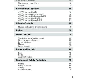
105
2005 Explorer Sport Trac (p27) Owners Guide (post-2002-fmt) USA (fus)
Seating and Safety Restraints
The BeltMinder娂 feature can be deactivated/activated by performing the following procedure: Before following the procedure, make sure that: • The parking brake is set • The gearshift is in P (Park) (automatic transmission) • The ignition switch is in the OFF position • The driver and passenger safety belt is unbuckled
To reduce the risk of injury, do not deactivate/activate the Belt Minder feature while driving the vehicle.
1. Turn the ignition switch to the RUN (or ON) position. (DO NOT START THE ENGINE) 2. Wait until the safety belt warning light turns off. (Approximately 1
minute) • Step 3 must be completed within 50 seconds after the safety beltwarning light turns off.
3. Buckle then unbuckle the safety belt on the driver’s side 9 times, ending in the unbuckled state. (Step 3 must be completed within 50
seconds after the safety belt warning light turns off.) • After Step 3, the restraint system warning light (airbag light) will beturned on for three seconds.
4. Within 10 seconds of the light turning on, buckle then unbuckle the safety belt once. • This will disable the BeltMinder娂 feature if it is currently enabled. As confirmation, the restraint system warning light will flash 4 times per second for 3 seconds. • This will enable the BeltMinder娂 feature if it is currently disabled. As confirmation, the restraint system warning light will flash 4 times per second for 3 seconds, followed by 3 seconds with the light off, then followed by the restraint system warning light flashing 4 times per second for 3 seconds again.
106
2005 Explorer Sport Trac (p27) Owners Guide (post-2002-fmt) USA (fus)
Seating and Safety Restraints
Safety belt extension assembly If the safety belt is too short when fully extended, there is an 8 inch (20 cm) safety belt extension assembly that can be added (part number 611C22). This assembly can be obtained from your dealer at no cost. Use only extensions manufactured by the same supplier as the safety belt. Manufacturer identification is located at the end of the webbing on the label. Also, use the safety belt extension only if the safety belt is too short for you when fully extended.
Do not use extensions to change the fit of the shoulder belt across the torso.
Safety belt maintenance Inspect the safety belt systems periodically to make sure they work properly and are not damaged (nicks, tears or cuts). Replace parts as necessary. All safety belt assemblies, including retractors, buckles, front seat belt buckle assemblies, buckle support assemblies (slide bar-if equipped), shoulder belt height adjusters (if equipped), shoulder belt guide on seatback (if equipped), child safety seat tether bracket assemblies (if equipped), LATCH child seat tether anchors and lower anchors (if equipped), and attaching hardware, should be inspected after a collision. Ford Motor Company recommends that all safety belt assemblies in use in vehicles involved in a collision be replaced. However, if the collision was minor and a qualified technician finds that the belts do not show damage and continue to operate properly, they do not need to be replaced. Safety belt assemblies not in use during a collision should also be inspected and replaced if either damage or improper operation is noted.
Failure to inspect and if necessary replace the safety belt assembly under the above conditions could result in severe
personal injuries in the event of a collision.
Refer to Interior in the Cleaning chapter.
107
2005 Explorer Sport Trac (p27) Owners Guide (post-2002-fmt) USA (fus)
Seating and Safety Restraints
AIRBAG SUPPLEMENTAL RESTRAINT SYSTEM (SRS)
Your vehicle is equipped with a crash sensing and diagnostic module which records information about the airbag and sensor systems. In the event of a collision this module may save information related to the collision including information about the airbag system and impact severity. This information will assist Ford Motor Company in servicing the vehicle and in helping to better understand real world collisions and further improve the safety of future vehicles. Important SRS precautions The SRS is designed to work with the safety belt to help protect the driver and right front passenger from certain upper body injuries. Airbags DO NOT inflate slowly; there is a risk of injury from a deploying airbag.
All occupants of the vehicle, including the driver, should always properly wear their safety belts, even when an air bag
supplemental restraint system (SRS) is provided.
108
2005 Explorer Sport Trac (p27) Owners Guide (post-2002-fmt) USA (fus)
Seating and Safety Restraints
Always transport children 12 years old and under in the back seat and always properly use appropriate child restraints.
National Highway Traffic Safety Administration (NHTSA) recommends a minimum distance of at least 10 inches (25 cm)
between an occupant’s chest and the airbag module.
Never place your arm over the air bag module as a deploying air bag can result in serious arm fractures or other injuries.
To properly position yourself away from the airbag: • Move your seat to the rear as far as you can while still reaching the • Recline the seat slightly one or two degrees from the upright position.
pedals comfortably.
Do not put anything on or over the air bag module. Placing objects on or over the air bag inflation area may cause those
objects to be propelled by the air bag into your face and torso causing serious injury.
Do not attempt to service, repair, or modify the airbag supplemental restraint systems or its fuses. See your Ford or
Lincoln/Mercury dealer.
Modifying or adding equipment to the front end of the vehicle (including frame, bumper, front end body structure and tow
hooks) may affect the performance of the airbag system, increasing the risk of injury. Do not modify the front end of the vehicle.
109
2005 Explorer Sport Trac (p27) Owners Guide (post-2002-fmt) USA (fus)
Seating and Safety Restraints
Children and airbags Children must always be properly restrained; accident statistics suggest that children are safer when properly restrained in the rear seating positions than in the front seating position. Failure to follow these instructions may increase the risk of injury in a collision.
Air bags can kill or injure a child in a child seat.
NEVER place a rear-facing child seat in front of an active air bag. If you must use a forward-facing child seat in the front seat, move the seat all the way back.
How does the airbag supplemental restraint system work? The airbag SRS is designed to activate when the vehicle sustains a longitudinal deceleration sufficient to cause the airbag sensors to close an electrical circuit that initiates airbag inflation. The fact that the airbags did not inflate in a collision does not mean that something is wrong with the system. Rather, it means the forces were not sufficient enough to cause activation. Front airbags are designed to inflate in frontal and near-frontal collisions, not rollover, side-impact, or rear-impacts unless the collision causes sufficient longitudinal deceleration.
110
2005 Explorer Sport Trac (p27) Owners Guide (post-2002-fmt) USA (fus)
Seating and Safety Restraints
The airbags inflate and deflate rapidly upon activation. After airbag deployment, it is normal to notice a smoke-like, powdery residue or smell the burnt propellant. This may consist of cornstarch, talcum powder or sodium compounds which may irritate the skin and eyes, but none of the residue is toxic. While the SRS is designed to help reduce serious injuries, contact with a deploying airbag may also cause abrasions, swelling or temporary hearing loss. Because airbags must inflate rapidly and with considerable force, there is the risk of death or serious injuries such as fractures, facial and eye injuries or internal injuries, particularly to occupants who are not properly restrained or are otherwise out of position at the time of airbag deployment. It is extremely important that occupants be properly restrained as far away from the airbag module as possible while maintaining vehicle control. The SRS consists of: • driver and passenger airbag modules (which include the inflators and • one or more impact and safing sensors • a readiness light and tone • a diagnostic module • and the electrical wiring which connects the components The RCM (restraints control module) monitors its own internal circuits and the supplemental airbag electrical system wiring (including the impact sensors, the system wiring, the airbag system readiness light, the airbag back up power and the airbag ignitors).
airbags)
Several air bag system components get hot after inflation. Do not touch them after inflation.
If the airbag has deployed, the airbag will not function again and must be replaced immediately. If the airbag is not replaced, the unrepaired area will increase the risk of injury in a collision.
111
2005 Explorer Sport Trac (p27) Owners Guide (post-2002-fmt) USA (fus)
Seating and Safety Restraints
flash or stay lit.
Determining if the system is operational The SRS uses a readiness light in the instrument cluster or a tone to indicate the status of the system. Refer to Airbag readiness section in the Instrument Cluster chapter. Routine maintenance of the airbag is not required. A difficulty with the system is indicated by one or more of the following: • The readiness light will either • The readiness light will not illuminate immediately after ignition is turned on.
periodically until the problem and/or light are repaired.
• A series of five beeps will be heard. The tone pattern will repeat If any of these things happen, even intermittently, have the SRS serviced at your dealership or by a qualified technician immediately. Unless serviced, the system may not function properly in the event of a collision. SAFETY CANOPY姟 SYSTEM (IF EQUIPPED)
Do not place objects or mount equipment on or
near the headliner at the siderail that may come into contact with a deploying Safety Canopy娂. Failure to follow these instructions may increase the risk of personal injury in the event of a collision.
Do not lean your head on the door. The Safety Canopy娂 could injure you as it deploys from the headliner.
Do not attempt to service, repair, or modify the Safety Canopy娂 system, its fuses, the A, B, or C pillar trim, or the headliner on a
vehicle containing a Safety Canopy娂. See your Ford or Lincoln Mercury dealer.
112
2005 Explorer Sport Trac (p27) Owners Guide (post-2002-fmt) USA (fus)
Seating and Safety Restraints
All occupants of the vehicle including the driver should always wear their safety belts even when an airbag SRS and Safety
Canopy娂 system is provided.
To reduce risk of injury, do not obstruct or place objects in the deployment path of the inflatable Safety Canopy娂.
How does the Safety Canopy姟 system work? The design and development of the Safety Canopy娂 system included recommended testing procedures that were developed by a group of automotive safety experts known as the Side Airbag Technical Working Group. These recommended testing procedures help reduce the risk of injuries related to the deployment of side airbags (including the Safety Canopy娂). The Safety Canopy娂 system consists of the following: • An inflatable nylon curtain with a gas generator concealed behind the headliner and above the doors (one on each side of vehicle). • A headliner designed to flex open • The same warning light, electronic control and diagnostic unit as used • Two crash sensors mounted in the b-pillars (one on each side of the • Two crash sensors located at the c-pillar (one on each side of the • Rollover sensor in the restraints control module (RCM).
above the side doors to allow Safety Canopy娂 deployment.
for the front airbags.
vehicle).
vehicle).
113
2005 Explorer Sport Trac (p27) Owners Guide (post-2002-fmt) USA (fus)
Seating and Safety Restraints
The Safety Canopy娂 system, in combination with seat belts, can help reduce the risk of severe injuries in the event of a significant side impact collision or rollover event. Children 12 years old and under should always be properly restrained in the rear seats. The Safety Canopy娂 will not interfere with children restrained using a properly installed child or booster seat because it is designed to inflate downward from the headliner above the doors along the side window opening. The Safety Canopy娂 system is designed to activate when the vehicle sustains lateral deceleration sufficient to cause the side crash sensor to close an electrical circuit that initiates Safety Canopy娂 inflation or when a certain likelihood of a rollover event is detected by the rollover sensor. The Safety Canopy娂 is mounted to roof side-rail sheet metal, behind the headliner, above the first and second row seats. In certain lateral collisions or rollover events, the Safety Canopy娂 system will be activated, regardless of which seats are occupied. The Safety Canopy娂 is designed to inflate between the side window area and occupants to further enhance protection provided in side impact collisions and rollover events. The fact that the Safety Canopy娂 did not activate in a collision does not mean that something is wrong with the system. Rather, it means the forces were not of the type sufficient to cause activation. The Safety Canopy娂 is designed to inflate in certain side impact collisions or rollover events, not in rear impact, frontal or near-frontal collisions, unless the collision causes sufficient lateral deceleration or rollover likelihood.
Several Safety Canopy娂 system components get hot after inflation. Do not touch them after inflation.
114
2005 Explorer Sport Trac (p27) Owners Guide (post-2002-fmt) USA (fus)
Seating and Safety Restraints
If the Safety Canopy娂 system has deployed, the Safety Canopy娂 will not function again unless replaced. The
Safety Canopy娂 system (including the A, B and C pillar trim) must be inspected and serviced by a qualified technician in accordance with the vehicle service manual. If the Safety Canopy娂 is not replaced, the unrepaired area will increase the risk of injury in a collision.
Determining if the system is operational The SRS uses a readiness light in the instrument cluster or a tone to indicate the condition of the system. Refer to the Airbag readiness section in the Instrument Cluster chapter. Routine maintenance of the airbag is not required. Any difficulty with the system is indicated by one or more of the following: • The readiness light (same light as for front airbag system) will either • The readiness light will not illuminate immediately after ignition is • A series of five beeps will be heard. The tone pattern will repeat
flash or stay lit.
turned on.
periodically until the problem and light are repaired.
If any of these things happen, even intermittently, have the SRS serviced at your dealership or by a qualified technician immediately. Unless serviced, the system may not function properly in the event of a collision or rollover event.
Disposal of airbags and airbag equipped vehicles (including pretensioners) See your local dealership or qualified technician. Airbags MUST BE disposed of by qualified personnel.
SAFETY RESTRAINTS FOR CHILDREN Read the following sections for directions on how to properly use safety restraints for children. Also see Air bag supplemental restraint system (SRS) in this chapter for special instructions about air bags.
115
2005 Explorer Sport Trac (p27) Owners Guide (post-2002-fmt) USA (fus)
Seating and Safety Restraints
Important child restraint precautions You are required by law to use safety restraints for children in the U.S. and Canada. If small children (generally children who are four years old or younger and who weigh 40 lb. [18 kg] or less) ride in your vehicle, you must put them in safety seats made especially for children. Many states require that children use approved booster seats until they are eight years old. Check your local and state or provincial laws for specific requirements regarding the safety of children in your vehicle. When possible, always place children under age 12 in the rear seat of your vehicle. Accident statistics suggest that children are safer when properly restrained in the rear seating positions than in the front seating position.
Never let a passenger hold a child on his or her lap while the vehicle is moving. The passenger cannot protect the child from
injury in a collision.
Always follow the instructions and warnings that come with any infant or child restraint you might use.
Children and safety belts If the child is the proper size, restrain the child in a safety seat. Children who are too large for child safety seats (as specified by your child safety seat manufacturer) should always wear safety belts. Follow all the important safety restraint and air bag precautions that apply to adult passengers in your vehicle.
Do not leave children, unreliable adults, or pets unattended in your vehicle.
To improve the fit of lap and shoulder belts on children who have outgrown child safety seats, Ford recommends use of a belt-positioning booster seat that is labeled as conforming to all applicable Federal motor vehicle safety standards. Belt-positioning booster seats raise the child and provide a shorter, firmer seating cushion that encourages safer seating posture and better fit of lap and shoulder belts on the child. A belt-positioning booster seat should be used if the shoulder belt rests in front of the child’s face or neck, or if the lap belt does not fit snugly on both thighs, or if the thighs are too short to let the child sit all the way back on the seat cushion when the lower legs hang over the edge of the seat cushion. You may wish to discuss the special needs of your child with your pediatrician.
116
2005 Explorer Sport Trac (p27) Owners Guide (post-2002-fmt) USA (fus)
Seating and Safety Restraints
Child booster seats Children outgrow a typical convertible or toddler seat when they weigh 40 lb. (18 kg) and are around 4 years of age. Although the lap/shoulder belt will provide some protection, these children are still too small for lap/shoulder belts to fit properly, which could increase the risk of serious injury. To improve the fit of both the lap and shoulder belt on children who have outgrown child safety seats, Ford Motor Company recommends use of a belt-positioning booster. Booster seats position a child so that safety belts fit better. They lift the child up so that the lap belt rests low across the hips and the knees bend comfortably. Booster seats also make the shoulder belt fit better and more comfortably for growing children. When children should use booster seats Children need to use booster seats from the time they outgrow the toddler seat until they are big enough for the vehicle seat and lap/shoulder belt to fit properly. Generally this is when they weigh about 80 lb. (36 kg) (about 8 to 12 years old). Booster seats should be used until you can answer YES to ALL of these questions: • Can the child sit all the way back against the vehicle seat back with knees bent comfortably at the edge of the seat without slouching?
• Does the lap belt rest low across the hips? • Is the shoulder belt centered on the shoulder and chest? • Can the child stay seated like this for the whole trip?
117
2005 Explorer Sport Trac (p27) Owners Guide (post-2002-fmt) USA (fus)
Seating and Safety Restraints
Types of booster seats There are two types of belt-positioning booster seats: • Those that are backless.
If your backless booster seat has a removable shield, remove the shield and use the lap/shoulder belt. If a seating position has a low seat back and no head restraint, a backless booster seat may place your child’s head (top of ear level) above the top of the seat. In this case, move the backless booster to another seating position with a higher seat back and lap/shoulder belts.
• Those with a high back.
If, with a backless booster seat, you cannot find a seating position that adequately supports your child’s head, a high back booster seat would be a better choice.
Both can be used in any vehicle in a seating position equipped with lap/shoulder belts if your child is over 40 lb. (18 kg). The shoulder belt should cross the chest, resting snugly on the center of the shoulder. The lap belt should rest low and snug across the hips, never up high across the stomach. If the booster seat slides on the vehicle seat, placing a rubberized mesh sold as shelf or carpet liner under the booster seat may improve this condition. The importance of shoulder belts Using a booster without a shoulder belt increases the risk of a child’s head hitting a hard surface in a collision. For this reason, you should never use a booster seat with a lap belt only. It is best to use a booster seat with lap/shoulder belts in the back seat- the safest place for children to ride.
118
2005 Explorer Sport Trac (p27) Owners Guide (post-2002-fmt) USA (fus)
Seating and Safety Restraints
Follow all instructions provided by the manufacturer of the booster seat.
Never put the shoulder belt under a child’s arm or behind the back because it eliminates the protection for the upper part of
the body and may increase the risk of injury or death in a collision.
Never use pillows, books, or towels to boost a child. They can slide around and increase the likelihood of injury or death in a
collision.
SAFETY SEATS FOR CHILDREN Child and infant or child safety seats Use a safety seat that is recommended for the size and weight of the child. Carefully follow all of the manufacturer’s instructions with the safety seat you put in your vehicle. If you do not install and use the safety seat properly, the child may be injured in a sudden stop or collision. When installing a child safety seat: • Review and follow the information presented in the Air Bag Supplemental Restraint System (SRS) section in this chapter. • Use the correct safety belt buckle for that seating position (the buckle closest to the direction the tongue is coming from).
• Insert the belt tongue into the proper buckle until you hear a snap and feel it latch. Make sure the tongue is securely fastened in the buckle. • Keep the buckle release button pointing up and away from the safety seat, with the tongue between the child seat and the release button, to prevent accidental unbuckling. • Place seat back in upright position. • Put the safety belt in the automatic locking mode. Refer to Automatic
locking mode (passenger side front and outboard rear seating positions) (if equipped) section in this chapter.
119
2005 Explorer Sport Trac (p27) Owners Guide (post-2002-fmt) USA (fus)
Seating and Safety Restraints • LATCH lower anchors are recommended for use by children up to 48
pounds (22 kg) in a child restraint. Top tether anchors can be used for children up to 60 pounds (27 kg) in a child restraint, and to provide upper torso restraint for children up to 80 pounds (36 kg ) using an upper torso harness and a belt-positioning booster.Ford recommends the use of a child safety seat having a top tether strap. Install the child safety seat in a seating position with LATCH and tether anchors. For more information on top tether straps and anchors, refer to Attaching safety seats with tether straps in this chapter. For more information of LATCH anchors refer to Attaching safety seats with LATCH (Lower Anchors and Tethers for Children) attachments in this chapter.
Carefully follow all of the manufacturer’s instructions included with the safety seat you put in your vehicle. If you do not install and use the safety seat properly, the child may be injured in a sudden stop or collision.
Installing child safety seats in combination lap and shoulder belt seating positions
Air bags can kill or injure a child in a child seat. NEVER place a rear-facing child seat in front of an active air bag. If you must
use a forward-facing child seat in the front seat, move the seat all the way back.
Children 12 and under should be properly restrained in the rear seat whenever possible.
120
2005 Explorer Sport Trac (p27) Owners Guide (post-2002-fmt) USA (fus)
Seating and Safety Restraints
1. Position the child safety seat in a seat with a combination lap and shoulder belt.
2. Pull down on the shoulder belt and then grasp the shoulder belt and lap belt together.
3. While holding the shoulder and lap belt portions together, route the tongue through the child seat according to the child seat manufacturer’s instructions. Be sure the belt webbing is not twisted.
121
2005 Explorer Sport Trac (p27) Owners Guide (post-2002-fmt) USA (fus)
Seating and Safety Restraints
4. Insert the belt tongue into the proper buckle (the buckle closest to the direction the tongue is coming from) for that seating position until you hear a snap and feel the latch engage. Make sure the tongue is latched securely by pulling on it.
5. To put the retractor in the automatic locking mode, grasp the shoulder portion of the belt and pull downward until all of the belt is extracted and a click is heard.
6. Allow the belt to retract. The belt will click as it retracts to indicate it is in the automatic locking mode. 7. Pull the lap belt portion across the child seat toward the buckle and pull up on the shoulder belt while pushing down with your knee on the child seat.
122
2005 Explorer Sport Trac (p27) Owners Guide (post-2002-fmt) USA (fus)
Seating and Safety Restraints
8. Allow the safety belt to retract to remove any slack in the belt. 9. Before placing the child in the seat, forcibly tilt the seat forward and back to make sure the seat is securely held in place. To check this, grab the seat at the belt path and attempt to move it side to side and forward and back. There should be no more than one inch of movement for proper installation. 10. Try to pull the belt out of the retractor to make sure the retractor is in the automatic locking mode (you should not be able to pull more belt out). If the retractor is not locked, unbuckle the belt and repeat Steps two through nine. Check to make sure the child seat is properly secured before each use.
Installing child safety seat in the second row center seating position with an automatic locking retractor lap belt 1. Place the child safety seat in the center seating position. 2. In a continuous motion, pull out enough webbing from the retractor to route the tongue through the child seat. 3. While holding the webbing to prevent it from retracting, route the webbing through the child seat according to the child seat manufacturer’s instructions. Be sure the belt webbing is not twisted. 4. Insert the tongue into the correct buckle for that seating position until you hear and feel the buckle engage. Make sure the buckle is latched securely by pulling on the webbing. 5. If you have not pulled out enough webbing to reach, allow the webbing to fully retract before attempting to pull it out again and repeat Steps 2 through 4. 6. Pull the webbing through the child seat toward the retractor while pushing down with your knee on the child seat. 7. Allow the safety belt to retract to remove any slack in the belt. It will make a clicking noise while doing this. 8. Before placing the child in the seat, forcibly move the seat forward and side-to-side to make sure the seat is securely held in place. 9. Check to make sure the child seat is properly secured before each use.
123
2005 Explorer Sport Trac (p27) Owners Guide (post-2002-fmt) USA (fus)
Seating and Safety Restraints
Attaching child safety seats with tether straps Most new forward-facing child safety seats include a tether strap which goes over the back of the seat and hooks to an anchoring point. Tether straps are available as an accessory for many older safety seats. Contact the manufacturer of your child seat for information about ordering a tether strap. The rear seats of your vehicle are equipped with built-in tether strap anchors located behind the seats as described below. The tether anchors in your vehicle are located behind sliding covers marked with the tether anchor symbol (shown with title). The tether strap anchors in your vehicle are in the following positions (shown from top view):
Attach the tether strap only to the appropriate tether
anchor as shown. The tether strap may not work properly if attached somewhere other than the correct tether anchor.
1. Position the child safety seat on the rear seat cushion. 2. Route the child safety seat tether strap over the back of the seat. For vehicles with adjustable head restraints, route the tether strap under the head restraint and between the head restraint posts, otherwise route the tether strap over the top of the seatback.
124
2005 Explorer Sport Trac (p27) Owners Guide (post-2002-fmt) USA (fus)
Seating and Safety Restraints
3. Locate the correct anchor for the selected rear seating position. To install a tethered child seat in the fixed left rear seat of Adrenalin vehicles, fold the right/center seat back down so that you can reach around the back of the left seat with your left hand to attach the tether hook onto the anchor.
• You may need to pull the seatback forward to access the tether
anchors. Make sure the seat is locked in the upright position before installing the child seat. Refer to the Folding Down The Rear Seats section in this chapter for information on how to operate the rear seats.
4. Slide open the tether anchor cover.
125
2005 Explorer Sport Trac (p27) Owners Guide (post-2002-fmt) USA (fus)
Seating and Safety Restraints
5. Clip the tether strap to the anchor and return the seat back to its locked position. For Adrenalin vehicles fixed left rear seat, clip the tether hook onto the anchor bar with the hook toward the rear of the vehicle.
If the tether strap is clipped incorrectly, the child safety seat may not be retained properly in the event of a collision.
6. Refer to the Installing child safety seats in combination lap and shoulder belt seating positions section of this chapter for further instructions to secure the child safety seat. 7. Tighten the child safety seat tether strap according to the manufacturer’s instructions. To unhook the tether strap, unfasten the seat belts securing the child seat and put some slack into the tether strap. Tip the seat back forward enough so that you can reach behind the seat and unhook the tether hook. For the Adrenalin Edition fixed left rear seat, fold the other seat back down so that you can reach around the side of the left seat back with your left hand to unclip the tether hook.
If the safety seat is not anchored properly, the risk of a child being injured in a collision greatly increases.
Attaching safety seats with LATCH (Lower Anchors and Tethers for Children) attachments for child seat anchors Some child safety seats have two rigid or webbing mounted attachments that connect to two anchors at certain seating positions in your vehicle. This type of child seat eliminates the need to use seat belts to attach the child seat. For forward-facing child seats, the tether strap must also be attached to the proper tether anchor. See Attaching safety seats with tether straps in this chapter.
126
2005 Explorer Sport Trac (p27) Owners Guide (post-2002-fmt) USA (fus)
Seating and Safety Restraints
Your vehicle has LATCH anchors for child seat installation at the following locations:
The LATCH anchors on both sides of the center of the rear seat are provided only for child seats at the outboard seats. These anchors are further apart than the pairs of lower anchors for child seat installation at other seats. DO NOT install a child seat with LATCH attachments (rigid or mounted on belt webbing) to the lower anchors on both sides of the center rear seat. If you install a child seat at the center rear position, use the vehicle belt and the top tether anchor.
Never attach two LATCH child safety seats to the same anchor. In a crash, one anchor may not be strong enough to hold two
child safety seat attachments and may break, causing serious injury or death.
The lower anchors for child seat installation are located at the rear section of the rear seat between the cushion and seat back. The LATCH anchors are below the locator symbols (if provided) on the seat back.
Follow the child seat manufacturer’s instructions to properly install a child seat with LATCH attachments.
Attach LATCH lower attachments of the child seat only to the anchors shown.
127
2005 Explorer Sport Trac (p27) Owners Guide (post-2002-fmt) USA (fus)
Seating and Safety Restraints
If you install a child seat with rigid LATCH attachments, do not tighten the tether strap enough to lift the child seat off the vehicle seat cushion when the child is seated in it. Keep the tether strap just snug without lifting the front of the child seat. Keeping the child seat just touching the vehicle seat gives the best protection in a severe crash. Each time you use the safety seat, check that the seat is properly attached to the lower anchors and tether anchor. Try to tilt the child seat from side to side. Also try to tug the seat forward. Check to see if the anchors hold the seat in place.
If the safety seat is not anchored properly, the risk of a child being injured in a crash greatly increases.
128
2005 Explorer Sport Trac (p27) Owners Guide (post-2002-fmt) USA (fus)
Tires, Wheels and Loading
NOTICE TO UTILITY VEHICLE AND TRUCK OWNERS Utility vehicles and trucks handle differently than passenger cars in the various driving conditions that are encountered on streets, highways and off-road. Utility vehicles and trucks are not designed for cornering at speeds as high as passenger cars any more than low-slung sports cars are designed to perform satisfactorily under off-road conditions.
Utility vehicles have a significantly higher rollover rate than other types of vehicles. To reduce the risk of serious injury or
death from a rollover or other crash you must: • Avoid sharp turns and abrupt maneuvers; • Drive at safe speeds for the conditions; • Keep tires properly inflated; • Never overload or improperly load your vehicle; and • Make sure every passenger is properly restrained.
In a rollover crash, an unbelted person is significantly more likely to die than a person wearing a seat belt. All occupants must
wear safety belts and children/infants must use appropriate restraints to minimize the risk of injury or ejection.
Study your Owner’s Guide and any supplements for specific information about equipment features, instructions for safe driving and additional precautions to reduce the risk of an accident or serious injury.
VEHICLE CHARACTERISTICS
4WD and AWD Systems (if equipped) A vehicle equipped with AWD or 4WD (when selected) has the ability to use all four wheels to power itself. This increases traction which may enable you to safely drive over terrain and road conditions that a conventional two-wheel drive vehicle cannot.
129
2005 Explorer Sport Trac (p27) Owners Guide (post-2002-fmt) USA (fus)
Tires, Wheels and Loading
Power is supplied to all four wheels through a transfer case or power transfer unit. 4WD vehicles allow you to select different drive modes as necessary. Information on transfer case operation and shifting procedures can be found in the Driving chapter. Information on transfer case maintenance can be found in the Maintenance and Specification chapter. You should become thoroughly familiar with this information before you operate your vehicle. On some 4WD models, the initial shift from two-wheel drive to 4WD while the vehicle is moving can cause a momentary clunk and ratcheting sound. These sounds are normal as the front drivetrain comes up to speed and is not cause for concern.
Do not become overconfident in the ability of 4WD and AWD vehicles. Although a 4WD or AWD vehicle may accelerate better
than two-wheel drive vehicle in low traction situations, it won’t stop any faster than two-wheel drive vehicles. Always drive at a safe speed.
How your vehicle differs from other vehicles SUV and trucks can differ from some other vehicles in a few noticeable ways. Your vehicle may be: • Higher – to allow higher load carrying capacity and to allow it to travel over rough terrain without getting hung up or damaging underbody components. • Shorter – to give it the capability
to approach inclines and drive over the crest of a hill without getting hung up or damaging underbody components. All other things held equal, a shorter wheelbase may make your vehicle quicker to respond to steering inputs than a vehicle with a longer wheelbase.
130
2005 Explorer Sport Trac (p27) Owners Guide (post-2002-fmt) USA (fus)
Tires, Wheels and Loading
• Narrower — to provide greater maneuverability in tight spaces, particularly in off-road use.
As a result of the above dimensional differences, SUV’s and trucks often will have a higher center of gravity and a greater difference in center of gravity between the loaded and unloaded condition. These differences that make your vehicle so versatile also make it handle differently than an ordinary passenger car.
INFORMATION ABOUT UNIFORM TIRE QUALITY GRADING New vehicles are fitted with tires that have a rating on them called Tire Quality Grades. The Quality grades can be found where applicable on the tire sidewall between tread shoulder and maximum section width. For example: • Treadwear 200 Traction AA Temperature A These Tire Quality Grades are determined by standards that the United States Department of Transportation has set. Tire Quality Grades apply to new pneumatic tires for use on passenger cars. They do not apply to deep tread, winter-type snow tires, space-saver or temporary use spare tires, tires with nominal rim diameters of 10 to 12 inches or limited production tires as defined in Title 49 Code of Federal Regulations Part 575.104(c)(2). U.S. Department of Transportation-Tire quality grades: The U.S. Department of Transportation requires Ford to give you the following information about tire grades exactly as the government has written it.
131
2005 Explorer Sport Trac (p27) Owners Guide (post-2002-fmt) USA (fus)
Tires, Wheels and Loading
Treadwear The treadwear grade is a comparative rating based on the wear rate of the tire when tested under controlled conditions on a specified government test course. For example, a tire graded 150 would wear one and one-half (1 1/2) times as well on the government course as a tire graded 100. The relative performance of tires depends upon the actual conditions of their use, however, and may depart significantly from the norm due to variations in driving habits, service practices, and differences in road characteristics and climate.
Traction AA A B C The traction grades, from highest to lowest are AA, A, B, and C. The grades represent the tire’s ability to stop on wet pavement as measured under controlled conditions on specified government test surfaces of asphalt and concrete. A tire marked C may have poor traction performance.
The traction grade assigned to this tire is based on straight-ahead braking traction tests, and does not include
acceleration, cornering, hydroplaning or peak traction characteristics.
Temperature A B C The temperature grades are A (the highest), B and C, representing the tire’s resistance to the generation of heat and its ability to dissipate heat when tested under controlled conditions on a specified indoor laboratory test wheel. Sustained high temperature can cause the material of the tire to degenerate and reduce tire life, and excessive temperature can lead to sudden tire failure. The grade C corresponds to a level of performance which all passenger car tires must meet under the Federal Motor Vehicle Safety Standard No. 109. Grades B and A represent higher levels of performance on the laboratory test wheel than the minimum required by law.
The temperature grade for this tire is established for a tire that is properly inflated and not overloaded. Excessive speed,
underinflation, or excessive loading, either separately or in combination, can cause heat buildup and possible tire failure.
TIRES Tires are designed to give many thousands of miles of service, but they must be maintained in order to get the maximum benefit from them.
132
2005 Explorer Sport Trac (p27) Owners Guide (post-2002-fmt) USA (fus)
Tires, Wheels and Loading
Glossary of tire terminology • Safety Compliance Certification Label: A label showing the OE (Original Equipment) tire sizes, recommended inflation pressure and the maximum weight the vehicle can carry. • Tire Identification Number (TIN): A number on the sidewall of
each tire providing information about the tire brand and manufacturing plant, tire size and date of manufacture.
• Inflation pressure: A measure of the amount of air in a tire. • Standard load: A class of P-metric or Metric tires designed to carry a maximum load at 35 psi [37 psi (2.5 bar) for Metric tires]. Increasing the inflation pressure beyond this pressure will not increase the tire’s load carrying capability.
• Extra load: A class of P-metric or Metric tires designed to carry a heavier maximum load at 41 psi [43 psi (2.9 bar) for Metric tires]. Increasing the inflation pressure beyond this pressure will not increase the tire’s load carrying capability.
• kPa: Kilopascal, a metric unit of air pressure. • PSI: Pounds per square inch, a standard unit of air pressure. • Cold inflation pressure: The tire pressure when the vehicle has been stationary and out of direct sunlight for an hour or more and prior to the vehicle being driven for 1 mile (1.6 km).
front door.
• Recommended inflation pressure: The cold inflation pressure found on the Safety Compliance Certification Label located on the B-Pillar or the edge of the driver’s door. • B-pillar: The structural member at the side of the vehicle behind the • Bead area of the tire: Area of the tire next to the rim. • Sidewall of the tire: Area between the bead area and the tread. • Tread area of the tire: Area of the perimeter of the tire that • Rim: The metal support (wheel) for a tire or a tire and tube assembly
contacts the road when mounted on the vehicle.
upon which the tire beads are seated.
INSPECTING AND INFLATING YOUR TIRES Safe operation of your vehicle requires that your tires are properly inflated. Remember that a tire can lose up to half of its air pressure without appearing flat.
133
2005 Explorer Sport Trac (p27) Owners Guide (post-2002-fmt) USA (fus)
Tires, Wheels and Loading
Every day before you drive, check your tires. If one looks lower than the others, use a tire gauge to check pressure of all tires and adjust if required. At least once a month and before long trips, inspect each tire and check the tire pressure with a tire gauge (including spare, if equipped). Inflate all tires to the inflation pressure recommended by Ford Motor Company. Inspecting your tires Periodically inspect the tire treads for uneven or excessive wear and remove stones, nails, glass or other objects that may be wedged in the tread grooves. Check for holes or cuts that may permit air leakage from the tire and make necessary repairs. Also inspect the tire sidewalls for cuts, bruises and other damage. If internal damage to the tire is suspected, have the tire demounted and inspected in case it needs to be repaired or replaced. For your safety, tires that are damaged should not be used because they are more likely to blow out or fail. Tires can be damaged during off-road use, so inspection after off-road use is also recommended. Inflating your tires Use a tire gauge to check the tire inflation pressure, including the spare (if equipped), at least monthly and before long trips. You are strongly urged to buy a reliable tire pressure gauge, as automatic service station gauges may be inaccurate. Ford recommends the use of a digital or dial type tire pressure gauge rather than a stick type tire pressure gauge. Use the recommended cold inflation pressure for optimum tire performance and wear. Under-inflation or over-inflation may cause uneven treadwear patterns.
Under-inflation is the most common cause of tire failures and may result in severe tire cracking, tread separation or ⬙blowout⬙,
with unexpected loss of vehicle control and increased risk of injury. Under-inflation increases sidewall flexing and rolling resistance, resulting in heat buildup and internal damage to the tire. It also may result in unnecessary tire stress, irregular wear, loss of vehicle control and accidents. A tire can lose up to half of its air pressure and not appear to be flat!
134
2005 Explorer Sport Trac (p27) Owners Guide (post-2002-fmt) USA (fus)
Tires, Wheels and Loading
Always inflate your tires to the Ford recommended inflation pressure even if it is less than the maximum inflation pressure information found on the tire. The Ford recommended tire inflation pressure is found on the Safety Compliance Certification Label which is located on the B-Pillar or the edge of the driver’s door. Failure to follow the tire pressure recommendations can cause uneven treadwear patterns and adversely affect the way your vehicle handles. Maximum Permissible Inflation Pressure is the tire manufactures’ maximum permissible pressure and/or the pressure at which the maximum load can be carried by the tire. This pressure is normally higher than the manufacturer’s recommended cold inflation pressure which can be found on either the Safety Compliance Certification Label which is located on the B-Pillar or the edge of the driver’s door. The cold inflation pressure should never be set lower than the recommended pressure on the Safety Compliance Certification Label. When weather temperature changes occur, tire inflation pressures also change. A 10° F (6° C) temperature drop can cause a corresponding drop of 1 psi (7 kPa) in inflation pressure. Check your tire pressures frequently and adjust them to the proper pressure which can be found on the Safety Compliance Certification Label. If you are checking tire pressure when the tire is hot, (i.e. driven more than 1 mile [1.6 km]), never “bleed” or reduce air pressure. The tires are hot from driving and it is normal for pressures to increase above recommended cold pressures. A hot tire at or below recommended cold inflation pressure could be significantly under-inflated. To check the pressure in your tire(s): 1. Make sure the tires are cool, meaning they are not hot from driving even a mile. Note: If you have to drive a distance to get air for your tire(s), check and record the tire pressure first and add the appropriate air pressure when you get to the pump. It is normal for tires to heat up and the air pressure inside to go up as you drive. Never “bleed” or reduce air pressure when tires are hot. 2. Remove the cap from the valve on one tire, then firmly press the tire gauge onto the valve and measure the pressure with the tire gauge. 3. Add enough air to reach the recommended air pressure Note: If you overfill the tire, release air by pushing on the metal stem in the center of the valve. Then recheck the pressure with your tire gauge. 4. Replace the valve cap.
135
2005 Explorer Sport Trac (p27) Owners Guide (post-2002-fmt) USA (fus)
Tires, Wheels and Loading
5. Repeat this procedure for each tire, including the spare. Note: Some spare tires require higher inflation pressure than the other tires. Check the Safety Compliance Certification Label on the B pillar or the edge of the driver’s door for the recommended spare tire pressure. 6. Visually inspect the tires to make sure there are no nails or other objects embedded that could poke a hole in the tire and cause an air leak. 7. Check the sidewalls to make sure there are no gouges, cuts or bulges.
TIRE REPLACEMENT REQUIREMENTS Your vehicle is equipped with tires designed to provide a safe ride and handling capability.
Only use replacement tires and wheels that are the same size and type (such as P-metric versus LT-metric or all-season versus
all-terrain) as those originally provided by Ford. Use of any tire or wheel not recommended by Ford can affect the safety and performance of your vehicle, which could result in an increased risk of loss of vehicle control, vehicle rollover, personal injury and death. Additionally the use of non-recommended tires and wheels could cause steering, suspension, axle or transfer case/power transfer unit failure. If you have questions regarding tire replacement, see an authorized Ford or Lincoln Mercury dealer.
Make sure all tires and wheels on the vehicle are of the same size, type, tread design, brand, load-carrying capacity and speed rating because it can affect the safety and performance of your vehicle, which could result in an increased risk of loss of vehicle control, vehicle rollover, personal injury and death. Important: Remember to replace the spare tire when you replace the road tires on your vehicle. Even if it has never been used, the spare tire should be replaced because tires degrade over time. Important: Remember to replace the wheel air valves when the road tires are replaced on your vehicle.
CHANGING A FLAT TIRE If you get a flat tire while driving: • do not brake heavily. • gradually decrease the vehicle’s speed. 136
2005 Explorer Sport Trac (p27) Owners Guide (post-2002-fmt) USA (fus)
Tires, Wheels and Loading
• hold the steering wheel firmly. • slowly move to a safe place on the side of the road. The use of tire sealants may damage your tires.
Dissimilar spare tire/wheel information
Failure to follow these guidelines could result in an increased risk of tire failure, loss of vehicle control, injury or death.
Your vehicle may be equipped with a dissimilar spare tire/wheel. A dissimilar spare tire/wheel is defined as a spare tire and/or wheel that is different in brand, size or appearance from the road tires and wheels. If you have a dissimilar spare tire/wheel, then it is intended for temporary use only. This means that if you need to use it, you should replace it as soon as possible with a road tire/wheel that is the same size and type as the road tires and wheels that were originally provided by Ford. If the dissimilar spare tire or wheel is damaged, it should be replaced rather than repaired. When driving with the dissimilar spare tire/wheel, do not: • Exceed 70 mph (113 km/h) • Use more than one dissimilar spare tire/wheel at a time • Use commercial car washing equipment • Use snow chains on the end of the vehicle with the dissimilar spare
tire/wheel
The usage of a dissimilar spare tire/wheel can lead to impairment of the following: • Handling, stability and braking performance • Comfort and noise • Ground clearance and parking at curbs • Winter weather driving capability • Wet weather driving capability • All-Wheel Driving Capability (if applicable) • Load Leveling Adjustment (if applicable)
137
2005 Explorer Sport Trac (p27) Owners Guide (post-2002-fmt) USA (fus)
Tires, Wheels and Loading
When driving with the dissimilar spare tire/wheel additional caution should be given to: • Towing a trailer • Driving vehicles equipped with a camper body • Driving vehicles with a load on the cargo rack Drive cautiously when using a dissimilar spare tire/wheel and seek service as soon as possible. Location of the spare tire and tools The spare tire and tools for your vehicle are stowed in the following locations:
Location
Under the vehicle, just in front of the rear bumper In the passenger side rear cab compartment behind the access door in trim panel
Tool
Spare tire
Jack, Jack handle, jack handle extension, wheel lug nut wrench
Removing the jack To remove the jack, turn the thumbwheel (1) counterclockwise, then remove the jack (2), lug wrench (3) and jack handles (4) from the bracket.
Installing the jack To install the jack, place the jack handles (4) in the clips, then replace the lug wrench (3). Note: The square hole fits over the peg (5) on the jack stowage bracket. Ensure that the lug wrench handle is seated under the nib at the base of the peg. Fully lower the jack (2) by turning the thumbwheel (1) clockwise, then install the jack (2) by placing the base of the jack onto the stands (6). Place the plastic clip that is attached to the lug nut wrench between the head of the jack and the head of the lug wrench. Turn the thumbwheel (1) clockwise to raise the jack between the stands (6) and the top of the lug wrench (3).
138
2005 Explorer Sport Trac (p27) Owners Guide (post-2002-fmt) USA (fus)
Tires, Wheels and Loading
Removing the spare tire 1. Assemble the jack handle with the spade end to the lug wrench as shown in the illustration. • To assemble, depress button and slide the pieces together. To disassemble, depress the button and pull the pieces apart.
2. Insert the jack handle into the opening just above the rear bumper. The handle will stop moving forward and resistance to turning will be felt when properly engaged. 3. Turn the handle counterclockwise until tire is lowered to the ground, and the cable is slack. Slide the tire rearward. 4. Remove the retainer from the center of the spare tire. Stowing the jack and tools 1. Install the jack handles into the clips. 2. Install the lug wrench ensuring that the square hole is over the peg on the bracket. Ensure that the lug wrench handle is seated below the nib at the base of the peg. 3. Install the jack on the bracket and place the plastic clip that is attached to the lug wrench between the head of the jack and the head of the lug wrench. Turn the thumbwheel clockwise to raise the jack between the stands and the top of the lug wrench.
139
2005 Explorer Sport Trac (p27) Owners Guide (post-2002-fmt) USA (fus)
Tires, Wheels and Loading
How to change a flat tire
When one of the front wheels is off the ground, the transmission alone will not prevent the vehicle from moving or slipping off the
jack, even if the vehicle is in P (Park) (automatic transmission) or R (Reverse) (manual transmission).
To help prevent the vehicle from moving when you change a tire, be sure the parking brake is set, then block (in both directions)
the wheel that is diagonally opposite (other side and end of the vehicle) to the tire being changed.
If the vehicle slips off the jack, you or someone else could be seriously injured.
Do not attempt to change a tire on the side of the vehicle close to moving traffic. Pull far enough off the road to avoid the
danger of being hit when operating the jack or changing the wheel.
Before changing the tire: 1. Park on a level surface. 2. Activate the hazard flashers. 3. Place the gearshift lever in P (Park) (automatic transmission) or R (Reverse) (manual transmission). 4. Set the parking brake. 5. Turn off the ignition. To change the tire: Note: Passengers should not remain in the vehicle when the vehicle is being jacked. 1. Block both the front and rear of the wheel diagonally opposite the flat tire. For example, if the right front tire is flat, block the left rear wheel.
2. Remove any wheel trim by inserting the flat end of the lug nut wrench under the wheel trim flange, then twisting the wrench to pry it off.
140
2005 Explorer Sport Trac (p27) Owners Guide (post-2002-fmt) USA (fus)
Tires, Wheels and Loading
3. Loosen, but do not remove, the wheel lug nuts by turning them one-half turn counterclockwise.
Slide the jack handle and jack handle extension together. Slide the jack handle assembly into the end of the lug nut wrench. To disconnect, depress the button and pull the pieces apart. 4. Position the jack properly and insert the jack handle into the opening in the thumbwheel at the base of the jack. Turn the handle clockwise until the tire is a maximum of 1 inch (25 mm) off the ground.
To lessen the risk of personal injury, do not put any part of your body under the vehicle while changing a tire. Do not start the engine when your vehicle is on the jack. The jack is only meant for changing the tire. • Front
141
2005 Explorer Sport Trac (p27) Owners Guide (post-2002-fmt) USA (fus)
Tires, Wheels and Loading • Rear
To lessen the risk of personal injury, do not put any part of your body under the vehicle while changing a tire. Do not start the engine when your vehicle is on the jack. The jack is only meant for changing the tire.
• Never use the differential as a
jacking point.
5. Remove the wheel lug nuts with the lug nut wrench. 6. Replace the flat tire with the spare tire, making sure the valve stem is facing outward. Reinstall the lug nuts (cone side in) until the wheel is snug against the hub. Do not fully tighten the lug nuts until the wheel has been lowered. 7. Lower the wheel by turning the jack handle counterclockwise.
142
2005 Explorer Sport Trac (p27) Owners Guide (post-2002-fmt) USA (fus)
Tires, Wheels and Loading
8. Remove the jack and fully tighten the lug nuts in the order shown. Refer to Wheel lug nut torque specifications later in this chapter for the proper lug nut torque specification. 9. Stow the flat tire. Refer to Stowing the spare tire. 10. Stow the jack and lug nut wrench. Make sure the jack is fastened so it does not rattle when you drive. 11. Unblock the wheels. Stowing the flat/spare tire Note: Failure to follow spare tire stowage instructions may result in failure of cable or loss of spare tire. 1. Lay the tire on the ground with the valve stem facing in the direction specified on the Tire Changing Instructions located with the jack hardware. 2. Slide the wheel partially under the vehicle and install the retainer through the wheel center. Pull on the cable to align the components at the end of the cable. 3. Turn the jack handle clockwise until the tire is raised to its stowed position underneath the vehicle. The effort to turn the jack handle increases significantly and the spare tire carrier ratchets or slips when the tire is raised to the maximum tightness. Tighten to the best of your ability, to the point where the ratchet/slip occurs, if possible. The spare tire carrier will not allow you to overtighten. If the spare tire carrier ratchets or slips with little effort, take the vehicle to your dealer for assistance at your earliest convenience. 4. Check that the tire lies flat against the frame and is properly tightened. Try to push or pull, then turn the tire to be sure it will not move. Loosen and retighten, if necessary. Failure to properly stow the spare tire may result in failure of the winch cable and loss of the tire. 5. Repeat this tightness check procedure when servicing the spare tire pressure (every six months, as per your scheduled maintenance information), or at any time that the spare tire is disturbed through service of other components. 6. If removed, install the spare tire lock (if equipped) into the bumper drive tube with the spare tire lock key (if equipped) and jack handle.
143
2005 Explorer Sport Trac (p27) Owners Guide (post-2002-fmt) USA (fus)
Tires, Wheels and Loading
WHEEL LUG NUT TORQUE SPECIFICATIONS Retighten the lug nuts to the specified torque at 50–100 miles (80–160 km) after any wheel disturbance (rotation, flat tire, wheel removal, etc.).
Wheel lug nut torque*
Lug nut socket size/Bolt size Lug nut socket size: 3⁄4” (19 mm) hex Bolt size: 1⁄2 x 20
* Torque specifications are for nut and bolt threads free of dirt and rust. Use only Ford recommended replacement fasteners.N•m 135
lb.ft. 100
When a wheel is installed, always remove any corrosion, dirt and foreign materials present on the mounting surfaces of the wheel and the surface of the front disc brake hub and rotor that contacts the wheel. Installing wheels without correct metal-to-metal contact at the wheel mounting surfaces can cause the wheel nuts to loosen and the wheel to come off while the vehicle is in motion, resulting in loss of control.
Note: If there is corrosion on the area where the wheel contacts the hub, apply a thin film of grease or anti-seize compound on that area.
INFORMATION CONTAINED ON THE TIRE SIDEWALL Federal law requires tire manufacturers to place standardized information on the sidewall of all tires. This information identifies and describes the fundamental characteristics of the tire and also provides a U.S. DOT Tire Identification Number for safety standard certification and in case of a recall.
144
2005 Explorer Sport Trac (p27) Owners Guide (post-2002-fmt) USA (fus)
Tires, Wheels and Loading
Information on “P” type tires P215/65R15 95H is an example of a tire size, load index and speed rating. The definitions of these items are listed below. (Note that the tire size, load index and speed rating for your vehicle may be different from this example.) 1. P: Indicates a tire, designated by the Tire and Rim Association (T&RA), that may be used for service on cars, SUVs, minivans and light trucks. Note: If your tire size does not begin with a letter this may mean it is designated by either ETRTO (European Tire and Rim Technical Organization) or JATMA (Japan Tire Manufacturing Association). 2. 215: Indicates the nominal width of the tire in millimeters from sidewall edge to sidewall edge. In general, the larger the number, the wider the tire. 3. 65: Indicates the aspect ratio which gives the tire’s ratio of height to width. 4. R: Indicates a “radial” type tire. 5. 15: Indicates the wheel or rim diameter in inches. If you change your wheel size, you will have to purchase new tires to match the new wheel diameter. 6. 95: Indicates the tire’s load index. It is an index that relates to how much weight a tire can carry. You may find this information in your Owner’s Guide. If not, contact a local tire dealer. Note: You may not find this information on all tires because it is not required by federal law. 7. H: Indicates the tire’s speed rating. The speed rating denotes the speed at which a tire is designed to be driven for extended periods of time under a standard condition of load and inflation pressure. The tires on your vehicle may operate at different conditions for load and inflation pressure. These speed ratings may need to be adjusted for the difference in conditions. The ratings range from 81 mph (130 km/h) to 186 mph (299 km/h). These ratings are listed in the following chart.
145
2005 Explorer Sport Trac (p27) Owners Guide (post-2002-fmt) USA (fus)
Tires, Wheels and Loading
Note: You may not find this information on all tires because it is not required by federal law.
Letter rating
Speed rating - mph (km/h)
81 mph (130 km/h) 87 mph (140 km/h) 99 mph (159 km/h) 106 mph (171 km/h) 112 mph (180 km/h) 118 mph (190 km/h) 124 mph (200 km/h) 130 mph (210 km/h) 149 mph (240 km/h) 168 mph (270 km/h) 186 mph (299 km/h) Note: For tires with a maximum speed capability over 149 mph (240 km/h), tire manufacturers sometimes use the letters ZR. For those with a maximum speed capability over 186 mph (299 km/h), tire manufacturers always use the letters ZR. 8. U.S. DOT Tire Identification Number (TIN): This begins with the letters “DOT” and indicates that the tire meets all federal standards. The next two numbers or letters are the plant code designating where it was manufactured, the next two are the tire size code and the last four numbers represent the week and year the tire was built. For example, the numbers 317 mean the 31st week of 1997. After 2000 the numbers go to four digits. For example, 2501 means the 25th week of 2001. The numbers in between are identification codes used for traceability. This information is used to contact customers if a tire defect requires a recall. 9. M+S or M/S: Mud and Snow, or AT: All Terrain, or AS: All Season. 10. Tire Ply Composition and Material Used: Indicates the number of plies or the number of layers of rubber-coated fabric in the tire tread and sidewall. Tire manufacturers also must indicate the ply materials in the tire and the sidewall, which include steel, nylon, polyester, and others. 11. Maximum Load: Indicates the maximum load in kilograms and pounds that can be carried by the tire. Refer to the Safety Compliance Certification Label, which is located on the B-Pillar or the edge of the driver’s door, for the correct tire pressure for your vehicle.
146
2005 Explorer Sport Trac (p27) Owners Guide (post-2002-fmt) USA (fus)
Tires, Wheels and Loading
12. Treadwear, Traction and Temperature Grades • Treadwear: The treadwear grade is a comparative rating based on the
wear rate of the tire when tested under controlled conditions on a specified government test course. For example, a tire graded 150
would wear one and one-half (11⁄2) times as well on the government course as a tire graded 100. • Traction: The traction grades, from highest to lowest are AA, A, B,and C. The grades represent the tire’s ability to stop on wet pavement as measured under controlled conditions on specified government test surfaces of asphalt and concrete. A tire marked C may have poor traction performance.
• Temperature: The temperature grades are A (the highest), B and C, representing the tire’s resistance to the generation of heat and its ability to dissipate heat when tested under controlled conditions on a specified indoor laboratory test wheel.
13. Maximum Permissible Inflation Pressure: Indicates the tire manufacturers’ maximum permissible pressure and/or the pressure at which the maximum load can be carried by the tire. This pressure is normally higher than the manufacturer’s recommended cold inflation pressure which can be found on either the Safety Compliance Certification Label which is located on the B-Pillar or the edge of the driver’s door. The cold inflation pressure should never be set lower than the recommended pressure on the vehicle label. The tire suppliers may have additional markings, notes or warnings such as standard load, radial tubeless, etc.
147
2005 Explorer Sport Trac (p27) Owners Guide (post-2002-fmt) USA (fus)
Tires, Wheels and Loading
Additional information contained on the tire sidewall for “LT” type tires “LT” type tires have some additional information beyond those of “P” type tires; these differences are described below: 1. LT: Indicates a tire, designated by the Tire and Rim Association (T&RA), that is intended for service on light trucks. 2. Load Range/Load Inflation Limits: Indicates the tire’s load-carrying capabilities and its inflation limits. 3. Maximum Load Dual lb. (kg) at psi (kPa) cold: Indicates the maximum load and tire pressure when the tire is used as a dual; defined as four tires on the rear axle (a total of six or more tires on the vehicle). 4. Maximum Load Single lb. (kg) at psi (kPa) cold: Indicates the maximum load and tire pressure when the tire is used as a single; defined as two tires (total) on the rear axle.
148
2005 Explorer Sport Trac (p27) Owners Guide (post-2002-fmt) USA (fus)
Tires, Wheels and Loading
Information on “T” type tires “T” type tires have some additional information beyond those of “P” type tires; these differences are described below: T145/80D16 is an example of a tire size. Note: The temporary tire size for your vehicle may be different from this example. 1. T: Indicates a type of tire, designated by the Tire and Rim Association (T&RA), that is intended for temporary service on cars, SUVs, minivans and light trucks. 2. 145: Indicates the nominal width of the tire in millimeters from sidewall edge to sidewall edge. In general, the larger the number, the wider the tire. 3. 80: Indicates the aspect ratio which gives the tire’s ratio of height to width. Numbers of 70 or lower indicate a short sidewall. 4. D: Indicates a “diagonal” type tire. R: Indicates a “radial” type tire. 5. 16: Indicates the wheel or rim diameter in inches. If you change your wheel size, you will have to purchase new tires to match the new wheel diameter.
Location of the Safety Compliance Certification Label You will find a Safety Compliance Certification Label containing tire inflation pressure by tire size and other important information located on the B-Pillar or the edge of the driver’s door. Refer to the payload description and graphic in the Vehicle loading — with and without a trailer section.
149
2005 Explorer Sport Trac (p27) Owners Guide (post-2002-fmt) USA (fus)
Tires, Wheels and Loading
TIRE CARE Improper or inadequate vehicle maintenance can also cause tires to wear abnormally. Here are some of the important maintenance items: Tire wear Measure and inspect the tire tread on all your tires periodically. Advanced and unusual tire wear can reduce the ability of tread to grip the road in adverse (wet, snowy, etc.) conditions. Visually check your tires for uneven wear, looking for high and low areas or unusually smooth areas. Also check for signs of tire damage. When the tread is worn down to 1/16th of an inch (2 mm), tires must be replaced to prevent your vehicle from skidding and hydroplaning. Built-in treadwear indicators, or “wear bars”, which look like narrow strips of smooth rubber across the tread will appear on the tire when the tread is worn down to 1/16th of an inch (2 mm). When the tire tread wears down to the same height as these “wear bars”, the tire is worn out and should be replaced. Inspect your tires frequently for any of the following conditions and replace them if one or more of the following conditions exist: • Fabric showing through the tire • Bulges in the tread or sidewalls • Cracks or cuts on the sidewalls • Cracks in the tread groove • Impact damage resulting from use • Separation in the tread • Separation in the sidewall • Severe abrasion on the sidewall If your vehicle has a leak in the exhaust system, a road tire or the spare tire may be exposed to hot exhaust temperatures requiring the tire to be replaced.
rubber
150
2005 Explorer Sport Trac (p27) Owners Guide (post-2002-fmt) USA (fus)
Tires, Wheels and Loading
Safety practices Driving habits have a great deal to do with your tire mileage and safety. • Observe posted speed limits • Avoid fast starts, stops and turns • Avoid potholes and objects on the road • Do not run over curbs or hit the tire against a curb when parking
If your vehicle is stuck in snow, mud, sand, etc., do not rapidly spin the tires; spinning the tires can tear the tire and cause an
explosion. A tire can explode in as little as three to five seconds.
Never spin the tires in excess of the 35 mph (55 km/h) point indicated on the speedometer.
Highway hazards No matter how carefully you drive there’s always the possibility that you may eventually have a flat tire on the highway. Drive slowly to the closest safe area out of traffic. This may further damage the flat tire, but your safety is more important. If you feel a sudden vibration or ride disturbance while driving, or you suspect your tire or vehicle has been damaged, immediately reduce your speed. Drive with caution until you can safely pull off the road. Stop and inspect the tires for damage. If a tire is under-inflated or damaged, deflate it, remove wheel and replace it with your spare tire and wheel. If you cannot detect a cause, have the vehicle towed to the nearest repair facility or tire dealer to have the vehicle inspected.
Tire and wheel alignment A bad jolt from hitting a curb or pothole can cause the front end of your vehicle to become misaligned or cause damage to your tires. If your vehicle seems to pull to one side when you’re driving, the wheels may be out of alignment. Have a qualified technician at a Ford or Lincoln Mercury dealer check the wheel alignment periodically. Wheel misalignment in the front or the rear can cause uneven and rapid treadwear of your tires and should be corrected by a qualified technician at a Ford or Lincoln Mercury dealer. Front wheel drive (FWD) vehicles and those with an independent rear suspension (if equipped) may require alignment of all four wheels.
151
2005 Explorer Sport Trac (p27) Owners Guide (post-2002-fmt) USA (fus)
Tires, Wheels and Loading
The tires should also be balanced periodically. An unbalanced tire and wheel assembly may result in irregular tire wear.
Tire rotation Rotating your tires at the recommended interval (as indicated in the scheduled maintenance information that comes with your vehicle) will help your tires wear more evenly, providing better tire performance and longer tire life. Unless otherwise specified, rotate the tires approximately every 5,000 miles (8,000 km). • Front Wheel Drive (FWD)
vehicles (front tires at top of diagram)
152
2005 Explorer Sport Trac (p27) Owners Guide (post-2002-fmt) USA (fus)
Tires, Wheels and Loading
• Rear Wheel Drive (RWD) vehicles/Four Wheel Drive (4WD)/ All Wheel Drive (AWD) vehicles (front tires at top of diagram)
Sometimes irregular tire wear can be corrected by rotating the tires. Note: If your tires show uneven wear ask a qualified technician at a Ford or Lincoln Mercury dealership to check for and correct any wheel misalignment, tire imbalance or mechanical problem involved before tire rotation. Note: Your vehicle may be equipped with a dissimilar spare tire/wheel. A dissimilar spare tire/wheel is defined as a spare tire and/or wheel that is different in brand, size or appearance from the road tires and wheels. If you have a dissimilar spare tire/wheel it is intended for temporary use only and should not be used in a tire rotation. Note: After having your tires rotated, inflation pressure must be checked and adjusted to the vehicle requirements.
153
2005 Explorer Sport Trac (p27) Owners Guide (post-2002-fmt) USA (fus)
Tires, Wheels and Loading
SNOW TIRES AND TRACTION DEVICES
Snow tires must be the same size and grade as the original tires.
Your tires have all-weather treads to provide traction in the rain and snow. In some climate, using snow tires or traction devices may be necessary. Ford Motor Company offers tire cables as a Ford approved accessory and recommends use of these or SAE class “S” cables. See your dealer for more information. Follow these guidelines: • Do not use tire cables or chains with P255/70R16 size tires. • Cables or chains should only be used on the rear wheels. • If you need to use chains, it is recommended that steel wheels (of the
same size and specification) be used, as chains may chip aluminum wheels. • Install cables or chains securely, verifying that they do not touch any wiring, brake lines or fuel lines. • Avoid overloading your vehicle. • Do not use cables or chains on dry roads. • Do not exceed 30 mph (48 km/h). • Drive cautiously. Remove the cables or chains when they are no longer needed.
VEHICLE LOADING – WITH AND WITHOUT A TRAILER This section will guide you in the proper loading of your vehicle and/or trailer, to keep your loaded vehicle weight within its design rating capability, with or without a trailer. Properly loading your vehicle will provide maximum return of vehicle design performance. Before loading your vehicle, familiarize yourself with the following terms for determining your vehicle’s weight ratings, with or without a trailer, from the vehicle’s Safety Compliance Certification Label: Base Curb Weight – is the weight of the vehicle including a full tank of fuel and all standard equipment. It does not include passengers, cargo, or optional equipment. Vehicle Curb Weight – is the weight of your new vehicle when you picked it up from your dealer plus any aftermarket equipment.
154
2005 Explorer Sport Trac (p27) Owners Guide (post-2002-fmt) USA (fus)
Tires, Wheels and Loading
Payload – is the combined weight of cargo and passengers that the vehicle is carrying. The maximum payload for your vehicle can be found on the Safety Compliance Certification Label on the B-Pillar or the edge of the driver’s door. Look for “THE COMBINED WEIGHT OF OCCUPANTS AND CARGO SHOULD NEVER EXCEED XXX kg OR XXX lb.” for maximum payload. The payload listed on the Safety Compliance Certification Label is the maximum payload for the vehicle as built by the assembly plant. If any aftermarket or dealer installed equipment has been installed on the vehicle, the weight of the equipment must be subtracted from the payload listed on the Safety Compliance Certification Label in order to determine the new payload.
The appropriate loading capacity of your vehicle can be limited either by volume capacity (how much space is available) or by payload capacity (how much weight the vehicle should carry). Once you have reached the maximum payload of your vehicle, do not add more cargo, even if there is space available. Overloading or improperly loading your vehicle can contribute to loss of vehicle control and vehicle rollover.
155
2005 Explorer Sport Trac (p27) Owners Guide (post-2002-fmt) USA (fus)
Tires, Wheels and Loading
Example only:
Cargo Weight – includes all weight added to the Base Curb Weight, including cargo and optional equipment. When towing, trailer tongue load or king pin weight is also part of cargo weight.
156
2005 Explorer Sport Trac (p27) Owners Guide (post-2002-fmt) USA (fus)
Tires, Wheels and Loading
GAW (Gross Axle Weight) – is the total weight placed on each axle (front and rear) – including vehicle curb weight and all payload. GAWR (Gross Axle Weight Rating) – is the maximum allowable weight that can be carried by a single axle (front or rear). These numbers are shown on the Safety Compliance Certification Label located on the B-Pillar or the edge of the driver’s door. The total load on each axle must never exceed its GAWR.
Exceeding the Safety Compliance Certification Label axle weight rating limits could result in substandard vehicle handling or
performance, engine, transmission and/or structural damage, serious damage to the vehicle, loss of control and personal injury.
Note: For trailer towing information refer to Trailer towing found in this chapter or the RV and Trailer Towing Guide provided by your dealership.
GVW (Gross Vehicle Weight) – is the Vehicle Curb Weight + cargo + passengers.
157
2005 Explorer Sport Trac (p27) Owners Guide (post-2002-fmt) USA (fus)
Tires, Wheels and Loading
GVWR (Gross Vehicle Weight Rating) – is the maximum allowable weight of the fully loaded vehicle (including all options, equipment, passengers and cargo). The GVWR is shown on the Safety Compliance Certification Label located on the B-Pillar or the edge of the driver’s door. The GVW must never exceed the GVWR.
Exceeding the Safety Compliance Certification Label vehicle weight rating limits could result in substandard vehicle handling or performance, engine, transmission and/or structural damage, serious damage to the vehicle, loss of control and personal injury.
GCW (Gross Combined Weight) – is the weight of the loaded vehicle (GVW) plus the weight of the fully loaded trailer. GCWR (Gross Combined Weight Rating) – is the maximum allowable weight of the vehicle and the loaded trailer – including all cargo and passengers – that the vehicle can handle without risking damage. (Important: The towing vehicle’s braking system is rated for operation at GVWR, not at GCWR.) Separate functional brakes should be used for safe control of towed vehicles and for trailers where the GCW of the towing vehicle plus the trailer exceed the GVWR of the towing vehicle. The GCW must never exceed the GCWR. Maximum Loaded Trailer Weight – is the highest possible weight of a fully loaded trailer the vehicle can tow. It assumes a vehicle with only
158
2005 Explorer Sport Trac (p27) Owners Guide (post-2002-fmt) USA (fus)
Tires, Wheels and Loading
mandatory options, no cargo (internal or external), a tongue load of 10–15% (conventional trailer) or king pin weight of 15–25% (fifth wheel trailer), and driver only (150 lb. [68 kg]). Consult your dealership (or the RV and Trailer Towing Guide provided by your dealership) for more detailed information. Tongue Load or Fifth Wheel King Pin Weight – refers to the amount of the weight that a trailer pushes down on a trailer hitch. Examples: For a 5,000 lb. (2,268 kg) conventional trailer, multiply 5,000
by 0.10 and 0.15 to obtain a proper tongue load range of 500 to 750 lb. (227 to 340 kg). For an 11,500 lb. (5,216 kg) fifth wheel trailer, multiply by 0.15 and 0.25 to obtain a proper king pin load range of 1,725 to 2,875
lb. (782 to 1,304 kg)Do not exceed the GVWR or the GAWR specified on the Safety Compliance Certification Label.
Do not use replacement tires with lower load carrying capacities than the originals because they may lower the vehicle’s GVWR and GAWR limitations. Replacement tires with a higher limit than the originals do not increase the GVWR and GAWR limitations.
Exceeding any vehicle weight rating limitation could result in serious damage to the vehicle and/or personal injury.
Steps for determining the correct load limit: 1. Locate the statement “The combined weight of occupants and cargo should never exceed XXX kg or XXX lbs.” on your vehicle’s placard. 2. Determine the combined weight of the driver and passengers that will be riding in your vehicle. 3. Subtract the combined weight of the driver and passengers from XXX kg or XXX lbs. 4. The resulting figure equals the available amount of cargo and luggage load capacity. For example, if the “XXX” amount equals 1,400 lbs. and there will be five 150 lb. passengers in your vehicle, the amount of available cargo and luggage load capacity is 650 lbs. (1400–750 (5 x 150) = 650 lb.). In metric units (635–340 (5 x 68) = 295 kg.) 5. Determine the combined weight of luggage and cargo being loaded on the vehicle. That weight may not safely exceed the available cargo and luggage load capacity calculated in Step 4.
159
2005 Explorer Sport Trac (p27) Owners Guide (post-2002-fmt) USA (fus)
Tires, Wheels and Loading
6. If your vehicle will be towing a trailer, load from your trailer will be transferred to your vehicle. Consult this manual to determine how this reduces the available cargo and luggage load capacity of your vehicle. The following gives you a few examples on how to calculate the available amount of cargo and luggage load capacity: • Another example for your vehicle with 1400 lb. (635 kg) of cargo and luggage capacity. You decide to go golfing. Is there enough load capacity to carry you, 4 of your friends and all the golf bags? You and four friends average 220 lb. (99 kg) each and the golf bags weigh approximately 30 lb. (13.5 kg) each. The calculation would be: 1400 – (5 x 220) – (5 x 30) = 1400 – 1100 – 150 = 150 lb. Yes, you have enough load capacity in your vehicle to transport four friends and your golf bags. In metric units, the calculation would be: 635 kg — (5
x 99 kg) — (5 x 13.5 kg) = 635 — 495 — 67.5 = 72.5 kg. • A final example for your vehicle with 1400 lb. (635 kg) of cargo and luggage capacity. You and one of your friends decide to pick up cement from the local home improvement store to finish that patio you have been planning for the past 2 years. Measuring the inside of the vehicle with the rear seat folded down, you have room for 12-100
lb. (45 kg) bags of cement. Do you have enough load capacity to transport the cement to your home? If you and your friend each weigh 220 lb. (99 kg), the calculation would be: 1400 – (2 x 220) – (12 x 100) = 1400 – 440 – 1200 = – 240 lb. No, you do not have enough cargo capacity to carry that much weight. In metric units, the calculation would be: 635 kg — (2 x 99 kg) — (12 x 45 kg) = 635 — 198 — 540 = —103 kg. You will need to reduce the load weight by at least 240 lb. (104 kg). If you remove 3-100 lb. (45 kg) cement bags, then the load calculation would be: 1400 – (2 x 220) – (9 x 100) = 1400 – 440 – 900 = 60 lb. Now you have the load capacity to transport the cement and your friend home. . In metric units, the calculation would be: 635 kg — (2 x 99 kg) — (9
x 45 kg) = 635 — 198 — 405 = 32 kg.The above calculations also assume that the loads are positioned in your vehicle in a manner that does not overload the Front or the Rear Gross Axle Weight Rating specified for your vehicle on the Safety Compliance Certification Label found on the edge of the driver’s door.
160
2005 Explorer Sport Trac (p27) Owners Guide (post-2002-fmt) USA (fus)
Tires, Wheels and Loading
Special loading instructions for owners of pickup trucks and utility-type vehicles
For important information regarding safe operation of this type of vehicle, see the Preparing to drive your vehicle section in
the Driving chapter of this Owner’s Guide.
Loaded vehicles may handle differently than unloaded vehicles. Extra precautions, such as slower speeds and increased stopping
distance, should be taken when driving a heavily loaded vehicle.
Your vehicle can haul more cargo and people than most passenger cars. Depending upon the type and placement of the load, hauling cargo and people may raise the center of gravity of the vehicle.
Calculating the load your vehicle can carry/tow 1. Use the appropriate maximum GCWR chart (in the Trailer towing section in this chapter) for your type of engine and rear axle ratio. 2. Weigh your vehicle without cargo. To obtain correct weights, take your vehicle to a shipping company or an inspection station for trucks. 3. Subtract your loaded weight from the maximum GCWR in the chart. This is the maximum trailer weight your vehicle can tow. It must be below the maximum trailer weight shown in the chart.
TRAILER TOWING Trailer towing with your vehicle may require the use of a trailer tow option package. Trailer towing puts additional loads on your vehicle’s engine, transmission, axle, brakes, tires, and suspension. For your safety and to maximize vehicle performance, be sure to use the proper equipment while towing. Follow these guidelines to ensure safe towing procedure: • Stay within your vehicle’s load limits. • Thoroughly prepare your vehicle for towing. Refer to Preparing to • Use extra caution when driving while trailer towing. Refer to Driving • Service your vehicle more frequently if you tow a trailer. Refer to the
while you tow in this chapter.
tow in this chapter.
severe duty schedule in the scheduled maintenance guide.
161
2005 Explorer Sport Trac (p27) Owners Guide (post-2002-fmt) USA (fus)
Tires, Wheels and Loading • Do not tow a trailer until your vehicle has been driven at least 500
• Refer to the instructions included with towing accessories for themiles (800 km).
proper installation and adjustment specifications.
Do not exceed the maximum loads listed on the Safety Compliance Certification label. For load specification terms found on the label, refer to Vehicle loading in this chapter. Remember to figure in the tongue load of your loaded vehicle when figuring the total vehicle weight.
4x2
GCWR (Gross Combined Weight Rating)/Trailer weights Engine
Axle ratio
Maximum GCWR - lb. (kg)
Trailer Weight Range - lb. (kg) 0-Maximum 0–5260 (0-2386)
All
9600 (4354)
4.0L SOHC Notes: For high altitude operation, reduce GCW by 2% per 1,000 ft. (300 meters) elevation. For definition of terms and instructions on calculating your vehicle’s load, refer to Vehicle loading in this chapter. Maximum trailer weights shown. The combined weight of the completed towing vehicle and the loaded trailer must not exceed the GCWR.
GCWR (Gross Combined Weight Rating)/Trailer Weights Engine
Axle ratio
4x4
Maximum GCWR - lb. (kg)
Trailer Weight Range (0-Maximum) - lb. (kg) 0–5040 (0-2286)
All
9600 (4354)
4.0L SOHC Notes: For high altitude operation, reduce GCW by 2% per 1,000 ft. (300 meters) elevation. For definition of terms and instructions on calculating your vehicle’s load, refer to Vehicle loading in this chapter. Maximum trailer weights shown. The combined weight of the completed towing vehicle and the loaded trailer must not exceed the GCWR.
162
2005 Explorer Sport Trac (p27) Owners Guide (post-2002-fmt) USA (fus)
Tires, Wheels and Loading
Do not exceed the GVWR or the GAWR specified on the certification label.
Towing trailers beyond the maximum recommended gross trailer weight exceeds the limit of the vehicle and could result in
engine damage, transmission damage, structural damage, loss of vehicle control, vehicle rollover and personal injury.
Preparing to tow Use the proper equipment for towing a trailer and make sure it is properly attached to your vehicle. See your dealer or a reliable trailer dealer if you require assistance.
Hitches Do not use hitches that clamp onto the vehicle bumper. Use a weight-carrying or weight distributing hitch; a weight-distributing hitch is required for trailers over 3,500 lb. (1,588 kg). For proper handling, tongue weight must meet these requirements: • For trailers up to 2,000 lb. (907 kg), do not exceed 200 lb. (91 kg). • For trailers over 2,000 lb. (907 kg), use 10-15% of trailer weight. • For Class II receiver hitches, do not exceed tongue weight of 350 lb. (159 kg). For class III/IV receiver, do not exceed tongue weight of 500
lb. (227 kg) (weight carrying); 770 lb. (349 kg) (weight distributing).For additional information, please see Ford’s RV & Trailer Towing Guide.
Safety chains Always connect the trailer’s safety chains to the frame or hook retainers of the vehicle hitch. To connect the trailer’s safety chains, cross the chains under the trailer tongue and allow slack for turning corners. Do not attach safety chains to the bumper.
Trailer brakes Electric brakes and manual, automatic or surge-type trailer brakes are safe if installed properly and adjusted to the manufacturer’s specifications.
163
2005 Explorer Sport Trac (p27) Owners Guide (post-2002-fmt) USA (fus)
Tires, Wheels and Loading
Do not connect a trailer’s hydraulic brake system directly to your vehicle’s brake system. Your vehicle may not have enough
braking power and your chances of having a collision greatly increase.
The braking system of the towing vehicle is rated for operation at the GVWR not GCWR.
Trailer lamps Make sure all running lights, brake lights, turn signals and hazard lights are working. See your dealer or trailer rental agency for proper instructions and equipment for hooking up trailer lamps.
Never connect any trailer lighting to the vehicle’s taillamp