- Download PDF Manual
-
slushy. 2. Slow down if the road has standing water or puddles. 3. Replace tires when tread wear indicators first become visible. 4. Keep tires properly inflated. 5. Maintain sufficient distance between your vehicle and the vehicle in front of you to avoid a collision in a sudden stop.
STARTING AND OPERATING 221
DRIVING THROUGH WATER Driving through water more than a few inches/ centimeters deep will require extra caution to ensure safety and prevent damage to your vehicle. Flowing/Rising Water
WARNING!
Do not drive on or across a road or path where water is flowing and/or rising (as in storm run-off). Flow- ing water can wear away the road or path’s surface and cause your vehicle to sink into deeper water. Furthermore, flowing and/or rising water can carry your vehicle away swiftly. Failure to follow this warning may result in injuries that are serious or fatal to you, your passengers, and others around you.
222 STARTING AND OPERATING Shallow Standing Water Although your vehicle is capable of driving through shallow standing water, consider the following Caution and Warning before doing so.
CAUTION!
• Always check the depth of the standing water before driving through it. Never drive through standing water that is deeper than the bottom of the tire rims mounted on the vehicle.
• Determine the condition of the road or the path that is under water and if there are any obstacles in the way before driving through the standing wa- ter.
• Do not exceed 5 mph (8 km/h) when driving through standing water. This will minimize wave effects.
(Continued)
CAUTION! (Continued)
• Driving through standing water may cause dam- age to your vehicle’s drivetrain components. Al- ways inspect your vehicle’s fluids (i.e., engine oil, transmission, axle, etc.) for signs of contamination (i.e., fluid that is milky or foamy in appearance) after driving through standing water. Do not con- tinue to operate the vehicle if any fluid appears contaminated, as this may result in further dam- age. Such damage is not covered by the New Vehicle Limited Warranty.
• Getting water inside your vehicle’s engine can cause it to lock up and stall out, and cause serious internal damage to the engine. Such damage is not covered by the New Vehicle Limited Warranty.
WARNING!
• Driving through standing water limits your vehi- cle’s traction capabilities. Do not exceed 5 mph (8 km/h) when driving through standing water.
• Driving through standing water limits your vehi- cle’s braking capabilities, which increases stop- ping distances. Therefore, after driving through standing water, drive slowly and lightly press on the brake pedal several times to dry the brakes. • Getting water inside your vehicle’s engine can cause it to lock up and stall out, and leave you stranded.
• Failure to follow these warnings may result in injuries that are serious or fatal to you, your passengers, and others around you.
STARTING AND OPERATING 223
POWER STEERING The standard power steering system will give you good vehicle response and increased ease of maneuverability in tight spaces. The system will provide mechanical steering capability if power assist is lost. If for some reason the power assist is interrupted, it will still be possible to steer your vehicle. Under these condi- tions, you will observe a substantial increase in steering effort, especially at very low vehicle speeds and during parking maneuvers. The power steering system is speed sensitive for light steering effort during slow speed parking maneuvers, and gradually increases the steering effort as vehicle speed increases to provide a tighter/more sporty steering response.
224 STARTING AND OPERATING
WARNING!
Continued operation with reduced or no power steer- ing assist could pose a safety risk to yourself and others. Service should be obtained as soon as pos- sible.
PARKING BRAKE Before leaving the vehicle, make sure that the parking brake is fully applied. Also, be certain to leave manual transmission in REVERSE or first gear. The parking brake lever is located in the center console. To apply the parking brake, pull the lever up as firmly as possible. To release the parking brake, pull the lever up slightly, press the center button, then lower the lever completely.
Parking Brake
When the parking brake is applied with the ignition switch in the MAR (ACC/ON/RUN) position, the Brake Warning Light in the instrument cluster will illuminate. When parking on a hill, it is important to turn the front wheels toward the curb on a downhill grade and away
from the curb on an uphill grade. The parking brake should always be applied whenever the driver is not in the vehicle.
WARNING!
access to an unlocked vehicle.
• Never leave children alone in a vehicle, or with • Allowing children to be in a vehicle unattended is dangerous for a number of reasons. A child or others could be seriously or fatally injured. Chil- dren should be warned not to touch the parking brake, brake pedal or the shift lever.
• Do not leave the key fob in or near the vehicle, and do not leave the ignition in the MAR (ACC/ON/ RUN) position. A child could operate power win- dows, other controls, or move the vehicle.
(Continued)
STARTING AND OPERATING 225
WARNING! (Continued)
• Be sure the parking brake is fully disengaged before driving; failure to do so can lead to brake failure and a collision.
• Always fully apply the parking brake when leav- ing your vehicle, or it may roll and cause damage or injury. Also, be certain to leave a manual transmission in REVERSE or first gear. Failure to do so may cause the vehicle to roll and cause damage or injury.
CAUTION!
If the Brake Warning Light remains on with the parking brake released, a brake system malfunction is indicated. Have the brake system serviced by an authorized dealer immediately.
226 STARTING AND OPERATING SPORT MODE Manual Transmission – If Equipped The Sport mode increases steering feedback to the driver with slight increases in effort and throttle pedal-to-engine response. This driving mode is useful while driving on twisty roads where more steering precision is desired in spirited cornering. 1. To activate the Sport mode, press the SPORT button.
SPORT Button
Once activated, a SPORT message will be displayed in the instrument cluster. 2. Momentarily release the accelerator pedal. 3. Press the accelerator pedal again to activate.
Automatic Transmission – If Equipped The Sport mode increases steering feedback to the driver with slight increase in effort and changes the transmis- sion shift schedules for more aggressive shifting. This driving mode is useful while driving on twisty roads where more steering precision is desired in spirited cornering. 1. To activate the Sport mode, press the SPORT button.
STARTING AND OPERATING 227
SPORT Button
Once activated, a SPORT message will be displayed in the instrument cluster. 2. Press the SPORT button again to return to the standard driving mode.
228 STARTING AND OPERATING BRAKE SYSTEM In the event power assist is lost for any reason (for example; repeated brake applications with the engine off), the brakes will still function. The effort required to brake the vehicle will be significantly more than that required with the power system operating. If either the front or rear hydraulic system loses normal capability, the remaining system will still function with some loss of braking effectiveness. This will be evident by increased pedal travel during application, greater pedal force required to slow or stop, and activation of the Brake Warning Light and the ABS Warning Light during brake use. Four-Wheel Anti-Lock Brake System (ABS) The Four-Wheel ABS is designed to aid the driver in maintaining vehicle control under adverse braking con- ditions. The system operates with a separate computer to
modulate hydraulic pressure, to prevent wheel lock-up and to help avoid skidding on slippery surfaces. The system’s pump motor runs during an ABS stop to provide regulated hydraulic pressure. The pump motor makes a low humming noise during operation, which is normal. The ABS includes an amber ABS Warning Light. When the light is illuminated, the ABS is not functioning. The system reverts to standard non-anti-lock brakes. Turning the ignition Off and On again may reset the ABS if the fault detected was only momentary.
WARNING!
• Pumping the Anti-Lock Brakes will diminish their effectiveness and may lead to a collision. Pumping makes the stopping distance longer. Just press firmly on your brake pedal when you need to slow down or stop.
• The Anti-Lock Brake System (ABS) cannot prevent the natural laws of physics from acting on the vehicle, nor can it increase braking or steering efficiency beyond that afforded by the condition of the vehicle brakes and tires or the traction afforded.
• The ABS cannot prevent collisions,
including those resulting from excessive speed in turns, following another vehicle too closely, or hydro- planing.
(Continued)
STARTING AND OPERATING 229
WARNING! (Continued)
• The capabilities of an ABS-equipped vehicle must never be exploited in a reckless or dangerous manner, which could jeopardize the user’s safety or the safety of others.
When you are in a severe braking condition involving the use of the ABS, you will experience some pedal drop as the vehicle comes to a stop. This is the result of the system reverting to the base brake system. Engagement of the ABS may be accompanied by a pulsing sensation. You may also hear a clicking noise. These occurrences are normal and indicate that the system is functioning properly. ELECTRONIC BRAKE CONTROL SYSTEM Your vehicle is equipped with a advanced electronic brake control system that includes the Anti-Lock Brake
230 STARTING AND OPERATING System (ABS), Brake Assist System (BAS), Traction Con- trol System (TCS), Hill Start Assist (HSA), and Electronic Stability Control (ESC). All systems work together to enhance vehicle stability and control in various driving conditions and are commonly referred to as ESC. Anti-Lock Brake System (ABS) This system aids the driver in maintaining vehicle control under adverse braking conditions. The system controls hydraulic brake pressure to prevent wheel lockup and help avoid skidding on slippery surfaces during braking. Refer to “Four-Wheel Anti-Lock Brake System” in “Start- ing and Operating” for further information. Brake Assist System (BAS) The BAS is designed to optimize the vehicle’s braking capability during emergency braking maneuvers. The system detects an emergency braking situation by sens- ing the rate and amount of brake application and then applies optimum pressure to the brakes. This can help
reduce braking distances. The BAS complements the Anti-Lock Brake System (ABS). Applying the brakes very quickly results in the best BAS assistance. To receive the benefit of the system, you must apply continuous brak- ing pressure during the stopping sequence (do not “pump” the brakes). Do not reduce brake pedal pressure unless braking is no longer desired. Once the brake pedal is released, the BAS is deactivated.
WARNING!
• The Brake Assist System (BAS) cannot prevent the natural laws of physics from acting on the vehicle, nor can it increase the traction afforded by prevail- ing road conditions.
(Continued)
WARNING! (Continued) • The BAS cannot prevent collisions,
including those resulting from excessive speed in turns, driving on very slippery surfaces, or hydroplan- ing.
• The capabilities of a BAS-equipped vehicle must never be exploited in a reckless or dangerous manner which could jeopardize the user’s safety or the safety of others.
Traction Control System (TCS) This system monitors the amount of wheel spin of each of the driven wheels. If wheel spin is detected, brake pressure is applied to the slipping wheel(s) and engine power is reduced to provide enhanced acceleration and stability. A feature of the TCS system functions similar to a limited-slip differential and controls the wheel spin across a driven axle. If one wheel on a driven axle is spinning faster than the other, the system will apply the
STARTING AND OPERATING 231
brake of the spinning wheel. This will allow more engine torque to be applied to the wheel that is not spinning. This feature remains active even if TCS and ESC are in the Partial Off mode. Refer to “Electronic Stability Con- trol (ESC)” in this section for further information. Hill Start Assist (HSA) The HSA system is designed to assist the driver when starting a vehicle from a stop on a hill. HSA will maintain the level of brake pressure the driver applied for a short period of time after the driver takes his foot off the brake pedal. If the driver does not apply the throttle during this short period of time, the system will release brake pressure and the vehicle will roll down the hill. The system will release brake pressure in proportion to the amount of throttle applied as the vehicle starts to move in the intended direction of travel.232 STARTING AND OPERATING HSA Activation Criteria The following criteria must be met in order for HSA to activate: • Vehicle must be stopped. • Vehicle must be on a 2.5% (manual transmission) or • Gear selection matches vehicle uphill direction (i.e., vehicle in NEUTRAL (manual transmission), vehicle facing uphill is in forward gear; vehicle backing uphill is in REVERSE gear).
7% grade or greater (automatic transmission) hill.
WARNING!
There may be situations on minor hills (i.e., less than 8%), with a loaded vehicle, or while pulling a trailer, when the system will not activate and slight rolling may occur. This could cause a collision with another vehicle or object. Always remember the driver is responsible for braking the vehicle.
for
Instrument Panel”
Disabling/Enabling HSA If you wish to turn the HSA system on or off, it can be done using the Customer Programmable Features in the Electronic Vehicle Information Center (EVIC). Refer to “Electronic Vehicle Information Center (EVIC)” in “Un- derstanding Your further information. Electronic Stability Control (ESC) This system enhances directional control and stability of the vehicle under various driving conditions. ESC cor- rects for oversteering or understeering of the vehicle by applying the brake of the appropriate wheel to assist in counteracting the oversteering or understeering condi- tion. Engine power may also be reduced to help the vehicle maintain the desired path. ESC uses sensors in the vehicle to determine the vehicle path intended by the driver and compares it to the actual path of the vehicle. When the actual path does not match the intended path,
ESC applies the brake of the appropriate wheel to assist in counteracting the oversteer or understeer condition. • Oversteer - when the vehicle is turning more than • Understeer - when the vehicle is turning less than
appropriate for the steering wheel position.
appropriate for the steering wheel position.
STARTING AND OPERATING 233
ESC Off Switch (Automatic Transmission)
ESC Off Switch (Manual Transmission)
234 STARTING AND OPERATING
WARNING!
The Electronic Stability Control (ESC) cannot pre- vent the natural laws of physics from acting on the vehicle, nor can it increase the traction afforded by prevailing road conditions. ESC cannot prevent acci- dents, including those resulting from excessive speed in turns, driving on very slippery surfaces, or hydro- planing. Only a safe, attentive, and skillful driver can prevent accidents. The capabilities of an ESC equipped vehicle must never be exploited in a reck- less or dangerous manner which could jeopardize the user’s safety or the safety of others.
ESC Operating Modes The ESC system has two available operating modes. Full On This is the normal operating mode for ESC. Whenever the vehicle is started, the ESC system will be in On mode. This mode should be used for most driving situations. ESC should only be turned to Partial Off for specific reasons as noted below. Partial Off This mode is entered by momentarily pressing the ESC Off switch. This mode is intended to be used if the vehicle is in deep snow, sand or gravel conditions and more wheel spin than ESC would normally allow is required to gain traction.
To turn ESC on again, momentarily press the switch again. This will restore the normal ESC On mode of operation. NOTE: To improve the vehicle’s traction when driving with snow chains, or starting off in deep snow, sand or gravel, it may be desirable to switch to the Partial Off mode by pressing the switch. Once the situation requir- ing ESC to be switched to the Partial Off mode is overcome, turn ESC back on by momentarily pressing the switch. This may be done while the vehicle is in motion.
WARNING!
When in “Partial Off” mode, the TCS portion of ESC has been disabled and the “ESC Off Indicator Light” will be illuminated. All other stability features of ESC function normally. When in “Partial Off” mode, the enhanced vehicle stability offered by the ESC system is reduced.
STARTING AND OPERATING 235
ESC Activation/Malfunction Indicator Light And ESC OFF Indicator Light
The ESC Activation/Malfunction Indicator Light in the instrument cluster will come on when the ignition switch is turned to the MAR (ACC/ON/RUN) position for four seconds. If the ESC Activation/Malfunction Indicator Light comes on continuously with the engine running, a malfunction has been detected in the ESC system. If this light remains on after several ignition cycles, and the vehicle has been driven several miles (kilometers) at speeds greater than 30 mph (48 km/h), see your authorized dealer as soon as possible to have the problem diagnosed and corrected. The ESC Activation/Malfunction Indicator Light (located in the instrument cluster) starts to flash as soon as the tires lose traction and the ESC system becomes active. The ESC Activation/Malfunction Indicator Light also flashes when TCS is active. If the ESC Activation/
TIRE SAFETY INFORMATION Tire Markings
236 STARTING AND OPERATING Malfunction Indicator Light begins to flash during accel- eration, ease up on the accelerator and apply as little throttle as possible. Be sure to adapt your speed and driving to the prevailing road conditions. NOTE: • The ESC Activation/Malfunction Indicator Light and the ESC OFF Indicator Light come on momentarily each time the ignition switch is turned ON.
• Each time the ignition is turned ON, the ESC system
will be ON even if it was turned off previously.
The ESC OFF Indicator Light indicates the Electronic Stability Control (ESC) is off.
1 — U.S. DOT Safety Stan- dards Code (TIN) 2 — Size Designation 3 — Service Description
4 — Maximum Load
5 — Maximum Pressure 6 — Treadwear, Traction and Temperature Grades
NOTE: • P (Passenger) - Metric tire sizing is based on U.S. design standards. P-Metric tires have the letter “P” molded into the sidewall preceding the size designa- tion. Example: P215/65R15 95H.
• European-Metric tire sizing is based on European design standards. Tires designed to this standard have the tire size molded into the sidewall beginning with the section width. The letter ⬙P⬙ is absent from this tire size designation. Example: 215/65R15 96H.
• LT (Light Truck) - Metric tire sizing is based on U.S. design standards. The size designation for LT-Metric
STARTING AND OPERATING 237
tires is the same as for P-Metric tires except for the letters “LT” that are molded into the sidewall preced- ing the size designation. Example: LT235/85R16.• Temporary spare tires are high-pressure compact spares designed for temporary emergency use only. Tires designed to this standard have the letter “T” or “S”molded into the sidewall preceding the size desig- nation. Example: T145/80D18 103M.
• High flotation tire sizing is based on U.S. design standards and it begins with the tire diameter molded into the sidewall. Example: 31x10.5 R15 LT.
238 STARTING AND OPERATING Tire Sizing Chart
Size Designation:
EXAMPLE:
P = Passenger car tire size based on U.S. design standards ⴖ....blank....ⴖ = Passenger car tire based on European design standards LT = Light truck tire based on U.S. design standards T or S = Temporary spare tire 31 = Overall diameter in inches (in) 215 = Section width in millimeters (mm) 65 = Aspect ratio in percent (%)
— Ratio of section height to section width of tire
10.5 = Section width in inches (in) R = Construction code
— ⬙R⬙ means radial construction —⬙D⬙ means diagonal or bias construction
15 = Rim diameter in inches (in)
STARTING AND OPERATING 239
Service Description:
EXAMPLE:
95 = Load Index
— A numerical code associated with the maximum load a tire can carry
H = Speed Symbol
— A symbol indicating the range of speeds at which a tire can carry a load corresponding to its load index under certain operating conditions — The maximum speed corresponding to the speed symbol should only be achieved under specified operating conditions (i.e., tire pressure, vehicle loading, road conditions, and posted speed limits)
Load Identification:
ⴖ....blank....ⴖ = Absence of any text on the sidewall of the tire indicates a Standard Load (SL) tire Extra Load (XL) = Extra load (or reinforced) tire Light Load = Light load tire C, D, E = Load range associated with the maximum load a tire can carry at a specified pressure
Maximum Load — Maximum load indicates the maximum load this tire is designed to carry Maximum Pressure — Maximum pressure indicates the maximum permissible cold tire inflation pressure for this tire
240 STARTING AND OPERATING Tire Identification Number (TIN) The TIN may be found on one or both sides of the tire, however, the date code may only be on one side. Tires with white sidewalls will have the full TIN, including the date code, located on the white sidewall side of the tire.
Look for the TIN on the outboard side of black sidewall tires as mounted on the vehicle. If the TIN is not found on the outboard side, then you will find it on the inboard side of the tire.
EXAMPLE:
DOT MA L9 ABCD 0301
DOT = Department of Transportation
— This symbol certifies that the tire is in compliance with the U.S. Department of Transportation tire safety standards and is approved for highway use
MA = Code representing the tire manufacturing location (two digits) L9 = Code representing the tire size (two digits) ABCD = Code used by the tire manufacturer (one to four digits) 03 = Number representing the week in which the tire was manufactured (two digits)
—03 means the 3rd week.
01 = Number representing the year in which the tire was manufactured (two digits)
—01 means the year 2001
— Prior to July 2000, tire manufacturers were only required to have one number to represent the year in which the tire was manufactured. Example: 031 could represent the 3rd week of 1981 or 1991Tire Terminology And Definitions
B-Pillar
Term
Cold Tire Pressure
Maximum Inflation Pressure
Recommended Inflation Pressure
Tire Placard
STARTING AND OPERATING 241
Definition
The vehicle B-Pillar is a structural member of the body located between the front and rear door (of a four-door vehicle) running from the sill to the roof. Cold tire inflation pressure is defined as the tire pressure after the vehicle has not been driven for at least 3 hours, or driven less than 1 mile (1.6 km) after sitting for a three hour period. Inflation pressure is measured in units of PSI (pounds per square inch) or KPa (kilopascals). The maximum inflation pressure is the maximum permissible cold tire inflation pressure for this tire. The max inflation pressure is molded into the sidewall. Vehicle manufacturer’s recommended tire inflation pressure as shown on the tire placard. A paper label permanently attached to the vehicle showing the vehicle’s loading capacity, the original equipment tire size and the recommended inflation pressure.
242 STARTING AND OPERATING Tire Loading And Tire Pressure Tire Placard Location NOTE: The proper cold tire inflation pressure is listed on the driver’s side B-Pillar.
Tire And Loading Information Placard
Tire Placard Location
Tire And Loading Information Placard
This placard tells you important information about the: 1) number of people that can be carried in the vehicle 2) total weight your vehicle can carry 3) tire size designed for your vehicle 4) cold tire inflation pressures for the front, rear, and spare tires.
Loading The vehicle maximum load on the tire must not exceed the load carrying capacity of the tire on your vehicle. You will not exceed the tire’s load carrying capacity if you adhere to the loading conditions, tire size, and cold tire inflation pressures specified on the Tire and Loading Information placard. NOTE: Under a maximum loaded vehicle condition, gross axle weight ratings (GAWRs) for the front and rear axles must not be exceeded. To determine the maximum loading conditions of your vehicle, locate the statement “The combined weight of occupants and cargo should never exceed XXX lbs or XXX kg” on the Tire and Loading Information placard. The combined weight of occupants, cargo/luggage and trailer tongue weight (if applicable) should never exceed the weight referenced here.
STARTING AND OPERATING 243
Steps For Determining Correct Load Limit 1. Locate the statement “The combined weight of occu- pants and cargo should never exceed XXX lbs or XXX kg” on your vehicle’s placard. 2. Determine the combined weight of the driver and passengers that will be riding in your vehicle. 3. Subtract the combined weight of the driver and pas- sengers from XXX lbs or XXX kg. 4. The resulting figure equals the available amount of cargo and luggage load capacity. For example, if “XXX” amount equals 1,400 lbs (635 kg) and there will be five 150 lb (68 kg) passengers in your vehicle, the amount of available cargo and luggage load capacity is 650 lbs (295 kg) (because 5 x 150 = 750, and 1400 – 750 = 650 lbs [295 kg]).
244 STARTING AND OPERATING 5. Determine the combined weight of luggage and cargo being loaded on the vehicle. That weight may not safely exceed the available cargo and luggage load capacity calculated in Step 4. 6. If your vehicle will be towing a trailer, load from your trailer will be transferred to your vehicle. Consult this manual to determine how this reduces the available cargo and luggage load capacity of your vehicle. NOTE: • The following table shows examples on how to calcu- late total load, cargo/luggage, and towing capacities
of your vehicle with varying seating configurations and number and size of occupants. This table is for illustration purposes only and may not be accurate for the seating and load carry capacity of your vehicle. • For the following example, the combined weight of occupants and cargo should never exceed 865 lbs (392 kg).
STARTING AND OPERATING 245
246 STARTING AND OPERATING
WARNING!
Safety
Overloading of your tires is dangerous. Overloading can cause tire failure, affect vehicle handling, and increase your stopping distance. Use tires of the recommended load capacity for your vehicle. Never overload them.
TIRES — GENERAL INFORMATION Tire Pressure Proper tire inflation pressure is essential to the safe and satisfactory operation of your vehicle. Three primary areas are affected by improper tire pressure:
WARNING!
cause accidents.
• Improperly inflated tires are dangerous and can • Under-inflation increases tire flexing and can re- • Over-inflation reduces a tire’s ability to cushion shock. Objects on the road and chuckholes can cause damage that result in tire failure.
sult in over-heating and tire failure.
lems. You could lose control of your vehicle.
• Unequal tire pressures can cause steering prob- • Over-inflated or under-inflated tires can affect vehicle handling and can fail suddenly, resulting in loss of vehicle control.
(Continued)
WARNING! (Continued)
• Unequal tire pressures from one side of the ve- hicle to the other can cause the vehicle to drift to the right or left.
• Always drive with each tire inflated to the recom-
mended cold tire inflation pressure.
Economy Improper inflation pressures can cause uneven wear patterns to develop across the tire tread. These abnormal wear patterns will reduce tread life, resulting in a need for earlier tire replacement. Under-inflation also increases tire rolling resistance and results fuel consumption. Ride Comfort And Vehicle Stability Proper tire inflation contributes to a comfortable ride. Over-inflation produces a jarring and uncomfortable ride.
in higher
STARTING AND OPERATING 247
Tire Inflation Pressures The proper cold tire inflation pressure is listed on the driver’s side B-Pillar. The pressure should be checked and adjusted as well as inspected for signs of tire wear or visible damage, at least once a month. Use a good quality pocket-type gauge to check tire pressure. Do not make a visual judgement when determining proper inflation. Radial tires may look properly inflated even when they are under-inflated.
CAUTION!
After inspecting or adjusting the tire pressure, al- ways reinstall the valve stem cap. This will prevent moisture and dirt from entering the valve stem, which could damage the valve stem.
248 STARTING AND OPERATING Inflation pressures specified on the placard are always cold tire inflation pressure. Cold tire inflation pressure is defined as the tire pressure after the vehicle has not been driven for at least three hours, or driven less than 1 mile (1.6 km) after a three hour period. The cold tire inflation pressure must not exceed the maximum inflation pres- sure molded into the tire sidewall. Check tire pressures more often if subject to a wide range of outdoor temperatures, as tire pressures vary with temperature changes. Tire pressures change by approximately 1 psi (7 kPa) per 12° F (7° C) of air temperature change. Keep this in mind when checking tire pressure inside a garage, especially in the winter. Example: If garage temperature = 68° F (20° C) and the outside temperature = 32° F (0° C) then the cold tire
inflation pressure should be increased by 3 psi (21 kPa), which equals 1 psi (7 kPa) for every 12° F (7° C) for this outside temperature condition. Tire pressure may increase from 2 to 6 psi (13 to 40 kPa) during operation. Do not reduce this normal pressure build up or your tire pressure will be too low. Tire Pressures For High Speed Operation The manufacturer advocates driving at safe speeds within posted speed limits. Where speed limits or condi- tions are such that the vehicle can be driven at high speeds, maintaining correct tire inflation pressure is very important. Increased tire pressure and reduced vehicle loading may be required for high-speed vehicle opera- tion. Refer to original equipment or an authorized tire dealer for recommended safe operating speeds, loading and cold tire inflation pressures.
WARNING!
High speed driving with your vehicle under maxi- mum load is dangerous. The added strain on your tires could cause them to fail. You could have a serious accident. Do not drive a vehicle loaded to the maximum capacity at continuous speeds above 75 mph (120 km/h). Radial-Ply Tires
WARNING!
Combining radial-ply tires with other types of tires on your vehicle will cause your vehicle to handle poorly. The instability could cause an accident. Al- ways use radial-ply tires in sets of four. Never combine them with other types of tires.
STARTING AND OPERATING 249
Cuts and punctures in radial tires are repairable only in the tread area because of sidewall flexing. Consult your authorized tire dealer for radial tire repairs. Compact Spare Tire The compact spare is for temporary emergency use with radial tires. It is engineered to be used on your style vehicle only. Since this tire has limited tread life, the original tire should be repaired (or replaced) and rein- stalled at the first opportunity.WARNING!
• Temporary use spare tires are for emergency use only. With these tires, do not drive more than 50 mph (80 km/h).
(Continued)
250 STARTING AND OPERATING
WARNING! (Continued)
• Temporary use spare tires have limited tread life. When the tread is worn to the tread wear indica- tors, the temporary use spare tire needs to be replaced.
• Be sure to follow the warnings which apply to your spare. Failure to do so could result in spare tire failure and loss of vehicle control.
Do not install a wheel cover or attempt to mount a conventional tire on the compact spare wheel, since the wheel is designed specifically for the compact spare. Do not install more than one compact spare tire/wheel on the vehicle at any given time.
CAUTION!
Because of the reduced ground clearance, do not take your vehicle through an automatic car wash with the compact spare installed. Damage to the vehicle may result. Tire Spinning When stuck in mud, sand, snow, or ice conditions, do not spin your vehicle’s wheels faster than 30 mph (48 km/h) or for longer than 30 seconds continuously without stopping when you are stuck. Refer to “Freeing A Stuck Vehicle” in “What To Do In Emergencies” for further information.
WARNING!
Fast spinning tires can be dangerous. Forces gener- ated by excessive wheel speeds may cause tire dam- age or failure. A tire could explode and injure some- one. Do not spin your vehicle’s wheels faster than 30 mph (48 km/h) or for more than 30 seconds continuously when you are stuck, and do not let anyone near a spinning wheel, no matter what the speed. Tread Wear Indicators Tread wear indicators are in the original equipment tires to help you in determining when your tires should be replaced.
STARTING AND OPERATING 251
1 — Worn Tire 2 — New Tire These indicators are molded into the bottom of the tread grooves. They will appear as bands when the tread depth becomes 1/16 in (2 mm). When the tread is worn to the tread wear indicators, the tire should be replaced.
252 STARTING AND OPERATING Life Of Tire The service life of a tire is dependent upon varying factors including, but not limited to: • Driving style • Tire pressure • Distance driven
WARNING!
Tires and the spare tire should be replaced after six years, regardless of the remaining tread. Failure to follow this warning can result in sudden tire failure. You could lose control and have an accident resulting in serious injury or death.
Keep dismounted tires in a cool, dry place with as little exposure to light as possible. Protect tires from contact with oil, grease, and gasoline.
Replacement Tires The tires on your new vehicle provide a balance of many characteristics. They should be inspected regularly for wear and correct cold tire inflation pressure. The manu- facturer strongly recommends that you use tires equiva- lent to the originals in size, quality and performance when replacement is needed. (Refer to the paragraph on “Tread Wear Indicators”). Refer to the Tire and Loading Information placard for the size designation of your tire. The service description and load identification will be found on the original equipment tire. Failure to use equivalent replacement tires may adversely affect the safety, handling, and ride of your vehicle. We recommend that you contact your original equipment or an autho- rized tire dealer with any questions you may have on tire specifications or capability.
WARNING!
• Do not use a tire, wheel size or rating other than that specified for your vehicle. Some combinations of unapproved tires and wheels may change sus- pension dimensions and performance characteris- tics, resulting in changes to steering, handling, and braking of your vehicle. This can cause unpredict- able handling and stress to steering and suspen- sion components. You could lose control and have an accident resulting in serious injury or death. Use only the tire and wheel sizes with load ratings approved for your vehicle.
• Never use a tire with a smaller load index or capacity other than what was originally equipped on your vehicle. Using a tire with a smaller load index could result in tire overloading and failure. You could lose control and have an accident.
(Continued)
STARTING AND OPERATING 253
WARNING! (Continued)
• Failure to equip your vehicle with tires having adequate speed capability can result in sudden tire failure and loss of vehicle control.
CAUTION!
Replacing original tires with tires of a different size may result in false speedometer and odometer read- ings.
TIRE CHAINS Use only compact chains, or other traction aids that meet SAE type “Class S” specifications. Chains must be the proper size for the vehicle, as recommended by the chain manufacturer. NOTE: Do not use tire chains on a compact spare tire.
254 STARTING AND OPERATING
CAUTION!
To avoid damage to your vehicle or tires, observe the following precautions: • Use Security Chain Company (SCC) SCC Z6 low profile or equivalent chains on 185/55R15 tires only.
• Because of restricted chain clearance between tires and other suspension components, it is important that only chains in good condition are used. Bro- ken chains can cause serious damage. Stop the vehicle immediately if noise occurs that could indicate chain breakage. Remove the damaged parts of the chain before further use.
• Do not exceed 45 mph (70 km/h). • Drive cautiously and avoid severe turns and large (Continued)
bumps, especially with a loaded vehicle.
CAUTION! (Continued)
• Install chains on the front wheels as tightly as possible and then retighten after driving about 0.5 mile (0.8 km).
pavement.
• Do not drive for prolonged periods of time on dry • Observe the tire chain manufacturer’s instructions on the method of installation, operating speed, and conditions for use. Always use the lower suggested operating speed of the chain manufac- turer, if different from the speed recommended by the vehicle manufacturer.
Always use the lower suggested operating speed if the chain manufacturer and vehicle manufacturer suggest different maximum speeds. This notice applies to all chain traction devices, including link and cable (radial) chains.
TIRE ROTATION RECOMMENDATIONS The tires on the front and rear of your vehicle operate at different loads and perform different steering, driving, and braking functions. For these reasons, they wear at unequal rates and tend to develop irregular wear pat- terns. These effects can be reduced by timely rotation of tires. The benefits of rotation are especially worthwhile with aggressive tread designs such as those on all season type tires. Rotation will increase tread life, help to maintain mud, snow and wet traction levels, and contribute to a smooth, quiet ride. Refer to the “Maintenance Schedule” for the proper maintenance intervals. More frequent rotation is permis- sible if desired. The reasons for any rapid or unusual wear should be corrected prior to rotation being per- formed.
STARTING AND OPERATING 255
The suggested rotation method is shown in the following diagram.Tire Rotation
256 STARTING AND OPERATING TIRE PRESSURE MONITORING SYSTEM (TPMS) The Tire Pressure Monitor System (TPMS) will warn the driver of a low tire pressure based on the vehicle recom- mended cold tire pressure. The tire pressure will vary with temperature by about 1 psi (6.9 kPa) for every 12° F (6.5° C). This means that when the outside temperature decreases, the tire pressure will decrease. Tire pressure should always be set based on cold inflation tire pressure. This is defined as the tire pressure after the vehicle has not been driven for at least three hours, or driven less than 1 mile (1.6 km) after a three hour period. The cold tire inflation pressure must not exceed the maximum inflation pressure molded into the tire sidewall. Refer to “Tires – General Information” in “Starting and Operating” for information on how to properly inflate the vehicle’s tires. The tire pressure will also increase as the vehicle is driven - this is normal and there should be no adjustment for this increased pres- sure.
The TPMS will warn the driver of a low tire pressure if the tire pressure falls below the low pressure warning limit for any reason, including low temperature effects, or natural pressure loss through the tire. The TPMS will continue to warn the driver of low tire pressure as long as the condition exists, and will not turn off until the tire pressure is at or above the recommended cold tire pressure on the placard. Once the low tire pressure warning (Tire Pressure Monitoring Telltale Light) illuminates, you must increase the tire pressure to the recommended cold tire pressure in order for the Tire Pressure Monitoring Telltale Light to turn off. The system will automatically update and the Tire Pressure Monitor- ing Telltale Light will turn off once the system receives the updated tire pressures. The vehicle may need to be driven for up to 20 minutes above 15 mph (24 km/h) in order for the TPMS to receive this information.
For example, your vehicle may have a recommended cold (parked for more than three hours) tire pressure of 30 psi (207 kPa). If the ambient temperature is 68° F (20° C) and the measured tire pressure is 27 psi (186 kPa), a temperature drop to 20° F (-7° C) will decrease the tire pressure to approximately 26 psi (179 kPa). This tire pressure is sufficiently low enough to turn on the Tire Pressure Monitoring Telltale Light. Driving the vehicle may cause the tire pressure to rise to approximately 27 psi (186 kPa), but the Tire Pressure Monitoring Telltale Light will still be on. In this situation, the Tire Pressure Monitoring Telltale Light will turn off only after the tires are inflated to the vehicle’s recommended cold tire pres- sure value.
STARTING AND OPERATING 257
CAUTION!
• The TPMS has been optimized for the original equipment tires and wheels. TPMS pressures and warnings have been established for the tire size equipped on your vehicle. Undesirable system operation or sensor damage may result when us- ing replacement equipment that is not of the same size, type, and/or style. Aftermarket wheels can cause sensor damage. Do not use aftermarket tire sealants or balance beads if your vehicle is equipped with a TPMS, as damage to the sensors may result.
• After inspecting or adjusting the tire pressure, always reinstall the valve stem cap. This will prevent moisture and dirt from entering the valve stem, which could damage the Tire Pressure Moni- toring Sensor.
258 STARTING AND OPERATING NOTE: • The TPMS is not intended to replace normal tire care and maintenance, or to provide warning of a tire failure or condition.
• The TPMS should not be used as a tire pressure gauge
while adjusting your tire pressure.
• Driving on a significantly under-inflated tire causes the tire to overheat and can lead to tire failure. Under-inflation also reduces fuel efficiency and tire tread life, and may affect the vehicle’s handling and stopping ability.
• The TPMS is not a substitute for proper tire mainte- nance, and it is the driver’s responsibility to maintain correct tire pressure using an accurate tire gauge, even if under-inflation has not reached the level to trigger illumination of the Tire Pressure Monitoring Telltale Light.
• Seasonal temperature changes will affect tire pressure, and the TPMS will monitor the actual tire pressure in the tire.
Base System
This is the TPMS warning indicator located in the instrument cluster.
The TPMS uses wireless technology with wheel rim mounted electronic sensors to monitor tire pressure lev- els. Sensors, mounted to each wheel as part of the valve stem, transmit tire pressure readings to the Receiver Module. It is particularly important for you to check the NOTE: tire pressure in all of the tires on your vehicle regularly and to maintain the proper pressure. The TPMS consists of the following components: • Receiver Module
• Four Tire Pressure Monitoring Sensors • Tire Pressure Monitoring Telltale Light Tire Pressure Monitoring Low Pressure Warnings The Tire Pressure Monitoring Telltale Light will illumi- nate in the instrument cluster, an audible chime will be activated, and the “Check Tire Pressure” text message will display when one or more of the four active road tire pressures are low. Should this occur, you should stop as soon as possible, check the inflation pressure of each tire on your vehicle, and inflate each tire to the vehicle’s recommended cold placard pressure value. The system will automatically update and the Tire Pressure Monitor- ing Light will extinguish once the updated tire pressures have been received. The vehicle may need to be driven for up to 20 minutes above 15 mph (24 km/h) to receive this information.
STARTING AND OPERATING 259
Check TPMS Warnings The Tire Pressure Monitoring Telltale Light will flash on and off for 75 seconds and remain on solid when a system fault is detected, and the “Tire Pressure Monitoring Unavailable” text message will display. If the ignition key is cycled, this sequence will repeat providing the system fault still exists. The Tire Pressure Monitoring Telltale Light will turn off when the fault condition no longer exists. A system fault can occur with any of the following scenarios: 1. Jamming due to electronic devices or driving next to facilities emitting the same radio frequencies as the TPM sensors. 2. Installing some form of aftermarket window tinting that affects radio wave signals. 3. Snow or ice around the wheels or wheel housings. 4. Using tire chains on the vehicle.
260 STARTING AND OPERATING 5. Using wheels/tires not equipped with TPM sensors. NOTE: Your vehicle is equipped with a compact spare wheel and tire assembly. 1. The compact spare tire does not have a tire pressure monitoring sensor. Therefore, the TPMS will not monitor the tire pressure in the compact spare tire. 2. If you install the compact spare tire in place of a road tire that has a pressure below the low-pressure warning limit, upon the next ignition key cycle, a chime will sound and the Tire Pressure Monitoring Telltale Light will still turn ON due to the low tire. 3. However, after driving the vehicle for up to 20 min- utes above 15 mph (24 km/h), the Tire Pressure Moni- toring Telltale Light will flash on and off for 75 seconds and then remain on solid.
4. For each subsequent ignition key cycle, a chime will sound and the Tire Pressure Monitoring Telltale Light will flash on and off for 75 seconds and then remain on solid. 5. Once you repair or replace the original road tire and reinstall it on the vehicle in place of the compact spare tire, the TPMS will update automatically and the Tire Pressure Monitoring Telltale Light will turn OFF, as long as no tire pressure is below the low-pressure warning limit in any of the four active road tires. The vehicle may need to be driven for up to 20 minutes above 15 mph (24 km/h) in order for the TPMS to receive this information. General Information This device complies with Part 15 of the FCC rules and RSS 210 of Industry Canada. Operation is subject to the following conditions: • This device may not cause harmful interference.
• This device must accept any interference received, including interference that may cause undesired operation.
The tire pressure sensors are covered under one of the following licenses:
United States . . . . . . . . . . . . . . . . . . . MRXC4W4MA4
Canada. . . . . . . . . . . . . . . . 2546A-C4W4MA4 (Single) FUEL REQUIREMENTSYour vehicle is designed to meet all emis- sion regulations and provide satisfactory fuel economy and performance when us- ing high-quality unleaded gasoline having an octane range of 87 to 91. The manufac- turer recommends the use of 91 octane or
higher for optimum performance.
STARTING AND OPERATING 261
Light spark knock at low engine speeds is not harmful to your engine. However, continued heavy spark knock at high speeds can cause damage and immediate service is required. Poor quality gasoline can cause problems such as hard starting, stalling and hesitations. If you experience these symptoms, try another brand of gasoline (with the ap- propriate octane rating for your engine) before consider- ing service for the vehicle. Reformulated Gasoline Many areas of the country require the use of cleaner burning gasoline referred to as “Reformulated Gasoline.” Reformulated gasoline contains oxygenates and are spe- cifically blended to reduce vehicle emissions and im- prove air quality.262 STARTING AND OPERATING The manufacturer supports the use of reformulated gaso- line. Properly blended reformulated gasoline will pro- vide excellent performance and durability of engine and fuel system components. Gasoline/Oxygenate Blends Some fuel suppliers blend unleaded gasoline with oxy- genates such as 10% Ethanol, MTBE, and ETBE. Oxygen- ates are required in some areas of the country during the winter months to reduce carbon monoxide emissions. Fuels blended with these oxygenates may be used in your vehicle.
CAUTION!
Do not use gasoline containing Methanol or E-85
Ethanol. Use of these blends may result in starting and driveability problems and may damage critical fuel system components.Problems that result from using methanol/gasoline blends are not the responsibility of the manufacturer. While MTBE is an oxygenate made from Methanol, it does not have the negative effects of Methanol. E-85 Usage In Non-Flex Fuel Vehicles Non-FFV vehicles are compatible with gasoline contain- ing 10% Ethanol (E10). Gasoline with higher Ethanol content may void the vehicle’s warranty. If a Non-FFV vehicle is inadvertently fueled with E-85
fuel, the engine will have some or all of these symptoms: • operate in a lean mode • OBD II “check engine light” on • poor engine performance • poor cold start and cold driveability • increased risk for fuel system component corrosionTo recover from a Non-FFV vehicle inadvertently fueled once with E-85 perform the following: • drain the fuel tank • change the engine oil • replace the fuel filter and oil filter • disconnect the battery to reset the engine controller
long term adaptive memory
More extensive repairs will be required for prolonged exposure to E-85 fuel. MMT In Gasoline MMT is a manganese containing metallic additive that is blended into some gasoline to increase the octane num- ber. Gasoline blended with MMT offers no performance advantage beyond gasoline of the same octane number without MMT. Gasoline blended with MMT has been shown to reduce spark plug life and reduce emission
STARTING AND OPERATING 263
system performance in some vehicles. The manufacturer recommends using gasoline without MMT. Since the MMT content of gasoline may not be indicated on the pump, you should ask your gasoline retailer whether or not their gasoline contains MMT. It is even more important to look for gasoline without MMT in Canada, because MMT can be used at levels higher than those allowed in the United States. MMT is prohibited in Federal and California reformu- lated gasoline. Materials Added To Fuel All gasoline sold in the United States is required to contain effective detergent additives. Use of additional detergents or other additives is not needed under normal conditions and would result in additional cost. Therefore you should not have to add anything to the fuel.264 STARTING AND OPERATING Fuel System Cautions
CAUTION!
Follow these guidelines to maintain your vehicle’s performance: • The use of leaded gas is prohibited by Federal law. Using leaded gasoline can impair engine perfor- mance and damage the emission control system. • An out-of-tune engine, or certain fuel or ignition malfunctions, can cause the catalytic converter to overheat. If you notice a pungent burning odor or some light smoke, your engine may be out of tune or malfunctioning and may require immediate service. Contact your authorized dealer for service assistance.
(Continued)
CAUTION! (Continued)
• The use of fuel additives, which are now being sold as octane enhancers, is not recommended. Most of these products contain high concentra- tions of Methanol. Fuel system damage or vehicle performance problems resulting from the use of such fuels or additives is not the responsibility of the manufacturer.
NOTE: systems can result against you.
Intentional tampering with emissions control in civil penalties being assessed
STARTING AND OPERATING 265
WARNING! (Continued)
• Guard against carbon monoxide with proper maintenance. Have the exhaust system inspected every time the vehicle is raised. Have any abnor- mal conditions repaired promptly. Until repaired, drive with all side windows fully open.
• Keep the liftgate closed when driving your vehicle to prevent carbon monoxide and other poisonous exhaust gases from entering the vehicle.
Carbon Monoxide Warnings
WARNING!
Carbon monoxide (CO) in exhaust gases is deadly. Follow the precautions below to prevent carbon monoxide poisoning: • Do not inhale exhaust gases. They contain carbon monoxide, a colorless and odorless gas which can kill. Never run the engine in a closed area, such as a garage, and never sit in a parked vehicle with the engine running for an extended period of time. If the vehicle is stopped in an open area with the engine running for more than a short period, adjust the ventilation system to force fresh, out- side air into the vehicle.
(Continued)
266 STARTING AND OPERATING ADDING FUEL Fuel Filler Cap (Gas Cap) The gas cap is located on the passenger side of the vehicle. If the gas cap is lost or damaged, be sure the replacement cap is the correct one for this vehicle.
CAUTION!
• Damage to the fuel system or emission control system could result from using an improper fuel cap (gas cap). A poorly fitting cap could let impu- rities into the fuel system. Also, a poorly fitting aftermarket cap can cause the “Malfunction Indi- cator Light (MIL)” to illuminate, due to fuel vapors escaping from the system.
• To avoid fuel spillage and overfilling, do not “top
off” the fuel tank after filling.
Fuel Filler Cap
WARNING!
• Never have any smoking materials lit in or near the vehicle when the gas cap is removed or the tank is being filled.
• Never add fuel when the engine is running. It may cause the MIL to turn on and could cause a fire. • A fire may result if gasoline is pumped into a portable container that is inside of a vehicle. You could be burned. Always place gas containers on the ground while filling.
NOTE: • When the fuel nozzle “clicks” or shuts off, the fuel
tank is full.
• Tighten the gas cap about 1/4 turn until you hear one click. This is an indication that the cap is properly tightened.
STARTING AND OPERATING 267
• If the gas cap is not tightened properly, the MIL will come on. Be sure the gas cap is tightened every time the vehicle is refueled.Loose Fuel Filler Cap Message After fuel has been added, the vehicle diagnostic system can determine if the fuel filler cap is possibly loose, improperly installed, or damaged. If the system detects a malfunction, the “gASCAP” message will display in the odometer display. Tighten the gas cap until a ⬙clicking⬙ sound is heard. This is an indication that the gas cap is properly tightened. Press the odometer reset button to turn the message off. If the problem persists, the message will appear the next time the vehicle is started. This might indicate a damaged cap. If the problem is detected twice in a row, the system will turn on the MIL. Resolving the problem will turn the MIL off. TRAILER TOWING Trailer towing with this vehicle is not allowed.
268 STARTING AND OPERATING RECREATIONAL TOWING (BEHIND MOTORHOME, ETC.) Towing This Vehicle Behind Another Vehicle Wheels OFF the
Towing Condition
Ground NONE Front Rear ALL
Flat Tow Dolly Tow On Trailer NOTE: Vehicles equipped with manual transmissions may be recreationally towed (flat towed) at any legal highway speed, for any distance, if the manual transmis- sion is in NEUTRAL.
CAUTION!
Do not flat tow any vehicle equipped with an auto- matic transmission. Damage to the drivetrain will result. If these vehicles require towing, make sure all drive wheels are OFF the ground.
Manual Transmission
Automatic Transmission
Transmission in NEUTRAL
NOT ALLOWED
NOT ALLOWED
NOT ALLOWED
OK
OK
OK
OK
NOTE: This vehicle may be towed on a flatbed or vehicle trailer provided all four wheels are OFF the ground.
CAUTION!
Towing this vehicle in violation of the above require- ments can cause severe transmission damage. Dam- age from improper towing is not covered under the New Vehicle Limited Warranty.
WHAT TO DO IN EMERGENCIES
CONTENTS
䡵 Hazard Warning Flashers . . . . . . . . . . . . . . . . 271
䡵 If Your Engine Overheats . . . . . . . . . . . . . . . . 271
. . . . . . . . . . . . . . . . . . . . . . . . . 272
䡵 TIREFIT Kit ▫ TIREFIT Storage . . . . . . . . . . . . . . . . . . . . . 273
▫ TIREFIT Kit Components And Operation . . . 273
▫ TIREFIT Usage Precautions . . . . . . . . . . . . . 274
▫ Sealing A Tire With TIREFIT . . . . . . . . . . . . 277
䡵 Jacking And Tire Changing — If Equipped . . . 282
▫ Jack Location . . . . . . . . . . . . . . . . . . . . . . . 283䡵 Jump-Starting Procedure
▫ Spare Tire Removal . . . . . . . . . . . . . . . . . . . 284
▫ Preparations For Jacking . . . . . . . . . . . . . . . 287
▫ Jacking Instructions . . . . . . . . . . . . . . . . . . . 287
▫ Spare Tire Stowage . . . . . . . . . . . . . . . . . . . 293
. . . . . . . . . . . . . . . . 293
▫ Preparations For Jump-Start . . . . . . . . . . . . . 294
▫ Jump-Starting Procedure . . . . . . . . . . . . . . . 295
䡵 Freeing A Stuck Vehicle . . . . . . . . . . . . . . . . . 297
䡵 Shift Lever Override . . . . . . . . . . . . . . . . . . . 298270 WHAT TO DO IN EMERGENCIES 䡵 Towing A Disabled Vehicle . . . . . . . . . . . . . . . 299
▫ With Ignition Key . . . . . . . . . . . . . . . . . . . . 299▫ Without The Ignition Key . . . . . . . . . . . . . . 300
䡵 Enhanced Accident Response System . . . . . . . 301HAZARD WARNING FLASHERS The Hazard Warning flasher switch is located on the instrument panel below the radio.
Press the switch to turn on the Hazard Warning flashers. When the switch is activated, all direc- tional turn signals will flash on and off to warn oncoming traffic of an emergency. Press the switch a second time to turn off the Hazard Warning flashers. Do not use this emergency warning system when the vehicle is in motion. Use it when your vehicle is disabled and it is creating a safety hazard for other motorists. If it is necessary to leave the vehicle to go for service, the Hazard Warning flashers will continue to operate with the ignition key removed and the vehicle locked. NOTE: With extended use, the Hazard Warning flashers may wear down your battery.
WHAT TO DO IN EMERGENCIES 271
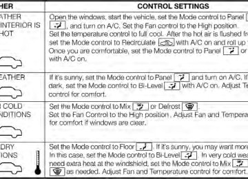
IF YOUR ENGINE OVERHEATS In any of the following situations, you can reduce the potential for overheating by taking the appropriate ac- tion. • On the highways — slow down. • In city traffic — while stopped, place the transmission in NEUTRAL, but do not increase engine idle speed. NOTE: There are steps that you can take to slow down an impending overheat condition: • If your air conditioner (A/C) is on, turn it off. The A/C system adds heat to the engine cooling system and turning the A/C off can help remove this heat.
• You can also turn the temperature control to maximum heat, the mode control to floor and the blower control to high. This allows the heater core to act as a supplement to the radiator and aids in removing heat from the engine cooling system.
272 WHAT TO DO IN EMERGENCIES
CAUTION!
Driving with a hot cooling system could damage your vehicle. If the pointer rises to the H (red) mark, the instrument cluster will sound a chime. When safe, pull over and stop the vehicle with the engine at idle. Turn off the air conditioning and wait until the pointer drops back into the normal range. If the pointer remains on the H (red) mark for more than a minute, turn the engine off immediately and call for service.
WARNING!
You or others can be badly burned by hot engine coolant (antifreeze) or steam from your radiator. If you see or hear steam coming from under the hood, do not open the hood until the radiator has had time to cool. Never try to open a cooling system pressure cap when the radiator or coolant bottle is hot.
TIREFIT KIT Small punctures up to 1/4 in (6 mm) in the tire tread can be sealed with TIREFIT. Foreign objects (e.g., screws or nails) should not be removed from the tire. TIREFIT can be used in outside temperatures down to approximately -4°F (-20°C). This kit will provide a temporary tire seal, allowing you to drive your vehicle up to 100 miles (160 km) with a maximum speed of 55 mph (88 km/h).
TIREFIT Storage The TIREFIT kit is located under the front driver’s seat. TIREFIT Kit Components And Operation
WHAT TO DO IN EMERGENCIES 273
4. Power Button 5. Mode Select Knob 6. Sealant Hose (Clear) 7. Air Pump Hose (Black) 8. Power Plug Using The Mode Select Knob And Hoses Your TIREFIT kit is equipped with the following symbols to indicate the air or sealant mode. Selecting Air Mode
Turn the Mode Select Knob (5) to this position for air pump operation only. Use the Black Air Pump Hose (7) when selecting this mode.
1. Sealant Bottle 2. Deflation Button 3. Pressure Gauge
274 WHAT TO DO IN EMERGENCIES Selecting Sealant Mode
Turn the Mode Select Knob (5) to this position to inject the TIREFIT Sealant and to inflate the tire. Use the Sealant Hose (clear hose) (6) when selecting this mode.
Using The Power Button
Push and release the Power Button (4) once to turn On the TIREFIT kit. Push and release the Power Button (4) again to turn Off the TIREFIT kit.
Using The Deflation Button
Press the Deflation Button (2) to reduce the air pressure in the tire if it becomes over-inflated.
TIREFIT Usage Precautions • Replace the TIREFIT Sealant Bottle (1) and Sealant Hose (6) prior to the expiration date (printed on the bottle label) to assure optimum operation of the sys- tem. Refer to “Sealing a Tire with TIREFIT” section (F) “Sealant Bottle and Hose Replacement”.
• The Sealant Bottle (1) and Sealant Hose (6) are a one tire application use. After each use, always replace these components immediately at an authorized dealer.
• When the TIREFIT sealant is in a liquid form, clean water, and a damp cloth will remove the material from the vehicle or tire and wheel components. Once the sealant dries, it can easily be peeled off and properly discarded.
• For optimum performance, make sure the valve stem on the wheel is free of debris before connecting the TIREFIT kit.
• You can use the TIREFIT air pump to inflate bicycle tires. The kit also comes with two needles, located in the Accessory Storage Compartment (on the bottom of the air pump) for inflating sport balls, rafts, or similar inflatable items. However, use only the Air Pump Hose (7) and make sure the Mode Select Knob (5) is in the Air Mode when inflating such items to avoid injecting sealant into them. The TIREFIT Sealant is only intended to seal punctures less than 1⁄4 in (6 mm) diameter in the tread of your vehicle.
• Do not lift or carry the TIREFIT kit by the hoses.
WHAT TO DO IN EMERGENCIES 275
WARNING!
• Do not attempt to seal a tire on the side of the vehicle closest to traffic. Pull far enough off the road to avoid the danger of being hit when using the TIREFIT kit.
• Do not use TIREFIT or drive the vehicle under the following circumstances: − If the puncture in the tire tread is approximately 1/4 in. (6 mm) or larger. − If the tire has any sidewall damage. − If the tire has any damage from driving with extremely low tire pressure. − If the tire has any damage from driving on a flat tire. − If the wheel has any damage.
(Continued)
276 WHAT TO DO IN EMERGENCIES
WARNING! (Continued)
WARNING! (Continued)
source.
− If you are unsure of the condition of the tire or the wheel. • Keep TIREFIT away from open flames or heat • A loose TIREFIT kit thrown forward in a collision or hard stop could endanger the occupants of the vehicle. Always stow the TIREFIT kit in the place provided. Failure to follow these warnings can result in injuries that are serious or fatal to you, your passengers, and others around you.
(Continued)
• Take care not to allow the contents of TIREFIT to come in contact with hair, eyes, or clothing. TIRE- FIT is harmful if inhaled, swallowed, or absorbed through the skin. It causes skin, eye, and respira- tory irritation. Flush immediately with plenty of water if there is any contact with eyes or skin. Change clothing as soon as possible, if there is any contact with clothing.
• TIREFIT Sealant solution contains latex. In case of an allergic reaction or rash, consult a physician immediately. Keep TIREFIT out of reach of chil- dren. If swallowed, rinse mouth immediately with plenty of water and drink plenty of water. Do not induce physician immediately.
vomiting!
Consult
Sealing A Tire With TIREFIT (A) Whenever You Stop To Use TIREFIT: 1. Pull over to a safe location and turn on the vehicle’s Hazard Warning flashers. 2. Verify that the valve stem (on the wheel with the deflated tire) is in a position that is near to the ground. This will allow the TIREFIT Hoses (6) and (7) to reach the valve stem and keep the TIREFIT kit flat on the ground. This will provide the best positioning of the kit when injecting the sealant into the deflated tire and running the air pump. Move the vehicle as necessary to place the valve stem in this position before proceeding. 3. Place the transmission in PARK (auto transmission) or in Gear (manual transmission) and turn Off the ignition. 4. Set the parking brake.
WHAT TO DO IN EMERGENCIES 277
(B) Setting Up To Use TIREFIT: 1. Turn the Mode Select Knob (5) to the Sealant Mode position. 2. Uncoil the Sealant Hose (6) and then remove the cap from the fitting at the end of the hose. 3. Place the TIREFIT kit flat on the ground next to the deflated tire. 4. Remove the cap from the valve stem and then screw the fitting at the end of the Sealant Hose (6) onto the valve stem. 5. Uncoil the Power Plug (8) and insert the plug into the vehicle’s 12 Volt power outlet. NOTE: Do not remove foreign objects (e.g., screws or nails) from the tire.
278 WHAT TO DO IN EMERGENCIES (C) Injecting TIREFIT Sealant Into The Deflated Tire: • Always start the engine before turning ON the TIRE-
FIT kit.
NOTE: Manual transmission vehicles must have the parking brake engaged and the shift lever in NEUTRAL. • After pressing the Power Button (4), the sealant (white fluid) will flow from the Sealant Bottle (1) through the Sealant Hose (6) and into the tire.
NOTE: Sealant may leak out through the puncture in the tire. If the sealant (white fluid) does not flow within 0 – 10 seconds through the Sealant Hose (6): 1. Press the Power Button (4) to turn Off the TIREFIT kit. Disconnect the Sealant Hose (6) from the valve stem. Make sure the valve stem is free of debris. Reconnect the
Sealant Hose (6) to the valve stem. Check that the Mode Select Knob (5) is in the Sealant Mode position and not Air Mode. Press the Power Button (4) to turn On the TIREFIT kit. 2. Connect the Power Plug (8) to a different 12 Volt power outlet in your vehicle or another vehicle, if avail- able. Make sure the engine is running before turning ON the TIREFIT kit. 3. The Sealant Bottle (1) may be empty due to previous use. Call for assistance. If the Mode Select Knob (5) is on Air Mode and NOTE: the pump is operating, air will dispense from the Air Pump Hose (7) only, not the Sealant Hose (6). If the sealant (white fluid) does flow through the Sealant Hose (6):
1. Continue to operate the pump until sealant is no longer flowing through hose (typically takes 30 - 70 sec- onds). As the sealant flows through the Sealant Hose (6), the Pressure Gauge (3) can read as high as 70 psi (5 Bar). The Pressure Gauge (3) will decrease quickly from ap- proximately 70 psi (5 Bar) to the actual tire pressure when the Sealant Bottle (1) is empty. 2. The pump will start to inject air into the tire immedi- ately after the Sealant Bottle (1) is empty. Continue to operate the pump and inflate the tire to the pressure indicated on the tire pressure label on the driver-side latch pillar (recommended pressure). Check the tire pres- sure by looking at the Pressure Gauge (3). If the tire does not inflate to at least 26 psi (1.8 Bar) pressure within 15 minutes: • The tire is too badly damaged. Do not attempt to drive
the vehicle further. Call for assistance.
WHAT TO DO IN EMERGENCIES 279
If the tire becomes over-inflated, press the NOTE: Deflation Button to reduce the tire pressure to the recom- mended inflation pressure before continuing. If the tire inflates to the recommended pressure or is at least 26 psi (1.8 Bar) pressure within 15 minutes: 1. Press the Power Button (4) to turn off the TIREFIT kit. 2. Remove the Speed Limit sticker from the top of the Sealant Bottle (1) and place the sticker on the instrument panel. 3. Immediately disconnect the Sealant Hose (6) from the valve stem, reinstall the cap on the fitting at the end of the hose, and place the TIREFIT kit in the vehicle storage location. Quickly proceed to (D) “Drive Vehicle”.280 WHAT TO DO IN EMERGENCIES
CAUTION!
• The metal end fitting from Power Plug (8) may get hot after use, so it should be handled carefully. • Failure to reinstall the cap on the fitting at the end of the Sealant Hose (6) can result in sealant con- tacting your skin, clothing, and the vehicle’s inte- rior. It can also result in sealant contacting internal TIREFIT kit components which may cause perma- nent damage to the kit.
(D) Drive Vehicle: Immediately after injecting sealant and inflating the tire, drive the vehicle 5 miles (8 km) or 10 minutes to ensure distribution of the TIREFIT Sealant within the tire. Do not exceed 55 mph (88 km/h).
WARNING!
TIREFIT is not a permanent flat tire repair. Have the tire inspected and repaired or replaced after using TIREFIT. Do not exceed 55 mph (88 km/h) until the tire is repaired or replaced. Failure to follow this warning can result in injuries that are serious or fatal to you, your passengers, and others around you.
(E) After Driving: Pull over to a safe location. Refer to “Whenever You Stop to Use TIREFIT” before continuing. 1. Turn the Mode Select Knob (5) to the Air Mode position. 2. Uncoil the power plug and insert the plug into the vehicle’s 12 Volt power outlet.
3. Uncoil the Air Pump Hose (7) (black in color) and screw the fitting at the end of hose (7) onto the valve stem. 4. Check the pressure in the tire by reading the Pressure Gauge (3). If tire pressure is less than 19 psi (1.3 Bar) , the tire is too badly damaged. Do not attempt to drive the vehicle further. Call for assistance. If the tire pressure is 19 psi (1.3 bar) or higher: 1. Press the Power Button (4) to turn on TIREFIT and inflate the tire to the pressure indicated on the tire and loading information label on the driver-side door open- ing. If the tire becomes over-inflated, press the NOTE: Deflation Button to reduce the tire pressure to the recom- mended inflation pressure before continuing.
WHAT TO DO IN EMERGENCIES 281
2. Disconnect the TIREFIT kit from the valve stem, reinstall the cap on the valve stem and unplug from 12
Volt outlet. 3. Place the TIREFIT kit in its proper storage area in the vehicle. 4. Have the tire inspected and repaired or replaced at the earliest opportunity at an authorized dealer or tire ser- vice center. 5. Replace the Sealant Bottle (1) and Sealant Hose (6) assembly at your authorized dealer as soon as possible. Refer to “(F) Sealant Bottle and Hose Replacement.” NOTE: When having the tire serviced, advise the au- thorized dealer or service center that the tire has been sealed using the TIREFIT service kit. (F) Sealant Bottle And Hose Replacement: 1. Uncoil the Sealant Hose (6) (clear in color).282 WHAT TO DO IN EMERGENCIES 2. Locate the round Sealant Bottle release button in the recessed area under the sealant bottle. 3. Press the Sealant Bottle release button. The Sealant Bottle (1) will pop up. Remove the bottle and dispose of it accordingly. 4. Clean any remaining sealant from the TIREFIT housing. 5. Position the new Sealant Bottle (1) in the housing so that the Sealant Hose (6) aligns with the hose slot in the front of the housing. Press the bottle into the housing. An audible click will be heard indicating the bottle is locked into place. 6. Verify that the cap is installed on the fitting at the end of the Sealant Hose (6) and return the hose to its storage area (located on the bottom of the air pump). 7. Return the TIREFIT kit to its storage location in the vehicle.
JACKING AND TIRE CHANGING — IF EQUIPPED
WARNING!
• Do not attempt to change a tire on the side of the vehicle close to moving traffic. Pull far enough off the road to avoid the danger of being hit when operating the jack or changing the wheel.
• Being under a jacked-up vehicle is dangerous. The vehicle could slip off the jack and fall on you. You could be crushed. Never put any part of your body under a vehicle that is on a jack.
• Never start or run the engine while the vehicle is on a jack. If you need to get under a raised vehicle, take it to a service center where it can be raised on a lift.
(Continued)
WARNING! (Continued)
• The jack is designed to be used as a tool for changing tires only. The jack should not be used to lift the vehicle for service purposes. The vehicle should be jacked on a firm level surface only. Avoid ice or slippery areas.
Jack Location The jack and jack-handle are stowed in a bag under the front driver’s seat.
WHAT TO DO IN EMERGENCIES 283
Jack Stowage
284 WHAT TO DO IN EMERGENCIES Spare Tire Removal The spare tire is stowed to the underbody below the cargo area. 1. Remove the plug located in the rear cargo area.
2. Fit the wrench tool over the drive nut. Use the wrench to rotate the nut counterclockwise until the spare is on the ground with enough slack in the cable to allow you to pull the tire out from under the vehicle.
Winch Access Plug
Lowering/Raising Spare Tire
CAUTION!
The winch mechanism is designed for use with the jack wrench tool only. Use of an air wrench or other power tools is not recommended and they can dam- age the winch.
3. Pull the spare tire out from under the vehicle.
WHAT TO DO IN EMERGENCIES 285
Spare Tire
286 WHAT TO DO IN EMERGENCIES 4. When the spare is clear, remove the knob or plastic molded nut by rotating it counter-clockwise.
5. Tilt the retainer at the end of the cable and pull it through the center of the wheel.
Plastic Molded Nut
Retainer
Preparations For Jacking 1. Park the vehicle on a firm level surface, avoiding ice or slippery areas.
WARNING!
Do not attempt to change a tire on the side of the vehicle close to moving traffic, pull far enough off the road to avoid the danger of being hit when operating the jack or changing the wheel.
2. Turn on the Hazard Warning flashers. 3. Set the parking brake. 4. Place the shift lever in PARK (automatic transmission) or REVERSE (manual transmission). 5. Turn Off the ignition.
WHAT TO DO IN EMERGENCIES 287
6. Block both the front and rear of the wheel diagonally opposite the jacking position. For example, if changing the right tire, block the left rear wheel.front
NOTE: Passengers should not remain in the vehicle while the vehicle is being jacked. Jacking Instructions
WARNING!
Carefully follow these tire changing warnings to help prevent personal injury or damage to your vehicle: • Always park on a firm, level surface as far from the edge of the roadway as possible before raising the vehicle.
(Continued)
288 WHAT TO DO IN EMERGENCIES
WARNING! (Continued) • Turn on the Hazard Warning flashers. • Block the wheel diagonally opposite the wheel to • Set the parking brake firmly and set an automatic transmission in PARK; a manual transmission in REVERSE.
be raised.
WARNING! (Continued)
• To assure that spare tires, flat or inflated, are securely stowed, spares must be stowed with the valve stem facing the ground.
jack.
jack.
• Never start or run the engine with the vehicle on a • Do not let anyone sit in the vehicle when it is on a • Do not get under the vehicle when it is on a jack. • Only use the jack in the positions indicated and • If working on or near a roadway, be extremely (Continued)
for lifting this vehicle during a tire change.
careful of motor traffic.
Jack Warning Label
NOTE: Refer to the “Compact Spare Tire” section of the “Tires-General Information” under “Starting And Oper- ating” for information about the spare tire, it s use, and operation.
CAUTION!
Do not attempt to raise the vehicle by jacking on locations other than those indicated in the Jacking Instructions for this vehicle.
1. Remove the scissors jack and tool bag from under the driver’s seat. 2. Loosen, but do not remove, the wheel bolts by turning them to the left one turn while the wheel is still on the ground. NOTE: There are front and rear jacking locations on each side of the body (as indicated by the triangular lift point symbol on the sill molding).
WHAT TO DO IN EMERGENCIES 289
Front Jacking Location
290 WHAT TO DO IN EMERGENCIES
positioned, turn the jack screw to the right until the jack head is properly engaged with the lift area closest to the wheel to be changed.
Rear Jacking Location
Do not raise the vehicle until you are sure the jack is securely engaged. 3. Turn the jack screw to the left until the jack can be placed under the jacking location. Once the jack is
Jacking Location
WARNING!
WHAT TO DO IN EMERGENCIES 291
WARNING!
Raising the vehicle higher than necessary can make the vehicle less stable. It could slip off the jack and hurt someone near it. Raise the vehicle only enough to remove the tire.
To avoid the risk of forcing the vehicle off the jack, do not fully tighten the wheel bolts until the vehicle has been lowered. Failure to follow this warning may result in personal injury.
4. Using the swivel wrench, raise the vehicle by turning the jack screw to the right. Raise the vehicle only until the tire just clears the surface and enough clearance is obtained to install the spare tire. Minimum tire lift provides maximum stability. 5. Remove the wheel bolts and pull the wheel off the hub. For vehicles equipped with aluminum wheels, the center caps must be removed to remove the wheel bolts.
CAUTION!
Be sure to mount the spare tire with the valve stem facing outward. The vehicle could be damaged if the spare tire is mounted incorrectly.
WARNING!
To avoid possible personal injury, handle the wheel covers with care to avoid contact with any sharp edges.
292 WHAT TO DO IN EMERGENCIES NOTE: The wheel cover is held on the wheel by the wheel bolts. When reinstalling the original wheel, prop- erly align the wheel cover to the valve stem, place the wheel cover onto the wheel, then install the wheel bolts. 6. Install the spare wheel and wheel bolts with the cone shaped end of the bolts toward the wheel. Lightly tighten the bolts. To avoid the risk of forcing the vehicle off the jack, do not tighten the bolts fully until the vehicle has been lowered. 7. Lower the vehicle by turning the jack screw to the left. 8. Finish tightening the bolts. Push down on the wrench while tightening the wheel bolts. Alternate bolts until each bolt has been tightened twice. The correct wheel bolt torque is 63 ft lbs (85 N·m) for steel wheels and 75 ft lbs (100 N·m) for aluminum wheels. If you doubt that you have tightened the bolts correctly, have them checked with a torque wrench by your authorized dealer or service station.
9. Disassemble the jack and tools and place them in the bag. Stow it under the driver’s seat and secure the bag to the floor with the straps attached to the floor of the vehicle.
WARNING!
A loose tire or jack thrown forward in a collision or hard stop could endanger the occupants of the ve- hicle. Always stow the jack parts and the spare tire in the places provided.
10. Place the deflated (flat) tire in the cargo area. Have the tire repaired or replaced as soon as possible.
WARNING!
WHAT TO DO IN EMERGENCIES 293
CAUTION!
A loose tire thrown forward in a collision or hard stop could injure the occupants in the vehicle. Have the deflated (flat) tire repaired or replaced immedi- ately.
11. Check the spare tire pressure as soon as possible. Correct the tire pressure as required. Spare Tire Stowage Reverse instructions of the spare removal section. Rotate the jack wrench tool on the winch drive nut clockwise until effort becomes heavy and an audible click is heard indicating the spare is properly stowed.
The winch mechanism is designed for use with the jack wrench extension tool only. Use of air wrench or power tool may damage the winch.
JUMP-STARTING PROCEDURE If your vehicle has a discharged battery, it can be jump- started using a set of jumper cables and a battery in another vehicle or by using a portable battery booster pack. Jump-starting can be dangerous if done improperly so please follow the procedures in this section carefully. NOTE: When using a portable battery booster pack, follow the manufacturer’s operating instructions and precautions.
294 WHAT TO DO IN EMERGENCIES
WARNING!
Do not attempt jump-starting if the battery is frozen. It could rupture or explode and cause personal injury.
CAUTION!
Do not use a portable battery booster pack or any other booster source with a system voltage greater than 12 Volts or damage to the battery, starter motor, alternator or electrical system may occur. Preparations For Jump-Start The battery in your vehicle is located on the left side of the engine compartment.
Positive Battery Post
1 — Positive Battery Post 2 — Negative Battery Post
WARNING!
• Take care to avoid the radiator cooling fan when- ever the hood is raised. It can start anytime the ignition switch is ON. You can be injured by moving fan blades.
• Remove any metal jewelry such as watch bands or bracelets that might make an inadvertent electrical contact. You could be seriously injured.
• Batteries contain sulfuric acid that can burn your skin or eyes and generate hydrogen gas which is flammable and explosive. Keep open flames or sparks away from the battery.
1. Set the parking brake, shift the automatic transmission into PARK and turn the ignition to OFF/LOCK. 2. Turn off the heater, radio, and all unnecessary electri- cal accessories.
WHAT TO DO IN EMERGENCIES 295
3. If using another vehicle to jump-start the battery, park the vehicle within the jumper cables reach, set the parking brake and make sure the ignition is OFF.WARNING!
Do not allow vehicles to touch each other as this could establish a ground connection and personal injury could result.