- Download PDF Manual
-
buttons to select ⬙EQ User.⬙
3. Use 4. Press MENU button to start adjusting equalizer. 5. On the display a 7 bar graph will appears, in which each bar represents a frequency. Select the bar to be buttons. The selected adjusted by using the or bar will start to flash and it can be adjusted using
or
buttons.
6. To store the setting, press the MENU or AUDIO buttons. Menu MENU Button Functions Press the MENU button briefly to activate the Menu function. buttons to scroll through the menu Use the functions. To change the setting of the selected function, use the
buttons.
or
or
174 UNDERSTANDING YOUR INSTRUMENT PANEL The current status of the selected function appears on the display. The functions managed by the Menu are: • Speech Volume • Aux Audio Offset • Radio Off • Sat ID • SIRIUS威 Telephone Number • System Reset • Speed Volume • On Volume Limit Press the MENU button again to exit the Menu function.
the passenger
Speed Volume Function — If Equipped This function automatically adapts the volume level to the speed of the car, turning up the volume when the speed increases to maintain the ratio with the noise level inside compartment. To activate/ deactivate the function, use the buttons. The wording “Speed volume” appears on the display, followed by the current status of the function: • Off: function deactivated • Low: function activated (low sensitivity) • High: function activated (high sensitivity) On Volume Limit This function makes it possible to activate/deactivate the maximum volume limit when turning the radio on.
The display shows the function status: • “On volume limit: on” – when the radio is turned on
the volume level will be: − If the volume level is equal to or higher than the maximum value, the radio will come on at the maxi- mum volume. − If the volume level is between the minimum and maximum values, the radio will come on at the same volume as before it was switched off. − If the volume level is equal to or lower than the minimum value, the radio will come on at the mini- mum volume.
• “On volume limit: off” – The radio will come on at the same volume as before it was switched off. The volume level can be between 0 and 40.
Use the buttons
or
to change the setting.
UNDERSTANDING YOUR INSTRUMENT PANEL 175
NOTE: • Using the Menu it is only possible to adjust the activation/deactivation of the function and not the minimum or maximum volume value.
• If the battery charge is too low, the volume cannot be adjusted between the minimum and the maximum level.
Radio Off Function This function makes it possible to set the radio switching off mode by choosing between two methods. The chosen mode appears on the display: • “Radio off: 00 min” — The radio turns off in connec- tion with the ignition key; the radio is turned auto- matically off as soon as the key is turned to the STOP position.
176 UNDERSTANDING YOUR INSTRUMENT PANEL • “Radio off: 20 min” — The radio turns off indepen- dently from the ignition key; the radio remains on for a maximum period of 20 minutes after the key has been turned to the STOP position.
System Reset Function This function is used to restore all settings to the factory values. The options are: • NO — No restore intervention. • YES — The default parameters will be restored. Dur- ing such operation, the wording “Resetting” appears on the display. At the end of the operation, the source does not change and the previous situation will be displayed.
Radio (Tuner) Introduction When the car radio is turned on, the last function that was selected before turning it off (Radio, CD, CD MP3, AUX) is activated. To select the Radio function when another audio source is being listened to, briefly press the TUNER button. Once the Radio mode has been activated, the display will show the name (RBDS stations only) or the frequency of the selected radio station, the frequency band selected (e.g. FMA) and the preset button number (e.g. P1). Frequency Band Selection With the Radio mode active, press the FM or AM tuner button briefly and repeatedly to select the desired recep- tion band.
Each time the button is pressed the following bands are selected cyclically: • AM, FM or SAT (if equipped) Each band is highlighted by the corresponding wordings on the display. The radio will be tuned to last station selected on the respective frequency band. Preset Buttons The buttons numbered from 1 to 5 are used to set the following pre-selections: • 15 in the FM band (5 in FMA, 5 in FMB, 5 in FMC • 10 in the AM band (5 in AMA, 5 in AMB) • 15 in SAT (if so equipped) (5 SATA, 5 SATB, 5 SATC) To listen to a preset station, select the desired frequency band and then briefly press the corresponding preset button (from 1 to 5).
or
UNDERSTANDING YOUR INSTRUMENT PANEL 177
By pressing the preset button for more than 2 seconds, the tuned station will be stored. Pressing the A-B-C button will change between the preset memory group in the current frequency band. Automatic Tuning Briefly press the button to start the automatic tuning search for the next station that can be received in the selected direction. button is pressed for longer, the rapid If the search is started. When the button is released, the tuner will stop on the next station that can be received. Manual Tuning This is used to manually search for stations in the preselected band. Select the desired frequency band and then press briefly button to start the search and repeatedly theor
or
or
is weak, the reproduction is
178 UNDERSTANDING YOUR INSTRUMENT PANEL in the desired direction. If the button is pressed longer, the fast search starts and then stops when the button is released. Stereophonic Broadcasters If the incoming signal automatically switched from Stereo to Mono. SIRIUS姞 Satellite Radio — If Equipped Satellite Radio Antenna — If Equipped The antenna for the satellite radio is mounted on the roof of the vehicle. Do not place items on the roof around the roof top antenna location. Objects placed within the line of sight of the antenna will cause decreased performance. Larger luggage items should be placed as far from the antenna as possible. Do not place items directly on or above the antenna.
SIRIUS威 Satellite Radio With over 130 channels, SIRIUS威 Satellite Radio brings you more of what you love. Get 69 channels of 100% commercial-free music, plus all of your favorite sports, news, talk and entertainment. Hear every NFL game, every NASCAR race, college sports and more. The big- gest and most compelling names in talk with Howard Stern and Martha Stewart, laugh-out-loud comedy with Jamie Foxx’s The Foxxhole and Blue Collar Comedy, plus kids’ programming, world-class news, local traffic and weather. All of this with crystal clear, coast-to-coast coverage. Everything worth listening to is now on SIRIUS. A one-year SIRIUS威 Satellite Radio subscription is included. SIRIUS XM and all related marks and logos are trademarks of SIRIUS XM Radio Inc. and its subsid- iaries. SIRIUS Radio requires a subscription, sold sepa- rately after trial subscription included with vehicle pur- chase. Prices and programming are provided by SIRIUS and are subject to change. Subscriptions governed by
in Canada;
Terms & Conditions available at sirius.com/service terms. SIRIUS Radio U.S. service only available to those at least 18 years of age in the 48 contiguous United States, D.C., and PR. Service available see www.siriuscanada.ca. SIRIUS威 Satellite Radio Program Types Program Types can be selected by pressing the
or buttons. The Program Type will change to the next category and the radio will then tune to first station in buttons will tune that program type. Pressing to only the stations in that program type. Pressing the will allow normal tuning to all stations. The Program Types available are: All, Pop, Rock, Electronic/Dance, Hip-Hop/R&B, Country, Christian, Jazz/Standards, Classical, Latin/World, Sports, Enter- tainment, Talk, News, NPR, Comedy, Family & Health, Religion, Traffic/Weather.
buttons until ⬙All⬙ is displayed
or
or
UNDERSTANDING YOUR INSTRUMENT PANEL 179
You can find SIRIUS’ current terms and conditions at http://www.sirius.com. Re-Subscribe To SIRIUS威 Satellite Radio New vehicle purchasers or lessees will receive a free limited time subscription to SIRIUS威 Satellite Radio with their radio. Following expiration of the free services, it will be necessary to access the information on the Sub- scription Information screen in order to re-subscribe. Press the UP/DOWN button to scroll through the Menu Functions, and the Left/Right button to change the selected Set-up Menu function. Write down the Electronic Serial Number (ESN) for your receiver. To retrieve the Electronic Serial Number of SIRIUS Satellite Receiver Module tune to Channel 0. Make sure that when the order is placed, the ESN are correct. If any of the ESN numbers are not entered correctly, then the SIRIUS subscription will not be able to be transferred to the new radio and will not be active180 UNDERSTANDING YOUR INSTRUMENT PANEL when installed in the customer’s vehicle. To reactivate your service, either call the number listed on the display or visit the provider online.
CAUTION!
Neither SIRIUS nor FIAT is responsible for any errors in accuracies in the SIRIUS data services or its use in vehicles.
SIRIUS XM and all related marks and logos are trade- marks of SIRIUS XM Radio Inc. and its subsidiaries. SIRIUS Radio requires a subscription, sold separately after trial subscription included with vehicle purchase. Prices and programming are provided by SIRIUS and are subject to change. Subscriptions governed by Terms & Conditions available at sirius.com/service terms. SIRIUS Radio U.S. service only available to those at least 18 years of age in the 48 contiguous United States, D.C., & PR. Visit www.sirius.com
Sirius Subscription Issues When Replacing A Sirius Radio When a radio needs to be replaced, the dealer will need the SIRIUS information to order a new radio (even if the SIRIUS subscription has lapsed). The ESN number con- tains 12 digits. The following are instructions for retrieving the Elec- tronic Serial Number (ESN) from FIAT 500 NAFTA model radios: To retrieve the ESN of SIRIUS Satellite Receiver Module tune to Channel 0. Make sure that when the order is placed, the ESN are correct. If any of the ESN numbers are not entered correctly, then the SIRIUS subscription will not be able to be transferred to the new radio and will not be active when installed in the customer’s vehicle.
CD Player Introduction This chapter describes the operation of the CD player only. To operate the radio, refer to the description in the “Functions and Adjustments” chapter. CD Player Selection To activate the CD player built into the equipment, proceed as follows: • Load a CD with the equipment switched on. The first
track will start to play.
or • If a CD has already been loaded, turn on the radio and then briefly press the MEDIA button to select the “CD” function mode. The last track listened to will start to play.
UNDERSTANDING YOUR INSTRUMENT PANEL 181
It is advisable to use original CDs to ensure optimal playing. If CD-R/RWs are used, we recommend using good quality media that are burned at the slowest speed possible. CD Loading/Ejecting To load the CD, insert it gently into the slot to activate the motorized loading system, which will position it cor- rectly. The CD can be loaded with the radio off and the ignition key turned to ON/RUN. In this case, the radio will remain off. When the radio is turned on, the last source listened to before being switched off, will be activated. When a CD is inserted, the display will show the symbol “CD” and the wording “CD Reading.” They will remain displayed for the whole time required for the radio to read the CD. When this time has elapsed the radio automatically starts playing the first track.182 UNDERSTANDING YOUR INSTRUMENT PANEL Press the button with the radio turned on, to activate the motorized CD ejection system. After ejection, the last audio source listened to before playing the CD will be heard. If the CD is not removed from the radio, it will automati- cally be reloaded about 20 seconds later but will not resume playing until the ⬙MEDIA⬙ button is pressed to select the CD mode. The radio will switch to the last source prior to CD mode. The CD cannot be ejected if the radio is off. Possible Error Messages If the loaded CD cannot be read (e.g. a CD ROM has been inserted or the CD is inserted the wrong way or there is a reading error) the display shows the wording “CD Disc error.” The CD will then be ejected and the audio source activated before the CD mode selection will be heard.
A CD which cannot be read will not be ejected until these functions are over. At the end, with the CD mode activated, the display will show the wording “CD Disc error” for a few seconds and then the CD will be ejected. Display Information When the CD player is operating, information will ap- pear on the display with the following meaning: • “Track 5” indicates the CD track number. • “03:42” indicates the time elapsed since the start of the
track (if the relevant Menu function is activated).
Track Selection button to play the previous CD track Briefly press the button to play the next track. The tracks are and the selected cyclically: the first track is selected after the last track and vice versa. If the track has been played for more than 3 seconds, button, starts the track again from the pressing the
button twice consecutively.
beginning. In this case, if you want to play the previous track, press the Track Fast Forward/Rewind button pressed down to fast forward the Keep the button pressed down to selected track and keep the fast rewind the track. The fast forward/rewind will stop once the button is released. Pause Function To pause the CD player, press the wording “CD Pause” appears on the display. To resume listening to the track, press the again. CD MP3 Player Introduction This chapter describes the operation of the CD MP3
player.button. The
button
UNDERSTANDING YOUR INSTRUMENT PANEL 183
NOTE: Layer-3 audio decoding technology is licensed from Fraunhofer IIS and Thomson multimedia. MP3 Mode In addition to playing regular audio CDs, the radio is also enabled to play CDROMs on which compressed audio files have been recorded in an MP3 format. To guarantee optimal reproduction, it is advisable to use good quality CDs burned at the lowest speed possible. The files on an MP3 CD are structured in folders that create lists of all the folders containing MP3 tracks (folders or subfolders are all on the same level). The folders that do not contain MP3 tracks cannot be selected. The specifications and operating conditions for playing MP3 files are the following: • The CD-ROMs used should be burned in accordancewith ISO standard 9660.
184 UNDERSTANDING YOUR INSTRUMENT PANEL • The music files should have the extension “.mp3” or “.wma” files with a different extension will not be reproduced.
• The sampling frequencies that can be reproduced are: 44.1 kHz, stereo (from 96 to 320 kbit/s) – 22.05 kHz, mono or stereo (from 32 to 80 kbit/s).
• Tracks with a variable bit-rate can be reproduced. NOTE: The track names must not include the following characters: spaces, ‘ (apostrophes), ( and ) (open and close brackets). During the burning of a MP3 CD, make sure that the names of the files do not contain these characters; if not, the radio will not be able to play the tracks involved. Selecting MP3 Sessions With Hybrid Discs If a hybrid disc is inserted (Mixed Mode, Enhanced, CD-Extra) also containing MP3 files, the radio automati- cally starts playing the audio session. It is possible to
move to the MP3 session while playing by keeping the CD button pressed for more than 2 seconds. NOTE: When the function is activated the radio may take a few seconds to start playing. While checking the disc the display will show “CD Reading.” If no MP3 files are detected, the radio will resume playing the audio session from the point where it was interrupted. Display Information ID3–Tag Information Display In addition to the information relating to the time elapsed, folder name and file name, the radio is also capable of displaying ID3–TAG information relating to Title Track, Artist and Author. When one of the ID3-TAG pieces of information is chosen to be displayed (Title, Artist, Album) and this informa- tion has not been recorded for the track played, the text ⬙UNKNOWN⬙ will be displayed for that field.
button to select a next folder or the
Selection Of Next/Previous Folder Press the button to select the previous folder. The display will show the number of the folder. The folders are selected cyclically. The first folder is selected after the last folder and vice versa. If no other folder/track is selected in the next 2 seconds, the first track on the new folder will be played. At that moment selected the last track in the folder is playing, the next folder will be played. Structure Of The Folders The radio with MP3 player: • Recognizes only the folders that effectively contain
MP3 format files
UNDERSTANDING YOUR INSTRUMENT PANEL 185
• If the MP3 files on a CD-ROM are structured in sub-folders their structure is compressed to a single level structure, where the sub-folders are taken to the level of the main folders.Troubleshooting General Sound Volume Low The Fader function should be adjusted to the values “F” (front) only to prevent the reduction in radio output power and the cancelling of the volume if the Fader level adjustment is equal to R+9. Source Can Not Be Selected Nothing has been loaded. Load the CD or the MP3 CD to be listened to.
186 UNDERSTANDING YOUR INSTRUMENT PANEL CD Player The Cd Does Not Play The CD is dirty. Clean the CD. The CD is scratched. Try using another CD. The Cd Can Not Be Loaded A CD is already loaded. Press the the CD. MP3 File Reading Track Skips While Playing Mp3 Files The CD is scratched or dirty. The Duration Of The Mp3 Tracks Is Not Correctly Displayed. In some cases (due to the recording mode) the duration of the MP3 tracks can be displayed incorrectly.
button and remove
Operating Instructions — Hands-Free Phone (If Equipped) Refer to the appropriate “BLUE&ME™ User’s Manual” for further information. Personal/Portable Navigation Device (PND) — If Equipped A Personal/Portable Navigation Device (PND) is avail- able as optional equipment for this vehicle, refer to the Navigation User Guide for further information. iPod姞/USB/MEDIA PLAYER CONTROL — IF EQUIPPED This feature allows an iPod威 or external USB device to be plugged into the USB port, located in the glove compart- ment.
UNDERSTANDING YOUR INSTRUMENT PANEL 187
STEERING WHEEL AUDIO CONTROLS The remote sound system controls are located on the rear surface of the steering wheel. Reach behind the wheel to access the switches.
1 — iPod威 Or External USB Device Holder 2 — Cable Jack 3 — USB Connector Refer to the appropriate Blue&Me™ radio User’s Manual for iPod威 or external USB device support capability.
Remote Sound System Controls (Back View Of Steering
Wheel)
188 UNDERSTANDING YOUR INSTRUMENT PANEL The right-hand control is a rocker-type switch with a pushbutton in the center and controls the volume and mode of the sound system. Pressing the top of the rocker switch will increase the volume, and pressing the bottom of the rocker switch will decrease the volume. Pressing the center button will make the radio switch between the various modes available (AM/FM/SAT/ CD/AUX/Media Player, etc.) and can also be used to select/enter an item while scrolling through menu. The left-hand control is a rocker-type switch with a pushbutton in the center. The function of the left-hand control is different depending on which mode you are in. The following describes the left-hand control operation in each mode.
Radio Operation Pressing the top of the switch will “Seek” up for the next listenable station and pressing the bottom of the switch will “Seek” down for the next listenable station. The button located in the center of the left-hand control will tune to the next preset station that you have pro- grammed in the radio preset pushbutton. CD Player Operation Pressing the top of the switch once will go to the next track on the CD. Pressing the bottom of the switch once will go to the beginning of the current track, or to the beginning of the previous track if it is within one second after the current track begins to play. If you press the switch up or down twice, it plays the second track; three times, it will play the third, etc.
Operating Instructions — Hands-Free Phone (If Equipped) Refer to the appropriate Blue&Me™ User’s Manual for further information. CD/DVD DISC MAINTENANCE To keep a CD/DVD in good condition, take the following precautions: 1. Handle the disc by its edge; avoid touching the surface. 2. If the disc is stained, clean the surface with a soft cloth, wiping from center to edge. 3. Do not apply paper or tape to the disc; avoid scratch- ing the disc. 4. Do not use solvents such as benzene, thinner, cleaners, or anti-static sprays. 5. Store the disc in its case after playing.
UNDERSTANDING YOUR INSTRUMENT PANEL 189
6. Do not expose the disc to direct sunlight. 7. Do not store the disc where temperatures may become too high. If you experience difficulty in playing a particu- NOTE: lar disc, it may be damaged (i.e., scratched, reflective coating removed, a hair, moisture or dew on the disc) oversized, or have protection encoding. Try a known good disc before considering disc player service. RADIO OPERATION AND MOBILE PHONES Under certain conditions, the mobile phone being on in your vehicle can cause erratic or noisy performance from your radio. This condition may be lessened or eliminated by relocating the mobile phone antenna. This condition is not harmful to the radio. If your radio performance does not satisfactorily “clear” by the repositioning of the antenna, it is recommended that the radio volume be turned down or off during mobile phone operation.
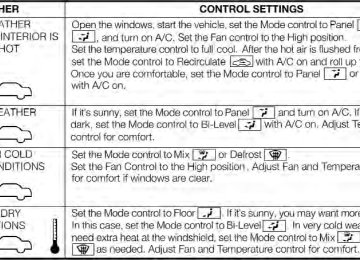
190 UNDERSTANDING YOUR INSTRUMENT PANEL CLIMATE CONTROLS The air conditioning and heating system is designed to make you comfortable in all types of weather. Manual Heating And Air Conditioning
Manual Temperature Control (MTC)
The Manual Climate controls consist of a series of rotary dials and one inner push knob.
1. Temperature Control Rotate this control to regulate the temperature of the air inside the passenger compartment. Rotating the dial to the left into the blue area of the scale indicates cooler temperatures, while rotating to the right into the red area indicates warmer temperatures. 2. Blower Control Rotate this control to regulate the amount of air forced through the ventilation system in any mode. The blower speed increases as you move the control to the right from the “0” (OFF) position. There are four blower speeds. 3. Recirculation Control Rotate this control to change the system between recir- culation mode and outside air mode. Recirculation can be used when outside conditions such as smoke, odors, dust, or high humidity are present.
NOTE: • Continuous use of the Recirculation mode may make the inside air stuffy and window fogging may occur. Extended use of this mode is not recommended.
• The use of the Recirculation mode in cold or damp weather could cause windows to fog on the inside, because of moisture buildup inside the vehicle. Select the outside air position for maximum defogging.
• Recirculation can be used in all modes except for
Defrost and Mix.
• The A/C can be deselected manually without disturb-
ing the mode control selection.
4. Mode Control Rotate this control to change the system between Modes (Panel, Bi-Level, Floor, Mix, Defrost).
UNDERSTANDING YOUR INSTRUMENT PANEL 191
• Panel
Air is directed through the outlets in the instrument panel. These outlets can be adjusted to direct airflow. NOTE: The center instrument panel outlets can be aimed so that they are directed toward the rear seat passengers for maximum airflow to the rear. • Bi-Level
Air is directed through the panel and floor outlets.
• Floor
Air is directed through the floor outlets with a small amount flowing through the defrost and side
window demister outlets. • Mix
Air is directed through the floor, defrost, and side window demister outlets. This setting works best in cold or snowy conditions that require extra heat to
192 UNDERSTANDING YOUR INSTRUMENT PANEL the windshield. This setting is good for maintaining comfort while reducing moisture on the windshield. • Defrost
Air is directed through the windshield and side window demister outlets. Use this mode with maximum blower and temperature settings for best windshield and side window defrosting. NOTE: The air conditioning compressor operates in Mix or Defrost, even if the Air Conditioning (A/C) button is not pressed. This dehumidifies the air to help dry the windshield. To improve fuel economy, use these modes only when necessary.
5. A/C Button Press this button to engage the Air Conditioning. A light will illuminate when the Air Conditioning system is engaged. MAX A/C For maximum cooling, use the A/C and recirculation modes at the same time. ECONOMY MODE If economy mode is desired, press the A/C button to turn OFF the indicator light and the A/C compressor. Then, move the temperature control to the desired temperature.
Operating Tips Chart
UNDERSTANDING YOUR INSTRUMENT PANEL 193
194 UNDERSTANDING YOUR INSTRUMENT PANEL Automatic Temperature Control (ATC) — If Equipped • The Automatic Temperature Control (ATC) allows the
driver to select individual comfort settings.
• The system provides set-and-forget operation for op-
timum comfort and convenience.
• The system can be controlled manually, if desired. The ATC system automatically maintains the interior comfort level desired by the driver and passenger.
Automatic Temperature Control (ATC)
1. AUTO Temperature Control (ATC) Button Controls airflow, temperature, distribution, and air recir- culation automatically. Press and release to select. Per- forming this function will cause the ATC to switch between manual mode and automatic modes. Refer to “Automatic Operation” for more information.
2. A/C Button Press and release to change the current Air Conditioning (A/C) setting. Performing this function will cause the ATC to switch into manual mode. 3. Temperature Control Up Button Provides temperature up control. Push the button for warmer temperature settings. 4. Blower Control Up Button There are 12 blower speeds. The blower speed increases as you press this button. Performing this function will cause the ATC to switch into manual mode. 5. Mix Mode Air is directed through the floor, defrost, and side win- dow demister outlets. This setting works best in cold or snowy conditions that require extra heat to the wind- shield. This setting is good for maintaining comfort while reducing moisture on the windshield. Performing this function will cause the ATC to switch into manual mode.
UNDERSTANDING YOUR INSTRUMENT PANEL 195
6. Front Defrost Press and release to change the current setting. The indicator illuminates when ON. The blower will auto- matically default to medium-high if the Defrost mode is selected. Performing this function will cause the ATC to switch into manual mode. 7. Floor Mode Air is directed through the floor outlets with a small amount flowing through the defrost and side window demister outlets. 8. Panel Mode Air is directed through the outlets in the instrument panel. These outlets can be adjusted to direct airflow. Performing this function will cause the ATC to switch into manual mode. NOTE: The center instrument panel outlets can be aimed so that they are directed toward the rear seat passengers for maximum airflow to the rear.
196 UNDERSTANDING YOUR INSTRUMENT PANEL 9. Blower Control Down Button There are 12 blower speeds. The blower speed decreases as you press this button. Performing this function will cause the ATC to switch into manual mode. 10. Temperature Control Down Button Provides temperature down control. Push the button for cooler temperature settings. 11. Climate Control ON/OFF Button Press and release to turn the Climate Control ON or OFF. 12. Recirculation Control Button Press and release to change the current setting. The indicator illuminates when ON. NOTE: • When in Defrost mode, the Recirculation button will flash if pressed. This indicates that you can not pro- ceed to this mode due to fogging risk.
• When the Auto indicator is on and the Recirculation indicator is off, the Recirculation is in AUTO mode. If the Recirculation indicator is on, the Recirculation setting is manual and Recirculation is on.
Automatic Operation 1. Press the AUTO button on the Automatic Temperature Control (ATC) Panel, the indicator will illuminate when on. 2. Next, adjust the temperature you would like the system to maintain by adjusting the temperature control buttons. Once the desired temperature is displayed, the system will achieve and automatically maintain that comfort level. 3. When the system is set up for your comfort level, it is not necessary to change the settings. You will experience the greatest efficiency by simply allowing the system to function automatically.
NOTE: • It is not necessary to move the temperature settings for cold or hot vehicles. The system automatically adjusts the temperature, mode and fan speed to provide comfort as quickly as possible.
• The temperature can be displayed in U.S. or Metric units by selecting the US/M customer-programmable feature. Refer to the “Electronic Vehicle Information Center (EVIC) — Customer-Programmable Features” in this section of the manual.
To provide you with maximum comfort in the Automatic mode during cold start-ups, the blower fan will remain on low until the engine warms up. The blower will increase in speed and transition into AUTO mode. Manual Operation This system offers a full complement of manual override features.
UNDERSTANDING YOUR INSTRUMENT PANEL 197
NOTE: Each of these features operates independently from each other. If any feature is controlled manually, temperature control will continue to operate automati- cally.Blower Control
There are 12 fixed blower speeds. Use the blower control up or down buttons to regulate the amount of air forced through the system in any mode you select. The blower speed increases as you press or hold the blower control up button and decreases when you press or hold the blower control down button. The blower fan speed can be set to any fixed speed by pressing the blower control up or down buttons. The fan will now operate at a fixed speed until additional speeds are selected. This allows the front occupants to control the volume of air circulated in the vehicle and cancel the AUTO mode.
198 UNDERSTANDING YOUR INSTRUMENT PANEL The operator can also select the direction of the airflow by selecting one of the following positions. Panel Mode
Air comes from the outlets in the instrument panel. Each of these outlets can be individually adjusted to direct the flow of air. The air vanes of the center outlets and outboard outlets can be moved up and down or side to side to regulate airflow direction. There is a shut off wheel located below the air vanes to shut off or adjust the amount of airflow from these outlets. Floor Mode
Air comes from the floor outlets. A slight amount of air is directed through the defrost and side window
demister outlets. Bi-Level
Air is directed through the panel and floor outlets. Press and release the Panel mode button and Floor
mode button to enter Bi-Level mode, the indicators illuminate when ON. Performing this function will cause the ATC to switch into manual mode. Mix Mode
Air comes from the floor, defrost and side window demister outlets. This mode works best in cold or snowy conditions. It allows you to stay comfortable
while keeping the windshield clear. Defrost Mode
Air comes from the windshield and side window demister outlets. Use Defrost mode with maximum temperature settings for best windshield and side win- dow defrosting. When the defrost mode is selected, the blower will automatically default to medium-high. NOTE: While operating in the other modes, the system will not automatically sense the presence of fog, mist or ice on the windshield. Defrost mode must be manually selected to clear the windshield and side glass.
Air Conditioning (A/C) The Air Conditioning (A/C) button allows the operator to manually activate or deactivate the air conditioning system. When in A/C mode with the ATC set to a cool temperature, dehumidified air flows through the air outlets. If Economy mode is desired, press the A/C button to turn off the A/C mode in the ATC display and deactivate the A/C system. NOTE: • If the system is in Mix or Defrost Mode, the A/C can be turned off, but the A/C system shall remain active to prevent fogging of the windows.
• If fog or mist appears on the windshield or side glass,
select Defrost mode and increase blower speed.
UNDERSTANDING YOUR INSTRUMENT PANEL 199
Recirculation Control
When outside air contains smoke, odors, or high humidity, or if rapid cooling is desired, you may wish to recirculate interior air by pressing the RECIRCULATION control button. Recirculation mode should only be used temporarily. The recirculation LED will illuminate when this button is selected. Push the button a second time to turn off the Recirculation mode LED and allow outside air into the vehicle. In cold weather, use of Recirculation mode may NOTE: lead to excessive window fogging. The Recirculation mode is not allowed in the Defrost mode to improve window clearing operation. Recirculation will be dis- abled automatically if this mode is selected.
200 UNDERSTANDING YOUR INSTRUMENT PANEL Operating Tips Window Fogging Windows will fog on the inside when the humidity inside the vehicle is high. This often occurs in mild or cool temperatures when it’s rainy or humid. In most cases, turning the air conditioning (pressing the A/C button) on will clear the fog. Adjust the temperature control, air direction, and blower speed to maintain comfort. As the temperature gets colder, it may be necessary to direct air onto the windshield. Adjust the temperature control and blower speed to maintain comfort. Higher blower speeds will reduce fogging. Interior fogging on the windshield can be quickly removed by selecting the DEFROST mode. Regular cleaning of the inside of the windows with a non-filming cleaning solution (vinegar and water works very well) will help prevent contaminates (cigarette
smoke, perfumes, etc.) from sticking to the windows. Contaminates increase the rate of window fogging. Summer Operation In some cases during high temperature opera- NOTE: tion, the air conditioning system performance may be reduced. This is to help protect the engine from overheat- ing during the high load condition. Your air conditioning system is also equipped with an automatic recirculation system. When the system senses a heavy load or high heat conditions, it may use Recir- culation A/C mode to provide additional comfort while in automatic mode. Winter Operation When operating the system during the winter months, make sure the air intake, located directly in front of the windshield, snow, or other obstructions.
free of
slush,
ice,
is
Vacation Storage Anytime you store your vehicle, or keep it out of service (i.e., vacation) for two weeks or more, run the air conditioning system at idle for about five minutes in the fresh air using the high blower setting. This will ensure adequate system lubrication to minimize the possibility of compressor damage when the system is started again.
UNDERSTANDING YOUR INSTRUMENT PANEL 201
STARTING AND OPERATING
CONTENTS
䡵 Starting Procedures . . . . . . . . . . . . . . . . . . . . 207
▫ Manual Transmission – If Equipped . . . . . . . 207
▫ Automatic Transmission – If Equipped . . . . . 207
▫ Normal Starting . . . . . . . . . . . . . . . . . . . . . 207
▫ Cold Weather Operation . . . . . . . . . . . . . . . 208
▫ If Engine Fails To Start . . . . . . . . . . . . . . . . 208
▫ After Starting . . . . . . . . . . . . . . . . . . . . . . . 209
䡵 Manual Transmission — If Equipped . . . . . . . . 209
▫ Five-Speed Manual Transmission . . . . . . . . . 209▫ Recommended Shift Speeds . . . . . . . . . . . . . 210
▫ Downshifting . . . . . . . . . . . . . . . . . . . . . . . 211
䡵 Automatic Transmission — If Equipped . . . . . . 211
▫ Key Ignition Park Interlock . . . . . . . . . . . . . 212
▫ Brake/Transmission Shift Interlock System . . 212
▫ Six-Speed Automatic Transmission . . . . . . . . 212
▫ Gear Ranges . . . . . . . . . . . . . . . . . . . . . . . . 213
䡵 AutoStick威 — If Equipped . . . . . . . . . . . . . . . 218
▫ Operation . . . . . . . . . . . . . . . . . . . . . . . . . 219204 STARTING AND OPERATING
䡵 Driving Through Water
▫ General Information . . . . . . . . . . . . . . . . . . 219
䡵 Driving On Slippery Surfaces . . . . . . . . . . . . . 220
▫ Acceleration . . . . . . . . . . . . . . . . . . . . . . . . 220
▫ Traction . . . . . . . . . . . . . . . . . . . . . . . . . . . 221
. . . . . . . . . . . . . . . . . 221
▫ Flowing/Rising Water . . . . . . . . . . . . . . . . . 221
. . . . . . . . . . . . . . . 222
▫ Shallow Standing Water 䡵 Power Steering . . . . . . . . . . . . . . . . . . . . . . . 223
䡵 Parking Brake . . . . . . . . . . . . . . . . . . . . . . . . 224
䡵 Sport Mode . . . . . . . . . . . . . . . . . . . . . . . . . . 226
▫ Manual Transmission – If Equipped . . . . . . . 226
▫ Automatic Transmission – If Equipped . . . . . 227
䡵 Brake System . . . . . . . . . . . . . . . . . . . . . . . . 228▫ Four-Wheel Anti-Lock Brake System (ABS)
. . 228
䡵 Electronic Brake Control System . . . . . . . . . . . 229
▫ Anti-Lock Brake System (ABS) . . . . . . . . . . . 230
▫ Brake Assist System (BAS) . . . . . . . . . . . . . . 230
▫ Traction Control System (TCS) . . . . . . . . . . . 231
▫ Hill Start Assist (HSA) . . . . . . . . . . . . . . . . 231
▫ Electronic Stability Control (ESC) . . . . . . . . . 232
▫ ESC Activation/Malfunction Indicator LightAnd ESC Off Indicator Light
. . . . . . . . . . . . 235
䡵 Tire Safety Information . . . . . . . . . . . . . . . . . 236
▫ Tire Markings . . . . . . . . . . . . . . . . . . . . . . . 236
▫ Tire Identification Number (TIN) . . . . . . . . . 240
▫ Tire Terminology And Definitions . . . . . . . . . 241▫ Tire Loading And Tire Pressure . . . . . . . . . . 242
䡵 Tires — General Information . . . . . . . . . . . . . 246
. . . . . . . . . . . . . . . . . . . . . . . 246
▫ Tire Pressure ▫ Tire Inflation Pressures . . . . . . . . . . . . . . . . 247
▫ Tire Pressures For High Speed Operation . . . 248
▫ Radial-Ply Tires . . . . . . . . . . . . . . . . . . . . . 249
▫ Compact Spare Tire . . . . . . . . . . . . . . . . . . . 249
▫ Tire Spinning . . . . . . . . . . . . . . . . . . . . . . . 250
▫ Tread Wear Indicators . . . . . . . . . . . . . . . . . 251
▫ Life Of Tire . . . . . . . . . . . . . . . . . . . . . . . . 252
▫ Replacement Tires . . . . . . . . . . . . . . . . . . . . 252
䡵 Tire Chains . . . . . . . . . . . . . . . . . . . . . . . . . . 253
. . . . . . . . . . . 255
䡵 Tire Rotation RecommendationsSTARTING AND OPERATING 205
䡵 Tire Pressure Monitoring System (TPMS) . . . . . 256
▫ Base System . . . . . . . . . . . . . . . . . . . . . . . . 258
▫ General Information . . . . . . . . . . . . . . . . . . 260
䡵 Fuel Requirements . . . . . . . . . . . . . . . . . . . . . 261
▫ Reformulated Gasoline . . . . . . . . . . . . . . . . 261
▫ Gasoline/Oxygenate Blends . . . . . . . . . . . . . 262
▫ E-85 Usage In Non-Flex Fuel Vehicles . . . . . . 262
▫ MMT In Gasoline . . . . . . . . . . . . . . . . . . . . 263
▫ Materials Added To Fuel . . . . . . . . . . . . . . . 263
▫ Fuel System Cautions . . . . . . . . . . . . . . . . . 264
▫ Carbon Monoxide Warnings . . . . . . . . . . . . 265
. . . . . . . . . . . . . . . . . . . . . . . . . 266
. . . . . . . . . . . . . . 266▫ Fuel Filler Cap (Gas Cap)
䡵 Adding Fuel
206 STARTING AND OPERATING
▫ Loose Fuel Filler Cap Message . . . . . . . . . . . 267
䡵 Trailer Towing . . . . . . . . . . . . . . . . . . . . . . . . 267䡵 Recreational Towing (Behind Motorhome, Etc.)
. . 268
▫ Towing This Vehicle Behind Another Vehicle . . 268STARTING PROCEDURES Before starting your vehicle, adjust your seat, adjust both inside and outside mirrors, and fasten your seat belts.
WARNING!
Never leave children in the vehicle alone. Leaving unattended children in a vehicle is dangerous for a number of reasons. The child or others could be seriously or fatally injured. The child could operate power windows, other controls or move the vehicle. Manual Transmission – If Equipped Apply the parking brake, place the shift lever in NEU- TRAL, and press the clutch pedal before starting the vehicle. This vehicle is equipped with a clutch interlock- ing ignition system. It will not start unless the clutch pedal is pressed to the floor.
STARTING AND OPERATING 207
Automatic Transmission – If Equipped The shift lever must be in the PARK or NEUTRAL position before you can start the engine. Apply the brakes before shifting to any driving gear. NOTE: You must press the brake pedal before shifting out of PARK. Normal Starting NOTE: Normal starting of either a cold or a warm engine is obtained without pumping or pressing the accelerator pedal. Turn the ignition switch to the AVV (START) position and release it when the engine starts. If the engine fails to start within 10 seconds, turn the ignition switch to the STOP (OFF/LOCK) position, wait 10 to 15 seconds, then repeat the Normal Starting procedure.
208 STARTING AND OPERATING Cold Weather Operation To prevent possible engine damage while starting at low temperatures, this vehicle will inhibit engine cranking when the ambient temperature is less than –22° F (–30° C) and the oil temperature sensor reading indicates an engine block heater has not been used. An externally- powered electric engine block heater is available as optional equipment or from your authorized dealer. The message ⬙plug in engine heater⬙ will be displayed in the instrument cluster when the ambient temperature is below 5° F (–15° C) at the time the engine is shut off as a reminder to avoid possible crank delays at the next cold start.
CAUTION!
Use of the recommended SAE 5W-30 oil and adher- ing to the prescribed oil change intervals is important to prevent engine damage and ensure satisfactory starting in cold conditions.
If Engine Fails To Start
WARNING!
Never pour fuel or other flammable liquids into the throttle body air inlet opening in an attempt to start the vehicle. This could result in a flash fire causing serious personal injury.
CAUTION!
• Do not attempt to push or tow your vehicle to get it started. Vehicles equipped with an automatic transmission cannot be started this way. Unburned fuel could enter the catalytic converter and once the engine has started, ignite and damage the converter and vehicle.
(Continued)
CAUTION! (Continued)
• To prevent damage to the starter, do not continu- ously crank the engine for more than 15 seconds at a time. Wait 10 to 15 seconds before trying again.
After Starting The idle speed will automatically decrease as the engine warms up. MANUAL TRANSMISSION — IF EQUIPPED Five-Speed Manual Transmission
WARNING!
You or others could be injured if you leave the vehicle unattended without having the parking brake fully applied. The parking brake should al- ways be applied when the driver is not in the vehicle, especially on an incline.
STARTING AND OPERATING 209
Shift Lever
Fully press the clutch pedal before you shift gears. As you release the clutch pedal, lightly press the accelerator pedal. NOTE: To shift into REVERSE from NEUTRAL, lift the ring under the knob and, at the same time move the gearshift lever to the right and then backward.
210 STARTING AND OPERATING Use each gear in numerical order; do not skip a gear. Be sure the transmission is in first gear, not third, when starting from a standing position. Damage to the clutch can result from starting in third gear. For most city driving, you will find it easier to use only the lower gears. For steady highway driving with light accelerations, fifth gear is recommended. Never drive with your foot resting on the clutch pedal, and never try to hold the vehicle on a hill with the clutch pedal partially engaged. This will cause abnormal wear on the clutch. REVERSE gear is not synchronized and the vehicle must be at a complete stop to shift into REVERSE gear. When selecting REVERSE gear, the driver should pause (ap- proximately 2 seconds) after pushing in the clutch pedal and prior to shifting into REVERSE which allows gears to stop spinning. Should an unwanted clash noise be pro- duced, the pause length should be increased.
ing, can result in transmission damage.
NOTE: • Clashing REVERSE gear, especially if vehicle is mov- • During cold weather, until the transmission lubricant is warm, you may experience slightly higher shift efforts. This is normal and not harmful to the transmission.
Recommended Shift Speeds To use your manual fuel economy, it should be upshifted as listed in the following table.
transmission for optimal
Manual Transmission Recommended Shift Speeds
Units In mph (km/h)
Engine Size
1.4L
Accel- eration Rate Accel Cruise
1 to 2
2 to 3
3 to 4
4 to 5
14 (23) 12 (19)
23 (37) 18 (29)
29 (47) 25 (40)
38 (61) 32 (52)
Downshifting Proper downshifting will improve fuel economy and prolong engine life.
CAUTION!
If you skip more than one gear while downshifting or downshift at too high a vehicle speed, you could damage the engine, transmission, or clutch.
To maintain a safe speed and prolong brake life, shift down to second or first gear when descending a steep grade. When turning a corner or driving up a steep grade, downshift early so that the engine will not be overburdened.
AUTOMATIC TRANSMISSION — IF EQUIPPED
STARTING AND OPERATING 211
CAUTION!
Damage to the transmission may occur if the follow- ing precautions are not observed: • Move the shift lever into PARK only after the • Shift into or out of REVERSE only after the vehicle has come to a complete stop and the engine is at idle speed.
vehicle has come to a complete stop.
• Do not move the shift lever between PARK, RE- VERSE, NEUTRAL, or DRIVE when the engine is above idle speed.
• Before moving the shift lever into any gear, make sure your foot is firmly pressing the brake pedal.
NOTE: You must press and hold the brake pedal while shifting out of PARK.
212 STARTING AND OPERATING
WARNING!
It is dangerous to move the shift lever out of PARK or NEUTRAL if the engine speed is higher than idle speed. If your foot is not firmly pressing on the brake pedal, the vehicle could accelerate quickly forward or in reverse. You could lose control of the vehicle and hit someone or something. Only shift into gear when the engine is idling normally and when your foot is firmly pressing the brake pedal. Key Ignition Park Interlock This vehicle is equipped with a Key Ignition Park Inter- lock which requires the shift lever to be placed in PARK prior to rotating the key fob to the LOCK/OFF position. The key fob can only be removed from the ignition when the ignition is in the LOCK/OFF position, and once removed, the shift lever is locked in PARK.
Brake/Transmission Shift Interlock System This vehicle is equipped with a Brake Transmission Shift Interlock System (BTSI) that holds the shift lever in the PARK position when the ignition switch is in the LOCK/ OFF position. To move the shift lever out of the PARK position, the ignition switch must be turned to the ON/RUN position (engine running or not) and the brake pedal must be pressed. Six-Speed Automatic Transmission The shift lever position display (located in the instrument panel cluster) indicates the transmission gear range. You must press the brake pedal to move the shift lever out of the PARK position (Refer to “Brake/Transmission Shift Interlock System” in this section). To drive, move the shift lever from PARK or NEUTRAL to the DRIVE position. The electronically-controlled transmission provides a precise shift schedule. The transmission electronics are self-calibrating; therefore, the first few shifts on a new
vehicle may be somewhat abrupt. This is a normal condition, and precision shifts will develop within a few hundred miles (kilometers).
Shift Lever
Shifting from DRIVE to PARK or REVERSE should be done only after the accelerator pedal is released and the
STARTING AND OPERATING 213
vehicle is stopped. Be sure to keep your foot on the brake pedal when moving the shift lever between these gears. The transmission shift lever has only PARK, REVERSE, NEUTRAL, and DRIVE shift positions. Manual shifts can be made using the AutoStick威 shift control (refer to “AutoStick威” in “Starting and Operating” for further information). Moving the shift lever forward or rearward (–/ +) while in the AutoStick威 position (beside the DRIVE position) will manually select the transmission gear, and will display the current gear in the instrument cluster as 6, 5, 4, 3, 2, 1. Gear Ranges DO NOT race the engine when shifting from PARK or NEUTRAL into another gear range. PARK This range supplements the parking brake by locking the transmission. The engine can be started in this range.214 STARTING AND OPERATING Never attempt to use PARK while the vehicle is in motion. Apply the parking brake when leaving vehicle in this range. When parking on a level surface, you may place the shift lever in the PARK position first, and then apply the parking brake. When parking on a hill, apply the parking brake before placing the shift lever in PARK, otherwise the load on the transmission locking mechanism may make it difficult to move the shift lever out of PARK. As an added precau- tion, turn the front wheels toward the curb on a downhill grade and away from the curb on an uphill grade.
WARNING!
• Never use the PARK position as a substitute for the parking brake. Always apply the parking brake fully when parked to guard against vehicle movement and possible injury or damage.
• Your vehicle could move and injure you and others if it is not completely in PARK. Check by trying to move the shift lever rearward (with the brake pedal released) after you have placed it in PARK. Make sure the transmission is in PARK before leaving the vehicle.
(Continued)
WARNING! (Continued)
WARNING! (Continued)
STARTING AND OPERATING 215
• It is dangerous to move the shift lever out of PARK or NEUTRAL if the engine speed is higher than idle speed. If your foot is not firmly on the brake pedal, the vehicle could accelerate quickly forward or in reverse. You could lose control of the vehicle and hit someone or something. Only shift into gear when the engine is idling normally and your foot is firmly pressing the brake pedal.
(Continued)
• Unintended movement of a vehicle could injure those in or near the vehicle. As with all vehicles, you should never exit a vehicle while the engine is running. Before exiting a vehicle, always apply the parking brake, shift the transmission into PARK, and remove the ignition key. Once the key is removed, the shift lever is locked in the PARK position, securing the vehicle against unwanted movement. Furthermore, you should never leave unattended children inside a vehicle.
• Never leave children alone in a vehicle. Leaving unattended children in a vehicle is dangerous for a number of reasons. A child or others could be seriously or fatally injured. Do not leave the ignition key in the vehicle. A child could operate power windows, other controls, or move the vehicle.
216 STARTING AND OPERATING
CAUTION!
• Before moving the shift lever out of PARK, you must turn the ignition switch from the LOCK/OFF position to the ON/RUN position, and also press the brake pedal. Otherwise, damage to the shift lever could result.
• DO NOT race the engine when shifting from PARK or NEUTRAL into another gear range, as this can damage the drivetrain.
The following indicators should be used to ensure that you have engaged the shift lever in the PARK position: • When shifting into PARK, move the shift lever all the way forward and to the left until it stops and is fully seated.
• Look at the shift lever position display and verify that
it indicates the PARK position.
• With brake pedal released, verify that the shift lever
will not move out of PARK.
REVERSE This range is for moving the vehicle backward. Shift into REVERSE only after the vehicle has come to a complete stop. NEUTRAL Use this range when the vehicle is standing for prolonged periods with the engine running. The engine may be started in this range. Set the parking brake and shift the transmission into PARK if you must leave the vehicle.
WARNING!
Do not coast in NEUTRAL and never turn off the ignition to coast down a hill. These are unsafe practices that limit your response to changing traffic or road conditions. You might lose control of the vehicle and have a collision.
CAUTION!
Towing the vehicle, coasting, or driving for any other reason with the transmission in NEUTRAL can result in severe transmission damage. Refer to “Recre- ational Towing” in “Starting And Operating” and “Towing A Disabled Vehicle” in What To Do In Emergencies” for further information.
DRIVE This range should be used for most city and highway driving. It provides the smoothest upshifts and down- shifts, and the best fuel economy. The transmission automatically upshifts through all forward gears. The DRIVE position provides optimum driving characteris- tics under all normal operating conditions. When frequent transmission shifting occurs (such as when operating the vehicle under heavy loading condi- tions, in hilly terrain, traveling into strong head winds, or
STARTING AND OPERATING 217
while towing heavy trailers), use the AutoStick威 mode (described below) to select a lower gear range. Under these conditions, using a lower gear range will improve performance and extend transmission life by reducing excessive shifting and heat buildup. During cold temperatures, transmission operation may be modified depending on engine and transmission temperature as well as vehicle speed. This feature im- proves warm up time of the engine and transmission to achieve maximum efficiency. Normal operation will re- sume once the transmission temperature has risen to a suitable level. Transmission Limp Home Mode Transmission function is monitored electronically for abnormal conditions. If a condition is detected that could result in transmission damage, Transmission Limp Home Mode is activated. In this mode, the transmission remains in third gear regardless of which forward gear is selected.218 STARTING AND OPERATING PARK, REVERSE, and NEUTRAL will continue to oper- ate. Limp Home Mode allows the vehicle to be driven to an authorized dealer for service without damaging the transmission. In the event of a momentary problem, the transmission can be reset to regain all forward gears by performing the following steps: 1. Stop the vehicle. 2. Shift the transmission into PARK. 3. Turn the ignition switch to the LOCK/OFF position. 4. Wait approximately 10 seconds. 5. Restart the engine. 6. Shift into the desired gear range. If the problem is no longer detected, the transmission will return to normal operation.
NOTE: Even if the transmission can be reset, we recom- mend that you visit your authorized dealer at your earliest possible convenience. Your authorized dealer has diagnostic equipment to determine if the problem could recur. If the transmission cannot be reset, authorized dealer service is required. AUTOSTICK姞 — IF EQUIPPED AutoStick威 is a driver-interactive feature providing manual shift control, giving you more control of the vehicle. AutoStick威 allows you to maximize engine brak- ing, eliminate undesirable upshifts and downshifts, and improve overall vehicle performance. This system can also provide you with more control during passing, city driving, cold slippery conditions, mountain driving, trailer towing, and many other situations.
Operation When the shift lever is in the AutoStick威 position (to the left of the Drive position), it can be moved forward and rearward. This allows the driver to manually select the transmission gear being used. Moving the shift lever forward (-) triggers a downshift, and moving it rearward (+) an upshift. The gear position will display in the instrument cluster on the transmission range indicator. In AutoStick威 mode, the transmission will only NOTE: shift up or down when the driver moves the shift lever rearward (+) or forward (-), except as noted below. AutoStick威 is deactivated when the shift lever is moved out of the AutoStick威 (+/-) position. General Information • You can launch the vehicle from a stop in first, second, or third gear. The system will ignore attempts to shift
STARTING AND OPERATING 219
into a higher gear if the engine speed is too low. An audible beep will sound if an inappropriate gear is selected.• When coming to a stop, the transmission will down- shift through the gears based on vehicle speed. When the vehicle is at a stop, first gear will be selected.
• Starting out in second or third gear can be helpful in snow or icy conditions. To select second or third gear after the vehicle is brought to a stop, tap the shift lever rearward (+) once or twice.
• Avoid using speed control when AutoStick威 is en- gaged because the transmission will not shift auto- matically.
• Transmission shifting will be more noticeable when
AutoStick威 is engaged.
220 STARTING AND OPERATING • If a downshift would cause the engine to over-speed, that shift will not occur until it is safe for the engine. An audible beep will sound if an inappropriate gear is selected.
• The transmission will automatically upshift when nec-
essary to prevent engine over-speed.
• Mostly the transmission will stay in the manually
selected ratio, however: − If the system detects powertrain overheating, the transmission will revert to a special automatic shift mode and remain in that mode until the powertrain cools off. − If the system detects a problem, it will disable the AutoStick威 mode and the transmission will return to the automatic mode until the problem is corrected.
DRIVING ON SLIPPERY SURFACES Acceleration Rapid acceleration on snow covered, wet, or other slip- pery surfaces may cause the driving wheels to pull erratically to the right or left. This phenomenon occurs when there is a difference in the surface traction under the front (driving) wheels.
WARNING!
Rapid acceleration on slippery surfaces is dangerous. Unequal traction can cause sudden pulling of the front wheels. You could lose control of the vehicle and possibly have a collision. Accelerate slowly and carefully whenever there is likely to be poor traction (ice, snow, wet mud, loose sand, etc.).
Traction When driving on wet or slushy roads, it is possible for a wedge of water to build up between the tire and road surface. This is known as hydroplaning and may cause partial or complete loss of vehicle control and stopping ability. To reduce this possibility, the following precau- tions should be observed: 1. Slow down during rainstorms or when the roads are slushy. 2. Slow down if the road has standing water or puddles. 3. Replace tires when tread wear indicators first become visible. 4. Keep tires properly inflated. 5. Maintain sufficient distance between your vehicle and the vehicle in front of you to avoid a collision in a sudden stop.
STARTING AND OPERATING 221
DRIVING THROUGH WATER Driving through water more than a few inches/ centimeters deep will require extra caution to ensure safety and prevent damage to your vehicle. Flowing/Rising Water
WARNING!
Do not drive on or across a road or path where water is flowing and/or rising (as in storm run-off). Flow- ing water can wear away the road or path’s surface and cause your vehicle to sink into deeper water. Furthermore, flowing and/or rising water can carry your vehicle away swiftly. Failure to follow this warning may result in injuries that are serious or fatal to you, your passengers, and others around you.
222 STARTING AND OPERATING Shallow Standing Water Although your vehicle is capable of driving through shallow standing water, consider the following Caution and Warning before doing so.
CAUTION!
• Always check the depth of the standing water before driving through it. Never drive through standing water that is deeper than the bottom of the tire rims mounted on the vehicle.
• Determine the condition of the road or the path that is under water and if there are any obstacles in the way before driving through the standing wa- ter.
• Do not exceed 5 mph (8 km/h) when driving through standing water. This will minimize wave effects.
(Continued)
CAUTION! (Continued)
• Driving through standing water may cause dam- age to your vehicle’s drivetrain components. Al- ways inspect your vehicle’s fluids (i.e., engine oil, transmission, axle, etc.) for signs of contamination (i.e., fluid that is milky or foamy in appearance) after driving through standing water. Do not con- tinue to operate the vehicle if any fluid appears contaminated, as this may result in further dam- age. Such damage is not covered by the New Vehicle Limited Warranty.
• Getting water inside your vehicle’s engine can cause it to lock up and stall out, and cause serious internal damage to the engine. Such damage is not covered by the New Vehicle Limited Warranty.
WARNING!
• Driving through standing water limits your vehi- cle’s traction capabilities. Do not exceed 5 mph (8 km/h) when driving through standing water.
• Driving through standing water limits your vehi- cle’s braking capabilities, which increases stop- ping distances. Therefore, after driving through standing water, drive slowly and lightly press on the brake pedal several times to dry the brakes. • Getting water inside your vehicle’s engine can cause it to lock up and stall out, and leave you stranded.
• Failure to follow these warnings may result in injuries that are serious or fatal to you, your passengers, and others around you.
STARTING AND OPERATING 223
POWER STEERING The standard power steering system will give you good vehicle response and increased ease of maneuverability in tight spaces. The system will provide mechanical steering capability if power assist is lost. If for some reason the power assist is interrupted, it will still be possible to steer your vehicle. Under these condi- tions, you will observe a substantial increase in steering effort, especially at very low vehicle speeds and during parking maneuvers. The power steering system is speed sensitive for light steering effort during slow speed parking maneuvers, and gradually increases the steering effort as vehicle speed increases to provide a tighter/more sporty steering response.
224 STARTING AND OPERATING
WARNING!
Continued operation with reduced or no power steer- ing assist could pose a safety risk to yourself and others. Service should be obtained as soon as pos- sible.
PARKING BRAKE Before leaving the vehicle, make sure that the parking brake is fully applied. Also, be certain to leave manual transmission in REVERSE or first gear. The parking brake lever is located in the center console. To apply the parking brake, pull the lever up as firmly as possible. To release the parking brake, pull the lever up slightly, press the center button, then lower the lever completely.
Parking Brake
When the parking brake is applied with the ignition switch in the MAR (ACC/ON/RUN) position, the Brake Warning Light in the instrument cluster will illuminate. When parking on a hill, it is important to turn the front wheels toward the curb on a downhill grade and away
from the curb on an uphill grade. The parking brake should always be applied whenever the driver is not in the vehicle.
WARNING!
access to an unlocked vehicle.
• Never leave children alone in a vehicle, or with • Allowing children to be in a vehicle unattended is dangerous for a number of reasons. A child or others could be seriously or fatally injured. Chil- dren should be warned not to touch the parking brake, brake pedal or the shift lever.
• Do not leave the key fob in or near the vehicle, and do not leave the ignition in the MAR (ACC/ON/ RUN) position. A child could operate power win- dows, other controls, or move the vehicle.
(Continued)
STARTING AND OPERATING 225
WARNING! (Continued)
• Be sure the parking brake is fully disengaged before driving; failure to do so can lead to brake failure and a collision.
• Always fully apply the parking brake when leav- ing your vehicle, or it may roll and cause damage or injury. Also, be certain to leave a manual transmission in REVERSE or first gear. Failure to do so may cause the vehicle to roll and cause damage or injury.
CAUTION!
If the Brake Warning Light remains on with the parking brake released, a brake system malfunction is indicated. Have the brake system serviced by an authorized dealer immediately.
226 STARTING AND OPERATING SPORT MODE Manual Transmission – If Equipped The Sport mode increases steering feedback to the driver with slight increases in effort and throttle pedal-to-engine response. This driving mode is useful while driving on twisty roads where more steering precision is desired in spirited cornering. 1. To activate the Sport mode, press the SPORT button.
SPORT Button
Once activated, a SPORT message will be displayed in the instrument cluster. 2. Momentarily release the accelerator pedal. 3. Press the accelerator pedal again to activate.
Automatic Transmission – If Equipped The Sport mode increases steering feedback to the driver with slight increase in effort and changes the transmis- sion shift schedules for more aggressive shifting. This driving mode is useful while driving on twisty roads where more steering precision is desired in spirited cornering. 1. To activate the Sport mode, press the SPORT button.
STARTING AND OPERATING 227
SPORT Button
Once activated, a SPORT message will be displayed in the instrument cluster. 2. Press the SPORT button again to return to the standard driving mode.
228 STARTING AND OPERATING BRAKE SYSTEM In the event power assist is lost for any reason (for example; repeated brake applications with the engine off), the brakes will still function. The effort required to brake the vehicle will be significantly more than that required with the power system operating. If either the front or rear hydraulic system loses normal capability, the remaining system will still function with some loss of braking effectiveness. This will be evident by increased pedal travel during application, greater pedal force required to slow or stop, and activation of the Brake Warning Light and the ABS Warning Light during brake use. Four-Wheel Anti-Lock Brake System (ABS) The Four-Wheel ABS is designed to aid the driver in maintaining vehicle control under adverse braking con- ditions. The system operates with a separate computer to
modulate hydraulic pressure, to prevent wheel lock-up and to help avoid skidding on slippery surfaces. The system’s pump motor runs during an ABS stop to provide regulated hydraulic pressure. The pump motor makes a low humming noise during operation, which is normal. The ABS includes an amber ABS Warning Light. When the light is illuminated, the ABS is not functioning. The system reverts to standard non-anti-lock brakes. Turning the ignition Off and On again may reset the ABS if the fault detected was only momentary.
WARNING!
• Pumping the Anti-Lock Brakes will diminish their effectiveness and may lead to a collision. Pumping makes the stopping distance longer. Just press firmly on your brake pedal when you need to slow down or stop.
• The Anti-Lock Brake System (ABS) cannot prevent the natural laws of physics from acting on the vehicle, nor can it increase braking or steering efficiency beyond that afforded by the condition of the vehicle brakes and tires or the traction afforded.
• The ABS cannot prevent collisions,
including those resulting from excessive speed in turns, following another vehicle too closely, or hydro- planing.
(Continued)
STARTING AND OPERATING 229
WARNING! (Continued)
• The capabilities of an ABS-equipped vehicle must never be exploited in a reckless or dangerous manner, which could jeopardize the user’s safety or the safety of others.
When you are in a severe braking condition involving the use of the ABS, you will experience some pedal drop as the vehicle comes to a stop. This is the result of the system reverting to the base brake system. Engagement of the ABS may be accompanied by a pulsing sensation. You may also hear a clicking noise. These occurrences are normal and indicate that the system is functioning properly. ELECTRONIC BRAKE CONTROL SYSTEM Your vehicle is equipped with a advanced electronic brake control system that includes the Anti-Lock Brake
230 STARTING AND OPERATING System (ABS), Brake Assist System (BAS), Traction Con- trol System (TCS), Hill Start Assist (HSA), and Electronic Stability Control (ESC). All systems work together to enhance vehicle stability and control in various driving conditions and are commonly referred to as ESC. Anti-Lock Brake System (ABS) This system aids the driver in maintaining vehicle control under adverse braking conditions. The system controls hydraulic brake pressure to prevent wheel lockup and help avoid skidding on slippery surfaces during braking. Refer to “Four-Wheel Anti-Lock Brake System” in “Start- ing and Operating” for further information. Brake Assist System (BAS) The BAS is designed to optimize the vehicle’s braking capability during emergency braking maneuvers. The system detects an emergency braking situation by sens- ing the rate and amount of brake application and then applies optimum pressure to the brakes. This can help
reduce braking distances. The BAS complements the Anti-Lock Brake System (ABS). Applying the brakes very quickly results in the best BAS assistance. To receive the benefit of the system, you must apply continuous brak- ing pressure during the stopping sequence (do not “pump” the brakes). Do not reduce brake pedal pressure unless braking is no longer desired. Once the brake pedal is released, the BAS is deactivated.
WARNING!
• The Brake Assist System (BAS) cannot prevent the natural laws of physics from acting on the vehicle, nor can it increase the traction afforded by prevail- ing road conditions.
(Continued)
WARNING! (Continued) • The BAS cannot prevent collisions,
including those resulting from excessive speed in turns, driving on very slippery surfaces, or hydroplan- ing.
• The capabilities of a BAS-equipped vehicle must never be exploited in a reckless or dangerous manner which could jeopardize the user’s safety or the safety of others.
Traction Control System (TCS) This system monitors the amount of wheel spin of each of the driven wheels. If wheel spin is detected, brake pressure is applied to the slipping wheel(s) and engine power is reduced to provide enhanced acceleration and stability. A feature of the TCS system functions similar to a limited-slip differential and controls the wheel spin across a driven axle. If one wheel on a driven axle is spinning faster than the other, the system will apply the
STARTING AND OPERATING 231
brake of the spinning wheel. This will allow more engine torque to be applied to the wheel that is not spinning. This feature remains active even if TCS and ESC are in the Partial Off mode. Refer to “Electronic Stability Con- trol (ESC)” in this section for further information. Hill Start Assist (HSA) The HSA system is designed to assist the driver when starting a vehicle from a stop on a hill. HSA will maintain the level of brake pressure the driver applied for a short period of time after the driver takes his foot off the brake pedal. If the driver does not apply the throttle during this short period of time, the system will release brake pressure and the vehicle will roll down the hill. The system will release brake pressure in proportion to the amount of throttle applied as the vehicle starts to move in the intended direction of travel.232 STARTING AND OPERATING HSA Activation Criteria The following criteria must be met in order for HSA to activate: • Vehicle must be stopped. • Vehicle must be on a 2.5% (manual transmission) or • Gear selection matches vehicle uphill direction (i.e., vehicle in NEUTRAL (manual transmission), vehicle facing uphill is in forward gear; vehicle backing uphill is in REVERSE gear).
7% grade or greater (automatic transmission) hill.
WARNING!
There may be situations on minor hills (i.e., less than 8%), with a loaded vehicle, or while pulling a trailer, when the system will not activate and slight rolling may occur. This could cause a collision with another vehicle or object. Always remember the driver is responsible for braking the vehicle.
for
Instrument Panel”
Disabling/Enabling HSA If you wish to turn the HSA system on or off, it can be done using the Customer Programmable Features in the Electronic Vehicle Information Center (EVIC). Refer to “Electronic Vehicle Information Center (EVIC)” in “Un- derstanding Your further information. Electronic Stability Control (ESC) This system enhances directional control and stability of the vehicle under various driving conditions. ESC cor- rects for oversteering or understeering of the vehicle by applying the brake of the appropriate wheel to assist in counteracting the oversteering or understeering condi- tion. Engine power may also be reduced to help the vehicle maintain the desired path. ESC uses sensors in the vehicle to determine the vehicle path intended by the driver and compares it to the actual path of the vehicle. When the actual path does not match the intended path,
ESC applies the brake of the appropriate wheel to assist in counteracting the oversteer or understeer condition. • Oversteer - when the vehicle is turning more than • Understeer - when the vehicle is turning less than
appropriate for the steering wheel position.
appropriate for the steering wheel position.
STARTING AND OPERATING 233
ESC Off Switch (Automatic Transmission)
ESC Off Switch (Manual Transmission)
234 STARTING AND OPERATING
WARNING!
The Electronic Stability Control (ESC) cannot pre- vent the natural laws of physics from acting on the vehicle, nor can it increase the traction afforded by prevailing road conditions. ESC cannot prevent acci- dents, including those resulting from excessive speed in turns, driving on very slippery surfaces, or hydro- planing. Only a safe, attentive, and skillful driver can prevent accidents. The capabilities of an ESC equipped vehicle must never be exploited in a reck- less or dangerous manner which could jeopardize the user’s safety or the safety of others.
ESC Operating Modes The ESC system has two available operating modes. Full On This is the normal operating mode for ESC. Whenever the vehicle is started, the ESC system will be in On mode. This mode should be used for most driving situations. ESC should only be turned to Partial Off for specific reasons as noted below. Partial Off This mode is entered by momentarily pressing the ESC Off switch. This mode is intended to be used if the vehicle is in deep snow, sand or gravel conditions and more wheel spin than ESC would normally allow is required to gain traction.
To turn ESC on again, momentarily press the switch again. This will restore the normal ESC On mode of operation. NOTE: To improve the vehicle’s traction when driving with snow chains, or starting off in deep snow, sand or gravel, it may be desirable to switch to the Partial Off mode by pressing the switch. Once the situation requir- ing ESC to be switched to the Partial Off mode is overcome, turn ESC back on by momentarily pressing the switch. This may be done while the vehicle is in motion.
WARNING!
When in “Partial Off” mode, the TCS portion of ESC has been disabled and the “ESC Off Indicator Light” will be illuminated. All other stability features of ESC function normally. When in “Partial Off” mode, the enhanced vehicle stability offered by the ESC system is reduced.
STARTING AND OPERATING 235
ESC Activation/Malfunction Indicator Light And ESC OFF Indicator Light
The ESC Activation/Malfunction Indicator Light in the instrument cluster will come on when the ignition switch is turned to the MAR (ACC/ON/RUN) position for four seconds. If the ESC Activation/Malfunction Indicator Light comes on continuously with the engine running, a malfunction has been detected in the ESC system. If this light remains on after several ignition cycles, and the vehicle has been driven several miles (kilometers) at speeds greater than 30 mph (48 km/h), see your authorized dealer as soon as possible to have the problem diagnosed and corrected. The ESC Activation/Malfunction Indicator Light (located in the instrument cluster) starts to flash as soon as the tires lose traction and the ESC system becomes active. The ESC Activation/Malfunction Indicator Light also flashes when TCS is active. If the ESC Activation/
TIRE SAFETY INFORMATION Tire Markings
236 STARTING AND OPERATING Malfunction Indicator Light begins to flash during accel- eration, ease up on the accelerator and apply as little throttle as possible. Be sure to adapt your speed and driving to the prevailing road conditions. NOTE: • The ESC Activation/Malfunction Indicator Light and the ESC OFF Indicator Light come on momentarily each time the ignition switch is turned ON.
• Each time the ignition is turned ON, the ESC system
will be ON even if it was turned off previously.
The ESC OFF Indicator Light indicates the Electronic Stability Control (ESC) is off.
1 — U.S. DOT Safety Stan- dards Code (TIN) 2 — Size Designation 3 — Service Description
4 — Maximum Load
5 — Maximum Pressure 6 — Treadwear, Traction and Temperature Grades
NOTE: • P (Passenger) - Metric tire sizing is based on U.S. design standards. P-Metric tires have the letter “P” molded into the sidewall preceding the size designa- tion. Example: P215/65R15 95H.
• European-Metric tire sizing is based on European design standards. Tires designed to this standard have the tire size molded into the sidewall beginning with the section width. The letter ⬙P⬙ is absent from this tire size designation. Example: 215/65R15 96H.
• LT (Light Truck) - Metric tire sizing is based on U.S. design standards. The size designation for LT-Metric
STARTING AND OPERATING 237
tires is the same as for P-Metric tires except for the letters “LT” that are molded into the sidewall preced- ing the size designation. Example: LT235/85R16.• Temporary spare tires are high-pressure compact spares designed for temporary emergency use only. Tires designed to this standard have the letter “T” or “S”molded into the sidewall preceding the size desig- nation. Example: T145/80D18 103M.
• High flotation tire sizing is based on U.S. design standards and it begins with the tire diameter molded into the sidewall. Example: 31x10.5 R15 LT.
238 STARTING AND OPERATING Tire Sizing Chart
Size Designation:
EXAMPLE:
P = Passenger car tire size based on U.S. design standards ⴖ....blank....ⴖ = Passenger car tire based on European design standards LT = Light truck tire based on U.S. design standards T or S = Temporary spare tire 31 = Overall diameter in inches (in) 215 = Section width in millimeters (mm) 65 = Aspect ratio in percent (%)
— Ratio of section height to section width of tire
10.5 = Section width in inches (in) R = Construction code
— ⬙R⬙ means radial construction —⬙D⬙ means diagonal or bias construction
15 = Rim diameter in inches (in)
STARTING AND OPERATING 239
Service Description:
EXAMPLE:
95 = Load Index
— A numerical code associated with the maximum load a tire can carry
H = Speed Symbol
— A symbol indicating the range of speeds at which a tire can carry a load corresponding to its load index under certain operating conditions — The maximum speed corresponding to the speed symbol should only be achieved under specified operating conditions (i.e., tire pressure, vehicle loading, road conditions, and posted speed limits)
Load Identification:
ⴖ....blank....ⴖ = Absence of any text on the sidewall of the tire indicates a Standard Load (SL) tire Extra Load (XL) = Extra load (or reinforced) tire Light Load = Light load tire C, D, E = Load range associated with the maximum load a tire can carry at a specified pressure
Maximum Load — Maximum load indicates the maximum load this tire is designed to carry Maximum Pressure — Maximum pressure indicates the maximum permissible cold tire inflation pressure for this tire
240 STARTING AND OPERATING Tire Identification Number (TIN) The TIN may be found on one or both sides of the tire, however, the date code may only be on one side. Tires with white sidewalls will have the full TIN, including the date code, located on the white sidewall side of the tire.
Look for the TIN on the outboard side of black sidewall tires as mounted on the vehicle. If the TIN is not found on the outboard side, then you will find it on the inboard side of the tire.
EXAMPLE:
DOT MA L9 ABCD 0301
DOT = Department of Transportation
— This symbol certifies that the tire is in compliance with the U.S. Department of Transportation tire safety standards and is approved for highway use
MA = Code representing the tire manufacturing location (two digits) L9 = Code representing the tire size (two digits) ABCD = Code used by the tire manufacturer (one to four digits) 03 = Number representing the week in which the tire was manufactured (two digits)
—03 means the 3rd week.
01 = Number representing the year in which the tire was manufactured (two digits)
—01 means the year 2001
— Prior to July 2000, tire manufacturers were only required to have one number to represent the year in which the tire was manufactured. Example: 031 could represent the 3rd week of 1981 or 1991Tire Terminology And Definitions
B-Pillar
Term
Cold Tire Pressure
Maximum Inflation Pressure
Recommended Inflation Pressure
Tire Placard
STARTING AND OPERATING 241
Definition
The vehicle B-Pillar is a structural member of the body located between the front and rear door (of a four-door vehicle) running from the sill to the roof. Cold tire inflation pressure is defined as the tire pressure after the vehicle has not been driven for at least 3 hours, or driven less than 1 mile (1.6 km) after sitting for a three hour period. Inflation pressure is measured in units of PSI (pounds per square inch) or KPa (kilopascals). The maximum inflation pressure is the maximum permissible cold tire inflation pressure for this tire. The max inflation pressure is molded into the sidewall. Vehicle manufacturer’s recommended tire inflation pressure as shown on the tire placard. A paper label permanently attached to the vehicle showing the vehicle’s loading capacity, the original equipment tire size and the recommended inflation pressure.
242 STARTING AND OPERATING Tire Loading And Tire Pressure Tire Placard Location NOTE: The proper cold tire inflation pressure is listed on the driver’s side B-Pillar.
Tire And Loading Information Placard
Tire Placard Location
Tire And Loading Information Placard
This placard tells you important information about the: 1) number of people that can be carried in the vehicle 2) total weight your vehicle can carry 3) tire size designed for your vehicle 4) cold tire inflation pressures for the front, rear, and spare tires.
Loading The vehicle maximum load on the tire must not exceed the load carrying capacity of the tire on your vehicle. You will not exceed the tire’s load carrying capacity if you adhere to the loading conditions, tire size, and cold tire inflation pressures specified on the Tire and Loading Information placard. NOTE: Under a maximum loaded vehicle condition, gross axle weight ratings (GAWRs) for the front and rear axles must not be exceeded. To determine the maximum loading conditions of your vehicle, locate the statement “The combined weight of occupants and cargo should never exceed XXX lbs or XXX kg” on the Tire and Loading Information placard. The combined weight of occupants, cargo/luggage and trailer tongue weight (if applicable) should never exceed the weight referenced here.
STARTING AND OPERATING 243
Steps For Determining Correct Load Limit 1. Locate the statement “The combined weight of occu- pants and cargo should never exceed XXX lbs or XXX kg” on your vehicle’s placard.