- 2009 Dodge RAM Diesel Owners Manuals
- Dodge RAM Diesel Owners Manuals
- 2010 Dodge RAM Diesel Owners Manuals
- Dodge RAM Diesel Owners Manuals
- 2005 Dodge RAM Diesel Owners Manuals
- Dodge RAM Diesel Owners Manuals
- 2006 Dodge RAM Diesel Owners Manuals
- Dodge RAM Diesel Owners Manuals
- 2008 Dodge RAM Diesel Owners Manuals
- Dodge RAM Diesel Owners Manuals
- 2004 Dodge RAM Diesel Owners Manuals
- Dodge RAM Diesel Owners Manuals
- 2007 Dodge RAM Diesel Owners Manuals
- Dodge RAM Diesel Owners Manuals
- Download PDF Manual
-
When driving on wet or slushy roads, it is possible for a wedge of water to build up between the tire and road surface. This is known as hydroplaning and may cause partial or complete loss of vehicle control and stopping ability. To reduce this possibility, the following precau- tions should be observed: 1. Slow down during rainstorms or when roads are slushy. 2. Slow down if road has standing water or puddles. 3. Replace tires when tread wear indicators first become visible.
WHAT TO DO IN EMERGENCIES
CONTENTS
䡵 Hazard Warning Lights 䡵 Adding Fuel — 24–Valve Cummins Turbo
. . . . . . . . . . . . . . . . . . 314
Diesel . . . . . . . . . . . . . . . . . . . . . . . . . . . . . . . 315
䡵 Jack Location . . . . . . . . . . . . . . . . . . . . . . . . . . 316
▫ All Models . . . . . . . . . . . . . . . . . . . . . . . . . . 316
䡵 Changing A Flat Tire . . . . . . . . . . . . . . . . . . . . 317
▫ Removing The Spare Tire . . . . . . . . . . . . . . . . 317
▫ Tire Changing Procedure . . . . . . . . . . . . . . . . 318
䡵 Hoisting . . . . . . . . . . . . . . . . . . . . . . . . . . . . . 327▫ With Portable Starting Unit
䡵 Jump-Starting . . . . . . . . . . . . . . . . . . . . . . . . . 327
. . . . . . . . . . . . . . 330
䡵 Freeing A Stuck Vehicle . . . . . . . . . . . . . . . . . . 331
䡵 Emergency Tow Hooks — If Equipped . . . . . . . . 331
䡵 Towing A Disabled Vehicle . . . . . . . . . . . . . . . . 332
▫ 4-Wheel- Drive Vehicles . . . . . . . . . . . . . . . . . 332
▫ 2–Wheel- Drive Vehicles . . . . . . . . . . . . . . . . 333314 WHAT TO DO IN EMERGENCIES
HAZARD WARNING LIGHTS The Hazard Warning switch is mounted on the top of the steering column as shown in the illustration.
To engage the Hazard Warning lights, depress the button on the top of the steering column. When the Hazard Warning switch is activated, all directional turn signals
will flash off and on to warn oncoming traffic of an emergency. Push the button a second time to turn off the flashers. This is an emergency warning system and should not be used when the vehicle is in motion. Use it when your vehicle is disabled and is creating a safety hazard for other motorists. When you must leave the vehicle to seek assistance, the Hazard Warning lights will continue to operate even though the ignition switch is OFF. NOTE: With extended use, the Hazard Warning lights may discharge your battery.
ADDING FUEL — 24–VALVE CUMMINS TURBO DIESEL
WARNING!
A fire may result if fuel is pumped into a portable container that is on a truck bed. You could be burned. Always place fuel containers on the ground while filling.
NOTE: When a diesel engine is allowed to run out of fuel, air is pulled into the fuel system. You may try priming as described below. However, if the engine will not start, refer to the fuel priming procedure in the Service Manual or have the vehicle towed to an authorized Dodge dealer.
WHAT TO DO IN EMERGENCIES 315
WARNING!
Do not open the high pressure fuel system with the engine running. Engine operation causes high fuel pressure. High pressure fuel spray can cause serious injury or death.
Priming if the engine has run out of fuel 1. Add a substantial quantity of fuel to the tank 5 to 10
gallons (19 to 38L). 2. Crank the engine for 1 to 2 seconds. If the engine does not start, then release the key or starter button back to the RUN position (do not turn the key back to the OFF position). The electric fuel transfer pump will continue to run and purge air from the system for about 25 seconds. After 25 seconds, attempt to start the engine again. 3. Start the engine using the Normal Starting Procedure.316 WHAT TO DO IN EMERGENCIES
4. Repeat the procedure if the engine does not start.
CAUTION!
Do not engage the starter motor for more than 15
seconds at a time. Allow two minutes between the cranking intervals.NOTE: The engine may run rough until the air is forced from all the fuel lines.
JACK LOCATION
All Models The jack and jack tools are stored under the passenger seat. Lift the flap on the side of the seat for access. Remove the jack and tools by loosening the thumb screw and sliding the assembly from under the seat.
WARNING!
CHANGING A FLAT TIRE
WHAT TO DO IN EMERGENCIES 317
The jack is designed to use as a tool for changing tires only. The jack should not be used to lift the vehicle for service purposes, unless suitable sup- ports are placed under the vehicle as a safety mea- sure. The vehicle should be jacked on a firm level surface only. Avoid ice or slippery areas.
WARNING!
After using the jack and tools, always reinstall them in the original carrier and location. While driving you may experience, abrupt stopping, rapid accelera- tion, or sharp turns. A loose jack, tools, bracket or other objects in the vehicle may move around with force, resulting in serious injury.
Removing The Spare Tire Remove the spare tire before attempting to jack the truck. Attach the wheel wrench to the jack extension tube. Insert the tube through the access hole between the lower tailgate and the top of the bumper and into the winch mechanism tube. Rotate the wheel wrench handle coun- terclockwise until the spare tire is on the ground with enough cable slack to allow you to pull it out from under the vehicle. When the spare is clear, tilt the retainer at the end of the cable and pull it through the center of the wheel.
318 WHAT TO DO IN EMERGENCIES
It is recommended that you stow the flat or spare to avoid tangling the loose cable. NOTE: The winch mechanism is designed for use with the jack extension tube only. Use of an air wrench or other power tools is not recommended and can damage the winch.
Tire Changing Procedure
WARNING!
Getting under a jacked-up vehicle is dangerous. The vehicle could slip off the jack and fall on you. You could be crushed. Never get any part of your body under a vehicle that is on a jack. Never start or run the engine while the vehicle is on a jack. If you need to get under a raised vehicle, take it to a service center where it can be raised on a lift.
Do not raise this vehicle using a bumper jack. The jack is designed as a tool for changing tires on this vehicle only. It is not recommended that the jack be used for service purposes or to lift more than one wheel at a time.
Preparations Park the vehicle on a firm level surface, avoiding ice or slippery areas. Set the parking brake and place the gear selector in PARK (automatic transmission) or REVERSE (manual transmission). On four-wheel drive vehicles, shift the transfer case to the “4L” position.
WARNING!
Do not attempt to change a tire on the side of the vehicle close to moving traffic. Pull far enough off the road to avoid the danger of being hit when operating the jack or changing the wheel. • Turn on the Hazard Warning Flasher.
WHAT TO DO IN EMERGENCIES 319
• Block both the front and rear of the wheel diagonally oppo- site the jacking position. For example, front wheel is being changed, block the left rear wheel. • Passengers should not remain in the vehicle when the
the right
if
vehicle is being jacked.
320 WHAT TO DO IN EMERGENCIES
Instructions
WARNING!
be raised.
Carefully follow these tire changing warnings to help prevent personal injury or damage to your vehicle: • Always park on a firm, level surface as far from the edge of the roadway as possible before raising the vehicle. • Block the wheel diagonally opposite the wheel to • Apply the parking brake firmly before jacking. • Never start the engine with the vehicle on a jack. • Do not let anyone sit in the vehicle when it is on • Do not get under the vehicle when it is on a jack. • Only use the jack in the positions indicated. • If working on or near a roadway, be extremely
a jack.
careful of motor traffic.
1. Remove the spare wheel, jack, and tools from storage. 2. Using the wheel wrench, loosen, but do not remove, the wheel nuts by turning them counterclockwise one turn while the wheel is still on the ground. 3. For 2500/3500 4x2 series trucks, when changing a front wheel, place the bottle jack under the frame rail behind the wheel. Locate the jack as far forward as possible on the straight part of the frame. For 2500/3500 4x4 series trucks, when changing the front wheel, assemble the jack drive tube to the jack and connect the drive tube to the extension tube. Place the jack under the axle as close to the tire as possible with the drive tubes extending to the front. Connect the jack tube extension and wheel wrench. When changing a rear wheel, assemble the jack drive tube to the jack and connect the drive tube to the extension tube. Place the jack under the axle between the spring and the shock absorber with the drive tubes extending to the rear. Connect the jack tube extension and wheel wrench.
Before raising the wheel off the ground, make sure that the jack will not damage surrounding truck parts and adjust the jack position as required.
If the jack will not lower by turning the dial NOTE: (thumb wheel) by hand, it may be necessary to use the jack drive tube in order to lower the jack.
2500/3500 4X2 Jacking Location
WHAT TO DO IN EMERGENCIES 321
322 WHAT TO DO IN EMERGENCIES
4. By rotating the wheel wrench clockwise, raise the vehicle until the wheel just clears the surface.
WARNING!
Raising the vehicle higher than necessary can make the vehicle unstable and cause an accident. It could slip off the jack and hurt someone near it. Raise the vehicle only enough to remove the tire.
5. Remove the wheel nuts and pull the wheel off. Install the spare wheel and wheel nuts with the cone shaped end of the nuts toward the wheel on 2500/3500 single rear wheel (SRW) models. On 3500 dual rear wheel models (DRW) the lug nuts are a two piece assembly with a flat face. Lightly tighten the nuts. To avoid risk of forcing the vehicle off the jack, do not fully tighten the nuts until the vehicle has been lowered. 6. Using the wheel wrench, finish tightening the nuts using a crisscross pattern. Correct nut tightness is 135 ft. lbs. (183 N·m) torque for 2500/3500 single rear wheel
(SRW) models and 145 ft. lbs. (197 N·m) for 3500 dual rear wheel models. If in doubt about the correct tightness, have them checked with a torque wrench by your dealer or at a service station.
WARNING!
A loose tire or jack thrown forward in a collision or hard stop could injure someone in the vehicle. Always stow the jack parts and the extra tire and wheel in the places provided.
7. Install wheel center cap and remove wheel blocks. Do not install chrome or aluminum wheel center caps on the spare wheel. This may result in cap damage. 8. Lower the jack to its fully closed position. If the jack will not lower by turning the dial (thumb wheel) by
WHAT TO DO IN EMERGENCIES 323
hand, it may be necessary to use the jack drive tube in order to lower the jack. Stow the replaced tire, jack, and tools as previously described. 9. Adjust the tire pressure when possible. NOTE: Do not oil wheel studs. For chrome wheels, do not substitute with chrome plated wheel nuts. Hub Caps The hub caps must be removed before raising the vehicle off the ground. For 2500/3500 single rear wheel (SRW) models, use the blade on the end of the lug wrench to pry the cap off. On 3500 models with dual rear wheels (DRW), you must first remove the hub caps. The jack handle driver has a hook at one end that will fit in the pry off notch of the rear hub caps. Position the hook and pull out on the ratchet firmly. The cap should pop off. The wheel skins can now be removed. For the front hub cap on 3500
324 WHAT TO DO IN EMERGENCIES
models use the blade on the end of the lug wrench to pry the caps off. The wheel skin can now be removed. You must use the flat end of the lug wrench to pry off the wheel skins. Insert the flat tip completely and using a back and forth motion, loosen the wheel skin. Repeat this procedure around the tire until the skin pops off. Replace the wheel skins first using a rubber mallet. When replacing the hub caps, tilt the cap retainer over the lugnut bolt circle and strike the high side down with a rubber mallet. Be sure that the hub caps and wheel skins are firmly seated around the wheel. 8-Stud — Dual Rear Wheels Dual wheels are flat mounted, center piloted. The lug nuts are a two piece assembly. When the tires are being rotated or replaced, clean these lug nuts and add 2 drops of oil at the interface between the hex and the washer.
Slots in the wheels will assist in properly orienting the inner and outer wheels. Align these slots when assem- bling the wheels for best access to the tire valve on the inner wheel. The tires of both dual wheels must be completely off the ground when tightening to insure wheel centering and maximum wheel clamping.
Dual wheel models require a special heavy-duty lug nut tightening adapter (included with the vehicle) to cor- rectly tighten the lug nuts. Also, when it is necessary to remove and install dual rear wheels, use a proper vehicle lifting device. NOTE: When installing a spare tire as part of a dual rear wheel end combination, the tire diameter of the two individual tires must be compared. If there is a significant difference, the larger tire should be installed in a front location. Correct direction of rotation for dual tire instal- lations must also be observed. These dual rear wheels should be tightened as follows:
WHAT TO DO IN EMERGENCIES 325
326 WHAT TO DO IN EMERGENCIES
1. Tighten the wheel nuts in the numbered sequence to a snug fit. 2. Retighten the wheel nuts in the same sequence to the torques listed in the table. Go through the sequence a second time to verify that specific torque has been achieved. Retighten to specifications at 100 miles (160
km) and after 500 miles (800 km). It is recommended that wheel stud nuts be kept torqued to specifications at all times. Torque wheel stud nuts to specifications at each lubrication interval. Wheel Nuts All wheel nuts should be tightened occasionally to elimi- nate the possibility of wheel studs being sheared or the bolt holes in the wheels becoming elongated. This is especially important during the first few hundred miles of operation to allow the wheel nuts to become properly set. All nuts should first be firmly seated against thewheel. The nuts should then be tightened to recom- mended torque. Tighten the nuts to final torque in increments. Progress around the bolt circle, tightening the nut opposite to the nut just previously tightened until final torque is achieved. Recommended torques are shown in the following chart. Disc Wheels
Type Nut Stud Size Torque Ft. Lbs.
Cone Flanged
9/16-18
9/16-18120-150
130-160To Stow The Flat Or Spare Turn the wheel so that the valve stem is down. Slide the wheel retainer through the center of the wheel and position it properly across the wheel opening. For convenience in checking the spare tire inflation, stow with the valve stem toward the rear of the vehicle.
Torque Newton Meters 160-200
190-220Attach the wheel wrench to the extension tube. Rotate the winch mechanism until the wheel is drawn into place against the underside of the vehicle. Continue to rotate until you feel the winch mechanism slip or click 3 or 4
times. It cannot be overtightened. Push against the tire several times to be sure it is firmly in place.HOISTING A conventional floor jack may be used at the jacking locations, refer to the graphics that show jacking loca- tions. However, a floor jack or frame hoist must never be used on any other parts or the underbody.
CAUTION!
WHAT TO DO IN EMERGENCIES 327
JUMP-STARTING
WARNING!
To prevent personal injury or damage to clothing, do not allow battery fluid to contact eyes, skin or fabrics. Do not lean over a battery when connecting jumper cables or allow cable clamps to touch each other. Keep open flames or sparks away from battery vent holes. Always wear eye protection when work- ing with batteries. Do not use a booster battery or any other booster source that has a greater than 12 volt system, i.e. do not use a 24 volt power source.
Never use a floor jack directly under the differential housing of a loaded truck or damage to your vehicle may result.
NOTE: Replacement batteries should both be of equal size to prevent damage to the vehicles charging system.
328 WHAT TO DO IN EMERGENCIES
Your vehicle is equipped with two 12–volt batteries. If it becomes necessary to use a booster battery, with jumper cables, to start a vehicle’s engine because its batteries are discharged, the following procedure should be followed: Set the parking brake and place an automatic transmis- sion in PARK (or NEUTRAL for a manual transmission). Turn off lights, heater and other electrical loads. Observe charge indicator (if equipped) in both batteries. If indica- tor (if equipped) is light or yellow on either battery, replace that battery.
CAUTION!
Use the Jump Start Procedure only when the charge indicator (if equipped) in both batteries is dark in the center. Do not attempt jump starting when either battery charge indicator (if equipped) is bright or yellow. If charge indicator (if equipped) has a green dot in the center, failure to start is not due to a discharged battery and cranking system should be checked.
1. Attach one jumper cable to the positive terminal of booster battery and the other end of the same cable to the positive terminal of the discharged battery.
WARNING!
Do not permit vehicles to touch each other as this could establish a ground connection and personal injury could result.
WHAT TO DO IN EMERGENCIES 329
2. Connect one end of the other jumper cable to negative (-) post of booster battery. Connect the other end of the jumper cable to a good ground on the engine block of the vehicle with the discharged battery. Make sure a good connection is made, free of dirt and grease.
WARNING!
• Do not connect the cable to the negative post of the discharge battery. The resulting electrical spark could cause the battery to explode. • During cold weather when temperatures are be- low freezing point, electrolyte in a discharged battery may freeze. Do not attempt jump starting because the battery could rupture or explode. The battery temperature must be brought up above freezing point before attempting jump start.
330 WHAT TO DO IN EMERGENCIES
3. Take care that the clamps from one cable do not inadvertently touch clamps from the other cable. Do not lean over the battery when making connection. The negative connection must provide good electrical con- ductivity and current carrying capacity. 4. After the engine is started or if the engine fails to start, cables must be disconnected in the following order:
a. Disconnect the negative cable at the engine ground. b. Disconnect the negative cable at the negative post on booster battery. c. Disconnect the cable from the positive post of both batteries.
WARNING!
Any procedure other than above could result in: 1. Personal injury caused by electrolyte squirting out the battery vent; 2. Personal injury or property damage due to battery explosion; 3. Damage to charging system of booster vehicle or of immobilized vehicle.
With Portable Starting Unit There are many types of these units available. Follow the manufacturer’s instructions for necessary precautions and operation.
CAUTION!
It is very important that the starting unit operating voltage does not exceed 12 Volts D.C. or damage to battery, starter motor, alternator, or electrical system may occur.
FREEING A STUCK VEHICLE If vehicle becomes stuck in snow, sand, or mud, it can often be moved by a rocking motion. Move the gear selector rhythmically between DRIVE and REVERSE, while applying slight pressure to the accelerator. In general, the least amount of accelerator pedal pressure to maintain the rocking motion without spinning the wheels or racing the engine is most effective. Racing the engine or spinning the wheels, due to the frustration of not freeing the vehicle, may lead to transmission over- heating and failure. Allow the engine to idle with the
WHAT TO DO IN EMERGENCIES 331
transmission selector in NEUTRAL for at least one minute after every five rocking-motion cycles. This will minimize overheating and reduce the risk of transmis- sion failure during prolonged efforts to free a stuck vehicle.
EMERGENCY TOW HOOKS — IF EQUIPPED Your vehicle may be equipped with emergency tow hooks.
WARNING!
Chains are not recommended for freeing a stuck vehicle. Chains may break, causing serious injury or death.
332 WHAT TO DO IN EMERGENCIES
WARNING!
Stand clear of vehicles when pulling with tow hooks. Tow straps and chains may break, causing serious injury.
CAUTION!
Tow hooks are for emergency use only, to rescue a vehicle stranded off road. Do not use tow hooks for tow truck hookup or highway towing. You could damage your vehicle.
TOWING A DISABLED VEHICLE Proper towing or lifting equipment is required to prevent damage to your vehicle. Use only tow bars and other equipment designed for the purpose, following equip- ment manufacturer’s instructions. Use of safety chains is mandatory. Attach a tow bar or other towing device to the main structural members of the vehicle—not to bumpers or associated brackets. State and local laws applying to vehicles under tow must be observed. 4-Wheel- Drive Vehicles
CAUTION!
To avoid damage to the transfer case while towing, always use one of the following methods.
The manufacturer recommends towing with all wheels OFF the ground. Acceptable methods are to tow vehicle on a flatbed or with one end of vehicle raised and the opposite end on a towing dolly. 2–Wheel- Drive Vehicles Provided that the transmission is operable, tow with the transmission in Neutral and the ignition key in the OFF position along with the front wheels raised and the rear wheels on the ground. Speed must not exceed 30 mph (50
km/h) and distance must not exceed 15 miles (25 km).WHAT TO DO IN EMERGENCIES 333
CAUTION!
Towing faster than 30 mph (50 km/h) or for more than 15 miles (25 km) can cause severe damage to the transmission.
If the vehicle is to be towed more than 15 miles (25 km) the vehicle must be towed with the rear wheels raised and the front wheels on the ground. It may also be towed on a flatbed or with the front wheels raised and the rear wheels on a dolly.
MAINTAINING YOUR VEHICLE
CONTENTS
䡵 Engine Compartment . . . . . . . . . . . . . . . . . . . . 338
▫ 5.9L HO Cummins Turbo Diesel . . . . . . . . . . . 338
䡵 Onboard Diagnostic System (OBD II) . . . . . . . . . 339
䡵 Replacement Parts . . . . . . . . . . . . . . . . . . . . . . 339
䡵 Dealer Service . . . . . . . . . . . . . . . . . . . . . . . . . 340
䡵 Service Information . . . . . . . . . . . . . . . . . . . . . 340
䡵 Maintenance Procedures . . . . . . . . . . . . . . . . . . 343
▫ Engine Oil . . . . . . . . . . . . . . . . . . . . . . . . . . 343
▫ Drive Belt . . . . . . . . . . . . . . . . . . . . . . . . . . . 348▫ Engine Air Cleaner Filter . . . . . . . . . . . . . . . . 349
▫ Draining Fuel/Water Separator Filter . . . . . . . 351
▫ Maintenance Free Batteries . . . . . . . . . . . . . . . 354
▫ Air Conditioner Maintenance . . . . . . . . . . . . . 355
▫ Power Steering — Fluid Check . . . . . . . . . . . . 356
▫ Front Suspension Ball Joints . . . . . . . . . . . . . . 357
▫ Steering Linkage — Inspection . . . . . . . . . . . . 357
▫ Front Prop Shaft Lubrication . . . . . . . . . . . . . 358336 MAINTAINING YOUR VEHICLE
▫ Front Axle Universal Drive Joints And Pivot
Bearings . . . . . . . . . . . . . . . . . . . . . . . . . . . . 358
▫ Body Lubrication . . . . . . . . . . . . . . . . . . . . . 358
▫ Windshield Wiper Blades . . . . . . . . . . . . . . . . 359
▫ Windshield Washers . . . . . . . . . . . . . . . . . . . 359
▫ Exhaust System . . . . . . . . . . . . . . . . . . . . . . 360
▫ Cooling System . . . . . . . . . . . . . . . . . . . . . . . 361
▫ Fan . . . . . . . . . . . . . . . . . . . . . . . . . . . . . . . 365
▫ Charge Air Cooler (Inter-Cooler) . . . . . . . . . . 365
▫ Hoses And Vacuum/Vapor Harnesses . . . . . . . 366
▫ Brake System . . . . . . . . . . . . . . . . . . . . . . . . 366
▫ Clutch Linkage . . . . . . . . . . . . . . . . . . . . . . . 368
▫ Clutch Hydraulic System . . . . . . . . . . . . . . . . 369▫ Rear Axle And 4X4 Front Driving Axle Fluid
Level . . . . . . . . . . . . . . . . . . . . . . . . . . . . . . 369
▫ Transfer Case — If Equipped . . . . . . . . . . . . . 370
▫ Manual Transmission — If Equipped . . . . . . . 370
▫ Automatic Transmission . . . . . . . . . . . . . . . . 370
▫ Front Wheel Bearings . . . . . . . . . . . . . . . . . . 373
▫ Selection Of Lubricating Grease . . . . . . . . . . . 373
▫ Noise Control System Required Maintenance& Warranty . . . . . . . . . . . . . . . . . . . . . . . . . 374
▫ Appearance Care And Protection From
Corrosion . . . . . . . . . . . . . . . . . . . . . . . . . . . 379
䡵 Fuse And Relay Center . . . . . . . . . . . . . . . . . . . 383
䡵 Vehicle Storage . . . . . . . . . . . . . . . . . . . . . . . . 384
䡵 Replacement Light Bulbs . . . . . . . . . . . . . . . . . 384䡵 Bulb Replacement
. . . . . . . . . . . . . . . . . . . . . . 385
▫ Headlight (Halogen)/Front Park And Turn
Lights . . . . . . . . . . . . . . . . . . . . . . . . . . . . . 385
▫ Tail, Stop, Turn And Backup Lights . . . . . . . . . 389
▫ Center High-Mounted Stoplight With CargoLight . . . . . . . . . . . . . . . . . . . . . . . . . . . . . . 391
▫ Cab Top Clearance Lights — If Equipped . . . . 393
▫ Tailgate ID Lights (Dual Rear Wheels) . . . . . . . 394MAINTAINING YOUR VEHICLE 337
▫ Side Marker Lights (Dual Rear Wheels) . . . . . . 396
▫ Fog Lights . . . . . . . . . . . . . . . . . . . . . . . . . . 396
䡵 Fluid Capacities . . . . . . . . . . . . . . . . . . . . . . . . 397
䡵 Recommended Fluids, Lubricants And GenuineParts . . . . . . . . . . . . . . . . . . . . . . . . . . . . . . . . 398
▫ Engine . . . . . . . . . . . . . . . . . . . . . . . . . . . . . 398
▫ Chassis . . . . . . . . . . . . . . . . . . . . . . . . . . . . 399338 MAINTAINING YOUR VEHICLE
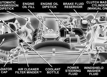
ENGINE COMPARTMENT
5.9L HO CUMMINS TURBO DIESEL
ONBOARD DIAGNOSTIC SYSTEM (OBD II) CARB emission control vehicles are equipped with a sophisticated onboard diagnostic system called OBDII. This system monitors the performance of the emissions, engine, and automatic transmission control systems. When these systems are operating properly, your vehicle will provide excellent performance and fuel economy, as well as engine emissions well within current government regulations. If any of these systems require service, the OBD II system will turn on the “Malfunction Indicator Light.” It will also store diagnostic codes and other information to assist your service technician in making repairs. Al- though your vehicle will usually be driveable and not need towing, see your dealer for service as soon as possible.
MAINTAINING YOUR VEHICLE 339
CAUTION!
Prolonged driving with the “Malfunction Indicator Light” on could cause further damage to the emis- sion control system. It could also affect fuel economy and driveability. The vehicle must be serviced before any emissions tests can be performed. If the “Malfunction Indicator Light” is flashing, severe catalytic converter damage and power loss will soon occur. Immediate service is required.
REPLACEMENT PARTS Use of genuine Mopar威 parts for normal/scheduled maintenance and repairs is highly recommended to in- sure the designed performance. Damage or failures caused by the use of non-Mopar parts for maintenance and repairs will not be covered by the manufacturer’s warranty.
340 MAINTAINING YOUR VEHICLE
DEALER SERVICE Your dealer has the qualified service personnel, special tools and equipment to perform all service operations in an expert manner. Service manuals are available which include detailed service information for your vehicle. Refer to these manuals before attempting any procedure yourself. NOTE: systems can result against you.
Intentional tampering with emissions control in civil penalties being assessed
WARNING!
You can be badly injured working on or around a motor vehicle. Do only that service work for which you have the knowledge and the proper equipment. If you have any doubt about your ability to perform a service job, take your vehicle to a competent mechanic.
SERVICE INFORMATION Mopar Fluids, Lubricants and Parts are available from your dealer and will help you keep your vehicle operat- ing at its best. Your dealer also has the qualified service personnel, special tools and equipment to perform all service operations in an expert manner. Service manuals are available which include detailed service information for your vehicle. Refer to these manuals before attempt- ing any procedure yourself. See Service Publications information at the back of this manual. NOTE: Failure to perform maintenance service at the specified intervals as outlined in the Maintenance Schedules may void provisions of your Vehicle Warranty.
CAUTION!
To maintain your vehicle safely follow these guide- lines: • Watch your vehicle’s mileage and check your Mainte- nance Schedules regularly for required servicing. Ex- cessive wear or damage to certain vehicle components can result if required services are not performed.
• If you have your vehicle undercoated,
inspect for undercoating material on the propeller shafts. Such material could cause the shafts to become unbalanced and result in drivetrain vibrations. Remove any under- coating with solvent. • If you have your vehicle undercoated, make sure no undercoating material is sprayed on the exhaust sys- tem or components of the seat belt system.
MAINTAINING YOUR VEHICLE 341
It is not possible for the manufacturer and NOTE: Cummins, Inc. to anticipate every possible circumstance that can involve a potential hazard.
WARNING!
To maintain your vehicle safely and avoid personal injury, follow these guidelines: • Never spray or pour diesel fuel, flammable liquid or starting fluids (ether) into the air cleaner canister, air intake piping or turbocharger inlet in an attempt to start the vehicle. • Do not use alcohol or gasoline as a fuel blending agent. They can be unstable under certain conditions and be hazardous or explosive when mixed with diesel fuel.
342 MAINTAINING YOUR VEHICLE
will stay hot after the engine is shut off.
• If an engine has been operating and the coolant is hot, allow the engine to cool before you slowly loosen the filler cap and relieve the pressure from the cooling system. • To avoid burns, remember that the engine components • Do not use gasoline or other flammable materials to clean parts. Always use approved cleaning solvents. • Relieve all pressure in the fuel, oil and cooling systems before any lines, fittings or related items are removed or disconnected. Be alert for possible pressure when disconnecting any device from a system that utilizes pressure. Do not check for pressure leaks with your hand. High pressure oil or fuel can cause personal injury.
WARNING!
Do not open the high pressure fuel system with the engine running. Engine operation causes high fuel pressure. High pressure fuel spray can cause serious injury or death. • Important: All maintenance other than that listed in this manual, as well as some procedures listed here, MUST be performed by your local Dodge Truck Dealer. Your authorized Dodge Dealer has been trained and has the necessary parts to maintain your engine.
MAINTAINING YOUR VEHICLE 343
engine, first ensure the engine is at full operating tem- perature, then wait at least 15 minutes after engine shutdown to check the oil. Checking the vehicle while it’s on level ground will also improve the accuracy of the oil level readings. Add oil only when the level on the dipstick is below the “ADD” mark. The total capacity from the low mark to the high mark is 2 quarts (1.9 liters).
MAINTENANCE PROCEDURES The pages that follow contain the required maintenance services determined by the engineers who designed your vehicle. Besides the maintenance items for which there are fixed maintenance intervals, there are other items that should operate satisfactorily without periodic maintenance. However, if a malfunction of these items does occur, it could adversely affect the engine or vehicle performance. These items should be inspected if a malfunction is observed or suspected. Engine Oil
Checking Oil Level To assure proper lubrication of your vehicle’s engine, the engine oil must be maintained at the correct level. Check the oil level at regular intervals. The best time to check the oil level is before starting the engine after it has been parked overnight. When checking oil after operating the
344 MAINTAINING YOUR VEHICLE
Never operate the engine with oil level below the “ADD” mark or above the upper “SAFE” mark. Change Engine Oil
CAUTION!
Overfilling or underfilling the crankcase will cause oil aeration or loss of oil pressure. This could dam- age your engine.
Road conditions as well as your kind of driving affect the interval at which your oil should be changed. Check the following to determine if any apply to you: • Frequent short trips where the engine does not achieve full operating temperature (operating temperature de- fined as 190° F (66° C) coolant temperature).
• Extensive engine idling (over 10 minutes per hour of operation) at ambient temperatures less than 32° F (0° C).
• Driving in dusty conditions. • Frequent trailer towing. • Taxi, police, or delivery service (commercial service). • Off-road or desert operation. • Extensive operation at high engine speeds (greater than 2900 rpm) and loads (greater than 70% throttle). If ANY of these apply to you, then change your engine oil at every interval shown in schedule ⬙B⬙ of the ⬙Mainte- nance Schedules⬙ section of this manual. If none of these apply to you, then change your engine oil at every interval shown on schedule ⬙A⬙ of the ⬙Mainte- nance Schedules⬙ section of this manual.
NOTE: Most vehicles are operated under the conditions listed for Schedule ⬙B.⬙ Engine Oil Selection
1. Engine Oil Quality
Use only oils conforming to API Ser- vice CI-4. A sulfated ash limit is speci- fied for lubrication oil used in Cum- mins engines. Oils with a high ash content may produce deposits on valves that can progress to guttering and valve burning. A maximum sul- fated ash content of 1.85 mass % is recommended for all oil used in the engine. 2. Engine Oil Viscosity (SAE Grade) The proper SAE viscosity of engine oil for the expected ambient temperature range should be selected, as indi- cated in the following chart:
MAINTAINING YOUR VEHICLE 345
NOTE: The same oil change interval is to be followed for synthetic oil as for petroleum based oil. Also, syn- thetic oil must meet the same performance specifications as petroleum oil.
346 MAINTAINING YOUR VEHICLE
Engine Oil Filter Refer to Recommended Fluids, Lubricants and Genuine Parts for the correct part number. The engine oil filter should be changed at every engine oil change. Engine Oil And Filter — Change
WARNING!
Hot oil can cause personal injury.
Operate the engine until the coolant temperature reaches 140°F (60°C). Shut the engine off. Remove the oil drain plug. Use a container that can hold at least 12 quarts (11.3
Liters) to hold the used oil.Always check the condition of the used oil. This can give you an indication of some engine problems that might exist. • Thin, black oil indicates fuel dilution. • Milky discoloration indicates coolant dilution. Clean the area around the oil filter base. Remove the filter from the underside of the vehicle using a cap style oil filter wrench. Clean the gasket surface of the filter mount. The filter gasket can stick on the filter mount. Make sure it is removed. Change the engine oil filter with every engine oil change. Only a high quality MOPAR filter should be used to assure most efficient service.
MAINTAINING YOUR VEHICLE 347
CAUTION!
CAUTION!
The filtering medium of other aftermarket filters may disintegrate. Debris from failed filters may plug the piston oil cooling nozzles, resulting in scuffed pistons and engine failure.
CAUTION!
Fill the oil filter element with clean oil before installation. Use the same type oil that will be used in the engine. When filling the oil filter, prevent foreign material from falling into the filter. Severe engine damage may occur.
Apply a light film of lubricating oil to the sealing surface of the filter gasket before installing the filter.
Overtightening may distort the threads or damage the filter element seal.
Install the filter as specified by the filter manufacturer. Turn the filter 3/4 to one full turn after making contact with the gasket. Check the condition of the threads and sealing surface on the oil pan and drain plug. Install the drain plug and sealing washer and tighten to 37 ft-lbs. (50 N·m). Use only high-quality multi-grade lubricating oil in your Cummins Diesel Engine. Choose the correct oil for your operating conditions as outlined in the Selection of Engine Oil.
348 MAINTAINING YOUR VEHICLE
Cummins Turbo Diesel Fill the engine with the correct grade of new oil. The engine capacity is 11 quarts (10.4 liters) in the crankcase and 1 quart (.95 liter) in the lubricating oil filter. Start the engine and operate it at idle for several minutes. Check for leaks at the lubricating oil filter and oil pan drain plug. Run the engine until it has reached operating tempera- ture, stop the engine. Wait approximately 15 minutes to let the oil in the upper parts of the engine drain back to the pan. Check the oil level again. Add oil as necessary to bring the level to the “SAFE” mark on the dipstick. Disposing Of Used Engine Oil And Filter Care should be taken in disposing of the used engine fluids from your vehicle. Used fluids, indiscriminately discarded, can present a problem to the environment.
Contact your local dealer, service station, or governmen- tal agency for advice on recycling programs and where used fluids and filters can be safely discarded in your area. Drive Belt
able.
Inspection Check the belt for intersecting cracks. • Transverse (across the belt width) cracks are accept- • Longitudinal (direction of belt length) cracks that intersect with transverse cracks are NOT acceptable. Replace the belt if it has unacceptable cracks, is frayed or has pieces of material missing. The engine speed sensor, located near the damper, should be inspected for damage if a belt is frayed.
Engine Air Cleaner Filter
CAUTION!
All air entering the engine intake must be filtered. The abrasive particles in unfiltered air will cause rapid wear to engine components.
The air filter housing on your Diesel Ram is equipped with a Filter Minder™. This is an air flow restriction gauge that will indicate when the filter element needs to be replaced. Do not remove the top of the air filter housing to inspect the filter element on your diesel engine under normal operating conditions.
MAINTAINING YOUR VEHICLE 349
The clear plastic housing on the Filter Minder™ allows you to view the amount of air pressure drop across the filter element. It consists of a diaphragm and a calibrated spring sealed inside the plastic housing. As the air cleaner filter becomes clogged and air pressure drop
350 MAINTAINING YOUR VEHICLE
across the filter element increases, a yellow disc travels along a graduated scale on the side of the Filter Minder™. The yellow disc will always show the greatest restriction experienced by the filter element. When the disc reaches the red zone, the filter element may need to be replaced. There is no other time or mileage interval for changing the air cleaner filter element. If the vehicle experiences a sudden loss of engine power when being driven in heavy snow or rain or when plowing snow, check the Filter Minder™ • If the Filter Minder™ is showing a plugged filter, the filter should be visually inspected for snow/ice build up or extreme water saturation. • The filter is not damaged, remove all snow/ice, rein-
stall filter and reset the Filter Minder™.
A visual inspection of the air cleaner filter element is never recommended under normal circumstances. A badly restricted element may appear clean while a soiled element may be quite effective in filtering particles without restricting air flow. Rely on the Filter Minder™ to determine when a filter change is necessary. After a new filter element is inserted, press the rubber button on the top of the Filter Minder™. This action will reset the yellow disc to the clean position.
CAUTION!
When using an engine cleaner or a degreaser, be sure to wrap and tape the Filter Minder™ to protect the plastic housing from damage and discoloration.
CAUTION!
CAUTION!
Many aftermarket performance air filter elements do not adequately filter the air entering the engine. Use of such filters can severely damage your engine.
Do not drain the fuel/water separator filter when the engine is running.
MAINTAINING YOUR VEHICLE 351
Draining Fuel/Water Separator Filter
Drain a small amount from the fuel/water separator filter periodically or when the WATER IN FUEL indicator lamp is on. Pull outward on the drain valve lever, located on the side of the filter, and allow any accumulated water to drain. Hold the drain valve open until all water and contaminants have been removed. Close the drain release valve, by returning it to the inward position, when clean fuel is visible. NOTE: The Fuel / Water separator drain valve is identified by its yellow handle and is located on the inboard side of the fuel filter housing.
352 MAINTAINING YOUR VEHICLE
If more than a couple ounces of fuel has been drained, follow the directions below for “Priming if the engine has run out of fuel.”
WARNING!
Do not open the high pressure fuel system with the engine running. Engine operation causes high fuel pressure. High pressure fuel spray can cause serious injury or death.
Priming if the engine has run out of fuel 1. Add a substantial quantity of fuel to the tank 5 to 10
gallons (19L to 38L). 2. Crank the engine for 1 to 2 seconds. If the engine does not start, then release the key or starter button back to the RUN position (do not turn the key back to the OFF position). The electric fuel transfer pump will continue torun and purge air from the system for about 25 seconds. After 25 seconds, attempt to start the engine again. 3. Start the engine using the Normal Starting Procedure. 4. Repeat the procedure if the engine does not start.
CAUTION!
Do not engage the starter motor for more than 15
seconds at a time. Allow two minutes between the cranking intervals.NOTE: The engine may run rough until the air is forced from all the fuel lines.
CAUTION!
CAUTION!
Diesel fuel will damage black top paving surfaces. Drain the filter into an appropriate container.
Due to lack of lubricants in alcohol or gasoline, the use of these fuels can cause damage to the fuel system.
MAINTAINING YOUR VEHICLE 353
WARNING!
Do not use alcohol or gasoline as a fuel blending agent. They can be unstable under certain conditions and be hazardous or explosive when mixed with diesel fuel.
NOTE: A maximum blend of 5% biodiesel may be used with your Cummins Diesel equipped Dodge Ram Truck NOTE: As sufficient testing as not been completed, ethanol blends are not recommended or approved for use with your Cummins Diesel equipped Dodge Ram Truck. In addition, commercially available fuel addi- NOTE: tives are not necessary for the proper operation of your Cummins Diesel equipped Dodge Ram Truck.
354 MAINTAINING YOUR VEHICLE
Maintenance Free Batteries The top of the maintenance free batteries are perma- nently sealed. You will never have to add water, nor is periodic maintenance required.
To determine the battery charge, check the battery test indicator (if equipped) on top of each battery. If the test indicator (if equipped) appears light or yellow, replace the battery.
NOTE: Replacement batteries should both be of equal capacity to prevent damage to the vehicle’s charging system.
CAUTION!
It is essential when replacing the cables on the battery that the positive cable is attached to the positive post and the negative cable is attached to the negative post. Battery posts are marked (+) positive and negative (-) and identified on the battery case. Also, if a “fast charger” is used while battery is in vehicle, disconnect both vehicle battery cables be- fore connecting the charger to battery. Do not use a “fast charger” to provide starting voltage.
WARNING!
Battery posts, terminals, and related accessories con- tain lead and lead compounds. Always wash hands after handling the battery.
Battery Blanket Usage A battery loses 60% of its cranking power as the battery temperature decreases to 0°F (-18°). For the same de- crease in temperature, the engine requires twice as much power to crank at the same RPM. The use of 120 VAC powered battery blankets will greatly increase starting capability at low temperatures. Suitable battery blankets are available from your authorized Mopar威 dealer.
MAINTAINING YOUR VEHICLE 355
Air Conditioner Maintenance For best possible performance, your air conditioner should be checked and serviced by an Authorized Dealer at the start of each warm season. This service should include cleaning of the condenser fins and a performance test. Drive belt tension should also be checked at this time.
356 MAINTAINING YOUR VEHICLE
WARNING!
• Use only refrigerants and compressor lubricants approved by the manufacturer for your air condi- tioning system. Some unapproved refrigerants are flammable and can explode, injuring you. Other unapproved refrigerants or lubricants can cause the system to fail, requiring costly repairs. Refer to Section 3 of the Warranty Information book for further warranty information. • The air conditioning system contains refrigerant under high pressure. To avoid risk of personal injury or damage to the system, adding refrigerant or any repair requiring lines to be disconnected should be done by an experienced repairman.
Refrigerant Recovery and Recycling R-134a Air Conditioning Refrigerant is a hydrofluorocar- bon (HFC) that is endorsed by the Environmental Pro- tection Agency and is an ozone-saving product. How- ever, the manufacturer recommends that air conditioning service be performed by dealers or other service facilities using recovery and recycling equipment. Power Steering — Fluid Check Checking the power steering fluid level at a defined service interval is not required. The fluid should only be checked if a leak is suspected, abnormal noises are apparent, and/or the system is not functioning as antici- pated. Coordinate inspection efforts through a certified DaimlerChrysler Dealership.⬙
WARNING!
Fluid level should be checked on a level surface and with the engine off to prevent injury from moving parts and to insure accurate fluid level reading. Do not overfill. Use only manufacturers recommended power steering fluid.
If necessary, add fluid to restore to the proper indicated level. With a clean cloth, wipe any spilled fluid from all surfaces. Refer to Recommended Fluids, Lubricants, and Genuine Parts for correct fluid type.
MAINTAINING YOUR VEHICLE 357
Front Suspension Ball Joints The ball joints originally supplied with the vehicle are permanently lubricated at the factory and do not require service. The ball joints and seals should be inspected whenever the vehicle is serviced for other reasons. Steering Linkage — Inspection Whenever the vehicle is hoisted, all steering linkage joints should be inspected for evidence of damage. If seals are damaged, parts should be replaced to prevent leakage or contamination of the grease.
358 MAINTAINING YOUR VEHICLE
Front Prop Shaft Lubrication Lubricate the front driveshaft grease fitting at each oil change listed in the appropriate Maintenance Schedule for your vehicle (Schedule “A” and “B”). Use Mopar威 type MS-6560 (lithium based grease), or equivalent.
Front Driveshaft Grease Fitting
Front Axle Universal Drive Joints And Pivot Bearings The front axle universal joint and pivot bearings are permanently lubricated and do not require servicing. Body Lubrication Locks and all body pivot points, including such items as seat tracks, doors,liftgate and hood hinges, should be lubricated periodically to assure quiet, easy operation and to protect against rust and wear. Prior to the appli- cation of any lubricant, the parts concerned should be wiped clean to remove dust and grit; after lubricating excess oil and grease should be removed. Particular attention should also be given to hood latching compo- nents to insure proper function. When performing other underhood services, the hood latch, release mechanism and safety catch should be cleaned and lubricated. The external lock cylinders should be lubricated twice a year, preferably in the fall and spring. Apply a small
amount of a high quality lubricant such as Mopar威 Lock Cylinder Lubricant directly into the lock cylinder. Windshield Wiper Blades The rubber edges of the wiper blades and the windshield should be cleaned periodically with a sponge or soft cloth and a mild nonabrasive cleaner. This will remove accu- mulations of salt or road film. Operation of the wipers on dry glass for long periods may cause deterioration of the wiper blades. Always use washer fluid when using the wipers to remove salt or dirt from a dry windshield. Avoid using the wiper blades to remove frost or ice from the windshield. Keep the blade rubber out of contact with petroleum products such as engine oil, gasoline, etc.
MAINTAINING YOUR VEHICLE 359
Windshield Washers The fluid reservoir is located under the hood and should be checked for fluid level at regular intervals. Fill the reservoir with windshield washer solvent only (not ra- diator antifreeze). To prevent freeze-up of your windshield washer system in cold weather, select a solution or mixture that meets or exceeds the temperature range of your climate. This rating information can be found on most washer fluid containers.
WARNING!
Commercially available windshield washer solvents are flammable. They could ignite and burn you. Care must be exercised when filling or working around the washer solution.
360 MAINTAINING YOUR VEHICLE
After the engine has warmed, operate the defroster for a few minutes to reduce the possibility of smearing or freezing the fluid on the cold windshield. Mopar All Weather Windshield Washer Solution, used with water as directed on the container, aids cleaning action, reduces the freezing point to avoid line clogging, and is not harmful to paint or trim. Exhaust System The best protection against carbon monoxide entry into the vehicle body is a properly maintained engine exhaust system. Whenever a change is noticed in the sound of the exhaust system, when exhaust fumes can be detected inside the vehicle, or when the underside or rear of the vehicle is damaged, have a competent mechanic inspect the com- plete exhaust system and adjacent body areas for broken, damaged, deteriorated, or mispositioned parts. Open seams or loose connections could permit exhaust fumes
to seep into the passenger compartment. In addition, inspect the exhaust system each time the vehicle is raised for lubrication or oil change. Replace as required.
WARNING!
Exhaust gases can injure or kill. They contain carbon monoxide (CO) which is colorless and odorless. Breathing it can make you unconscious and can eventually poison you. To avoid breathing CO, fol- low the preceding safety tips.
Exhaust System Rubber Isolator and Loop-Type Hanger — If Equipped Inspect surfaces whenever the vehicle is hoisted for rubber to metal separation or deep cracks. If, however, excessively deep localized cracks are present, or any part
of the exhaust system abnormally contacts the under- body hardware, the isolator and/or hanger should be replaced. Cooling System
Cooling System Maintenance At the intervals shown in the Maintenance Schedules Section of the manual, the system should be drained, flushed and filled. Inspection Check engine coolant (antifreeze) protection every 12
months (before the onset of freezing weather, where applicable). If coolant is dirty or rusty in appearance, the system should be drained, flushed and refilled with fresh coolant as specified. Inspect the entire cooling system for leaks. Check the face of the radiator for any accumulation of bugs, leaves, or other foreign matter. If dirty, clean the radiator core withMAINTAINING YOUR VEHICLE 361
a garden hose. With the engine OFF, gently spray water from the back of the radiator core. Check coolant bottle tube for condition and tightness of connections at coolant bottle and radiator. Extremely cold ambient temperature may require the addition of a “winter front” for effective operation of the cab heating/cooling system. Make certain that a percent- age of the radiator is exposed for adequate air flow through the charge air cooler and automatic transmission oil cooler. The percentage of opening must be increased with the increasing ambient air temperature and/or engine load. If the cooling fan can be heard cycling frequently, increase the size of the opening in the winter front. Coolant bottle level check The coolant reserve system provides a quick visual method of determining that the coolant level is adequate. With the engine idling, and warmed to the normal
362 MAINTAINING YOUR VEHICLE
operating temperature, the level of the coolant on the coolant bottle should be between the fluid level marks. Check the coolant level whenever the hood is raised. The radiator normally remains completely full, so there is no longer a need to remove the coolant pressure cap except for checking coolant freeze point or replacement with new antifreeze coolant.
WARNING!
Never add coolant to the radiator when the engine is overheated. Do not loosen or remove pressure cap to cool overheated engine! The coolant is under pres- sure and severe scalding could result.
Drain, Flush And Refill At intervals shown on the Maintenance Schedules, the system should be drained, flushed and refilled. Refer to your dealer or consult a service manual for proper procedures. Adding Coolant When adding coolant, or refilling the system, a minimum solution of 50% recommended HOAT ethylene glycol engine coolant (antifreeze) and distilled water should be used. Use higher concentrations (not to exceed 70%) if temperatures below ⫺34°F (⫺37°C) are anticipated. Use only high purity water such as distilled or deionized water when mixing the water/engine coolant solution. The use of lower quality water will reduce the amount of corrosion protection in the engine cooling system.
It is the owner’s responsibility to maintain the NOTE: proper level of protection against freezing according to the temperatures occurring in the area where the vehicle is operated. NOTE: Mixing coolant types will decrease the life of the engine coolant and will require more frequent coolant changes. When additional coolant is needed to maintain the proper level, add the recommended concentration of antifreeze and water to the overflow bottle. Do not overfill. NOTE: Failure to follow the antifreeze concentration and replacement recommendations, or failure to use antifreeze formulated to prevent corrosion of all cooling system metals, may result in radiator plugging, overheat- ing, or cooling system leaks such as in core hole plugs.
MAINTAINING YOUR VEHICLE 363
WARNING!
Never add coolant to the radiator when the engine is overheated. Do not loosen or remove pressure cap to cool an overheated engine. The coolant is under pressure and severe scalding could result.
Recommended Engine Coolant Refer to Recommended Fluids, Lubricants and Genuine Parts for the correct Fluid type.
364 MAINTAINING YOUR VEHICLE
CAUTION!
• Mixing of coolants other than specified engine coolant, may result in engine damage, and de- crease corrosion protection. If a non-HOAT cool- ant is introduced into the cooling system in an emergency, it should be replaced with the speci- fied coolant as soon as possible. • Do not use plain water alone or alcohol base engine coolant (antifreeze) products. Do not use additional rust inhibitors or antirust products, as they may not be compatible with the radiator engine coolant and may plug the radiator. • This vehicle has not been designed for use with Propylene Glycol based coolants. Use of Propy- lene Glycol based coolants is not recommended.
Disposal Of Used Engine Coolant Used ethylene glycol based engine coolant is a regulated substance requiring proper disposal. Check with your local authorities to determine the disposal rules for your community. Do not store ethylene glycol-based engine coolant in open containers or allow it to remain in puddles on the ground. Prevent ingestion by animals and children. If ingested by a child, contact a physician immediately. Clean up any ground spills immediately. Coolant Pressure Cap The coolant pressure cap must be fully tightened to prevent loss of coolant and to insure that coolant will return to the radiator from the coolant reserve tank.
WARNING!
Fan
MAINTAINING YOUR VEHICLE 365
Never add coolant when the engine is overheated. Do not loosen or remove the pressure cap to cool an overheated engine. Heat causes pressure build up in the cooling system. To prevent scalding or injury, do not remove the pressure cap while the system is hot or under pressure.
CAUTION!
Recheck the cooling system to insure total system is full of coolant.
Inspection Check the fan for cracks and bent or broken blades. If any of these conditions exist, you must replace the fan. Make sure it is securely mounted. NOTE: This service procedure must be performed by a trained service technician. Make arrangements with your authorized Dodge Truck Dealer for this inspection. Charge Air Cooler (Inter-Cooler) The charge air cooler is positioned between the radiator and the air conditioner condenser. Air enters the engine through the air cleaner and passes through the turbo- charger where it is pressurized. This pressurized air rapidly reaches high temperature. The air is then directed through a hose to the charge air cooler and through another hose to the intake manifold of the engine. The air entering the engine has been cooled by about 50 to 100
366 MAINTAINING YOUR VEHICLE
degrees Fahrenheit. This cooling process enables more efficient burning of fuel resulting in fewer emissions. To guarantee optimum performance of the system, keep the surfaces of the charge air cooler, condenser and radiator clean and free of debris. Periodically check the hoses leading to and from the charge air cooler for cracks or loose clamps resulting in loss of pressure and reduced engine performance. Hoses And Vacuum/Vapor Harnesses Inspect surfaces of hoses and nylon tubing for evidence of heat and mechanical damage. Hard or soft spots, brittle rubber, cracking, tears, cuts, abrasions, and exces- sive swelling indicate deterioration of the rubber. Pay particular attention to those hoses nearest to high heat sources such as the exhaust manifold. Inspect hose routing to be sure hoses do not come in contact with any heat source or moving component which may cause heat damage or mechanical wear.
Insure nylon tubing in these areas has not melted or collapsed. Inspect all hose connections such as clamps and cou- plings to make sure they are secure and no leaks are present. Components should be replaced immediately if there is any evidence of wear or damage that could cause failure. Brake System
Power Disc Brakes (Front and Rear) Disc brakes do not require adjustment; however, several hard stops during the break-in period are recommended to seat the linings and wear off any foreign material.
Brake Master Cylinder The fluid level of the master cylinder should be checked when performing under the hood service, or immedi- ately if the brake system warning lamp indicates system failure.
The brake master cylinder has a translucent plastic reservoir. On the outboard side of the reservoir, there is a
MAINTAINING YOUR VEHICLE 367
“FULL” dot and an “ADD” dot. The fluid level must be kept within these two dots. Do not add fluid above the full mark because leakage may occur at the cap. With disc brakes the fluid level can be expected to fall as the brake linings wear. However, an unexpected drop in fluid level may be caused by a leak and a system check should be conducted. Refer to Recommended Fluids, Lubricants and Genuine Parts for the correct Fluid type.
WARNING!
Use of a brake fluid that may have a lower initial boiling point, or unidentified as to specification, may result in sudden brake failure during hard prolonged braking. You could have an accident.
368 MAINTAINING YOUR VEHICLE
WARNING!
Overfilling the brake fluid reservoir can result in spilling brake fluid on hot engine parts and the brake fluid catching fire.
Use only brake fluid that has been in a tightly closed container to avoid contamination from foreign matter or moisture.
CAUTION!
Do not allow a petroleum-base fluid to contaminate the brake fluid. Seal damage and loss of brake performance may result.
Brake Hoses Inspection should be performed whenever the brake system is serviced or at intervals specified. Inspect hy- draulic brake hoses for surface cracking, scuffing or worn spots. If there is any evidence of cracking, scuffing, or worn spots, the hose should be replaced immediately! Eventual deterioration of the hose can take place with possible burst failure. Clutch Linkage If the clutch pedal linkage begins to squeak or grunt, the clutch pedal pivot bushings should be lubricated. Refer to Recommended Fluids, Lubricants and Genuine Parts for the correct type. Multipurpose Grease, NLGI Grade 2 E.P.
lubricant
Clutch Hydraulic System The clutch hydraulic system is a sealed maintenance-free system. In the event of leakage or other malfunction, the system must be replaced. Rear Axle And 4x4 Front Driving Axle Fluid Level For Model 9.25 Front Axles and 10.5”/11.5” Rear Axles refer to Recommended Fluids, Lubricants and Genuine Parts for the correct lubricant type. For normal service, periodic fluid level checks are not required. When the vehicle is serviced for other reasons, the exterior surfaces of the axle assembly should be inspected. When checking the fluid level, the vehicle should be in a level position. The fluid level should be 1/4” ± 1/4” (6.4
mm ± 6.4 mm) below the fill hole on the 9.25” Front Axle. The fluid level should be 3/4” ± 1/4” (19 mm ± 6.4 mm) below the fill hole on all 10.5” and 1/4” ± 1/4” (6.4 mm ± 6.4 mm) on 11.5” Rear Axles.MAINTAINING YOUR VEHICLE 369
Drain And Refill Vehicles operated in normal service do not have regularly scheduled oil changes. If fluid has become contaminated with water or subjected to severe service, follow the recommended change intervals in Maintenance Schedule “B” in Section 8 of this manual. Lubricant Selection Refer to Recommended Fluids, Lubricants and Genuine Parts for the correct lubricant type. NOTE: The presence of water in the gear lubricant will result in corrosion and possible failure of differential components. Operation of the vehicle in water, as may be encountered in some off-highway types of service, will require draining and refilling the axle to avoid damage. Limited-Slip Differentials in vehicles equipped with 10.5”/11.5” Axles DO NOT REQUIRE any limited slip oil additive (friction modifiers).
370 MAINTAINING YOUR VEHICLE
Transfer Case — If Equipped
Fluid Level Check This fluid level can be checked by removing the filler plug. The fluid level should be to the bottom edge of the filler plug hole with the vehicle in a level position. Lubricant Selection Refer to Recommended Fluids, Lubricants and Genuine Parts for the correct lubricant type. Manual Transmission — If Equipped
Fluid Level Check This fluid level can be checked by removing the filler plug. If the level of the lubricant is more than 1/4” below the bottom of the filler hole while the vehicle is on level ground, enough lubricant should be added to bring the level to the bottom of the filler hole.
Lubricant Selection for 6-Speed Manual Transmission — If Equipped If it becomes necessary to add fluid or change the fluid, be sure to use the same lubricant or equivalent. Refer to Recommended Fluids, Lubricants and Genuine Parts for the correct lubricant type. Automatic Transmission
Fluid Level Check The fluid level should be checked when the engine is fully warmed up and the fluid in the transmission is at normal operating temperature. Operation of the trans- mission with an improper fluid level will greatly reduce the life of the transmission and of the fluid. Check the fluid level whenever the vehicle is serviced.
Procedure For Checking Fluid Level To properly check the automatic transmission fluid level, the following procedure must be used: 1. The vehicle must be on level ground. 2. The engine should be running at curb idle speed for a minimum of 60 seconds. 3. Fully apply parking brake. 4. Place the gear selector briefly in each gear position ending with the lever in N (Neutral). 5. Remove the dipstick and determine if the fluid is hot or warm. Hot fluid is approximately 180°F (82°C) which is the normal operating temperature after the vehicle has been driven at least 15 miles. The fluid can not be comfortably held between the finger tips. Warm is when fluid is between 85° - 125°F (29° - 52°C).
MAINTAINING YOUR VEHICLE 371
6. Wipe the dipstick clean and reinsert until seated. Remove dipstick and note reading.
a. If the fluid is hot, the reading should be in the crosshatched area marked “OK”. b. If the fluid is warm, the reading should be between the two holes. If the fluid level indicates low, add sufficient fluid to bring to the proper level.
Fluid is added through the dipstick tube. NOTE: To prevent dirt and water from entering the transmission after checking or replenishing fluid, make certain that the dipstick cap is properly seated. Selection Of Lubricant Refer to Recommended Fluids, Lubricants and Genuine Parts for the correct lubricant type. It is important that the transmission fluid be maintained at the prescribed level using the recommended fluid.
372 MAINTAINING YOUR VEHICLE
CAUTION!
Using a transmission fluid other than the manufac- turers recommended fluid may cause deterioration in transmission shift quality and/or torque converter shudder. Using a transmission fluid other than the manufacturers recommended fluid will result in more frequent fluid and filter changes. Refer to Recommended Fluids, Lubricants and Genuine Parts for correct fluid type.
Automatic Transmission Fluid and Filter Change To obtain best performance and long life for automatic transmissions, the manufacturer recommends that they be given regular maintenance service by an Authorized Dodge Dealer or Service Center. It is important that the transmission be adjusted periodically, the fluid main- tained at the correct level, and that it be drained and refilled as specified.
It is important that proper lubricant is used in the transmission. Refer to Recommended Fluids, Lubricants and Genuine Parts for the correct lubricant type. A band adjustment and filter change should be made at the time of the oil change. The fluid and filter(s) should be changed and the bands adjusted (if equipped) ) as specified in the Maintenance Schedule (Section 8). Vehicles having severe usage should follow Maintenance Schedule “B” of the Maintenance Schedule (Section 8). Severe usage consists of: • Off-the-highway operation; • Trailer towing; • Snow plow operation; • Prolonged operation with heavy loading, especially in
hot weather.
If the transmission is disassembled for any NOTE: reason, the fluid and filter should be changed, and the bands adjusted (if equipped). Special Additives The manufacturer recommends against the addition of any additives to the transmission. Exception to this policy is the use of special dyes to aid in detecting fluid leaks. The use of transmission sealers should be avoided, since they may adversely affect seals. Front Wheel Bearings Front wheel bearings for all Dodge Ram Trucks are sealed-for-life. They do not require greasing or seal replacement. these bearings will “purge” excess grease and the bearing housing will look slightly wet. This is normal. • Periodic inspection for excess play is recommended.
In some instances,
MAINTAINING YOUR VEHICLE 373
• If a bearing assembly is accidentally separated when
servicing the brake rotors, it should be replaced.
Rear Wheel Bearings Clean and repack when brake linings are replaced or rotors resurfaced. Selection Of Lubricating Grease The National Lubricating Grease Institute (NLGI) has developed a symbol (Certification Mark) to aid the vehicle owner in the proper selection of grease for the lubrication of wheel bearings and chassis components. This symbol (an example shown below) is located on the grease container and identifies the application and qual- ity of the grease.
374 MAINTAINING YOUR VEHICLE
are
There two groups identified: those for wheel bearings (Letter “G”) and those for chassis (Letter “L”) lubrication. Perfor- mance categories within these groups result in dual letter for each group. The letter des- ignations shown in the ex- ample the highest quality level available and when combined as shown can be used for both wheel bearing and chassis lubrication. Use only those greases that have the NLGI symbol on the container along with the proper quality level for your application.
designations
are
Noise Control System Required Maintenance & Warranty For 3500 Two-Wheel Drive and Four-Wheel Drive mod- els over 10,000 lbs. (4 535 kg) Gross Vehicle Weight Rating. All vehicles built over 10,000 lbs. (4 535 kg) Gross Vehicle Weight Rating and manufactured for sale and use in the United States are required to comply with the Federal Government’s Exterior Noise Regulations. These vehicles can be identified by the Noise Emission Control Label located in the operator’s compartment.
MAINTAINING YOUR VEHICLE 375
or suspected. Proper maintenance of the entire vehicle will help the effectiveness of the noise control systems. Exhaust System Inspect the entire exhaust system for leaks and damaged parts. Devices such as hangers, clamps, and U-bolts should be tight and in good condition. Damaged compo- nents, burned or blown out mufflers, burned or rusted out exhaust pipes should be replaced according to the procedures and specifications outlined in the appropriate service manual. Air Cleaner Assembly Inspect air cleaner housing for proper assembly and fit. Make certain that the air cleaner is properly positioned and that the cover is tight. Check all hoses leading to the cleaner for tightness. The air filter element must also be clean and serviced according to the instructions outlined in the Maintenance Schedule Section of this manual.
Required Maintenance For Noise Control Systems The following maintenance services must be performed every 6 months or 6,000 miles (9 600 km), whichever comes first, to assure proper operation of the noise control systems. inspection and service should be performed anytime a malfunction is observed
In addition,
376 MAINTAINING YOUR VEHICLE
Tampering With Noise Control System Prohibited Federal law prohibits the following acts or the causing thereof: (1) the removal or rendering inoperative by any person, other than for purposes of maintenance, repair, or replacement, of any device or element of design incorpo- rated into any new vehicle for the purpose of noise control prior to its sale or delivery to the ultimate purchaser or while it is in use, or (2) the use of the vehicle after such device or element of design has been removed or rendered inoperative by any person. Among those acts presumed to constitute tampering are the acts listed below. • AIR CLEANER − Removal of the air cleaner. − Removal of the air cleaner filter element from the air
cleaner housing.
− Removal of the air ducting.
components including the muffler or tailpipe.
• EXHAUST SYSTEM − Removal or rendering inoperative exhaust system • ENGINE COOLING SYSTEM − Removal or rendering inoperative the fan clutch. − Removal of the fan shroud.
Noise Emission Warranty The manufacturer warrants that this vehicle as manufac- tured by the manufacturer, was designed, built and equipped to conform at the time it left the manufacturer’s control with all applicable U.S. EPA Noise Control Regu- lations. This warranty covers this vehicle as designed, built and equipped by the manufacturer, and is not limited to any particular part, component or system of the vehicle manufactured by the manufacturer. Defects in design,
MAINTAINING YOUR VEHICLE 377
emissions to exceed Federal standards, are covered by this warranty for the life of the vehicle.
assembly or in any part, component or system of the vehicle as manufactured by the manufacturer, which, at the time it left the manufacturer’s control, caused noise Maintenance Log and Service Chart — 24 Valve Cummins Turbo Diesel Noise Systems Maintenance Chart and Service Log — Insert Month, Day, Year under column mileage closest to the mileage at which service was performed. MILES KILOMETERS Exhaust system-inspect Air cleaner assembly-inspect ODOMETER READING PERFORMED BY PERFORMED AT
30,000
48 00037,500
60 00045,000
72 00060,000
96 0007,500
12 00022,500
36 00015,000
24 00052,500
84 000378 MAINTAINING YOUR VEHICLE
Noise Systems Maintenance Chart and Service Log — Insert Month, Day, Year under column mileage closest to the mileage at which service was performed. MILES KILOMETERS Exhaust system-inspect Air cleaner assembly-inspect ODOMETER READING PERFORMED BY PERFORMED AT
90,000
144 00097,500
126 00067,500
108 00082,500
132 00075,000
120 00084,000
156 000105,00
168 000112,500
181 000Appearance Care and Protection from Corrosion
Protection of Body and Paint from Corrosion Vehicle body care requirements vary according to geo- graphic locations and usage. Chemicals that make roads passable in snow and ice, and those that are sprayed on trees and road surfaces during other seasons, are highly corrosive to the metal in your vehicle. Outside parking, which exposes your vehicle to airborne contaminants, road surfaces on which the vehicle is operated, extreme hot or cold weather and other extreme conditions will have an adverse effect on paint, metal trim, and under- body protection. The following maintenance recommendations will enable you to obtain maximum benefit from the corrosion resistance built into your vehicle. What Causes Corrosion? Corrosion is the result of deterioration or removal of paint and protective coatings from your vehicle.
MAINTAINING YOUR VEHICLE 379
The most common causes are: • Road salt, dirt and moisture accumulation. • Stone and gravel impact. • Insects, tree sap and tar. • Salt in the air near seacoast localities. • Atmospheric fallout/industrial pollutants. Washing • Wash your vehicle regularly. Always wash your ve- hicle in the shade using a mild car wash soap, and rinse the panels completely with clear water.
NOTE: Fold the 7 x 10 inch trailer towing mirrors rearward prior to entering an automated car wash.
380 MAINTAINING YOUR VEHICLE
CAUTION!
CAUTION!
lated on your vehicle, wash it as soon as possible.
Do not attempt to fold the 7 x 10 inch trailer towing mirrors forward. The 7 x 10 inch trailer towing mirrors are not designed to be folded forward and doing so will damage the mirrors and/or vehicle. • If insects, tar or other similar deposits have accumu- • Use Mopar auto polish to remove road film and stains and to polish your vehicle. Take care never to scratch the paint. • Avoid using abrasive compounds and power buffing that may diminish the gloss or thin out the paint finish.
Do not use abrasive or strong cleaning materials such as steel wool or scouring powder, which will scratch metal and painted surfaces.
Special Care • If you drive on salted or dusty roads or if you drive near the ocean, hose off the undercarriage at least once a month. • It is important that the drain holes in the lower edges of the doors, rocker panels and tailgate be kept clear and open. • If you detect any stone chips or scratches in the paint, touch them up immediately. The cost of such repairs is considered the responsibility of the owner.
• If your vehicle is damaged due to an accident or similar cause which destroys the paint and protective coating have your vehicle repaired as soon as possible. The cost of such repairs is considered the responsibil- ity of the owner. • All wheels and wheel trim, especially aluminum and chrome plated wheels should be cleaned regularly with mild soap and water to prevent corrosion. To remove heavy soil, select a nonabrasive, non-acidic cleaner. Do not use scouring pads, steel wool, a bristle brush or metal polishes. Only Mopar cleaners are recommended. Do not use oven cleaner. Avoid auto- matic car washes that use acidic solutions or harsh brushes that may damage the wheels’ protective fin- ish. • If you carry special cargo such as chemicals, fertilizers, de-icer salt, etc., be sure that such materials are well packaged and sealed.
MAINTAINING YOUR VEHICLE 381
mud or stone shields behind each wheel.
• If a lot of driving is done on gravel roads, consider • Use Mopar touch up paint on scratches as soon as possible. Your dealer has touch up paint to match the color of your vehicle.
Interior Care Use Mopar Fabric Cleaner to clean fabric upholstery and carpeting. Use Mopar Vinyl Cleaner to clean vinyl upholstery and trim. Mopar Total Clean is specifically recommended for leather upholstery. Your leather upholstery can be best preserved by regular cleaning with a damp soft cloth. Small particles of dirt can act as an abrasive and damage the leather upholstery and should be removed promptly with a damp cloth. Stubborn soils can be removed easily with a soft cloth
382 MAINTAINING YOUR VEHICLE
and Mopar Total Clean. Care should be taken to avoid soaking your leather upholstery with any liquid. Please do not use polishes, oils, cleaning fluids, solvents, deter- gents, or ammonia based cleaners to clean your leather upholstery. Application of a leather conditioner is not required to maintain the original condition.
WARNING!
Do not use volatile solvents for cleaning purposes. Many are potentially flammable, and if used in closed areas they may cause respiratory harm.
Glass Surfaces All glass surfaces should be cleaned on a regular basis with any commercial household-type glass cleaner. Never use an abrasive type cleaner. Use caution when cleaning inside rear windows equipped with electric
defrosters or windshields equipped with a windshield wiper de-icer. Do not use scrapers or other sharp instru- ments which may scratch the elements. When cleaning the rear view mirror, spray cleaner on the towel or rag that you are using. Do not spray cleaner directly on the mirror. Cleaning Plastic Instrument Cluster Lenses The lenses in front of the instruments in this vehicle are molded in clear plastic. When cleaning the lenses, care must be taken to avoid scratching the plastic. 1. Clean with a wet soft rag. A mild soap solution may be used, but do not use high alcohol content or abrasive cleaners. If soap is used, wipe clean with a clean damp rag. 2. Dry with a soft tissue.
MAINTAINING YOUR VEHICLE 383
FUSE AND RELAY CENTER
Seat Belt Maintenance Do not bleach, dye or clean the belts with chemical solvents or abrasive cleaners. This will weaken the fabric. Sun damage will also weaken the fabric. If the belts need cleaning, use a mild soap solution or lukewarm water. Do not remove the belts from the car to wash them. Replace the belts if they appear frayed or worn or if the buckles do not work properly.
Your vehicle is equipped with a fuse and relay center located in the engine compartment near the battery. Located on the underside of the cover is a label that identifies each component. 1. Disconnect the battery negative (-) cables from the right and left batteries before removing the cover.
384 MAINTAINING YOUR VEHICLE
2. Use specified fuses only. 3. Always properly reinstall the cover.
VEHICLE STORAGE If you are storing your vehicle for more than 21 days, we recommend that you take the following steps to mini- mize the drain on your vehicle’s battery: • Disconnect the Ignition-Off Draw fuse (I.O.D.) fuse located in the Fuse and Relay Center, located in the engine compartment. The I.O.D. cavity includes a snap-in retainer that allows the fuse to be discon- nected, without removing it from the fuse block. • The electronic shift transfer case should be placed in the 4HI mode and kept in this position to minimize the battery drain. • As an alternative to the above steps you may, discon-
nect the negative cables from both batteries.
REPLACEMENT LIGHT BULBS
LIGHT BULBS — Inside Bulb No. Overhead Console Lights . . . . . . . . . . . . . . . TS 212-2
Dome Light. . . . . . . . . . . . . . . . . . . . . . . . . . . . 7679
All of the inside bulbs are brass or glass wedge base. Aluminum base bulbs are not approved.LIGHT BULBS — Outside Bulb No. Back-Up . . . . . . . . . . . . . . . . . . . . . . . . . . . . . . 3057
Center High Mounted Stop Lamp . . . . . . . . . . . . . 912
Fog Lamp . . . . . . . . . . . . . . . . . . . . . . . . . . . 9006LL Headlamp (Halogen) . . . . . . . . . . . . . . . . . . . 9007QL Park & Turn Signal . . . . . . . . . . . . . . . . . . . 3157NAK Rear License Plate Lamp . . . . . . . . . . . . . . . . . . . 168
Rear Cargo Light. . . . . . . . . . . . . . . . . . . . . . . . . 912
Tail & Stop . . . . . . . . . . . . . . . . . . . . . . . . . . . . 3057
Cab Clearance Lights . . . . . . . . . . . . . . . . . . . . . . 168
Dual Rear Wheel Sidemarker Light . . . . . . . . . . . . 168
Dual Rear Wheel Tailgate ID Lights (3) . . . . . . . . . 168BULB REPLACEMENT
Headlight (Halogen)/Front Park and Turn Lights
CAUTION!
This is a halogen bulb. Avoid touching the glass with your fingers. Reduced bulb life will result.
1. Remove the expanding fastener from the headlight welt.
MAINTAINING YOUR VEHICLE 385
386 MAINTAINING YOUR VEHICLE
2. Remove the three (3) bolts from the headlight housing. NOTE: The lower bolt on the driver side headlight also retains the ambient temperature sensor between the headlight assembly and the frame.
MAINTAINING YOUR VEHICLE 387
388 MAINTAINING YOUR VEHICLE
3. Pull the housing out from the fender to allow room to disconnect the electrical connectors.
4. Unlock and pull connector straight from the base of the headlight halogen bulb.
5. Twist connector on turn signal/park light bulb 1⁄4 turn and remove connector and bulb from housing. 6. Remove housing from vehicle with headlight halogen bulb in housing. 7. Twist collar on headlight halogen bulb 1⁄4 turn and remove headlight bulb from the housing. 8. Replace headlight or turn signal bulb. Do not touch the headlight halogen bulb. 9. Reverse procedure for installation of bulbs and hous- ing. 10. Tighten the outboard fastener first.
Tail, Stop, Turn and Backup Lights
1. Remove the two (2) screws that pass through the bed sheetmetal.
2. Pull the housing straight out from the body, with a quick motion, to separate the housing from the body. If not pulled straight, locators may be damaged.
MAINTAINING YOUR VEHICLE 389
3. Push the red lock slide in on the connector and remove the housing from the vehicle.
390 MAINTAINING YOUR VEHICLE
4. Remove the four (4) screws from the bulb strip in the housing.
5. Pull the appropriate bulb straight from the bulb strip.
• Top Bulb: Park/Turn/Hazard • Center Bulb: Stop/Park/Sidemarker • Bottom Bulb: Backup Lights
6. Reverse procedure for installation of bulbs and hous- ing. 7. While holding the taillight firmly in place, fasten the top screw first.
MAINTAINING YOUR VEHICLE 391
Center High-Mounted Stoplight With Cargo Light
1. Remove the two (2) screws holding the housing/lens to the body as shown.
392 MAINTAINING YOUR VEHICLE
2. Separate the connector holding the housing and wir- ing harness to the body.
4. Pull desired bulb straight from the socket.
3. Turn desired bulb socket 1⁄4 turn and remove socket and bulb from housing.
• Outside Bulbs: Cargo Lamps • Inside Bulb: Center High Mount Stop Lamp 5. Reverse procedure for installation of bulbs and hous- ing.