- 2009 Dodge RAM Diesel Owners Manuals
- Dodge RAM Diesel Owners Manuals
- 2010 Dodge RAM Diesel Owners Manuals
- Dodge RAM Diesel Owners Manuals
- 2005 Dodge RAM Diesel Owners Manuals
- Dodge RAM Diesel Owners Manuals
- 2006 Dodge RAM Diesel Owners Manuals
- Dodge RAM Diesel Owners Manuals
- 2008 Dodge RAM Diesel Owners Manuals
- Dodge RAM Diesel Owners Manuals
- 2004 Dodge RAM Diesel Owners Manuals
- Dodge RAM Diesel Owners Manuals
- 2007 Dodge RAM Diesel Owners Manuals
- Dodge RAM Diesel Owners Manuals
- Download PDF Manual
-
ACC Allows the electrical accessories to be used when the engine is not running. Manual Transmission Key Release Button
To remove the key on vehicles equipped with manual transmissions, turn the key to the Lock position and press the button to remove the ignition key.
Key Reminder An alarm will sound to remind you if the key is left in the ignition and the driver’s door is opened.
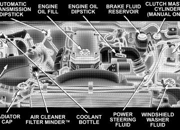
STARTING PROCEDURES The Cummins Diesel engine is equipped with several features designed to assist cold weather starting and operation: • The engine block heater is a resistance heater installed in the water jacket of the engine just above and behind the oil filter. It requires a 110–115 volt AC electrical outlet with a grounded, three-wire extension cord.
NOTE: The engine block heater cord is a factory in- stalled option. If your vehicle is not equipped, heater cords are available from your authorized Mopar威 dealer. • A 12–volt heater built into the fuel filter housing aids in preventing fuel gelling. It is controlled by a built-in thermostat.
• A heated intake air system both improves engine starting and reduces the amount of white smoke generated by a warming engine.
Normal Starting Procedure — Engine Manifold AirTemperature Above 66°F (19°C) Observe the Instrument Panel Cluster lights when start- ing the engine. 1. Always apply the parking brake. 2. Shift into PARK for an automatic transmission. Fully depress and hold the clutch and shift into NEUTRAL for a manual transmission. Models with manual transmis- sion are equipped with a clutch interlocking cranking system. The clutch must be fully depressed to start the vehicle. 3. Turn the ignition key to the ON position and look at the instrument panel cluster lamps.
STARTING AND OPERATING 225
The lamps in the instrument panel cluster will illuminate when the ignition key is first turned to the ON position. This is a bulb check programmed to last for approxi- mately 3 seconds. After the bulb check is completed, the Malfunction Indicator Light and Brake Warning light will remain on. After the bulb check is complete and the WAIT TO START indicator goes out proceed to step 4.
CAUTION!
If WATER IN FUEL indicator light remains on DO NOT START engine before you drain water from the fuel filter to avoid engine damage. See Section 7 — Maintaining Your Vehicle, for water drain proce- dures.
4. Turn the ignition key to START and crank the engine. Do not press the accelerator during starting.
226 STARTING AND OPERATING
CAUTION!
Do not crank engine for more than 15 seconds at a time as starter motor damage may result. Turn key to OFF and wait at least two minutes before trying again.
5. When the engine starts, release the key. 6. Check to see that there is oil pressure. 7. Release the parking brake. Starting Procedure — Engine Manifold Air Temperature Below 66°F (19°C)
NOTE: The temperature displayed on the overhead console (if equipped) does not necessarily reflect the engine manifold air temperature. The wait-to-start lamp will illuminate momentarily for a bulb check when the ignition key is turned to the ON position, however when
certain engine temperatures fall below 66°F (19°C) the lamp will remain on indicating the intake manifold heater system is active. Follow the steps in the Normal Starting Procedure ex- cept:
CAUTION!
Do not crank engine for more than 15 seconds at a time or starter motor damage may result. Turn key to OFF and wait at least 2 minutes for starter to cool before repeating start procedure. • The WAIT TO START light will remain on for a period of time (length of time depends on engine tempera- ture) after completion of the bulb check.
• After the WAIT TO START light goes off, turn the ignition key to START. Do not press the accelerator during starting. • Check to see that there is oil pressure. • Allow the engine to idle at fast idle for about three minutes until the manifold heaters have completed the post-heat cycle.
• Release the parking brake and drive. NOTE: Engine idle speed will automatically increase to 1000 rpm at low coolant temperatures to improve engine warm-up. If the engine stalls or if the ignition switch is left NOTE: On for more than 2 minutes after the WAIT TO START light goes out, reset the grid heaters by turning the ignition switch to Off for at least 5 seconds and then back On. Repeat steps 3 through 7 of the normal starting procedure.
STARTING AND OPERATING 227
For Extremely Cold Weather Starting — Engine Manifold Air Temperature Below 0°F (- 18°C) In extremely cold weather below 0°F (- 18°C) it may be beneficial to cycle the manifold heaters twice before attempting to start the engine. This can be accomplished by turning the ignition OFF for at least 5 seconds and then back ON after the WAIT TO START light has gone off, but before the engine is started. However, repeated cycling of the manifold heaters will result in damage to the heater elements or reduced battery voltage. NOTE: If multiple pre-heat cycles are used before starting, additional engine run time may be required to maintain battery state of charge at a satisfactory level. • If the engine stalls after the initial start, the ignition must be turned to the OFF position for at least 5
seconds and then to the ON position to recycle the manifold heaters.228 STARTING AND OPERATING
NOTE: Excessive white smoke and poor engine perfor- mance will result if manifold heaters are not recycled. • Heat generated by the manifold heaters dissipates rapidly in a cold engine. If more than two minutes pass between the time the WAIT TO START light goes OFF and the engine is started, recycle the manifold heaters by turning the ignition OFF for at least 5
seconds and then back ON. • If the vehicle is driven and vehicle speed exceeds 18
mph (29 km) before the manifold heater post-heat (after start) cycle is complete, the manifold heaters will shut off. • If the engine is started before the WAIT TO START • If the engine is cranked for more than 10 seconds, thelight turns off, the preheat cycle will turn off.
post-heat cycle will turn off.
NOTE: Engine idle speed will automatically increase to 1000 rpm at low coolant temperatures to improve engine warm-up. NOTE: When a diesel engine is allowed to run out of fuel or the fuel gels at low temperatures, air is pulled into the fuel system. You may try priming as described below. 1. Add a substantial quantity of fuel to the tank (5 to 10
gallons) or eliminate the gelled fuel condition. 2. Crank the engine for 1 to 2 seconds. If the engine does not start, then release the key or starter button back to the RUN position (do not turn the key back to the OFF position). The electric fuel transfer pump will continue to run and purge air from the system for about 25 seconds. After 25 seconds, attempt to start the engine again. 3. Start the engine using the Normal Starting Procedure.4. Repeat the procedure if the engine does not start.
Starting Fluids
STARTING AND OPERATING 229
WARNING!
WARNING!
Do not open the high pressure fuel system with the engine running. Engine operation causes high fuel pressure. High pressure fuel spray can cause serious injury or death.
NOTE: The engine may run rough until the air is forced from all the fuel lines.
STARTING FLUIDS or flammable liquids are NEVER TO BE USED in the Cummins Diesel (see Warning label). Never pour diesel fuel, flammable liquid, starting fluids (ether) into the air cleaner canister, air intake piping, or turbocharger inlet in an attempt to start the vehicle. This could result in a flash fire and explosion causing serious personal injury and engine damage.
The engine is equipped with an automatic electric air preheating system. If the instructions in this manual are followed, the engine should start in all conditions.
230 STARTING AND OPERATING
WARNING!
Do not leave children or animals inside parked vehicles in hot weather. Interior heat build up may cause serious injury or death.
NORMAL OPERATION Observe the following when the engine is operating. • All message center lights are off. • Check Engine Lamp is off. • Engine Oil Pressure is above 10 psi (69 kPa) at idle. • Low Oil Pressure light is off.
• Voltmeter Operation: • The voltmeter may show a gauge fluctuation if certain engine temperatures are below 66°F (19°C). This cycling operation is caused by the post-heat cycle of the intake manifold heater system. The number of cycles and the length of the cycling operation is controlled by the engine control mod- ule, this time will not exceed 150 seconds. The needle should then stabilize at the approximate operation point. • The cycling action will cause temporary dimming of the headlamps, interior lamps, and also a noticeable reduction in blower motor speed.
Cold Weather Precautions Operation in ambient temperature below 32°F (0°C) may require special considerations. The following charts sug- gest these options: Fuel Operating Range
*No. 1 diesel fuel should only be used where extended arctic conditions (-10°F/-23°C) exist. NOTE: • Use of Climatized Diesel Fuel or Number 1 Diesel Fuel
results in a noticeable decrease in fuel economy.
STARTING AND OPERATING 231
• Climatized Diesel Fuel is a blend of Number 2 and Number 1 Diesel Fuels which reduces the temperature at which wax crystals form in fuel.
NOTE: Refer to Fuel Requirements in this section for further details on fuel recommendations. Engine Block Heater The engine block heater warms engine coolant and permits quicker starts in cold weather. Connect the heater cord to a ground–fault interrupter protected 110–115 volt AC electrical outlet with a grounded, three-wire exten- sion cord. The engine block heater cord is routed under the hood to the right side and can be located just behind the grille near the headlamp. NOTE: The engine block heater cord is a factory in- stalled option. If your vehicle is not equipped, heater cords are available from your authorized Mopar威 dealer.
232 STARTING AND OPERATING
The block heater must be plugged in at least one hour to have an adequate warming effect on the coolant.
WARNING!
Remember to disconnect the cord before driving. Damage to the 110–115 volt electrical cord could cause electrocution.
NOTE: The block heater will require 110 Volts AC and 6.5 Amps to activate the heater element. Block Heater Usage A. Temperatures below 0°F (-18°C) • Block Heater Required for 15W-40
• Block Heater Recommended for 5W-40
B. Temperatures below - 20°F (-29°C) • Block Heater Required for 5W-40Winter Front Usage If a winter front or cold weather cover is to be used, a percentage of the total grille opening area must be left uncovered to provide sufficient air flow to the charge air cooler and automatic transmission oil cooler. The per- centage of opening must be increased with the increasing ambient air temperature and/or engine load. If the cooling fan can be heard cycling frequently, increase the size of the opening in the winter front. A suitable cold weather cover is available from your Mopar威 dealer. Battery Blanket Usage A battery loses 60% of its cranking power as the battery temperature decreases to 0°F (-18°). For the same de- crease in temperature, the engine requires twice as much power to crank at the same RPM. The use of 120 VAC powered battery blankets will greatly increase starting capability at low temperatures. Suitable battery blankets are available from your authorized Mopar威 dealer.
Arctic Operation Where there are no provisions to keep the engine warm when it is operating in ambient temperatures consistently below (-10°F/-23°C), use 5W-40 synthetic engine oil and fuel that meets the requirements in Section 7, “Mainte- nance Procedures,” Engine Oil Selection. Engine Warm-Up Avoid full throttle operation when the engine is cold. When starting a cold engine, bring the engine up to operating speed slowly to allow the oil pressure to stabilize as the engine warms up. NOTE: High-speed, no-load running of a cold engine can result in excessive white smoke and poor engine performance. No-load engine speeds should be kept under 1,200 rpm during the warm-up period, especially in cold ambient temperature conditions.
STARTING AND OPERATING 233
If temperatures are below 32°F (0°C), operate the engine at moderate speeds for 5 minutes before full loads are applied. Engine Idling — In Cold Weather Avoid prolonged idling in ambient temperatures below 0°F. Long periods of idling may be harmful to your engine because combustion chamber temperatures can drop so low that the fuel may not burn completely. Incomplete combustion allows carbon and varnish to form on piston rings and injector nozzles. Also, the unburned fuel can enter the crankcase, diluting the oil and causing rapid wear to the engine. NOTE: An optional driver-controlled high idle speed is available on automatic transmission equipped vehicles with speed control. This feature allows the driver to select an elevated idle speed between 1100 and 1500
rpms. Your dealer can enable this feature.234 STARTING AND OPERATING
NOTE: • If ambient
temperatures are low and the coolant temperature is below 200°F (93°C), the engine idle speed will slowly increase to 1000 RPM after 2 minutes of idle, if the following conditions are met: • foot is off brake pedal and throttle pedal • automatic transmission is in Park (P) • vehicle speed is zero • Applying the throttle will cancel fast idle • If the engine is equipped with an aftermarket exhaust brake (manual transmissions only), operating the ex- haust brake at idle will greatly improve warm up rate and will help keep the engine close to operating temperature during extended idle.
Stopping The Engine Idle the engine a few minutes before routine shutdown. After full load operation, idle the engine 3 to 5 minutes before shutting it down. This idle period will allow the lubricating oil and coolant to carry excess heat away from the combustion chamber, bearings, internal components, and turbocharger. This is especially important for turbo- charged, charge air cooled engines, like your Turbo Ram.
Driving Condition
Load
Turbocharger Temperature
Stop and Go
Empty
Cool
Stop and Go
Highway Speeds
Medium Medium
City Traffic Maximum
GCWR
Highway Speeds
Maximum
GCWR
Uphill Grade Maximum
GCWR
Warm
Hot
Idle Time
(min.) Before
Engine
Shutdown Less than
One One Two
Three
Four
Five
STARTING AND OPERATING 235
Engine Speed Control
CAUTION!
Prevent overspeeding the engine going down hill. When descending steep grades, use a combination of gears and service brakes to control vehicle/engine speed. Overspeed can cause severe engine damage.
Operating Precautions
Avoid Overheating The Engine The temperature of (a mixture of 50% the coolant ethylene-glycol and 50% water) must not exceed the normal range of the temperature gauge (240°F/116°C) with a 16 psi (110 kPa) radiator cap. Usually the coolant temperature indicated during opera- tion will be to the left of center in the normal range of the gauge.
236 STARTING AND OPERATING
Avoid Low Coolant Temperature Operation Continual operation at low coolant temperature below the normal range on the gauge (140°F/60°C) can be harmful to the engine. Low coolant temperature can cause incomplete combustion which allows carbon and varnish to form on piston rings and injector nozzles. Also, the unburned fuel can enter the crankcase, diluting the lubricating oil and causing rapid wear to the engine. Cooling System Tips — Automatic Transmission To reduce potential for engine and transmission over- heating in high ambient temperature conditions, take the following actions: • City Driving — when stopped, put transmission in neutral and increase engine idle speed. • Highway Driving — reduce your speed.
• Up Steep Hills — select a lower transmission gear, but try and keep the torque converter locked. • Air Conditioning — turn it off temporarily. Do Not Operate The Engine With Low Oil Pressure When the engine is at normal operating temperature, the minimum oil pressures required are: Idle 700 to 800 RPM . . . . . . . . . . . . 10 psi (69 kPa) Full speed and load . . . . . . . . . . . . 30 psi (207 kPa)
CAUTION!
If oil pressure falls to less than normal readings, shut the engine off immediately. Failure to do so could result in immediate and severe engine damage.
Do Not Operate The Engine With Failed Parts Practically all failures give some warning before the parts fail. Be on the alert for changes in performance, sounds, and visual evidence that the engine requires service. Some important clues are: • engine misfiring or vibrating severely • sudden loss of power • unusual engine noises • fuel, oil or coolant leaks • sudden change, outside the normal operating range, in • excessive smoke • oil pressure drop
the engine operating temperature
STARTING AND OPERATING 237
TRANSMISSION SHIFTING
Automatic Transmission with Overdrive— If Equipped The gear shift selector display, located in the instrument panel cluster, indicates the transmission gear range (the selector is illuminated for night driving). The selector lever is mounted on the right side of the steering column. You must depress the brake pedal, to pull the selector lever out of park (P) position (Brake Interlock System). To drive, move the selector lever from Park or Neutral to the desired drive position. Pull the selector lever toward you when shifting into Reverse, Second, First or Park, or when shifting out of Park. Gear Ranges DO NOT race the engine when shifting from Park or Neutral position into another gear range.
238 STARTING AND OPERATING
“P” Park This gear position supplements the parking brake by locking the transmission. The engine can be started in this range. Never use Park while the vehicle is in motion. Apply the parking brake when leaving the vehicle in this range. Always apply parking brake first, then place the selector in Park position. On 4-wheel drive vehicles be sure that the transfer case is in a drive position!
WARNING!
Your vehicle could move and injure you and others if it is not completely in P (Park). Check by trying to move the gearshift lever back and forth without first pulling it toward you after you have set it in P. Make sure it is in Park before leaving the vehicle.
WARNING!
It is dangerous to shift the selector lever out of “P” or “N” if the engine speed is higher than idle speed. If your foot is not firmly on the brake pedal, the vehicle could accelerate quickly forward or in re- verse. You could lose control of the vehicle and hit someone or something. Only shift into gear when the engine is idling normally and when your right foot is firmly on the brake pedal.
“R” Reverse Use this range only after the vehicle has come to a complete stop.
“N” Neutral Shift to Neutral when the vehicle is standing for pro- longed periods with the engine running. The engine may be started in this range. Set the parking brake if you must leave the vehicle. “D” Drive This position provides all forward gears, including 3rd gear direct and 4th or 5th (if equipped) gear overdrive (see Overdrive Operation). Use this range for most city and highway driving. “2” Second Use this position for driving slowly in heavy city traffic or on mountain roads where more precise speed control is desirable. Use it also when climbing long grades, and for engine braking when descending moderately steep grades. To prevent excessive engine speed do not exceed 45 mph (72 km/h) in this range.
STARTING AND OPERATING 239
“1” First Use this position for driving up very steep hills and for engine braking at low speeds 20 mph (32 km/h) or less when going downhill. To prevent excessive engine speed, do not exceed 25 mph (40 km/h) in this range. NOTE: Use caution when operating a heavily loaded vehicle in “2” Second or “1” First gear selections in high ambients as torque converter slip can impose significant additional heat load on the cooling system.
WARNING!
Never use Park position on an automatic transmis- sion as a substitute for the parking brake. Always apply parking brake fully when parked to guard against vehicle movement and possible injury or damage.
240 STARTING AND OPERATING
When To Use “TOW/HAUL” Mode
When driving in hilly areas, towing a trailer, carrying a heavy load, etc., and frequent transmission shifting oc- curs, press the “TOW/HAUL” button. This will improve performance and reduce the potential for transmission overheating or failure due to excessive shifting. When operating in “TOW/HAUL” mode, (if
5th gear
equipped) is disabled and 2-3 and 3-4 shift patterns are modified. Shifts into Overdrive (4th gear) are allowed during steady cruise (for improved fuel economy) and automatic closed-throttle downshifts to 3rd gear (for improved braking) will occur during steady braking. The “TOW/HAUL” light will illuminate in the instru- ment cluster to indicate when the switch has been activated. Pressing the switch a second time restores normal operation. If the “TOW/HAUL” mode is desired, the button must be pressed each time the engine is started. When To Lock Out Overdrive When driving in hilly areas, towing a trailer, carrying a heavy load, etc., and frequent 4–3–4 transmission shifting occurs, press the “TOW/HAUL” button. This will im- prove performance and reduce the potential for transmis- sion overheating or failure due to excessive shifting.
Torque Converter Clutch A feature, designed to improve fuel economy, has been included in the automatic transmission on your vehicle. A clutch within the torque converter engages automati- cally at calibrated speeds. This may result in a slightly different feeling or response during normal operation in high gear. When the vehicle speed drops or during acceleration when the transmission downshifts to second gear, the clutch automatically disengages. NOTE: The torque converter clutch will not engage until the transmission fluid and engine coolant are warm [usually after 1-3 miles (1.6 – 4.8 km) of driving]. Because the engine speed is higher when the torque converter clutch is not engaged, it may seem as if the transmission is not shifting into Overdrive when cold. This is normal. Pressing the “TOW/HAUL” button, when the transmis- sion is sufficiently warm, will demonstrate that the transmission is able to shift into and out of overdrive.
STARTING AND OPERATING 241
If the vehicle has not been driven in several NOTE: days, the first few seconds of operation after shifting the transmission into gear may seem sluggish. This is due to the fluid partially draining from the torque converter into the transmission. This condition is normal and will not cause damage to the transmission. The torque converter will refill within five seconds of shifting from Park into any other gear position. Manual Transmission — 6-Speed — If Equipped
NOTE: The parking brake should be engaged before leaving the vehicle, especially on an incline. Truck models with manual transmission are equipped with a clutch interlocking ignition system. The clutch pedal must be fully depressed to start the vehicle.
242 STARTING AND OPERATING
Fully depress the clutch pedal before shifting gears. As you release the clutch pedal, lightly depress the accelera- tor pedal. When launching a stationary vehicle, keep the engine speed low until the clutch is fully engaged. This transmission has a “creeper” 1st gear which should be used to start from a standing position when carrying a payload or towing a trailer. Damage to the clutch can result from starting in 2nd or 3rd gear with a loaded vehicle. Use each gear in numerical order – do not skip a gear. For steady highway driving with light acceleration, 6th gear is recommended. When shifting from 4th to 5th gear, apply side effort away and forward without pushing hard enough to engage Reverse gear. Shifting from 5th to 6th requires the same side effort or the lever will return to center resulting in a shift into 4th gear and damage the transmission, clutch, or engine.
You should use low gear when starting from a standing position if under a heavy load. To shift into Reverse, come to a complete stop. Depress the clutch and pause briefly to allow the gear train to stop. Move the shift lever from the Neutral position straight across and up into Reverse. Never drive with your foot resting on the clutch pedal, or attempt to hold the vehicle on a hill with the clutch pedal partially engaged, as this will cause abnormal wear on the clutch. Downshifting Moving from a high gear down to a lower gear is recommended to preserve brakes when driving down steep hills. In addition, downshifting at the right time provides better acceleration when you desire to resume speed. Downshift progressively. Do not skip gears to
avoid overspeeding the engine and clutch. For accelera- tion at speeds less than 15 mph (25 km/h), 2nd gear is recommended.
CAUTION!
When descending a hill, be very careful to downshift one gear at a time to prevent overspeeding the engine which can cause valve damage.
FOUR-WHEEL- DRIVE OPERATION — IF EQUIPPED • Four-Wheel-Drive Dodge Ram Trucks are equipped with either a Manually Shifted transfer case or an Electronically Shifted transfer case. See the operating instructions for your transfer case, located within this section.
STARTING AND OPERATING 243
Manually Shifted Transfer Case Operating Information/Precautions The transfer case provides 4 mode positions - 2 (rear)- wheel-drive high range, 4-wheel-drive high range, neu- tral, and 4-wheel-drive low range. This transfer case is intended to be driven in the 2-wheel- drive position (2H) for normal street and highway con- ditions such as dry hard surfaced roads. When additional traction is required the transfer case 4H and 4L positions can be used to lock the front and rear driveshafts together and force the front and rear wheels to rotate at the same speed. This is accomplished by simply moving the shift lever to the desired positions. The 4H and 4L positions are intended for loose, slippery road surfaces only. Driving in the 4H and 4L positions on dry hard surfaced roads may cause increased tire wear and damage to the driveline components.
244 STARTING AND OPERATING
The 4-wheel-drive light (4WD), located in the instrument cluster, alerts the driver that the vehicle is in 4-wheel drive and that the front and rear driveshafts are locked together. This light illuminates when the transfer case is shifted to either the 4H or 4L positions. There is no light for the 2H or N (Neutral) positions. When operating your vehicle in 4L, the engine speed is approximately three times that of the 2H or 4H positions at a given road speed. Take care not to overspeed the engine and do not exceed 25 mph (40 km/h). Proper operation of 4-wheel-drive vehicles depends on tires of equal size, type and circumference on each wheel. Any difference will adversely affect shifting and can cause damage to the transfer case.
NOTE: Do not attempt to make a shift while only the front or rear wheels are spinning. The transfer case is not equipped with a synchronizer and therefore the front and rear driveshaft speeds must be equal for the shift to take place. Shifting while only the front or rear wheels are spinning can cause damage to the transfer case. Because 4-wheel drive provides improved traction, there is a tendency to exceed safe turning and stopping speeds. Do not go faster than road conditions permit. NOTE: Delayed shifts out of four-wheel drive may be experienced due to uneven tire wear, low or uneven tire pressures, excessive vehicle loading, or cold tempera- tures.
WARNING!
You or others could be injured if you leave the vehicle unattended with the transfer case in the Neutral (N) position without first fully engaging the parking brake. The transfer case Neutral (N) position disengages both the front and rear driveshafts from the powertrain and will allow the vehicle to move regardless of the transmission position. The parking brake should always be applied when the driver is not in the vehicle.
For additional information on the appropriate use of each transfer case mode position see the information below: 2H Rear Wheel Drive High Range - Normal street and highway driving. Dry hard surfaced roads.
STARTING AND OPERATING 245
4H 4-Wheel-Drive High Range - Locks the front and rear driveshafts together. Forces the front and rear wheels to rotate at the same speed. Additional traction for loose, slippery road surfaces only. Neutral - Disengages both the front and rear driveshafts from the powertrain. To be used for flat towing behind another vehicle. See Recreational Towing for more infor- mation. 4L 4-Wheel-Drive Low Range - Low speed 4-wheel-drive. Locks the front and rear driveshafts together. Forces the front and rear wheels to rotate at the same speed. Additional traction and maximum pulling power for loose, slippery road surfaces only. Do not exceed 25 mph (40 km/h).
246 STARTING AND OPERATING
Shifting Procedure - Manually Shifted Transfer Case
2H ⇔ 4H Shifting between 2H and 4H can be made with the vehicle stopped or in motion. If the vehicle is in motion, shifts can be made up to 55 mph (88 km/h). With the
vehicle in motion, the transfer case will engage / disen- gage faster if you momentarily release the accelerator pedal after completing the shift. Apply a constant force when shifting the transfer case lever. 2H or 4H ⇔ 4L With the vehicle rolling at 2 to 3 mph (3 to 5 km/h), shift an automatic transmission to N (Neutral) or depress the clutch on a manual transmission. While the vehicle is coasting at 2 to 3 mph (3 to 5 km/h), shift the transfer case lever firmly to the desired position. Do not pause in transfer case N (Neutral). NOTE: Pausing in transfer case N (Neutral) in vehicles equipped with an automatic transmission may require shutting the engine OFF to avoid gear clash while completing the shift. If difficulty occurs, shift automatic transmission to N (Neutral), hold foot on brake, and turn engine OFF. Make shift to the desired mode.
NOTE: Shifting into or out of 4L is possible with the vehicle completely stopped, however difficulty may oc- cur due to the mating clutch teeth not being properly aligned. Several attempts may be required for clutch teeth alignment and shift completion to occur. The pre- ferred method is with the vehicle rolling 2 to 3 mph (3 to 5 km/h). Avoid attempting to engage or disengage 4L with the vehicle moving faster than 2 to 3 mph (3 to 5
km/h). NOTE: Do not attempt to shift to or from 4L while the transmission is in gear or clutch is engaged. Transfer Case Reminder Light The four-wheel-drive operating light (4WD), located in the instrument cluster, is used to alert the driver that the front axle is fully engaged and all four wheels are driving.STARTING AND OPERATING 247
Electronically Shifted Transfer Case Operating Information/Precautions This is an electric shift transfer case and is operated by the 4WD Control Switch (Transfer Case Switch), which is located on the instrument panel. The Electronically Shifted transfer case provides 4 mode positions: 2 (rear) wheel drive high range or all wheel drive high range, 4 wheel drive high range, 4 wheel drive low range, and neutral. The Electronically Shifted transfer case is designed to be driven in the 2 wheel drive position (2WD) or all wheel drive position (AWD) for normal street and highway conditions (dry hard surfaced roads). When additional traction is required, the transfer case 4HI and 4LO positions can be used to lock the front and rear driveshafts together and force the front and rear wheels to rotate at the same speed. This is accomplished by rotating the 4WD Control Switch to the desired
248 STARTING AND OPERATING
position - see Shifting Procedure section for specific shifting instructions. The 4HI and 4LO positions are designed for loose, slippery road surfaces only. Driving in the 4HI and 4LO positions on dry hard surfaced roads may cause increased tire wear and damage to the driv- eline components. NOTE: The transfer case Neutral (N) position is selected by depressing the recessed button located on the lower left hand corner of the 4WD Control Switch. The transfer case Neutral (N) position is to be used for recreational towing only. See the Recreational Towing section for specific procedures on shifting into and out of Neutral (N). Transfer Case Position Indicator Lights — Electronically Shifted Transfer Case Only Transfer case position indicator lights are located on the Four-Wheel-Drive Control Switch, found on your instru- ment panel, and indicate the current and desired transfer
case selection. When you select a different transfer case position, the indicator lights will do the following: If All Shift Conditions are Met 1. The current position indicator light will turn OFF. 2. The selected position indicator light will flash until the transfer case completes the shift. 3. When the shift is complete, the indicator light for the selected position will stop flashing and remain ON. If One or More Shift Conditions are not Met 1. The indicator light for the current position will remain ON. 2. The newly selected position indicator light will con- tinue to flash. 3. The transfer case will not shift.
NOTE: Before retrying a selection, make certain that all the necessary requirements for selecting a new transfer case position have been met. To retry the selection, turn the control knob back to the current position, wait five (5) seconds, and retry selection. To find the shift require- ments, refer to the ⬙Shifting Procedure⬙ for your transfer case, located in this section of the owner’s manual. The “SERVICE 4WD” warning light monitors the electric shift 4WD system. If this light remains on after engine start up or illuminates during driving, it means that the 4WD system is not functioning properly and that service is required.
STARTING AND OPERATING 249
WARNING!
Always engage the parking brake when powering down the vehicle if the ⴖService 4WDⴖ light is illuminated. Not engaging the parking brake may allow the vehicle to roll which may cause personal injury.
NOTE: Do not attempt to make a shift while only the front or rear wheels are spinning. The transfer case is not equipped with a synchronizer and therefore the front and rear driveshaft speeds must be equal for the shift to take place. Shifting while only the front or rear wheels are spinning can cause damage to the transfer case.
250 STARTING AND OPERATING
When operating your vehicle in 4LO, the engine speed is approximately three times that of the 2WD/AWD or 4HI positions at a given road speed. Take care not to over- speed the engine and do not exceed 25 mph (40 km/h). Proper operation of 4 wheel drive vehicles depends on tires of equal size, type and circumference on each wheel. Any difference in tire size can cause damage to the transfer case. Because 4 wheel drive provides improved traction, there is a tendency to exceed safe turning and stopping speeds. Do not go faster than road conditions permit.
WARNING!
You or others could be injured if you leave the vehicle unattended with the transfer case in the Neutral (N) position without first fully engaging the parking brake. The transfer case Neutral (N) position disengages both the front and rear driveshafts from the powertrain and will allow the vehicle to move regardless of the transmission position. The parking brake should always be applied when the driver is not in the vehicle.
STARTING AND OPERATING 251
Neutral - Disengages both the front and rear driveshafts from the powertrain. To be used for flat towing behind another vehicle. See Recreational Towing for more infor- mation. Shifting Procedure - Electronically Shifted Transfer Case
For additional information on the appropriate use of each transfer case mode position see the information below: 2WD/AWD Rear Wheel Drive High Range - Normal street and highway driving. Dry hard surfaced roads. 4HI 4 Wheel Drive High Range - Locks the front and rear driveshafts together. Forces the front and rear wheels to rotate at the same speed. Additional traction for loose, slippery road surfaces only. 4LO 4 Wheel Drive Low Range - Low speed 4 wheel drive. Locks the front and rear driveshafts together. Forces the front and rear wheels to rotate at the same speed. Additional traction and maximum pulling power for loose, slippery road surfaces only. Do not exceed 25 mph (40 km/h).
252 STARTING AND OPERATING
If any of the requirements to select a new NOTE: transfer case position have not been met, the transfer case will not shift.The indicator light for the previous position will remain ON and the newly selected position indicator light will continue to flash until all the requirements for the selected position have been met. To retry a shift:
return the control knob back to the original position, make certain all shift requirements have been met, wait five (5) seconds and try the shift again. If all the requirements to select a new transfer NOTE: case position have been met, the current position indica- tor light will turn OFF, the selected position indicator light will flash until the transfer case completes the shift. When the shift is complete, the indicator light for the selected position will stop flashing and remain ON. 2WD/AWD ⇔ 4HI Rotate the 4WD Control Switch to the desired position. Shifts between 2WD/AWD and 4HI can be done with the vehicle stopped or in motion. With the vehicle in motion, the transfer case will engage / disengage faster if you momentarily release the accelerator pedal after turning the control switch. If the vehicle is stopped, the ignition
key must be in the ON position with the engine either RUNNING or OFF. This shift cannot be completed if the key is in the accessory position. NOTE: The 4x4 system will not allow shifts between (2WD/AWD)/4HI if the front and/or rear wheels are spinning (no traction). In this situation the selected position indicator light will flash and the original posi- tion indicator light will remain ON. At this time, reduce speed and stop spinning the wheels to complete the shift. 2WD/AWD or 4HI ⇔ 4LO NOTE: When shifting into or out of 4LO some gear noise may be heard. This noise is normal and is not detrimental to the vehicle or occupants. Shifting can be performed with the vehicle rolling 2 to 3
mph (3 to 5 km/h) or completely stopped. USE EITHER OF THE FOLLOWING PROCEDURES:STARTING AND OPERATING 253
Preferred Procedure 1. With engine RUNNING, slow vehicle to 2 to 3 mph (3
to 5 km/h). 2. Shift the transmission into NEUTRAL (depress clutch on manual transmissions). 3. While still rolling, rotate the transfer case control switch to the desired position. 4. After the desired position indicator light is ON (not flashing), shift transmission back into gear (release clutch on manual transmissions). Alternate Procedure 1. Bring the vehicle to complete stop. 2. With the key ON and the engine either OFF or RUNNING, shift the transmission into NEUTRAL (de- press clutch on manual transmissions).254 STARTING AND OPERATING
3. Rotate the transfer case control switch to the desired position. 4. After the desired position indicator light is ON (not flashing), shift transmission back into gear (release clutch on manual transmissions). If steps 1 or 2 of either the Preferred or Alternate NOTE: Procedure are not satisfied prior to attempting the shift or if they no longer are being met while the shift attempt is in process then the desired position indicator light will flash continuously while the original position indicator light is ON, until all requirements have been met. NOTE: The ignition key must be ON for a shift to take place and for the position indicator lights to be operable. If the key is not ON then the shift will not take place and no position indicator lights will be on or flashing. NOTE: than 21 days, refer to the section on “Vehicle Storage.”
If your are leaving your vehicle stored for longer
LIMITED-SLIP DIFFERENTIAL — IF EQUIPPED The limited-slip differential provides additional traction on snow, ice, mud, sand and gravel, particularly when there is a difference between the traction characteristics of the surface under the right and left rear wheels. During normal driving and cornering, the limited-slip unit per- forms similarly to a conventional differential. On slip- pery surfaces, however, the differential delivers more of the driving effort to the rear wheel having the better traction. The limited-slip differential is especially helpful during slippery driving conditions. With both rear wheels on a slippery surface, a slight application of the accelerator will supply maximum traction. When starting with only one rear wheel on an excessively slippery surface, slight momentary application of the parking brake may be necessary to gain maximum traction.
WARNING!
On vehicles equipped with a limited-slip differen- tial, never run the engine with one rear wheel off the ground, since the vehicle may drive through the rear wheel remaining on the ground. You could lose control of the vehicle.
Care should be taken to avoid sudden accelerations when both rear wheels are on a slippery surface. This could cause both rear wheels to spin, and allow the vehicle to slide sideways on the crowned surface of a road or in a turn.
PARKING BRAKE The foot operated parking brake is positioned below the lower left corner of the instrument panel. To release the parking brake, pull the parking brake release handle.
STARTING AND OPERATING 255
NOTE: The instrument cluster red brake warning light will come on and flash to indicate that the parking brake is applied. You must be sure that the parking brake is fully applied before leaving the vehicle.
Be sure the parking brake is firmly set when parked and the gear shift lever is in the PARK position. When parking on a hill you should apply the parking brake before placing the gear shift lever in PARK, otherwise the
256 STARTING AND OPERATING
load on the transmission locking mechanism may make it difficult to move the selector out of PARK.
WARNING!
• Always fully apply the parking brake when leaving your vehicle, or it may roll and cause damage or injury. Also be certain to leave an automatic trans- mission in Park, a manual transmission in Reverse or first gear. Failure to do so may allow the vehicle to roll and cause damage or injury. • Leaving children in a vehicle unattended is danger- ous for a number of reasons. A child or others could be injured. Children should be warned not to touch the parking brake or the gear selector lever. Don’t leave the keys in the ignition. A child could operate power windows, other controls, or move the vehicle. • Be sure the parking brake is fully disengaged before driving, failure to do so can lead to brake problems due to excessive heating of the rear brakes.
When parking on a hill, turn the front wheels toward the curb on a downhill grade and away from the curb on an uphill grade. The parking brake should always be applied whenever the driver is not in the vehicle.
BRAKE SYSTEM If power assist is lost for any reason (for example, repeated brake applications with the engine off), the brakes will still function. However, you will experience a substantial increase in braking effort to stop the vehicle. If either the front or rear hydraulic systems lose normal capability, the remaining system will still function with some loss of overall braking effectiveness. This will be evident by increased pedal travel during application, greater pedal force required to slow or stop, and activa- tion of the BRAKE warning lamp and the ABS lamp (if equipped) during brake use.
Brake Noise During normal operation of the brake system certain noises may be present from time to time. Occasional ⬙groan⬙ or ⬙squeal⬙ noises may occur during normal operation of the brake system which may not be indica- tive of a problem. These noises may be heard at any time the brakes are applied but may be more noticeable during the first few brake applications in the morning. Moisture, hot or cold temperature, dust, and or other debris may also contribute to the noise condition. Repeated or con- tinuous noises during braking may be an indication that the brake linings are worn and in need of replacement.
STARTING AND OPERATING 257
Four-Wheel Anti-Lock Brake System
WARNING!
Anti-Lock Brake Systems contain sophisticated elec- tronic equipment. It may be susceptible to interfer- ence caused by improperly installed or high output radio transmitting equipment. This interference can cause possible loss of anti-lock braking capability. Installation of such equipment should be performed by qualified professionals.
258 STARTING AND OPERATING
WARNING!
• Anti-lock system (ABS) cannot prevent the natu- ral laws of physics from acting on the vehicle, nor can it increase braking or steering efficiency be- yond that afforded by the condition of the vehicle brakes and tires or the traction afforded.
• The ABS cannot prevent accidents,
including those resulting from excessive speed in turns, following another vehicle too closely, or hydro- planing. Only a safe, attentive, and skillful driver can prevent accidents. • The capabilities of an ABS equipped vehicle must never be exploited in a reckless or dangerous manner which could jeopardize the user’s safety or the safety of others.
This Anti-lock Brake System is designed to aid the driver in maintaining vehicle control under adverse braking conditions. The system operates with a separate com- puter to modulate hydraulic pressure to prevent wheel lockup and help avoid skidding on slippery surfaces. The system’s pump motor runs during an ABS stop to provide regulated hydraulic pressure. The pump motor makes a low humming noise during operation. This is normal. When you are in a severe braking condition involving use of the Anti-lock Brake System, you will experience some pedal drop as the vehicle comes to a complete stop. This is the result of the system reverting to the base brake system and is normal. Engagement of the Anti-lock Brake System may be accompanied by a pulsing sensation. You may also hear a clicking noise. These occurrences are normal, and indi- cate that the system is functioning.
ABS Warning Light The Anti-lock Brake System includes an amber warning light, located in the instrument cluster. When the light is illuminated, the Anti-lock Brake System is not function- ing. The system reverts to standard non-anti-lock brakes.
WARNING!
Pumping of the anti-lock brakes will diminish their effectiveness and may lead to an accident. Pumping makes the stopping distance longer. Just press firmly on your brake pedal when you need to slow down or stop.
STARTING AND OPERATING 259
POWER STEERING Your power steering system will provide mechanical steering capability if power assist is lost. If for any reason the hydraulic pressure is interrupted, it will still be possible to steer your vehicle. Under these conditions you will experience a substantial increase in steering effort.
260 STARTING AND OPERATING
TIRE SAFETY INFORMATION
Tire Markings
NOTE: • P(Passenger)-Metric tire sizing is based on U.S. design standards. P-Metric tires have the letter “P” molded into the sidewall preceding the size designation. Ex- ample: P215/65R15 95H.
• European Metric tire sizing is based on European design standards. Tires designed to this standard have the tire size molded into the sidewall beginning with the section width. The letter ⬙P⬙ is absent from this tire size designation. Example: 215/65R15 96H • LT(Light Truck)-Metric tire sizing is based on U.S. design standards. The size designation for LT-Metric tires is the same as for P-Metric tires except for the letters “LT” that are molded into the sidewall preced- ing the size designation. Example: LT235/85R16. • Temporary Spare tires are high pressure compact spares designed for temporary emergency use only. Tires designed to this standard have the letter “T” molded into the sidewall preceding the size designa- tion. Example: T145/80D18 103M. • High Flotation tire sizing is based on U.S. design standards and begins with the tire diameter molded into the sidewall. Example: 31x10.5 R15 LT.
Tire Sizing Chart
Size Designation:
EXAMPLE:
P = Passenger car tire size based on U.S. design standards ⴖ....blank....ⴖ = Passenger car tire based on European design standards LT = Light Truck tire based on U.S. design standards T = Temporary Spare tire 31 = Overall Diameter in Inches (in) 215 = Section Width in Milimeters (mm) 65 = Aspect Ratio in Percent (%)
—Ratio of section height to section width of tire.
10.5 = Section Width in Inches (in) R = Construction Code
—⬙R⬙ means Radial Construction. —⬙D⬙ means Diagonal or Bias Construction.
15 = Rim Diameter in Inches (in)
STARTING AND OPERATING 261
262 STARTING AND OPERATING
Service Description:
95 = Load Index
EXAMPLE:
—A numerical code associated with the maximum load a tire can carry.
H = Speed Symbol
—A symbol indicating the range of speeds at which a tire can carry a load corresponding to its load index under certain operating conditions. —The maximum speed corresponding to the Speed Symbol should only be achieved un- der specified operating conditions. (ie. tire pressure, vehicle loading, road conditions and posted speed limits).
Load Identification:
ⴖ....blank....ⴖ = Absence of any text on sidewall of the tire indicates a Standard Load (SL) Tire Extra Load (XL) = Extra Load (or Reinforced) Tire Light Load = Light Load Tire C,D,E = Load range associated with the maximum load a tire can carry at a specified pressure
Maximum Load — Maximum Load indicates the maximum load this tire is designed to carry. Maximum Pressure — Maximum Pressure indicates the maximum permissible cold tire inflation pressure for this tire.
Tire Identification Number (TIN) The TIN may be found on one or both sides of the tire however the date code may only be on one side. Tires with white sidewalls will have the full TIN including date code located on the white sidewall side of the tire.
STARTING AND OPERATING 263
Look for the TIN on the outboard side of black sidewall tires as mounted on the vehicle. If the TIN is not found on the outboard side then you will find it on the inboard side of the tire.
DOT = Department of Transportation
—This symbol certifies that the tire is in compliance with the U.S. Department of Transportation tire safety standards, and is approved for highway use.
EXAMPLE:
DOT MA L9 ABCD 0301
MA = Code representing the tire manufacturing location.(2 digits) L9 = Code representing the tire size.(2 digits) ABCD = Code used by tire manufacturer.(1 to 4 digits) 03 = Number representing the week in which the tire was manufactured.(2 digits)
—03 means the 3rd week.
01 = Number representing the year in which the tire was manufactured.(2 digits)
—01 means the year 2001. —Prior to July 2000, tire manufacturers were only required to have 1 number to represent the year in which the tire was manufactured. Example: 031 could represent the 3rd week of 1981 or 1991.
264 STARTING AND OPERATING
Tire Loading and Tire Pressure
Tire Placard Location NOTE: The proper cold tire inflation pressure for pas- senger cars is listed on either the face of the driver’s door or the driver’s side “B” pillar. For vehicles other than passenger cars, the cold tire inflation pressures are listed on either the shutface of the driver’s door, the “B” pillar, the Certification Label or in the Tire Inflation Pressures brochure in the glove compartment.
Tire Placard Location
Tire and Loading Information Placard
Tire and Loading Information
This placard tells you important information about the: 1) number of people that can be carried in the vehicle 2) the total weight your vehicle can carry 3) the tire size designed for your vehicle 4) the cold tire inflation pressures for the front, rear and spare tires.
STARTING AND OPERATING 265
Loading The vehicle maximum load on the tire must not exceed the load carrying capacity of the tire on your vehicle. You will not exceed the tire’s load carrying capacity if you adhere to the loading conditions, tire size and cold tire inflation pressures specified on the Tire and Loading Information placard and the Vehicle Loading section of this manual. NOTE: Under a maximum loaded vehicle condition, gross axle weight ratings (GAWR’s) for the front and rear axles must not be exceeded. For further information on GAWR’s, vehicle loading and trailer towing, see the Vehicle Loading section of this manual. To determine the maximum loading conditions of your vehicle, locate the statement “The combined weight of occupants and cargo should never exceed XXX kg or XXX lbs.” on the Tire and Loading Information placard. The
266 STARTING AND OPERATING
combined weight of occupants, cargo/luggage and trailer tongue weight (if applicable) should never exceed the weight referenced here. Steps for Determining Correct Load Limit 1. Locate the statement “The combined weight of occu- pants and cargo should never exceed XXX pounds” on your vehicle’s placard. 2. Determine the combined weight of the driver and passengers that will be riding in your vehicle. 3. Subtract the combined weight of the driver and pas- sengers from XXX kilograms or XXX pounds. 4. The resulting figure equals the available amount of cargo and luggage load capacity. For example, if “XXX” amount equals 1400 lbs. and there will be five 150 lb. passengers in your vehicle, the amount of available cargo and luggage load capacity is 650 lb. (since 5 x 150 = 750, and 1400 – 750 = 650 lb.)
5. Determine the combined weight of luggage and cargo being loaded on the vehicle. That weight may not safely exceed the available cargo and luggage load capacity calculated in step 4. 6. If your vehicle will be towing a trailer, load from your trailer will be transferred to your vehicle. Consult this manual to determine how this reduces the available cargo and luggage load capacity of your vehicle. NOTE: The following table shows examples on how to calculate total load, cargo/luggage and towing capacities of your vehicle with varying seating configurations and number and size of occupants. This table is for illustra- tion purposes only and may not be accurate for the seating and load carry capacity of your vehicle. NOTE: For the following example the combined weight of occupants and cargo should never exceed 865 lbs. (392
Kg).STARTING AND OPERATING 267
268 STARTING AND OPERATING
WARNING!
1. Safety—
Overloading of your tires is dangerous. Overloading can cause tire failure, affect vehicle handling, and increase your stopping distance. Use tires of the recommended load capacity for your vehicle. Never overload them.
TIRES—GENERAL INFORMATION
Tire Pressure Proper tire inflation pressure is essential to the safe and satisfactory operation of your vehicle. Three primary areas are affected by improper tire pressure:
WARNING!
Improperly inflated tires are dangerous and can cause accidents. • Under inflation increases tire flexing and can result in tire failure. • Over inflation reduces a tire’s ability to cushion shock. Objects on the road and chuck holes can cause damage that results in tire failure. • Unequal tire pressures can cause steering problems. You could lose control of your vehicle. • Over inflated or under inflated tires can affect vehicle handling and can fail suddenly, resulting in loss of vehicle control. • Unequal tire pressures from one side of the vehicle to the other can cause the vehicle to drift to the right or left. Always drive with each tire inflated to the recom- mended cold tire inflation pressure.
2. Economy— Improper inflation pressures can cause uneven wear patterns to develop across the tire tread. These abnormal wear patterns will reduce tread life resulting in a need for earlier tire replacement. Underinflation also increases tire rolling resistance and results in higher fuel consumption. 3. Ride Comfort and Vehicle Stability— Proper tire inflation contributes to a comfortable ride. Overinflation produces a jarring and uncomfortable ride. Tire Inflation Pressures The proper cold tire inflation pressure for passenger cars is listed on either the face of the driver’s door or the driver’s side “B” pillar. For vehicles other than passenger cars, the cold tire inflation pressures are listed on either the “B” pillar, the Certification Label or in the Tire Inflation Pressures brochure in the glove compartment. Some vehicles may have Supplemental Tire Pressure Information for vehicle loads that are less than the
STARTING AND OPERATING 269
maximum loaded vehicle condition. These pressure con- ditions will be found in the “Supplemental Tire Pressure Information” section of this manual.
Tire Placard Location
The pressure should be checked and adjusted as well as inspecting for signs of tire wear or visible damage at least once a month. Use a good quality pocket-type gauge to
270 STARTING AND OPERATING
check tire pressure. Do not make a visual judgement when determining proper inflation. Radial tires may look properly inflated even when they are under inflated.
CAUTION!
After inspecting or adjusting the tire pressure al- ways reinstall the valve stem cap–if equipped. This will prevent moisture and dirt from entering the valve stem, which could damage the valve stem.
Inflation pressures specified on the placard are always “cold tire inflation pressure”. Cold tire inflation pressure is defined as the tire pressure after the vehicle has not been driven for at least 3 hours, or driven less than 1mile (1 km) after a 3 hour period. The cold tire inflation pressure must not exceed the maximum inflation pres- sure molded into the tire side wall.
Check tire pressures more often if subject to a wide range of outdoor temperatures, as tire pressures vary with temperature changes. Tire pressures change by approximately 1 psi (7 kPa) per 12° F (7° C) of air temperature change. Keep this in mind when checking tire pressure inside a garage especially in the winter. Example: If garage temperature = 68° F (20° C) and the outside temperature = 32° F (0° C) then the cold tire inflation pressure should be increased by 3 psi (21 kPa), which equals 1 psi (7 kPa) for every 12° F (7° C) for this outside temperature condition. Tire pressure may increase from 2 to 6 psi (13 to 40 kPa) during operation. DO NOT reduce this normal pressure build up or your tire pressure will be too low.
Tire Pressures for High Speed Operation The manufacturer advocates driving at safe speeds within posted speed limits. Where speed limits or condi- tions are such that the vehicle can be driven at high speeds, maintaining correct tire inflation pressure is very important. Increased tire pressure and reduced vehicle loading may be required for high speed vehicle opera- tion. Refer to original equipment or an authorized tire dealer for recommended safe operating speeds, loading and cold tire inflation pressures.
WARNING!
High speed driving with your vehicle under maxi- mum load is dangerous. The added strain on your tires could cause them to fail. You could have a serious accident. Don’t drive a vehicle loaded to the maximum capacity at continuous speeds above 75
mph (120 km/h).STARTING AND OPERATING 271
Radial-Ply Tires
WARNING!
Combining radial ply tires with other types of tires on your vehicle will cause your vehicle to handle poorly. The instability could cause an accident. Al- ways use radial ply tires in sets of four (or 6, in case of trucks with dual rear wheels). Never combine them with other types of tires.
Cuts and punctures in radial tires are repairable only in the tread area because of sidewall flexing. Consult your authorized tire dealer for radial tire repairs.
272 STARTING AND OPERATING
Compact Spare Tire — If Equipped The compact spare is for temporary emergency use with radial tires. It is engineered to be used on your style vehicle only. Since this tire has limited tread life, the original tire should be repaired (or replaced) and rein- stalled at the first opportunity.
Do not install a wheel cover or attempt to mount a conventional tire on the compact spare wheel, since the wheel is designed specifically for the compact spare. Do not install more than one compact spare tire/wheel on the vehicle at any given time.
WARNING!
CAUTION!
Temporary use spare tires are for emergency use only. With these tires, do not drive more than 50 mph (80 km/h). Temporary-use spare tires have limited tread life. When two or more tread wear indicators appear in adjacent grooves, the temporary use spare tire needs to be replaced. Be sure to follow the warnings which apply to your spare. Failure to do so could result in spare tire failure and loss of vehicle control.
Because of the reduced ground clearance, do not take your vehicle through an automatic car wash with the compact spare installed. Damage to the vehicle may result.
Limited Use Spare — If Equipped The limited use spare tire is for temporary emergency use on your vehicle. This tire is identified by a limited use spare tire warning label located on the limited use spare tire and wheel assembly. This tire may look like the original equipped tire on the front or rear axle of your vehicle, but it is not. Installation of this limited use spare tire affects vehicle handling. Since it is not the same tire, replace (or repair) the original tire and reinstall on vehicle at the first opportunity.
STARTING AND OPERATING 273
WARNING!
The limited use spare tires are for emergency use only. Installation of this limited use spare tire affects vehicle handling. With this tire, do not drive more than 60 mph (100 km/h). Keep inflated to the cold tire inflation pressure listed on either your tire placard or limited use spare tire and wheel assembly. Replace (or repair) the original tire at the first opportunity and reinstall it on your vehicle. Failure to do so could result in loss of vehicle control.
Tire Spinning When stuck in mud, sand, snow, or ice conditions, do not spin your vehicle’s wheels above 35 mph (55 km/h). See the paragraph on Freeing A Stuck Vehicle in Section 6 of this manual.
274 STARTING AND OPERATING
WARNING!
Fast spinning tires can be dangerous. Forces gener- ated by excessive wheel speeds may cause tire dam- age or failure. A tire could explode and injure someone. Do not spin your vehicle’s wheels faster than 35 mph (55 km/h) when you are stuck. And don’t let anyone near a spinning wheel, no matter what the speed.
Tread Wear Indicators Tread wear indicators are in the original equipment tires to help you in determining when your tires should be replaced.
These indicators are molded into the bottom of the tread grooves and will appear as bands when the tread depth becomes 1/16 inch (2 mm). When the indicators appear in 2 or more adjacent grooves, the tire should be replaced. Many states have laws requiring tire replacement at this point.
Replacement Tires The tires on your new vehicle provide a balance of many characteristics. They should be inspected regularly for wear and correct cold tire inflation pressure. The manu- facturer strongly recommends that you use tires equiva- lent to the originals in size, quality and performance when replacement is needed (see the paragraph on tread wear indicators). Refer to the Tire and Loading Informa- tion placard for the size designation of your tire. The service description and load identification will be found on the original equipment tire. Failure to use equivalent replacement tires may adversely affect the safety, han- dling, and ride of your vehicle. We recommend that you contact your original equipment or an authorized tire dealer with any questions you may have on tire specifi- cations or capability.
STARTING AND OPERATING 275
WARNING!
• Do not use a tire, wheel size or rating other than that specified for your vehicle. Some combinations of unapproved tires and wheels may change suspen- sion dimensions and performance characteristics, resulting in changes to steering, handling, and brak- ing of your vehicle. This can cause unpredictable handling and stress to steering and suspension com- ponents. You could lose control and have an accident resulting in serious injury or death. Use only the tire and wheel sizes with load ratings approved for your vehicle. • Never use a tire with a smaller load index or capacity, other than what was originally equipped on your vehicle. Using a tire with a smaller load index could result in tire overloading and failure. You could lose control and have an accident. • Failure to equip your vehicle with tires having adequate speed capability can result in sudden tire failure and loss of vehicle control.
276 STARTING AND OPERATING
CAUTION!
Replacing original tires with tires of a different size may result in false speedometer and odometer read- ings.
Alignment And Balance Poor suspension alignment may result in: • Fast tire wear. • Uneven tire wear, such as feathering and one-sided • Vehicle pull to right or left. Tires may also cause the vehicle to pull to the left or right. Alignment will not correct this condition. See your dealer for proper diagnosis.
wear.
Improper alignment will not cause vehicle vibration. Vibration may be a result of tire and wheel out-of- balance. Proper balancing will reduce vibration and avoid tire cupping and spotty wear.
SUPPLEMENTAL TIRE PRESSURE INFORMATION A light load vehicle condition is defined as two passen- gers {150 lbs (68 kg) each} plus 200 lbs (91kg) of cargo. Cold tire inflation pressures for a lightly loaded vehicle will be found on a “Supplemental Tire Pressure Inflation” label located on the face of the driver’s door or in the Tire Information Pressures pamphlet in the glove box.
TIRE CHAINS Use “Class U” chains on 2500/3500 Ram Trucks, or other traction aids that meet SAE Type “U” specifications. NOTE: Chains must be the proper size for the vehicle, as recommended by the chain manufacturer.
CAUTION!
To avoid damage to your vehicle, tires or chains, observe the following precautions:
• Because of limited chain clearance between tires and other
driving about 1/2 mile (0.8 km).
suspension components, it is important that only chains in good condition are used. Broken chains can cause serious vehicle damage. Stop the vehicle immediately if noise occurs that could suggest chain breakage. Remove the damaged parts of the chain before further use.
• Install chains as tightly as possible and then retighten after • Do not exceed 45 mph (72 km/h). • Drive cautiously and avoid severe turns and large bumps, • Do not install tire chains on front wheels of 4x2 vehicles. • Do not drive for a prolonged period on dry pavement. • Observe the tire chain manufacturer’s instructions on
especially with a loaded vehicle.
method of installation, operating speed, and conditions for usage. Always use the lower suggested operating speed of the chain manufacturer if different than the speed recom- mended by the manufacturer.
STARTING AND OPERATING 277
These cautions apply to all chain traction devices, includ- ing link and cable (radial) chains. Tire chain use is permitted only on the rear tires of Ram 4X2 trucks. NOTE: The use of class “U” chains is permitted on the front and rear of 4X4, 2500 Ram Trucks with LT245/ 70R17E tires. NOTE: The use of class “U” chains is permitted on the front and rear of 4X4, 3500 Ram Trucks with Dual Rear Wheels and LT235/80R17E tires. NOTE: On 4X2 2500/3500 Ram Trucks, class “U” snow chains are permitted on the rear wheels only of vehicles equipped with LT245/70R17, LT265/70R17, and LT235/ 80R17 size tires. NOTE: On 4X4 2500/3500 Single Rear Wheel (SRW) Ram Trucks, class “U” snow chains are permitted on the rear wheels only of vehicles equipped with LT265/70R17.
278 STARTING AND OPERATING
CAUTION!
Do not use tire chains on 4x4 Ram trucks equipped with P265/70R17, LT275/70R17 tires. There may not be adequate clearance for the chains and you are risking structural or body damage to your vehicle. Do not use tire chains on the 4X2 front wheels of 2500/3500 SRW (Single Rear Wheels) equipped with LT245/70R17, LT265/70R17 tires or 4X4 front tires of Ram Trucks equipped with LT265/70R17tires. There may not be adequate clearance for the chains and you are risking structural or body damage to your vehicle.
SNOW TIRES Snow tires should be of the same size and type construc- tion as the front tires. Consult the manufacturer of the snow tire to determine any maximum vehicle speed requirement associated with the tire. These tires should always be operated at the vehicle maximum capacity inflation pressures under any load condition. While studded tires improve performance on ice, skid and traction capability on wet or dry surfaces may be poorer than that of non-studded tires. Some states pro- hibit studded tires; local laws should be checked before using these tire types.
therefore,
TIRE ROTATION RECOMMENDATIONS Tires on the front and rear axles of vehicles operate at different loads and perform different steering, driving, and braking functions. For these reasons, they wear at unequal rates, and develop irregular wear patterns. These effects can be reduced by timely rotation of tires. The benefits of rotation are especially worthwhile with aggressive tread designs such as those on On/Off Road type tires. Rotation will increase tread life, help to main- tain mud, snow, and wet traction levels, and contribute to a smooth, quiet ride. Follow the recommended tire rotation frequency for your type of driving found in the “Maintenance Schedules” Section of this manual. More frequent rotation is permis- sible if desired. The reasons for any rapid or unusual wear should be corrected prior to rotation being per- formed.
STARTING AND OPERATING 279
NOTE: On Canadian vehicles only, if your Ram truck is equipped with All-Season type tires on the front and ON/OFF Road type tires mounted on the rear, do not use a front to back rotation pattern. Instead, rotate your tires side to side at the recommended intervals.
280 STARTING AND OPERATING
Dual Rear Wheels
The tires used on dual wheel assemblies should be matched for wear to prevent overloading one tire in a set. To check if tires are even, lay a straight edge across all four tires. The straight edge should touch all the tires.
CAUTION!
3500 Dual Rear Tires have only one approved direc- tion of rotation. This is to accommodate the asym- metrical design (tread pattern) of the ON/OFF road tire and the use of Outline White Letter (OWL) tires. • When replacing a flat, the spare tire may have to be remounted on the rim or installed at a different location to maintain the correct placement of the tire on the wheel relative to the tire/wheel posi- tion on the truck. For example, if the spare is used to replace an outer rear tire it will have to be remounted on the rim so that the wheel is dished inward. That way the tread design of asymmetri- cal tires and the white writing of the OWL tires will maintain proper position.
ENGINE RUNAWAY
WARNING!
In case of engine runaway due to flammable fumes from gasoline spills or turbocharger oil leaks being sucked into the engine do the following to help avoid personal injury and/or vehicle damage: 1. Shut off engine ignition switch. 2. Using a CO2 or dry chemical type fire extin- guisher, direct the spray from the fire extinguisher into the grille on the passenger side so that the spray enters the engine air intake.
STARTING AND OPERATING 281
FUEL REQUIREMENTS Use good quality diesel fuel from a reputable supplier in your Dodge truck. For most year-round service, No. 2
diesel fuel meeting ASTM specification D-975 will pro- vide good performance. If the vehicle is exposed to extreme cold (below 20°F or -7°C), or is required to operate at colder-than-normal conditions for prolonged periods, use climatized No. 2 diesel fuel or dilute the No. 2 diesel fuel with 50% No. 1 diesel fuel. This will provide better protection from fuel gelling or wax-plugging of the fuel filters.WARNING!
The inlet for the engine air intake is located behind the passenger side headlamp and receives air through the grille
Do not use alcohol or gasoline as a fuel blending agent. They can be unstable under certain conditions and hazardous or explosive when mixed with diesel fuel.
282 STARTING AND OPERATING
Diesel fuel is seldom completely free of water. To prevent fuel system trouble, drain the accumulated water from the fuel/water separator using the fuel/water separator drain provided. If you buy good quality fuel and follow the cold weather advice above, fuel conditioners should not be required in your vehicle. If available in your area, a high cetane “premium” diesel fuel may offer improved cold-starting and warm-up performance. ADDING FUEL
CAUTION!
To avoid fuel spillage and overfilling, do not “top off” the fuel tank after filling.
tank is full.
NOTE: • When the fuel nozzle “clicks” or shuts off, the fuel • Tighten the gas cap until you hear a “clicking” sound. This is an indication that the gas cap is properly tightened. • Make sure that the gas cap is tightened each time the
vehicle is refueled.
WARNING!
A fire may result if fuel is pumped into a container that is inside of a vehicle or in the bed or on the opened tailgate. Always place fuel containers on the ground while filling.
Fuel Filler Cap (Gas Cap) The gas cap is behind the fuel filler door. If the gas cap is lost or damaged, be sure the replacement cap is for use with this vehicle.
CAUTION!
Damage to the fuel system or emission control system could result from using an improper fuel tank filler tube cap (gas cap). A poorly fitting cap could let impurities into the fuel system.
STARTING AND OPERATING 283
WARNING!
• Remove the fuel tank filler tube cap (gas cap) slowly to prevent fuel spray from the filler neck which may cause injury. • The volatility of some fuels may cause a buildup of pressure in the fuel tank that may increase while you drive. This pressure can result in a spray of fuel and/or vapors when the cap is removed from a hot vehicle. Removing the cap slowly allows the pressure to vent and prevents fuel spray. • Never have any smoking materials lit in or near the vehicle when the gas cap is removed or the tank filled. • Never add fuel to the vehicle when the engine is
running.
284 STARTING AND OPERATING
Avoid Using Contaminated Fuel Fuel that is contaminated by water or dirt can cause severe damage to the engine fuel system. Proper main- tenance of the engine fuel filter and fuel tank is essential. (See Section 7 for Maintenance Procedures). NOTE: Climatized diesel fuel is a blend of Number 2
and Number 1 Diesel fuel which reduces the temperature at which wax crystals form in the fuel. Bulk Fuel Storage If you store quantities of fuel, good maintenance of the stored fuel is also essential. Fuel contaminated with water will promote the growth of “microbes.” These microbes form “slime” that will clog fuel filters and lines. Drain condensation from the supply tank and change the line filter on a regular basis.Fuel Specifications The Cummins Turbocharged, Charge Air Cooled, Diesel engine has been developed to take advantage of the high energy content and generally lower cost No. 2 diesel fuel or No. 2 climatized diesel fuels. Experience has shown that it also operates on No. 1 diesel fuels or other fuels within the specifications in the following chart. NOTE: A maximum blend of 5% biodiesel may be used with your Cummins Diesel equipped Dodge Ram Truck. In addition, commercially available fuel addi- NOTE: tives are not necessary for the proper operation of your Cummins Diesel equipped Dodge Ram Truck. NOTE: No. 1 diesel fuel should only be used where extended arctic conditions (-10°F or 23°C) exist.
Number 2 Diesel Fuel Specifications Fuel Properties - No. 2 - Diesel Reference Viscosity - 1.9 to 4.1 centistokes (ASTM D-445) Cetane Number - 40 min. (ASTM D613) (ASTM D-2622) Sulfur Content -.05% by weight Water & Sediment - less than (ASTM D-2709) 0.05 % by volume Carbon Residue - Less than.35% Flash Point - 125°F min. Density - 40-34 API gravity Cloud Point 15°F Active Sulfur Copper Strip Corrosion - #3 rating Ash - 0.01% by mass Distillation - curve is smooth & cont.
(Ramsbottom ASTM D-524
(ASTM D-93) (ASTM D-287) (ASTM D-97) (ASTM D-130)(ASTM D-482) (ASTM D-86)
STARTING AND OPERATING 285
Number 1 Diesel Fuel Specifications Fuel Properties - No. 1 - Diesel Reference Viscosity - 1.3 to 2.4 centistokes (ASTM D-445) Cetane Number - 40 min. (ASTM D613) (ASTM D-2622) Sulfur Content -.05% by weight Water & Sediment - less than (ASTM D-2709) 0.05 % by volume Carbon Residue - Less than.15% Flash Point - 100°F min. Density - 40-34 API gravity Cloud Point - (- 30F°) Active Sulfur Copper Strip Corrosion - #3 rating
(Ramsbottom ASTM D-524
(ASTM D-93) (ASTM D-287) (ASTM D-97) (ASTM D-130)286 STARTING AND OPERATING
VEHICLE LOADING
Certification Label As required by National Highway Traffic Safety Admin- istration Regulations, your vehicle has a certification label affixed to the driver’s side door or pillar. This label contains the month and year of manufacture, Gross Vehicle Weight Rating (GVWR), Gross Axle Weight Rating (GAWR) front and rear, and Vehicle Identification Number (VIN). A Month-Day-Hour (MDH) number is included on this label and indicates the Month, Day and Hour of manufacture. The bar code that appears on the bottom of the label is your Vehicle Identification Number (VIN). Gross Vehicle Weight Rating (GVWR) The GVWR is the total permissible weight of your vehicle including driver, passengers, vehicle, options and cargo. The label also specifies maximum capacities of front and
rear axle systems (GAWR). Total load must be limited so GVWR and front and rear GAWR are not exceeded. Payload The payload of a vehicle is defined as the allowable load weight a truck can carry, including the weight of the driver, all passengers, options and cargo. Gross Axle Weight Rating (GAWR) The GAWR is the maximum permissible load on the front and rear axles. The load must be distributed in the cargo area so that the GAWR of each axle is not exceeded. Each axle GAWR is determined by the components in the system with the lowest load carrying capacity (axle, springs, tires or wheels). Heavier axles or suspension components sometimes specified by purchasers for in- creased durability does not necessarily increase the vehi- cle’s GVWR.
Tire Size This is the minimum allowable tire size for your vehicle. Replacement tires must be equal to the load capacity of this tire size. Rim Size This is the rim size that is appropriate for the tire size listed. Inflation Pressure This is the cold tire inflation pressure for your vehicle for all loading conditions up to full GAWR. Curb Weight The curb weight of a vehicle is defined as the total weight of the vehicle with all fluids, including vehicle fuel, at full capacity conditions, and with no occupants or cargo loaded into the vehicle. The front and rear curb weight values are determined by weighing your vehicle on a commercial scale before any occupants or cargo are added.
STARTING AND OPERATING 287
Loading The actual total weight and the weight of the front and rear of your vehicle at the ground can best be determined by weighing it when it is loaded and ready for operation. The entire vehicle should first be weighed on a commer- cial scale to insure that the GVWR has not been exceeded. The weight on the front and rear of the vehicle should then be determined separately to be sure that the load is properly distributed over front and rear axle. Weighing the vehicle may show that the GAWR of either the front or rear axles has been exceeded but the total load is within the specified GVWR. If so, weight must be shifted from front to rear or rear to front as appropriate until the specified weight limitations are met. Store the heavier items down low and be sure that the weight is distributed equally. Stow all loose items securely before driving. Improper weight distributions can have an adverse effect on the way your vehicle steers and handles and the way the brakes operate.
can be computed after the vehicle has been weighed both in its ⴖcurb weightⴖ condition, and in its ⴖloaded and ready for operationⴖ condition. Gross Vehicle Weight Rating (GVWR) 6500 LBS.
288 STARTING AND OPERATING
CAUTION!
Do not load your vehicle any heavier than the GVWR or the maximum front and rear GAWR. If you do, parts on your vehicle can break, or it can change the way your vehicle handles. This could cause you to lose control. Also overloading can shorten the life of your vehicle.
An EXAMPLE of a loaded vehicle is shown in the following chart. Note that neither GVWR nor GAWR capabilities are exceeded. Overloading can cause poten- tial safety hazards and shorten service life.
NOTE: The weights shown in this chart are not necessarily the weights for your vehicle. Also, the amount of load added to both the front and rear axles
STARTING AND OPERATING 289
GROSS TRAILER WEIGHT (GTW) is the weight of the trailer plus the weight of all cargo, consumables and equipment (permanent or temporary) loaded in or on the trailer in its ⬙loaded and ready for operation⬙ condition. TRAILER SWAY CONTROL is a telescoping link that can be installed between the hitch receiver and the trailer tongue that typically provides adjustable friction associ- ated with the telescoping motion to dampen any un- wanted trailer swaying motions while traveling.
TRAILER TOWING All Dodge Ram Pickup trucks are intended to tow trailers up to 2,000 lbs (907 kg) without added equipment or alterations to standard equipment. Your vehicle may be factory equipped for safe towing of trailers weighing over 2,000 lbs (907 kg) with the optional Trailer Tow Prep Package. See your Dodge dealer for package content. Definitions The following trailer towing related terminology defini- tions will assist in understanding the subsequent sec- tions: GROSS COMBINATION WEIGHT RATING (GCWR) is the total permissible weight of your vehicle and trailer when weighed in combination. (Note that GCWR ratings include a 68 kg (150 lb.) allowance for the presence of a driver.) Tongue Weight (of a trailer) is the weight placed on a vehicle’s trailer hitch by the trailer.
290 STARTING AND OPERATING
CAUTION!
• During the first 500 miles (805 km) your new vehicle is driven, do not tow a trailer. Doing so may damage your vehicle. • When first towing a trailer, limit your speed to 50
mph (80 km/h) during the first 500 miles (805 km) of towing.Perform the maintenance listed in the “Maintenance Schedules” section of this manual (Section 8). When towing a trailer, never exceed the Gross Axle Weight Rating (GAWR), or Gross Combined Vehicle Weight (GCVW).
CAUTION!
When hauling cargo or towing a trailer, do not overload your vehicle or trailer. Overloading can cause a loss of control, poor performance or damage to brakes, axle, engine, transmission, steering, sus- pension, body structure or tires.
Consider the following items when computing the weight on the rear axle: • the tongue weight of the trailer • the weight of any other type of cargo or equipment put • the weight of passenger’s and driver NOTE: Remember that everything put into or on the trailer adds to the load on your vehicle. Also, additional factory-installed options, or dealer-installed options,
in or on your vehicle
must be considered as part of the total load on your vehicle. Refer to the Certification label located at the driver’s door for the Gross Vehicle Weight Rating.
WARNING!
Improper towing can lead to an injury accident. Follow these guidelines to make your trailer towing as safe as possible:
Axle Lubricant and Trailer Towing
2500/3500 Models • The Axles on 2500/3500 Models are trailer tow ready and DO NOT REQUIRE any special axle lubes or additives.
STARTING AND OPERATING 291
your vehicle.
vehicle and trailer.
Trailer Towing Recommendations • All trailer hitches should be professionally installed on • Safety chains must always be used between your • Do not interconnect the hydraulic brake system or vacuum system of your vehicle with that of the trailer. This could cause inadequate braking and possible personal injury. An electrically–actuated electric trailer brake controller is recommended. • Trailer brakes are recommended for trailers over 1000
lbs (454 kg) and are required for trailers in excess of 2,000 lbs (907 kg) • Use an approved wiring harness connector on the trailer. Standard equipment on all RAM pickup mod- els provides a 4-way trailer tow connector located292 STARTING AND OPERATING
under the bumper. This connector contains the follow- ing vehicle circuits: park/tail lamps, left stop/turn lamp, right stop/turn lamp, and ground. With the optional Trailer Tow Prep package a 7-way connector is provided with the following additional circuits: backup lamp, trailer battery and electric brake.
NOTE: Connect trailer lighting and brakes using factory harnesses only. Do not cut or splice wiring to the brake circuits. • Be sure the trailer is loaded heavier in front, with 60% to 65% of the weight in front of the axle(s). Loads balanced over the wheels or heavier in the rear can cause the trailer to sway severely side to side which will cause loss of control of vehicle and trailer. Failure to load trailers heavier in front is the cause of many trailer accidents. (For a ⬙5th Wheel⬙ style trailer, this range of loading on the ⬙King Pin⬙ should be between 15% and 25%.)
• Make certain that the load is secured in the trailer and will not shift during travel. When towing cargo such as livestock, dynamic load shifts can occur that require the driver to maintain attention.
Trailer Towing — Hitches With a Class I Hitch, your vehicle can be equipped to tow trailers with a Gross Trailer Weight (GTW) of 2,000 lbs (907 kg) maximum. With a Class II Hitch, your vehicle can be equipped to tow trailers with a Gross Trailer Weight (GTW) of 3,500
lbs (1 587 kg) maximum. Tongue weight must be equal to at least 10% of GTW, but no more than 15% of GTW. With a Class III Hitch, your vehicle can be equipped to tow trailers with a Gross Trailer Weight (GTW) of 5,000
lbs (2 268 kg) maximum. Factory-installed rear step bumpers are rated a Class III hitch. Tongue weight must be equal to at least 10% of the gross trailer weight (GTW), but no more than 15% of the GTW.A frame mounted hitch of up to Class IV rating, as rated by the hitch manufacturer, is supplied as part of the trailer tow prep package. With a Class IV Hitch, you can tow a trailer with a Gross Trailer Weight of up to 12,000
lbs (5 443 kg) maximum depending on your vehicle equipment. Tongue weight must be equal to at least 10% of the gross trailer weight (GTW), but no more than 15% of the GTW. Connecting Trailer Lighting And Electric Trailer BrakesNOTE: A 4-way trailer tow connector, located behind the bumper, is standard equipment on all Ram pickup models. This connector contains the following vehicle circuits: park/tail lamps, left stop/turn lamp, right stop/ turn lamp, and ground. With the optional Trailer Tow Prep package a 7-way connector is also provided with the following additional circuits: backup lamp, trailer battery and electric brake.
STARTING AND OPERATING 293
NOTE: There is also a 4–way connector located under the instrument panel, located to the left of the brake pedal that is used for the electric brake. This connector contains the following vehicle circuits; power ground, battery, stop lamp switch and electric brake feed. The 4–way is optional with the trailer tow prep package.
CAUTION!
Adding lights or electrical devices to the headlamp/ park lamp circuit can be accomplished by connecting to the standard 4-way trailer tow connector located behind the rear bumper. The maximum current ca- pacity for the park lamp circuit should not exceed 15
amps total (a typical park lamp bulb can draw from 0.5 to 1.0 amperes of current). No connections can be made to the headlamp switch itself, because it is not designed for high current applications. Connections to the headlamp switch will cause the exterior lights to malfunction.to 65% of the weight located ahead of the trailer axle(s) sufficiently to place 10% to 15% of the GTW on the tow hitch of your vehicle.