- 2009 Dodge RAM Diesel Owners Manuals
- Dodge RAM Diesel Owners Manuals
- 2010 Dodge RAM Diesel Owners Manuals
- Dodge RAM Diesel Owners Manuals
- 2005 Dodge RAM Diesel Owners Manuals
- Dodge RAM Diesel Owners Manuals
- 2006 Dodge RAM Diesel Owners Manuals
- Dodge RAM Diesel Owners Manuals
- 2008 Dodge RAM Diesel Owners Manuals
- Dodge RAM Diesel Owners Manuals
- 2004 Dodge RAM Diesel Owners Manuals
- Dodge RAM Diesel Owners Manuals
- 2007 Dodge RAM Diesel Owners Manuals
- Dodge RAM Diesel Owners Manuals
- Download PDF Manual
-
Child Restraint Tether Anchor Child restraints having tether straps and hooks for con- nection to tether anchors have been available for some time. In fact, many child restraint manufacturers will provide add-on tether strap kits for their older products. Regular Cab models of Ram Pickups have two tether anchorages, one each behind the front center and right seats. Quad Cab models have three anchorages, one behind each of the rear seats.
64 THINGS TO KNOW BEFORE STARTING YOUR VEHICLE
WARNING!
An incorrectly anchored tether strap could lead to seat failure and injury to the child. In a collision, the seat could come loose and allow the child to crash into the inside of the vehicle or other passengers, or even be thrown from the vehicle. Use only the anchor positions directly behind the child seat to secure a child restraint top tether strap. Follow the instructions below. See your dealer for help if nec- essary.
Tether Anchorage Points at the Right and Center Front Seat (Regular Cab - All Seats) 1. Place the child restraint on the seat and adjust the tether strap so that it will reach over the seat back under the head restraint to the tether anchor directly behind the seat.
2. Lift the cover (if so equipped), and attach the hook to the square opening in the sheet metal. 3. Install the child restraint and remove the slack in the tether strap according to the manufacturer’s instructions.
Regular Cab With Any Bench Seat
Multiple Child Restraint Installation Sequence - (Quad Cab Rear Seats) 1. Obtain tether straps by raising the head restraints and reaching between the rear glass and rear seat. The tether strap may be retained with an elastic band. Accessibility to the tether strap is greatly improved by raising the seat cushion to the “up” position. Remove the elastic before use. 2. Place a child restraint on each outboard rear seat and adjust the tether strap so that it will reach under the head restraint to the tether anchor directly behind the seat and then to the anchor directly behind the center rear seat.
THINGS TO KNOW BEFORE STARTING YOUR VEHICLE 65
3. Pass each tether strap hook under the head restraint and through the loop of webbing behind the child seat. 4. Route each tether strap to the anchor behind the center seat, and attach the hooks to the metal ring. 5. Place a child restraint on the center rear seat and adjust the tether strap so that it will reach under the head restraint to the tether anchor directly behind the seat and to the anchor directly behind the right seat. 6. Install each child restraint and remove the slack in the tether strap according to the child restraint manufactur- er’s instructions.
66 THINGS TO KNOW BEFORE STARTING YOUR VEHICLE
Multiple Child Restraints
Children Too Large for Booster Seats Children who are large enough to wear the shoulder belt comfortably, and whose legs are long enough to bend over the front of the seat when their back is against the seat back should use the lap/shoulder belt in a rear seat. • Make sure that the child is upright in the seat. • The lap portion should be low on the hips and as snug • Check belt fit periodically. A child’s squirming or
as possible.
slouching can move the belt out of position.
If the shoulder belt contacts the face or neck, move the child closer to the center of the vehicle. Never allow a child to put the shoulder belt under an arm or behind their back.
THINGS TO KNOW BEFORE STARTING YOUR VEHICLE 67
NEW ENGINE BREAK-IN Your Cummins 24 Valve Turbo Diesel engine does not require a normal break-in period due to its construction. Normal operation is allowed, provided the following recommendations are followed: NOTE: Light duty operation such as light trailer towing or no load operation, will extend the time before the engine is at full efficiency. Reduced fuel economy and power may be seen at this time. • Warm up the engine before placing it under load. • Do not operate the engine at idle for prolonged • Use the appropriate transmission gear to prevent • Observe vehicle oil pressure and temperature indica-
engine lugging.
periods.
tors.
68 THINGS TO KNOW BEFORE STARTING YOUR VEHICLE
• Check the coolant and oil levels frequently. • Vary throttle position at highway speeds when carry-
ing or towing significant weight.
Because of the construction of the Cummins Diesel engine, engine run-in is enhanced by loaded operating conditions which allow the engine parts to achieve final finish and fit during the first 6,000 miles (10 000 km).
CAUTION!
• During the first 500 miles (805 km) your new vehicle is driven, do not tow a trailer. Doing so may damage your vehicle. • Limit your speed to 50 mph (80 km/h) during the
first 500 miles (805 km) of towing.
SAFETY TIPS
Transporting Passengers This vehicle is designed to carry passengers in the cab only. For safety reasons, NEVER TRANSPORT PASSEN- GERS IN THE CARGO AREA.
WARNING!
It is extremely dangerous to ride in a cargo area, inside or outside of a vehicle. In a collision, people riding in these areas are more likely to be seriously injured or killed. Do not allow people to ride in any area of your vehicle that is not equipped with seats and seat belts. Be sure everyone in your vehicle is in a seat and using a seat belt properly.
Lock Your Vehicle Always remove the keys from the ignition and lock all doors when leaving the vehicle unattended, even in your own driveway or garage. Try to park your vehicle in a well-lighted area and never invite theft by leaving ar- ticles of value exposed. Exhaust Gas
WARNING!
Exhaust gases contain carbon monoxide, a poten- tially toxic gas that by itself is colorless and odorless. To avoid inhaling these gases, the following precau- tions should be observed: • Do not run the engine in a closed garage or in confined areas any longer than needed to move your vehicle in or out of the area.
THINGS TO KNOW BEFORE STARTING YOUR VEHICLE 69
• If it is necessary to sit in a parked vehicle with the engine running for more than a short period, adjust your climate control system to force outside air into the vehicle. Set the blower at high speed and the controls in any position except OFF or MAX A/C. • The best protection against carbon monoxide entry into the vehicle body is a properly maintained engine exhaust system.
Be aware of changes in the sound of the exhaust system; exhaust fumes detected inside the vehicle; or damage to the underside or rear of the vehicle. Have a competent mechanic inspect the complete exhaust system and adja- cent body areas for broken, damaged, deteriorated or mispositioned parts. Open seams or loose connections could permit exhaust fumes to seep into the passenger compartment. In addition, inspect the exhaust system each time the vehicle is raised for lubrication or oil change. Replace or adjust as required.
70 THINGS TO KNOW BEFORE STARTING YOUR VEHICLE
Safety Checks You Should Make Inside The Vehicle
Seat Belts Inspect the belt system periodically, checking for cuts, frays and loose parts. Damaged parts must be replaced immediately. Do not disassemble or modify the system. Seat belt assemblies must be replaced after an accident if they have been damaged (bent retractor, torn webbing, etc.) or if the front airbags have deployed. If there is any question regarding belt or retractor condition, replace the belt. Airbag Light The light should come on and remain on for 6 to 8
seconds as a bulb check when the ignition switch is first turned ON. If the light is not lit during starting, see you authorized dealer. If the light stays on, flickers or comeson while driving, have the system checked by an autho- rized dealer. If there is a problem with the airbag light the seatbelt light will flash. Safety Checks You Should Make Outside The Vehicle
Tires Examine tires for tread wear or uneven wear patterns. Check for stones, nails, glass or other objects lodged in the tread. Inspect for tread cuts or sidewall cracks. Check wheel nuts for tightness and tires for proper pressure. Lights Check the operation of all exterior lights. Check turn signal and high beam indicator lights on the instrument panel.
Door Latches Check for positive closing, latching and locking. Fluid Leaks Check area under vehicle after overnight parking for fuel, water, oil, or other fluid leaks. Also, if fuel fumes are detected the cause should be located and corrected.
THINGS TO KNOW BEFORE STARTING YOUR VEHICLE 71
UNDERSTANDING THE FEATURES OF YOUR VEHICLE
CONTENTS
䡵 Mirrors . . . . . . . . . . . . . . . . . . . . . . . . . . . . . . .78
▫ Inside Mirror . . . . . . . . . . . . . . . . . . . . . . . . .78
▫ Automatic Dimming Mirror— If Equipped . . . .79
▫ Outside Mirrors . . . . . . . . . . . . . . . . . . . . . . .79
▫ Exterior Mirrors Folding Feature . . . . . . . . . . .80
▫ Electronic Power Mirrors — If Equipped . . . . . .80
▫ Electric Rear Window Defroster And HeatedSideview Mirrors — If Equipped . . . . . . . . . . .81
▫ Trailer Towing Mirrors — If Equipped . . . . . . .81䡵 Hands–Free Communication (UConnect™) — If
Equipped . . . . . . . . . . . . . . . . . . . . . . . . . . . . .83
▫ Operation . . . . . . . . . . . . . . . . . . . . . . . . . . . .85
▫ Phone Call Features . . . . . . . . . . . . . . . . . . . .91
▫ UConnect™ System Features . . . . . . . . . . . . . .94
▫ Advanced Phone Connectivity . . . . . . . . . . . . .98
▫ Things You Should Know About YourUConnect™ System . . . . . . . . . . . . . . . . . . . . 100
74 UNDERSTANDING THE FEATURES OF YOUR VEHICLE
䡵 Seats . . . . . . . . . . . . . . . . . . . . . . . . . . . . . . . . 106
▫ 40-20-40 Front Seat . . . . . . . . . . . . . . . . . . . . 107
▫ Reclining Seats . . . . . . . . . . . . . . . . . . . . . . . 108
▫ Adjustable Head Restraints . . . . . . . . . . . . . . 108
▫ Manual Rotary Lumbar SupportAdjustment — If Equipped . . . . . . . . . . . . . . 109
▫ Power Seats — If Equipped . . . . . . . . . . . . . . 110
▫ Heated Seats — If Equipped . . . . . . . . . . . . . 112
䡵 To Open And Close The Hood . . . . . . . . . . . . . 113
䡵 Lights . . . . . . . . . . . . . . . . . . . . . . . . . . . . . . . 114
▫ Interior Lights . . . . . . . . . . . . . . . . . . . . . . . 114
▫ Battery Saver . . . . . . . . . . . . . . . . . . . . . . . . 115
▫ Headlamp Delay — If Equipped . . . . . . . . . . 116▫ Headlights, Parking Lights, Panel Lights . . . . . 116
▫ Daytime Running Lights (Canada And FleetVehicles Only)
. . . . . . . . . . . . . . . . . . . . . . . 117
▫ Lights-On Reminder . . . . . . . . . . . . . . . . . . . 117
▫ Fog Lights — If Equipped . . . . . . . . . . . . . . . 117
▫ Cargo Light . . . . . . . . . . . . . . . . . . . . . . . . . 118
䡵 Multifunction Control Lever . . . . . . . . . . . . . . . 118
▫ Turn Signals . . . . . . . . . . . . . . . . . . . . . . . . . 118
▫ Passing Light . . . . . . . . . . . . . . . . . . . . . . . . 119
▫ High Beam / Low Beam Select Switch . . . . . . 119
▫ Windshield Wipers . . . . . . . . . . . . . . . . . . . . 120
▫ Windshield Washers . . . . . . . . . . . . . . . . . . . 121
䡵 Tilt Steering Column . . . . . . . . . . . . . . . . . . . . 122▫ Adjustment
䡵 Driver Adjustable Pedals — If Equipped . . . . . . 123
. . . . . . . . . . . . . . . . . . . . . . . . . 123
䡵 Electronic Speed Control — If Equipped . . . . . . 124
▫ To Activate . . . . . . . . . . . . . . . . . . . . . . . . . . 124
▫ To Set At A Desired Speed . . . . . . . . . . . . . . . 125
▫ To Deactivate . . . . . . . . . . . . . . . . . . . . . . . . 125
▫ To Resume Speed . . . . . . . . . . . . . . . . . . . . . 125
▫ To Vary The Speed Setting . . . . . . . . . . . . . . . 125
▫ To Accelerate For Passing . . . . . . . . . . . . . . . 126
䡵 Overhead Console— If Equipped . . . . . . . . . . . 127
▫ Courtesy/Reading Lights . . . . . . . . . . . . . . . . 127䡵 Overhead Console With Compass/Temperature
Mini-Trip Computer — If Equipped . . . . . . . . . . 128
UNDERSTANDING THE FEATURES OF YOUR VEHICLE 75
▫ US/M Button . . . . . . . . . . . . . . . . . . . . . . . . 128
▫ Reset Button . . . . . . . . . . . . . . . . . . . . . . . . . 129
▫ Global Reset . . . . . . . . . . . . . . . . . . . . . . . . . 129
▫ Step Button . . . . . . . . . . . . . . . . . . . . . . . . . 129
▫ Average Fuel Economy (AVG ECO) . . . . . . . . 130
▫ Distance To Empty (DTE) . . . . . . . . . . . . . . . 130
▫ Trip Odometer (ODO) . . . . . . . . . . . . . . . . . . 131
▫ Elapsed Time (ET) . . . . . . . . . . . . . . . . . . . . . 131
▫ C/T Button . . . . . . . . . . . . . . . . . . . . . . . . . 131
▫ Automatic Compass Calibration . . . . . . . . . . . 132
▫ Manual Compass Calibration . . . . . . . . . . . . . 132
▫ Recalibrating The Compass . . . . . . . . . . . . . . 132
▫ Outside Temperature . . . . . . . . . . . . . . . . . . . 13476 UNDERSTANDING THE FEATURES OF YOUR VEHICLE
䡵 Garage Door Opener — If Equipped . . . . . . . . . 134
▫ Programming Homelink . . . . . . . . . . . . . . . . 136
▫ Canadian Programming/Gate Programming . . 138
▫ Using Homelink . . . . . . . . . . . . . . . . . . . . . . 139
▫ Erasing Homelink Buttons . . . . . . . . . . . . . . . 139
▫ Reprogramming a Single Homelink Button . . . 140
▫ Security . . . . . . . . . . . . . . . . . . . . . . . . . . . . 140
䡵 Power Sunroof — If Equipped . . . . . . . . . . . . . 140
▫ Opening Sunroof - Express . . . . . . . . . . . . . . 141
▫ Closing Sunroof - Express . . . . . . . . . . . . . . . 141
▫ Pinch Protect Feature . . . . . . . . . . . . . . . . . . . 141
▫ Pinch Protect Override . . . . . . . . . . . . . . . . . 142
▫ Venting Sunroof - Express . . . . . . . . . . . . . . . 142▫ Sunshade Operation . . . . . . . . . . . . . . . . . . . 142
▫ Wind Buffeting . . . . . . . . . . . . . . . . . . . . . . . 142
▫ Sunroof Maintenance . . . . . . . . . . . . . . . . . . . 143
▫ Ignition Off Operation . . . . . . . . . . . . . . . . . . 143
▫ Sunroof Fully Closed . . . . . . . . . . . . . . . . . . . 143
䡵 Electrical Power Outlets . . . . . . . . . . . . . . . . . . 143
䡵 Cigar Lighter And Ash Receiver . . . . . . . . . . . . 144
䡵 Cupholders . . . . . . . . . . . . . . . . . . . . . . . . . . . 145▫ Front Instrument Panel Cupholders —
Automatic Transmission Only . . . . . . . . . . . . 145
▫ Rear Cupholder — Quad Cab — If Equipped . 146
䡵 Storage . . . . . . . . . . . . . . . . . . . . . . . . . . . . . . 147
▫ Center Storage Compartment — If Equipped . . 147▫ Storage And Seats — If Equipped . . . . . . . . . . 148
䡵 Fold Flat Load Floor — If Equipped . . . . . . . . . 148
▫ Fold Flat Load Floor — If Equipped . . . . . . . . 148
䡵 Pickup Box . . . . . . . . . . . . . . . . . . . . . . . . . . . 151UNDERSTANDING THE FEATURES OF YOUR VEHICLE 77
䡵 Slide-In Campers . . . . . . . . . . . . . . . . . . . . . . . 153
▫ Camper Applications . . . . . . . . . . . . . . . . . . . 153
䡵 Easy-Off Tailgate . . . . . . . . . . . . . . . . . . . . . . . 15378 UNDERSTANDING THE FEATURES OF YOUR VEHICLE
MIRRORS
Inside Mirror The mirror should be adjusted to center on the view through the rear window. Annoying headlight glare can be reduced by moving the small control under the mirror to the night position (toward rear of vehicle). The mirror should be adjusted while set in the day position (toward windshield).
Automatic Dimming Mirror— If Equipped This mirror automatically adjusts for annoying headlight glare from vehicles behind you. You can turn the feature on or off by pressing the button at the base of the mirror. A light in the button will indicate when the dimming feature is activated.
UNDERSTANDING THE FEATURES OF YOUR VEHICLE 79
CAUTION!
To avoid damage to the mirror during cleaning, never spray any cleaning solution directly onto the mirror. Apply the solution onto a clean cloth and wipe the mirror clean.
Outside Mirrors To receive maximum benefit, adjust the outside mirror(s) to center on the adjacent lane of traffic with a slight overlap of the view obtained on the inside mirror.
80 UNDERSTANDING THE FEATURES OF YOUR VEHICLE
WARNING!
Electronic Power Mirrors — If Equipped
Vehicles and other objects seen in a right side convex mirror will look smaller and farther away than they really are. Relying too much on your right side convex mirror could cause you to collide with an- other vehicle or other object. Use your inside mirror when judging the size or distance of a vehicle seen in the right side convex mirror. Some vehicles will not have a convex right side mirror.
Exterior Mirrors Folding Feature All 6 x 9 inch exterior mirrors are hinged and may be moved either forward or rearward to resist damage. The hinges have three detent positions; full forward, full rearward, and normal.
The controls for the power mirrors are located on the driver’s door trim panel.
UNDERSTANDING THE FEATURES OF YOUR VEHICLE 81
Electric Rear Window Defroster and Heated Sideview Mirrors — If Equipped
The Electric Rear Window Defroster and Heated side view mirrors are activated by pressing the heated grid button, located on the Climate Control panel, with the ignition On. Turning Off the ignition will deactivate the Electric Rear Window Defroster and Heated side view mirrors feature. These features also turn off after activation, when 15 minutes have elapsed. To reactivate, simply press the button again. Trailer Towing Mirrors — If Equipped These mirrors are designed with an adjustable mirror head to provide a greater vision range when towing extra-wide loads. To change position inboard or out- board, the mirror head should be rotated (flipped Out or In). A small blindspot mirror is integrated onto the main mirror surface.
Set the top switch to the left or right for the left or right mirror, and set it to the center off position to prevent accidentally moving a mirror when you are finished adjusting the mirror. To adjust a mirror, select left or right with the top switch, and press one of the four arrows for the direction you want the mirror to move.
82 UNDERSTANDING THE FEATURES OF YOUR VEHICLE
NOTE: rearward prior to entering an automated car wash.
Fold the 7 x 10 inch trailer towing mirrors
CAUTION!
Do not attempt to fold the 7 x 10 inch trailer towing mirrors forward. The 7 x 10 inch trailer towing mirrors are not designed to be folded forward and doing so will damage the mirrors and/or vehicle.
UNDERSTANDING THE FEATURES OF YOUR VEHICLE 83
HANDS–FREE COMMUNICATION (UConnect™) — IF EQUIPPED UConnect™ is a voice-activated, hands-free, in vehicle communications system. UConnect™ allows you to dial a phone number with your cellular phone* using simple voice commands (e.g., ⬙Call ѧ Mike ѧWork⬙ or ⬙Dial ѧ 248-555-1212⬙). Your cellular phone’s audio is transmitted through your vehicle’s audio system; the system will automatically mute your radio when using the UCon- nect™ system. NOTE: The UConnect™ system use requires a cellular phone equipped with the Bluetooth ⬙Hands-Free Profile,⬙ version 0.96 or higher. For UConnect Customer Support call 1-877-855-8400 or visit (www.chrysler.com/ uconnect).
the UConnect website
84 UNDERSTANDING THE FEATURES OF YOUR VEHICLE
UConnect™ allows you to transfer calls between the system and your cellular phone as you enter or exit your vehicle, and enables you to mute the system’s micro- phone for private conversation. The UConnect™ phonebook enables you to store up to 32
names and four numbers per name. Each language has a separate 32 name phonebook accessible only in that language. This system is driven through your Blue- tooth™ Hands-Free profile cellular phone. UConnect™ features Bluetooth™ technology - the global standard that enables different electronic devices to connect to each other without wires or a docking station, so UCon- nect works no matter where you stow your cellular phone (be it your purse, pocket, or briefcase), as long as your phone is turned on and has been paired to the vehicle’s UConnect™ system. The UConnect™ system allows up to seven cellular phones to be linked to system. Only one linked (or paired) cellular phone can be usedwith the system at a time. The system is available in English, Spanish, or French languages (as equipped). The rearview mirror contains the microphone for the system and the control buttons that will enable you to access the system. The diagram below shows the mirror with the appropriate buttons. Individual button behavior is discussed in the ⬙Operation⬙ section.
UConnect™ Switches
The UConnect™ system can be used with any Hands- Free Profile certified Bluetooth™ cellular phone. If your cellular phone supports a different profile (eg., Headset Profile), you may not be able to use any UConnect™ features. Refer to your cellular service provider or the phone manufacturer for details. The UConnect™ system is fully integrated with the vehicle’s audio system. The volume of the UConnect™ system can either be adjusted from the radio volume control knob, or from the steering wheel radio control (right switch), if so equipped. The radio display will be used for visual prompts from the UConnect™ system such as ⬙CELL⬙ or caller ID on certain radios.
UNDERSTANDING THE FEATURES OF YOUR VEHICLE 85
Operation Voice commands can be used to operate the UConnect™ system and to navigate through the UConnect™ menu structure. Voice commands are required after most UConnect™ system prompts. You will be prompted for a specific command and then guided through the available options. • Prior to giving a voice command, one must wait for the voice on beep, which follows the ⬙Ready⬙ prompt or another prompt. • For certain operations, compound commands can be used. For example, instead of saying ⬙Setup⬙ and then ⬙Phone Pairing,⬙ the following compound command can be said: ⬙Setup Phone Pairing.⬙ • For each of the feature explanation in this section, only the combined form of the voice command is given. You can also break the commands into parts and say each part of the command, when you are asked for it.
86 UNDERSTANDING THE FEATURES OF YOUR VEHICLE
For example, you can either use the combined form voice command ⬙Phonebook New Entry,⬙ or you can break the combined form command into two voice commands: ⬙Phonebook⬙ and ⬙New Entry.⬙ Please re- member, the UConnect™ system works best when you talk in a normal conversational tone, as if speaking to some one sitting eight feet away from you.
Voice Command Tree Refer to “Voice Tree” at the end of this section. Help Command If you need assistance at any prompt or if you want to know what your options are at any prompt, say ⬙Help⬙ following the voice on beep. The UConnect™ system will play all the options at any prompt if you ask for help. To activate the UConnect™ system from idle, simply press the ’Phone’ button and follow audible prompts for directions. All UConnect™ system sessions begin with a press of the ’Phone’ button on the mirror.
Cancel Command At any prompt, after the voice on beep, you can say ⬙Cancel⬙ and you will be returned to the main menu. However, in a few instances the system will take you back to the previous menu. Pair (Link) UConnect™ System to a Cellular Phone To begin using your UConnect™ system, you must pair your compatible Bluetooth™ enabled cellular phone (re- fer to ⬙Introduction⬙ section to learn about the phone type). To complete the pairing process, you will need to reference your cellular phone owner’s manual. One of the following vehicle specific websites may also provide detailed instructions for pairing with the brand of phone that you have: NOTE: • www.chrysler.com/uconnect • www.dodge.com/uconnect • www.jeep.com/uconnect
Phone.⬙
⬙Setup Phone Pairing.⬙
The following are general phone to UConnect™ System pairing instructions: • Press the ’Phone’ button to begin. • After the ⬙Ready⬙ prompt and the following beep, say • When prompted, after the voice on beep, say ⬙Pair a • You will be asked to say a four-digit pin number which you will later need to enter into your cellular. You can enter any four-digit pin number. You will not need to remember this pin number after the initial pairing process. • The UConnect™ system will then prompt you to begin the cellular phone pairing process on your cellular phone. Before attempting to pair phone, please see your cellular phone’s user manual (Bluetooth section) for instructions on how to complete this step.
UNDERSTANDING THE FEATURES OF YOUR VEHICLE 87
• For identification purposes, you will be prompted to give the UConnect™ system a name for your cellular phone. Each cellular phone that is paired should be given a unique phone name. • You will then be asked to give your cellular phone a priority level between 1 and 7, 1 being the highest priority. You can pair up to seven cellular phones to your UConnect™ system. However, at any given time, only one cellular phone can be in use, connected to your UConnect™ System. The priority allows the UConnect™ system to know which cellular phone to use if multiple cellular phones are in the vehicle at the same time. For example, if priority 3 and priority 5
phones are present in the vehicle, the UConnect™ system will use the priority 3 cellular phone when you make a call. You can select to use a lower priority cellular phone at any time (refer to ⬙Advanced Phone Connectivity⬙ section).88 UNDERSTANDING THE FEATURES OF YOUR VEHICLE
call.
⬙Dial.⬙
Dial by Saying a Number • Press the ’Phone’ button to begin. • After the ⬙Ready⬙ prompt and the following beep, say • System will prompt you to say the number you want • For example, you can say ⬙234-567-8901.⬙ The phone number that you enter must be of valid length and combination. The UConnect™ limits the user from dialing invalid combination of numbers. For example, 234-567-890 is nine digits long, which is not a valid phone number - the closest valid phone number has ten digits. • The UConnect™ system will confirm the phone num- ber and then dial. The number will appear in the display of certain radios.
⬙Call.⬙
you want call.
Call by Saying a Name • Press the “Phone” button to begin. • After the ⬙Ready⬙ prompt and the following beep, say • System will prompt you to say the name of the person • After the ⬙Ready⬙ prompt and the following beep, say the name of the person you want to call. For example, you can say ⬙John Doe,⬙ where John Doe is a previ- ously stored name entry in the UConnect™ phone- book. Refer to section ⬙Add Names to Your UCon- nect™ Phonebook,⬙ to learn how to store a name in the phonebook. • The UConnect™ system will confirm the name and then dial the corresponding phone number, which may appear in the display of certain radios.
⬙Phonebook New Entry.⬙
Add Names to Your UConnect™ Phonebook NOTE: Adding names to phonebook is recommended when vehicle is not in motion. • Press the “Phone” button to begin. • After the ⬙Ready⬙ prompt and the following beep, say • When prompted, say the name of the new entry. Use of long names helps the voice recognition and is recom- mended. For example, say ⬙Robert Smith⬙ or ⬙Robert⬙ instead of ⬙Bob.⬙ • When prompted, enter the number designation (e.g.: ⬙Home,⬙ ⬙Work,⬙ ⬙Mobile,⬙ or ⬙Pager⬙). This will allow you to store multiple numbers for each phonebook entry, if desired. • When prompted, recite the phone number for the
phonebook entry that you are adding.
UNDERSTANDING THE FEATURES OF YOUR VEHICLE 89
After you are finished adding an entry into the phone- book, you will be given the opportunity to add more phone numbers to the current entry or to return to the main menu. The UConnect™ system will allow you to enter up to 32
names in the phonebook with each name having up to four associated phone numbers and designations. Each language has a separate 32 name phonebook accessible only in that language. Edit Entries in the UConnect™ Phonebook NOTE: Adding names to phonebook is recommended when vehicle is not in motion. • Press the ’Phone’ button to begin. • After the ⬙Ready⬙ prompt and the following beep, say⬙Phonebook Edit.⬙
90 UNDERSTANDING THE FEATURES OF YOUR VEHICLE
entry that you wish to edit.
• You will then be asked for the name of the phonebook • Next, choose the number designation (home, work, • When prompted, recite the new phone number for the
mobile, or pager) that you wish to edit.
phonebook entry that you are editing.
After you are finished editing an entry in the phonebook, you will be given the opportunities to edit another entry in the phonebook, call the number you just edited, or return to the main menu. ⬙Phonebook Edit⬙ can be used to add another phone number to a name entry that already exists in the phonebook. For example, the entry John Doe may have a mobile and a home number, but you can add John Doe’s work number later using the ⬙Phonebook Edit⬙ feature.
⬙Phonebook Delete.⬙
Delete Entries in the UConnect™ Phonebook • Press the ’Phone’ button to begin. • After the ⬙Ready⬙ prompt and the following beep, say • After you enter the Phonebook Delete menu, you will then be asked for the name of the entry that you wish to delete. You can either say the name of a phonebook entry that you wish to delete or you can say ⬙List Names⬙ to hear a list of the entries in the phonebook from which you choose. To select one of the entries from the list, press the ⬙Voice Recognition⬙ button while the UConnect™ system is playing the desired entry and say ⬙Delete.⬙ • After you enter the name, the UConnect™ system will ask you which designation you wish to delete: home, work, mobile or pager. Say the designation you wish to delete.
After confirmation, the phonebook entries will be de- leted. Note that only the phonebook in the current language is deleted. Delete All Entries in the UConnect™ Phonebook • Press the ’Phone’ button to begin. • After the ⬙Ready⬙ prompt and the following beep, say • The UConnect™ system will ask you to verify that you • After confirmation, the phonebook entries will be
wish to delete all the entries from the phonebook.
⬙Phonebook Erase All.⬙
deleted.
List All Names in the UConnect™ Phonebook • Press the ’Phone’ button to begin. • After the ⬙Ready⬙ prompt and the following beep, say
⬙Phonebook List Names.⬙
UNDERSTANDING THE FEATURES OF YOUR VEHICLE 91
phonebook entries.
• The UConnect™ system will play the names of all the • To call one of the names in the list, press the ⬙Voice Recognition’ button during the playing of the desired name and say ⬙Call⬙. NOTE: the user can also exercise ⬙Edit⬙ or ⬙Delete⬙ operations at this point. • The UConnect™ system will then prompt you as to number designation you wish to call. • The selected number will be dialed. Phone Call Features The following features can be accessed through the UConnect™ system if the feature(s) are available on your cellular service plan. For example, if your cellular service plan provides three-way calling, this feature can be accessed through the UConnect™ system. Check with your cellular service provider for the features that you have.
92 UNDERSTANDING THE FEATURES OF YOUR VEHICLE
interrupt
Answer or Reject an Incoming Call - No Call Currently in Progress When you receive a call on your cellular phone, the UConnect™ system will the vehicle audio system, if on, and will ask if you would like to answer the call. To reject the call, press and hold the ’Phone’ button until you hear a single beep indicating that the incoming call was rejected. Answer or Reject an Incoming Call - Call Currently in Progress If a call is currently in progress and you have another incoming call, you will hear the same network tones for call waiting that you normally hear when using your cell phone. Press the ’Phone’ button to place the current call on hold and answer the incoming call. NOTE: The UConnect™ system compatible phones in market today do not support rejecting an incoming call when another call is in progress. Therefore, the user can only either answer an incoming call or ignore it.
Making a Second Call while Current Call in Progress To make a second call while you are currently in a call, press the ’Voice Recognition’ button and say ⬙Dial⬙ or ⬙Call⬙ followed by the phone number or phonebook entry you wish to call. The first call will be on hold while the second call is in progress. To go back to the first call, refer to section ⬙Toggling Between Two Calls.⬙ To combine two calls, refer to section ⬙Conference Call.⬙ Place/Retrieve a Call from Hold To put a call on hold, press the ⬘Phone’ button until you hear a single beep which will indicate that the call has been placed on hold. To bring the call back from hold, press and hold the ⬘Phone’ button until you hear a single beep.
Toggling Between Calls If two calls are in progress (one active and one on hold), press the ’Phone’ button until you hear a single beep indicating that the active and hold status of the two calls have switched. Only one call can be placed on hold at one time. Conference Call When two calls are in progress (one active and one on hold), press and hold the ’Phone’ button until you hear a double beep indicating that the two calls have been joined into one conference call. Three-Way Calling To initiate three-way calling, press the ’Voice Recogni- tion’ button while a call is in progress and make a second phone call as described in section ⬙Making a Second Call while Current Call in Progress.⬙ After the second call has
UNDERSTANDING THE FEATURES OF YOUR VEHICLE 93
established, press and hold the ’Phone’ button until you hear a double beep indicating that the two calls have been joined into one conference call. Call Termination To end a call in progress, momentarily press the ⬘Phone’ button. Only the active call(s) will be terminated and if there is a call on hold, it will become the new active call. Redial • Press the ’Phone’ button to begin. • After the ⬙Ready⬙ prompt and the following beep, say • The UConnect™ system will call the last number that was dialed on your cellular phone. Note: this may not be the last number dialed from the UConnect™ sys- tem.
⬙Redial.⬙
94 UNDERSTANDING THE FEATURES OF YOUR VEHICLE
Call Continuation Call continuation is progression of a phone call on UConnect™ system after the vehicle ignition key has been switched to off. Call continuation functionality available on the vehicle can be any one of three types: • After ignition key is switched off, a call can continue on the UConnect™ system either until the call ends or until the vehicle battery condition dictates cessation of the call on the UConnect™ system and transfer of the call to the mobile phone. • After ignition key is switched to off, a call can continue on the UConnect™ system for certain duration, after which the call is automatically transferred from the UConnect™ system to the mobile phone.
• An active call
is automatically transferred to the
mobile phone after ignition key is switched to off.
UConnect™ System Features
Language Selection To change the language that the UConnect™ system is using, • Press the ’Phone’ button to begin. • After the ⬙Ready⬙ prompt and the following beep, say the name of the language you wish to switch to (English, Espanol, or Francais, if so equipped). • Continue to follow the system prompts to complete
language selection.
After selecting one of the languages, all prompts and voice commands will be in that language. NOTE: After every UConnect™ language change op- eration, only the language specific 32 name phonebook is usable. The phone pairing is not language specific and usable across all languages.
Emergency Assistance If you are in an emergency and the mobile phone is reachable: • Pick up the phone and manually dial the emergency
number for your area.
If the phone is not reachable and the UConnect™ system is operational, you may reach the emergency number as follows: • Press the ’Phone’ button to begin. • After the ⬙Ready⬙ prompt and the following beep, say ⬙Emergency⬙ and the UConnect™ system will instruct the paired cellular phone to call the emergency num- ber. This feature is only supported in the USA.
NOTE: The emergency number dialed is based on the Country where the vehicle is purchased (911 for USA/ Canada and 060 for Mexico). The number called may not be applicable with the available cellular service and area.
UNDERSTANDING THE FEATURES OF YOUR VEHICLE 95
The UConnect™ system does slightly lower your chances of successfully making a phone call as to that for the cell phone directly. Your phone must be turned on and paired to the UCon- nect™ system to allow use of this vehicle feature in emergency situations when the cell phone has network coverage and stays paired to the UConnect™ system. Towing Assistance If you need towing assistance, • Press the ’Phone’ button to begin. • After the ⬙Ready⬙ prompt and the following beep, say
⬙Towing Assistance.⬙
NOTE: The Towing Assistance number dialed is based on the Country where the vehicle is purchased (1-800- 528-2069 for USA, 1-877-213-4525 for Canada, 55-14-3454
for Mexico city and 1-800-712-3040 for outside Mexico city in Mexico).96 UNDERSTANDING THE FEATURES OF YOUR VEHICLE
Please refer to the 24-Hour Towing Assistance coverage details in the DaimlerChrysler Corporation 24-Hour Towing Assistance Program Guide. Paging To learn how to page, refer to section ⬙Working with Automated Systems.⬙ Paging works properly except for pagers of certain companies which time-out a little too soon to work properly with the UConnect™ system. Voice Mail Calling To learn how to access your voice mail, refer to section ⬙Working with Automated Systems.⬙ Working with Automated Systems This method is designed to be used in instances where one generally has to press numbers on the cellular phone keypad while navigating through an automated tele- phone system.
You can use your UConnect™ system to access a voice- mail system or an automated service, such as, paging service or automated customer service. Some services require immediate response selection, in some instances, that may be too quick for use of UConnect™ system. When calling a number with your UConnect™ system that normally requires you to enter in a touch-tone sequence on your cellular phone keypad, you can push the ’Voice Recognition’ button and say the sequence you wish to enter followed by the word ⬙Send.⬙ For example, if required to enter your pin number followed with a pound 3 7 4 6 #, you can press the ’Voice Recognition’ button and say ⬙3 7 4 6 # Send.⬙ Saying a number, or sequence of numbers, followed by ⬙Send⬙ is also to be used to navigate through an automated customer service center menu structure and to leave a number on a pager.
Barge In - Overriding Prompts The ’Voice Recognition’ button can be used when you wish to skip part of a prompt and issue your voice recognition command immediately. For example, if a prompt is playing ⬙Would you like to pair a phone, clear aѧ,⬙ you could press the ’Voice Recognition’ button and say ⬙Pair a Phone⬙ to select that option without having to listen to the rest of the voice prompt. Turning Confirmation Prompts On/Off Turning confirmation prompts off will stop the system from confirming your choices (e.g. the UConnect™ sys- tem will not repeat a phone number before you dial it). • Press the ’Phone’ button to begin. • After the ⬙Ready⬙ prompt and the following beep, say ⬙Setup Confirmations.⬙ The UConnect™ system will play the current confirmation prompt status and you will be given the choice to change it.
UNDERSTANDING THE FEATURES OF YOUR VEHICLE 97
Phone and Network Status Indicators The UConnect™ system will provide notification to inform you if your cellular phone is in roaming status, has low signal strength, or has a low battery when you are trying to place a phone call. Dialing Using the Cellular Phone Keypad You can dial a phone number with your cellular phone keypad and still use the UConnect™ system (while dialing via the cell phone keypad, the user must exercise caution and take precautionary safety measures). By dialing a number with your paired Bluetooth™ cellular phone, the audio will be played through your vehicle’s audio system. The UConnect™ system will work the same as if you dial the number using voice recognition. NOTE: Certain brands of mobile phones do not send the dial ring to the UConnect™ system to play it on the vehicle audio system, so you will not hear it. Under this situation, after successfully dialing a number, the user
98 UNDERSTANDING THE FEATURES OF YOUR VEHICLE
may feel that the call did not go through even though the call is in progress. Once your call is answered, you will hear the audio. Mute/Un-mute (Mute off) When you mute the UConnect™ system, you will still be able to hear the conversation coming from the other party, but the other party will not be able to hear you. In order to mute the UConnect™ system: • Press the ’Voice Recognition’ button. • After the ⬙Ready⬙ prompt and the following beep, say
⬙Mute.⬙
In order to un-mute the UConnect™ system: • Press the ’Voice Recognition’ button. • After the ⬙Ready⬙ prompt and the following beep, say
⬙Mute-off.⬙
Information Service When using AT&T Wireless Service, dialing to phone number ⬙#121,⬙ you can access voice activated automated system to receive news, weather, stocks, traffic, etc. related information. Advanced Phone Connectivity
Transfer Call to and from Cellular Phone The UConnect™ system allows on going calls to be transferred to your cellular phone to the UConnect™ system without terminating the call. To transfer an ongo- ing call from your UConnect™ paired cellular phone to the UConnect™ system or vice-versa, press the ’Voice Recognition’ button and say ⬙Transfer Call.⬙ Connect or Disconnect Link Between the UConnect™ System and Cellular Phone Your cellular phone can be paired with many different electronic devices, but can only be actively ⬙connected⬙ with one electronic device at a time.
If you would like to connect or disconnect the Blue- tooth™ connection between a UConnect™ paired cellular phone and the UConnect™ system, follow the instruction described in your cellular phone user’s manual. List Paired Cellular Phone Names • Press the ’Phone’ button to begin. • After the “Ready” prompt and the following beep, say • When prompted, say ⬙List Phones⬙. • The UConnect™ system will play the phone names of all paired cellular phones in order from the highest to the lowest priority. To “select” or “delete” a paired phone being announced, press the ⬘Voice recognition’ button and say “Select” or “Delete”. Also, see next two sections for alternate way of doing this.
“Setup Phone pairing”.
UNDERSTANDING THE FEATURES OF YOUR VEHICLE 99
Select another Cellular Phone This feature allows you to select and start using another phone with the UConnect™ system. The phone must have been previously paired to the UConnect™ system that you want to use it with. • Press the ’Phone’ button to begin. • After the ⬙Ready⬙ prompt and the following beep, say • The phone names (along with priority numbers) will • When prompted say the priority number of the cellu- lar phone you wish to select. You can also press the ⬘Voice Recognition’ button anytime while the list is being played and say the priority number.
⬙Setup Select Phone.⬙
be played.
100 UNDERSTANDING THE FEATURES OF YOUR VEHICLE
• The selected phone will be used for the next phone call. If the selected phone is not available, the UCon- nect™ system will return to using the highest priority phone present in or near (approximately with in 30
feet) the vehicle.⬙Setup Phone Pairing.⬙
Delete UConnect™ Paired Cellular Phones • Press the ’Phone’ button to begin. • After the ⬙Ready⬙ prompt and the following beep, say • At the next prompt, say ⬙Delete.⬙ • The phone names (along with priority numbers) will • When prompted say the priority number of the cellu- lar phone (or “All” to delete all phones) you wish to
be played.
delete. You can also press the ⬘Voice Recognition’ button anytime while the list is being played and say the priority number.
Things You Should Know About Your UConnect™ System
Voice Recognition (VR) • Always wait for the beep before speaking. • Speak normally, without pausing, just as you would speak to a person sitting approximately eight (8) feet away from you. • Make sure that no one other than you is speaking during a voice recognition period. • Performance is maximized under: • low-to-medium blower setting, • low-to-medium vehicle speed,
• low road noise, • smooth road surface, • fully closed windows, • dry weather condition. • Even though the system is designed for users speaking in North American English and Spanish accents, the system may not always work for some. • When navigating through an automated system, such as, voice mail, or when sending a page, at the end of speaking the digit string, make sure to say ⬙send.⬙ • Storing names in phonebook when vehicle is not in • It
is not recommended to store similar sounding
motion is recommended.
names in the UConnect™ phonebook.
UNDERSTANDING THE FEATURES OF YOUR VEHICLE 101
• UConnect™ phonebook name tag recognition rate is optimized for the person who stored the name in the phonebook. • You can say ⬙O⬙ (letter ⬙O⬙) for ⬙0⬙ (zero). ⬙800⬙ must be • Even though international dialing for most number combinations is supported, some shortcut dialing number combinations may not be supported.
spoken ⬙eight-zero-zero.⬙
Far End Audio Performance • Audio quality is maximized under: • low-to-medium blower setting, • low-to-medium vehicle speed, • low road noise, • smooth road surface, • fully closed windows, and
102 UNDERSTANDING THE FEATURES OF YOUR VEHICLE
• dry weather condition. • Operation from driver seat. • Performance, such as, audio clarity, echo. and loud- ness to a large degree, rely on the phone and network, and not the UConnect™ system. • Echo at far end can sometime be reduced by lowering
the in-vehicle audio volume.
Bluetooth Communication Link Cellular phones have been found to occasionally loose connection to the UConnect™ system. When this hap- pens, the connection can generally be re-established by switching the phone off/on. Your cell phone is recom- mended to remain in Bluetooth ⬙on⬙ mode.
Reset In rare instances, it may be necessary to reset the UCon- nect™ system. The reset feature is exercised by pressing and holding the ’UConnect™ ’ and ’Voice Recognition’ buttons simultaneously for 15 seconds. Normally, you do not need to exercise this feature. Power-Up After switching ignition key from off to either On or ACC position, or after a reset, you must wait at least five (5) seconds prior to using the system.
UNDERSTANDING THE FEATURES OF YOUR VEHICLE 103
104 UNDERSTANDING THE FEATURES OF YOUR VEHICLE
UNDERSTANDING THE FEATURES OF YOUR VEHICLE 105
106 UNDERSTANDING THE FEATURES OF YOUR VEHICLE
Primary Zero Add location All Confirmation prompts Delete a name Language List names List paired phones Pager Phone pairing Phonebook Return to main menu Select phone Set up
North American English Alternate(s) Oh Add new All of them Confirmations prompts Delete Select language List all List phones Beeper Pairing Phone book Return. Main menu select Phone settings phone set up
SEATS The seating options available in this truck are the result of extensive customer research and evaluations. Seats are also a primary part of the Occupant Restraint (protection) System of the vehicle. They need to be used properly for safe operation of the vehicle.
WARNING!
It is extremely dangerous to ride in a cargo area, inside or outside of a vehicle. In a collision, people riding in these areas are more likely to be seriously injured or killed. Do not allow people to ride in any area of your vehicle that is not equipped with seats and seat belts. Be sure everyone in your vehicle is in a seat and using a seat belt properly.
40-20-40 Front Seat
Manual Forward and Rearward Adjustment
As the name implies, the seat is divided into 3 segments. The outboard seat portions are each 40% of the total width of the seat. The back of the center portion (20%) easily folds down to provide an armrest/center storage compartment (if equipped).
UNDERSTANDING THE FEATURES OF YOUR VEHICLE 107
Each outboard seat is independently adjustable forward orr earward and is equipped with a back recliner. The manual forward or rearward seat adjustment handle is found at the front edge of each seat cushion. Pull up on the handle and slide the seat to get the most comfortable position.
WARNING!
Adjusting a seat while the vehicle is moving is dangerous. The sudden movement of the seat could cause you to lose control. The seat belt might not be properly adjusted and you could be injured. Adjust any seat only while the vehicle is parked.
108 UNDERSTANDING THE FEATURES OF YOUR VEHICLE
Reclining Seats The recliner handle is on the outside of the seat cushion. Pull up on the handle, as shown, to release the seat back and adjust for comfort.
Seat Recliner Handle
WARNING!
You can be seriously, even fatally, injured riding in a seat with the seatback reclined. Do not ride with the seatback reclined so that the shoulder belt is no longer resting against your chest. If you ride in this position, the shoulder harness will no longer be restraining you. In a collision you could slide under the seat belt and receive serious or fatal injuries. Recline in a seat only when the vehicle is parked.
Adjustable Head Restraints Head restraints can reduce the risk of neck injury in the event of impact from the rear. Pull up or push down on the restraints so that the upper edge is as high as practical, at least to the level of the ears.
To lower the head restraint, push in the button and then push down on the head restraint.
UNDERSTANDING THE FEATURES OF YOUR VEHICLE 109
Manual Rotary Lumbar Support Adjustment — If Equipped Rotating the lumbar control knob on the left side of the driver’s seatback and on the right side of the passenger’s seatback increases or decreases the lumbar (lower back) support.
Head Restraint Adjustment
Manual Lumbar Adjustment
110 UNDERSTANDING THE FEATURES OF YOUR VEHICLE
Power Seats — If Equipped
CAUTION!
Don’t put anything under a power seat. It may cause damage to the seat controls.
Power Seat Control Location
UNDERSTANDING THE FEATURES OF YOUR VEHICLE 111
control seat height. Change the seat angle by using the two toggle switches, tilting it up or down.
Up, Down, Forward, and Rearward
The power seat controls are on the outboard side of the front seat cushions. Three switches control the seat move- ment. The four-way switch in the center can be moved forward or backwards to get the most comfortable posi- tion. The same switch can be moved up and down to
Tilt Adjustment
112 UNDERSTANDING THE FEATURES OF YOUR VEHICLE
Heated Seats — If Equipped The heated seat switches are located in the instrument panel under the climate controls. The engine must be running for the heated seats to operate.
Each heated seat switch has two settings (HI and LOW). Press the switch once to obtain the desired heating position and press a second time in the same direction to turn the heated seats OFF. If you do not purposefully turn the switch OFF, the heating element in the seat will remain activated until the ignition is turned off. The indicators on the switch will illuminate when the heated seats are in the (HI or LOW) position. Flashing telltale lights on the switch indicate that the Heated Seat system needs servicing.
Heated Seat Switches
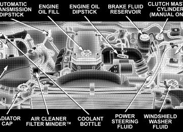
TO OPEN AND CLOSE THE HOOD
UNDERSTANDING THE FEATURES OF YOUR VEHICLE 113
To prevent possible damage, do not slam the hood to close it. Use a firm downward push at the front center of the hood to ensure that both latches engage.
To open the hood, two latches must be released. First pull the hood release lever located below the steering wheel at the base of the instrument panel. Once the hood is released you must reach into the opening beneath the center of the grille and push up the latch to release the safety catch before raising the hood.
114 UNDERSTANDING THE FEATURES OF YOUR VEHICLE
WARNING!
Interior Lights
If the hood is not fully latched, it could fly up when the vehicle is moving and block your forward vision. Be sure all hood latches are latched fully before driving.
LIGHTS
Courtesy/ dome lights are turned on when the front doors are opened, when the dimmer control (rotating wheel on the right side of the switch) is rotated to the second upward detent position, or if equipped, when the UNLOCK button is pressed on the key fob. Rotating the dimmer control to the optional fully upward position will
turn on the cargo light located on the back of the cab. When a door is open and the interior lights are on, rotating the dimmer control all the way down to the OFF detent will cause all the interior lights to go out. This is also known as the ⬙Party⬙ mode because it allows the doors to stay open for extended periods of time without discharging the vehicle’s battery. The brightness of the instrument panel lighting can be regulated by rotating the dimmer control up (brighter) or down (dimmer). When the headlights are ON you can supplement the brightness of the odometer, trip odom- eter, radio and overhead console by rotating the control up until you hear a click. This feature is termed the “Parade” mode and is useful when headlights are re- quired during the day.
UNDERSTANDING THE FEATURES OF YOUR VEHICLE 115
Battery Saver To protect the life of your vehicle’s battery, Load Shed- ding is provided for both the interior and exterior lights. If the ignition is off and any door is left ajar for 15
minutes or the dimmer control is rotated upwards for 15
minutes, the interior lights will automatically turn off. If the headlamps remain on while the ignition is cycled off, the exterior lights will automatically turn off after 5
minutes. After 5 minutes timeout, if the headlamp switch is turned off and then turned on, the exterior lights will automatically turn off after 15 minutes. If the dimmer control is rotated to the cargo lamp position with the ignition off, the cargo lamps will automatically turn off after 15 minutes. NOTE: Battery Saver mode is cancelled if the ignition is ON.116 UNDERSTANDING THE FEATURES OF YOUR VEHICLE
Headlamp Delay — If Equipped To aid in your exit, your vehicle, if equipped, can be programmed by your dealer with a headlamp delay that will leave the headlamps on for 0, 30, 60, or 90 seconds. This delay is initiated when the ignition is turned OFF while the headlamp switch is on, and then the headlamp switch is cycled off. The headlamps will remain on for 60
seconds. Headlamp delay can be cancelled by either turning the headlamp switch ON then OFF or by turning the ignition ON. Headlights, Parking Lights, Panel LightsWhen the headlight switch is rotated to the first position, the parking lights, taillights, side marker lights, license plate light and instrument panel lights are all turned on. Rotating the headlight switch to the first position will also turn on the cab top clearance lights, flare lights, and tailgate lights if the vehicle is equipped with these lights. The headlights will turn ON when the switch is rotated to the second position. The
⬙LAMP OUT⬙ indicator will be illuminated in the instru- ment cluster if a defective bulb or wiring circuit is detected for the headlamp system.
Your vehicle is equipped with plastic headlight lenses that are lighter and less susceptible to stone breakage than glass headlights.
Plastic is not as scratch resistant as glass and therefore different lens cleaning procedures must be followed. To minimize the possibility of scratching the lenses and reducing light output, avoid wiping with a dry cloth. To remove road dirt, wash with a mild soap solution fol- lowed by rinsing. Do not use abrasive cleaning components, solvents, steel wool or other abrasive materials to clean the lenses. Daytime Running Lights (Canada and Fleet Vehicles Only) The headlights on your vehicle will illuminate when the engine is started. This provides a constant ⬙Lights ON⬙ condition until the ignition is turned OFF. The lights illuminate at less than normal intensity. If the parking brake is applied the Daytime Running Lights will turn off.
UNDERSTANDING THE FEATURES OF YOUR VEHICLE 117
Lights-on Reminder If the headlights, parking lights, courtesy lights or cargo lights are left on, after the ignition is turned off, a continuous chime will sound when the driver’s door is opened. Fog Lights — If Equipped The foglights are turned ON by placing the headlight rotary control in the parking light or headlight position and pulling out the headlight rotary control. The fog lights will operate only when the parking lights are ON or when the vehicle headlights are ON low beam. An indicator light located left of the switch will illuminate when the fog lights are on. The fog lights will turn off when the switch is pressed in, when the headlight switch is rotated to the OFF position or the high beam is selected.
illuminated and a chime will be heard. If an indicator fails to light when the lever is moved, it would suggest that the switch or indicator lamp is defective. You can signal a lane change by moving the lever partially up or down.
118 UNDERSTANDING THE FEATURES OF YOUR VEHICLE
CARGO LIGHT The cargo lights are turned on by rotating the dimmer control to the optional fully upward position. The cargo lights will also turn on for 30 seconds when a key fob Unlock is pressed, as part of the illuminated entry feature.
MULTIFUNCTION CONTROL LEVER The multifunction control lever is located on the left side of the steering column. Turn Signals Move the lever up or down to signal a right-hand or left-hand turn. The arrow on either side of the instrument cluster flashes to indicate the direction of the turn, and proper operation of the front and rear turn signal lights. If a defective bulb or wiring circuit is detected for the turn signal system, the arrow indicators will flash at a faster rate. Also, the ⬙LAMP OUT⬙ indicator in the instrument cluster will be
Passing Light You can signal another vehicle with your headlights by partially pulling the multifunction lever toward the steer- ing wheel. This will cause the high beam headlights to turn on until the lever is released. High Beam / Low Beam Select Switch Pull the multifunction control lever fully toward the steering wheel to switch the headlights from HIGH or LOW beam.
UNDERSTANDING THE FEATURES OF YOUR VEHICLE 119
120 UNDERSTANDING THE FEATURES OF YOUR VEHICLE
Windshield Wipers
Intermittent Wiper System
The wipers and washers are operated by a switch in the multifunction control lever. Turn the end of the handle to select the desired wiper speed.
The intermittent feature of this system was designed for use when weather conditions make a single wiping cycle, with a variable pause between cycles, desirable. For maximum delay between cycles, rotate the control knob into the upper end of the delay range.
The delay interval decreases as you rotate the knob until it enters the LO continual speed position. The delay can be regulated from a maximum of about 15 seconds between cycles, to a cycle every 2 seconds. The delay intervals will double in duration when the vehicle speed is 10 mph (16 km) or less.
WARNING!
Sudden loss of visibility through the windshield could lead to an accident. You might not see other vehicles or other obstacles. To avoid sudden icing of the windshield during freezing weather, warm the windshield with defroster before and during wind- shield washer use.
UNDERSTANDING THE FEATURES OF YOUR VEHICLE 121
Windshield Washers To use the washer, push in on the washer knob on the end of the multifunction control lever and hold while spray is desired. If the washer knob is depressed while in the delay range, the wiper will operate for several seconds after the washer knob is released. It will then resume the intermittent interval previously selected. If the washer knob is pushed, for a period greater than 1 second, while in the OFF position, the wiper will wipe approximately three wipes, after the wash knob is released. To prevent freeze-up of your windshield washer system in cold weather, select a solution or mixture that meets or exceeds the temperature range of your climate. This rating information can be found on most washer fluid containers.
122 UNDERSTANDING THE FEATURES OF YOUR VEHICLE
TILT STEERING COLUMN To tilt the column, push down on the lever below the turn signal control and move the wheel up or down, as desired. Release the lever to lock the column firmly in place.
WARNING!
Tilting the steering column while the vehicle is moving is dangerous. Without a stable steering col- umn, you could lose control of the vehicle and have an accident. Adjust the column only while the ve- hicle is stopped. Be sure it is locked before driving.
DRIVER ADJUSTABLE PEDALS — IF EQUIPPED
Adjustment
UNDERSTANDING THE FEATURES OF YOUR VEHICLE 123
1. Position the driver seat so that you are at least 10
inches (254 mm) away from the airbag located in the center of the steering wheel. 2. Fasten and adjust the seatbelts. 3. Move the adjustable pedal switch, located to the left of the steering column near the parking brake release, in the direction you desire to move the pedals. 4. The pedals cannot be adjusted when the vehicle is in R (Reverse) or when the Speed Control is SET.The power adjustable accelerator and brake pedals allow the driver to establish a comfortable position relative to the steering wheel and pedals.
124 UNDERSTANDING THE FEATURES OF YOUR VEHICLE
CAUTION!
Do not place any article under the adjustable pedals or impede its ability to move as it may cause damage to the pedal controls. Pedal travel may become limited if movement is stopped by an obstruction in the adjustable pedal’s path.
ELECTRONIC SPEED CONTROL — IF EQUIPPED When engaged, this device takes over accelerator opera- tion at speeds greater than 35 mph (56 km/h). The controls are mounted on the steering wheel.
To Activate Push the ON/OFF button to the ON position. An indi- cator light in the instrument cluster illuminates when the system is on.
To Set At A Desired Speed When the vehicle has reached the desired speed, press and release the SET button. Release the accelerator and the vehicle will operate at the selected speed. To Deactivate A soft tap on the brake pedal, normal braking, clutch pressure while slowing the vehicle, or pressing the CAN- CEL button will deactivate speed control without erasing the memory. Pushing the ON/OFF button to the OFF position or turning off the ignition erases the memory.
WARNING!
Leaving the Speed Control ON when not in use is dangerous. You could accidentally set the system to cause it to go faster than you want. You could lose control and have an accident. Always leave the system OFF when you aren’t using it.
UNDERSTANDING THE FEATURES OF YOUR VEHICLE 125
To Resume Speed To resume a previously set speed, push and release the RESUME button. Resume can be used at any speed above 30 mph (50 km/h). To Vary The Speed Setting When the speed control is on, speed can be increased by pressing and holding the ACCEL button. When the button is released, a new set speed will be established. Tapping the ACCEL button once will result in a 2 mph (3km/h) speed increase. Each time the button is tapped, speed increases so that tapping the button three times will increase speed by 6 mph (10 km/h), etc. Tapping the DECEL button once will result in a 1 mph (2
km/h) speed decrease. Each time the button is tapped, speed will decrease. For example, tapping the button 3
times will decrease the speed by 3 mph (5 km/h), etc.126 UNDERSTANDING THE FEATURES OF YOUR VEHICLE
To decrease speed while the speed control is on, press and hold the DECEL button. Release the button when the desired speed is reached, and the new speed will be set. To Accelerate For Passing Depress the accelerator as you would normally. When the pedal is released, the vehicle will return to the set speed. NOTE: When driving uphill, at elevations above 2,000
ft. (610 meters), or when the vehicle is heavily loaded (especially when towing) the vehicle may slow below the SET speed. If the vehicle speed drops below 35 mph (56
km/h), the speed control will automatically disengage. If this happens, you can push down on the accelerator pedal to maintain the desired speed. Vehicles equipped with a 6–speed manual transmission should be operated in 4th or 5th gear under the above conditions.Vehicles equipped with a 4–speed automatic transmis- sion may exhibit several 4-3 downshifts under the above conditions. To reduce the frequency of the downshifts and to improve vehicle performance, it is advisable to lock out overdrive by pressing the O/D OFF button located at the end of the gear shifter.
WARNING!
Speed Control can be dangerous where the system can’t maintain a constant speed. Your vehicle could go too fast for the conditions, and you could lose control. An accident could be the result. Don’t use Speed Control in heavy traffic or on roads that are winding, icy, snow-covered, or slippery.
OVERHEAD CONSOLE— IF EQUIPPED The two optional overhead consoles may consist of the following features:
• Courtesy/Reading Lights • Compass/Temperature Mini-Trip Computer • Universal Garage Door Opener — If Equipped
(CMTC) — If Equipped
UNDERSTANDING THE FEATURES OF YOUR VEHICLE 127
Courtesy/Reading Lights In the middle of the console are two courtesy/reading lights. Both lights illuminate as courtesy lights when a door is opened, when the dimmer control is rotated to the courtesy light position (fully upward position), or when the UNLOCK button is pressed on the Remote Keyless Entry transmitter, if so equipped. These lights are also operated individually as reading lights by pressing the recessed area of the corresponding lens. NOTE: The courtesy/reading lights will remain on until the switch is pressed a second time, so be sure they have been turned off before leaving the vehicle. If the interior lights are left on after the vehicle is turned off, they will extinguish after 15 minutes.
128 UNDERSTANDING THE FEATURES OF YOUR VEHICLE
OVERHEAD CONSOLE WITH COMPASS/ TEMPERATURE MINI-TRIP COMPUTER — IF EQUIPPED This optional overhead console consists of the following: • Courtesy Lights • Compass/Temperature Mini-Trip Computer (CMTC)
This overhead console allows you to choose between a compass/temperature display and one of four trip con- ditions being monitored. US/M Button
Use this button to change the display from U.S. to metric measurement units.
RESET Button
UNDERSTANDING THE FEATURES OF YOUR VEHICLE 129
Global Reset If the RESET button is pressed twice within 2 seconds while in any of the 3 resettable displays, the Global Reset will reset all 3 displays. Step Button
Use this button to reset the following displays to zero: Average Fuel Economy Trip Odometer Elapsed time
Use this button to choose or cycle through the four trip conditions.
130 UNDERSTANDING THE FEATURES OF YOUR VEHICLE
Average Fuel Economy (AVG ECO) Shows the average fuel economy since the last reset. This display mode becomes less sensitive to instantaneous changes in fuel consumption as the number of total vehicle miles since the last reset increases. It is suggested that this mode be reset periodically for general operation or when driving conditions change significantly (for example, at the end of a trip or when a trailer is connected or disconnected). Distance To Empty (DTE) Shows the estimated distance that can be travelled with the fuel remaining in the tank. The estimated distance is determined by a weighted average of the instantaneous and average fuel economy, according to the current fuel tank level.
When Distance To Empty = 0, the fuel gauge pointer will initially be on the red “E” marker. At this point (fuel gauge pointer on the red “E” marker) there is reserve fuel capacity, which corresponds to approximately 8% of tank volume. This reserve capacity was put in place to prevent the likelihood of customers running out of fuel when operating at maximum load conditions in areas where there aren’t many gas stations. NOTE: The Distance To Empty will remain equal to zero, until the vehicle runs out of fuel or is refueled. Ram fuel tank volumes are as follows: • 26 gallons - 1500 short box models • 34 gallons - 1500 Quad Cab (if equipped)/2500/3500
• 35 gallons - 1500/2500/3500 long box modelsshort box models
Trip Odometer (ODO) This display shows the distance traveled since the last reset. Elapsed Time (ET) This display shows the accumulated ignition ON time since the last reset.
UNDERSTANDING THE FEATURES OF YOUR VEHICLE 131
C/T Button
Use this button to select a readout of the outside tem- perature and one of eight compass headings that indicate the direction in which the vehicle is facing.
132 UNDERSTANDING THE FEATURES OF YOUR VEHICLE
WARNING!
Manual Compass Calibration
Even if the display still reads a few degrees above 32°F ( 0°C), the road surface may be icy, particularly in woods or on bridges. Drive carefully under such conditions to prevent an accident and possible per- sonal injury or property damage.
Automatic Compass Calibration This compass is self-calibrating which eliminates the need to manually set the compass. When the vehicle is new, the compass may appear erratic and the CAL symbol will be displayed. After completing up to three 360° turns, with the vehicle traveling less than 5 mph (8 km/h), in an area free from large metal or metallic objects, the CAL symbol will turn off and the compass will function normally.
NOTE: To ensure proper compass calibration, make sure the compass variance is properly set before manu- ally calibrating the compass. If the compass appears erratic and the CAL symbol does not appear, you must manually put the compass into the “Calibration” mode. Recalibrating The Compass Turn on the ignition and set the display to “Compass/ Temperature.” Press and hold the RESET button to change the display between VAR (compass variance) and CAL (compass calibration) modes. When the CAL sym- bol is displayed complete one 360° turn in an area free from large metal objects or power lines. The CAL symbol will turn off and the compass will function normally.
UNDERSTANDING THE FEATURES OF YOUR VEHICLE 133
Compass Variance is the difference between magnetic north and geographic north. In some areas of the country, the difference between magnetic and geographic north is great enough to cause the compass to give false readings. If this occurs, the compass variance must be set according to the Compass Variance Map.
134 UNDERSTANDING THE FEATURES OF YOUR VEHICLE
To set the variance: Turn the ignition ON and set the display to “Compass/Temperature.” Press the RESET button approximately five seconds. The last variance zone number will be displayed. Press the STEP button to select the new variance zone and press the RESET button to resume normal operation. Outside Temperature Because the ambient temperature sensor is located un- derhood, engine temperature can influence the displayed temperature, therefore, temperature readings are slowly updated when the vehicle speed is below 20 mph (30
km/h) or during stop and go driving.GARAGE DOOR OPENER — IF EQUIPPED The HomeLink威 Universal Transceiver replaces up to three remote controls (hand held transmitters) that oper- ate devices such as garage door openers, motorized gates, or home lighting. It triggers these devices at the push of a button. The Universal Transceiver operates off your vehicle’s battery and charging system; no batteries are needed.
UNDERSTANDING THE FEATURES OF YOUR VEHICLE 135
WARNING!
A moving garage door can cause injury to people and pets in the path of the door. People or pets could be seriously or fatally injured. Only use this transceiver with a garage door opener that has a “stop and reverse” feature as required by federal safety stan- dards. This includes most garage door opener mod- els manufactured after 1982. Do not use a garage door opener without these safety features it could cause injury or death. Call toll-free 1–800–355–3515
or, on the Internet at www.homelink.com for safety information or assistance.For additional information on HomeLink威, call 1–800– 355–3515, or on the internet at www.homelink.com.
136 UNDERSTANDING THE FEATURES OF YOUR VEHICLE
Programming HomeLink
NOTE: When programming a garage door opener, it is advised to park outside the garage. It is also recom- mended that a new battery be placed in the hand-held transmitter of the device being programmed to HomeLink for quicker training and accurate transmis- sion of the radio-frequency signal. 1. Press and hold the two outer HomeLink buttons, and release only when the indicator light begins to flash (after 20 seconds). Do not hold the buttons for longer than 30
seconds and do not repeat step one to program a second and/or third hand-held transmitter to the remaining two HomeLink buttons.WARNING!
Vehicle exhaust contains carbon monoxide, a danger- ous gas. Do not run the vehicle’s exhaust while training the transceiver. Exhaust gas can cause seri- ous injury or death.
WARNING!
Your motorized door or gate will open and close while you are training the Universal Transceiver. Do not train the transceiver if people or pets are in the path of the door or gate. A moving door or gate can cause serious injury or death to people and pets or damage to objects.
2. Position the end of your hand-held transmitter 1-3
inches (3-8 cm) away from the HomeLink buttons while keeping the indicator light in view. 3. Simultaneously press and hold both the HomeLink button that you want to train and the hand-held trans- mitter buttons. Do not release the buttons until step 4
has been completed.UNDERSTANDING THE FEATURES OF YOUR VEHICLE 137
NOTE: Some gate operators and garage door openers may require you to replace this Programming Step 3 with procedures noted in the ⬙Gate Operator/Canadian Pro- gramming⬙ section. 4. The HomeLink indicator light will flash slowly and then rapidly after HomeLink successfully receives the frequency signal from the hand-held transmitter. Release both buttons after the indicator light changes from the slow to the rapid flash. 5. Press and hold the just trained HomeLink button and observe the indicator light. If the indicator light stays on constantly, programming is complete and your device should activate when the HomeLink button is pressed and released. NOTE: To program the remaining two HomeLink but- tons, begin with ⬙Programming⬙ step two. Do not repeat step one.
138 UNDERSTANDING THE FEATURES OF YOUR VEHICLE
If the indicator light blinks rapidly for two seconds and then turns to a constant light, continue with ⴖProgram- mingⴖ steps 6-8 to complete the programming of a rolling code equipped device (most commonly a garage door opener). 6. At the garage door opener receiver (motor-head unit) in the garage, locate the ⬙learn⬙ or ⬙smart⬙ button. This can usually be found where the hanging antenna wire is attached to the motor-head unit. 7. Firmly press and release the ⬙learn⬙ or ⬙smart⬙ button. (The name and color of the button may vary by manu- facturer.) NOTE: There are 30 seconds in which to initiate step eight. 8. Return to the vehicle and firmly press, hold for two seconds and release the programmed HomeLink button. Repeat the ⴖpress/hold/releaseⴖ sequence a second time,
rolling code
and, depending on the brand of the garage door opener (or other rolling code equipped device), repeat this sequence a third time to complete the programming. HomeLink should now activate your equipped device. NOTE: To program the remaining two HomeLink but- tons, begin with ⬙Programming⬙ step two. Do not repeat step one. For questions or comments, please contact HomeLink at www.homelink.com or 1-800-355-3515. Canadian Programming/Gate Programming Canadian radio-frequency laws require transmitter sig- nals to ⬙time-out⬙ (or quit) after several seconds of transmission which may not be long enough for HomeLink to pick up the signal during programming. Similar to this Canadian law, some U.S. gate operators are designed to ⬙time-out⬙ in the same manner.
If you live in Canada or you are having difficulties programming a gate operator by using the ⬙Program- ming⬙ procedures (regardless of where you live), replace ⴖProgramming HomeLinkⴖ step 3 with the following: If programming a garage door opener or gate NOTE: operator, it is advised to unplug the device during the ⬙cycling⬙ process to prevent possible overheating. 3. Continue to press and hold the HomeLink button while you press and release every two seconds (⬙cycle⬙) your hand-held transmitter until the frequency signal has successfully been accepted by HomeLink. (The indicator light will flash slowly and then rapidly.) Proceed with ⬙Programming⬙ step four to complete. Using HomeLink To operate, simply press and release the programmed HomeLink button. Activation will now occur for the trained device (i.e. garage door opener, gate operator, security system, entry door lock, home/office lighting,
UNDERSTANDING THE FEATURES OF YOUR VEHICLE 139
etc.). For convenience, the hand-held transmitter of the device may also be used at any time. In the event that there are still programming difficulties or questions, contact HomeLink at: www.homelink.com or 1-800-355- 3515. Erasing HomeLink Buttons To erase programming from the three buttons (individual buttons cannot be erased but can be ⬙reprogrammed⬙ - note below), follow the step noted: • Press and hold the two outer HomeLink buttons until the indicator light begins to flash-after 20 seconds. Release both buttons. Do not hold for longer that 30
seconds. HomeLink is now in the train (or learning) mode and can be programmed at any time beginning with ⬙Programming⬙ - step 2.140 UNDERSTANDING THE FEATURES OF YOUR VEHICLE
Reprogramming a Single HomeLink Button To program a device to HomeLink using a HomeLink button previously trained, follow these steps: 1. Press and hold the desired HomeLink button. DO NOT release the button. 2. The indicator light will begin to flash after 20 seconds. Without releasing the HomeLink button, proceed with ⬙Programming⬙ step 2
For questions or comments, contact HomeLink at: www.homelink.com or 1-800-355-3515. Security If you sell your vehicle, be sure to erase the frequencies. To erase all of the previously trained frequencies, hold down both outside buttons until the green light begins to flash. This device complies with part 15 of FCC rules and with RSS-210 of Industry Canada. Operation is subject to the following conditions:• This device may not cause harmful interference. • This device must accept any interference that may be received including interference that may cause undes- ired operation.
NOTE: Changes or modifications not expressly ap- proved by the party responsible for compliance could void the user’s authority to operate the equipment. HomeLink威 is a trademark owned by Johnson Controls, Inc.
POWER SUNROOF — IF EQUIPPED The power sunroof switch is located between the sun visors on the overhead console.
WARNING!
• Never leave children in a vehicle, with the keys in the ignition switch. Occupants, particularly unat- tended children, can become entrapped by the power sunroof while operating the power sunroof switch. Such entrapment may result in serious injury or death. • In an accident, there is a greater risk of being thrown from a vehicle with an open sunroof. You could also be seriously injured or killed. Always fasten your seat belt properly and make sure all passengers are properly secured too. • Do not allow small children to operate the sun- roof. Never allow fingers or other body parts, or any object to project through the sunroof opening. Injury may result.
UNDERSTANDING THE FEATURES OF YOUR VEHICLE 141
Opening Sunroof - Express Press the switch rearward and release, and the sunroof will open automatically from any position. The sunroof will open fully, then stop automatically. This is called Express Open. During Express Open operation, any movement of the sunroof switch will stop the sunroof. Closing Sunroof - Express Press the switch forward and release, and the sunroof will close automatically from any position. The sunroof will close fully and stop automatically. This is called Express Close. During Express Close operation, any movement of the switch will stop the sunroof. Pinch Protect Feature This feature will detect an obstruction in the opening of the sunroof during Express Close operation. If an ob- struction in the path of the sunroof is detected, the
142 UNDERSTANDING THE FEATURES OF YOUR VEHICLE
sunroof will automatically retract. Remove the obstruc- tion if this occurs. Next, press the switch forward and release to Express Close. Pinch Protect Override If a known obstruction (ice, debris, etc.) prevents closing, press the switch forward and hold for two seconds after the reversal occurs. This allows the sunroof to move towards the closed position. NOTE: Pinch protection is disabled while the switch is pressed. Venting Sunroof - Express Press and release the ⬙V⬙ button, and the sunroof will open to the vent position. This is called Express Vent, and will occur regardless of sunroof position. During Express Vent operation, any movement of the switch will stop the sunroof.
Sunshade Operation The sunshade can be opened manually. However, the sunshade will open automatically as the sunroof opens. NOTE: The sunshade cannot be closed if the sunroof is open. Wind Buffeting Wind buffeting can be described as the perception of pressure on the ears or a helicopter type sound in the ears. Your vehicle may exhibit wind buffeting with the windows down, or the sunroof (if equipped) in certain open or partially open positions. This is a normal occur- rence and can be minimized. If the buffeting occurs with the rear windows open, open the front and rear windows together to minimize the buffeting. If the buffeting occurs with the sunroof open, adjust the sunroof opening to minimize the buffeting or open any window.
UNDERSTANDING THE FEATURES OF YOUR VEHICLE 143
There is an additional Power Outlet in the center console of a 40/20/40 seat (if equipped). The outlet(s) has/have a fused direct feed from the battery so it/they receive power whether the ignition is ON or OFF. All accessories connected to this/these outlet(s) should be removed or turned OFF when the vehicle is not in use to protect the battery against discharge.
Sunroof Maintenance Use only a non-abrasive cleaner and a soft cloth to clean the glass panel. Ignition Off Operation The power sunroof switches remain active for 10 minutes after the ignition switch has been turned off. Opening either front door will cancel this feature. Sunroof Fully Closed Press the switch forward and release to ensure that the sunroof is fully closed.
ELECTRICAL POWER OUTLETS The auxiliary electrical outlet can provide power for in cab accessories designed for use with the standard “cigar lighter” plug. The outlet is located in the instrument panel below the ash receiver. A cap is attached to the outlet base indicating “Power Outlet” 12V-20A.
144 UNDERSTANDING THE FEATURES OF YOUR VEHICLE
CAUTION!
Electrical Outlet Use With Engine Off • Many accessories that can be plugged in draw power from the vehicle’s battery, even when not in use (i.e. cellular phones, etc.). Eventually, if plugged in long enough, the vehicle’s battery will discharge sufficiently to degrade battery life and/or prevent engine starting. • Accessories that draw higher power (i.e. coolers, vacuum cleaners, lights, etc.), will discharge the battery even more quickly. Only use these inter- mittently and with greater caution. • After the use of high power draw accessories, or long periods of the vehicle not being started (with accessories still plugged in), the vehicle must be driven a sufficient length of time to allow the generator to recharge the vehicle’s battery.
CIGAR LIGHTER AND ASH RECEIVER The ash receiver is opened and closed by pushing on the front surface of the receiver and then allowing the receiver to open. The cigar lighter is located above and to the left of the ash receiver. As a child safety precaution, the lighter only operates with the ignition switch ON. It heats when pushed in and pops out automatically when ready for use. To preserve the heating element, do not hold the lighter in the heating position.
UNDERSTANDING THE FEATURES OF YOUR VEHICLE 145
CUPHOLDERS
Front Instrument Panel Cupholders — Automatic Transmission Only Your new Ram truck is equipped with dual-opening adjustable cupholders. The cupholder is opened and closed by pushing on the front surface. Each opening in the cupholder is adjustable and will hold cups and mugs of various sizes.
146 UNDERSTANDING THE FEATURES OF YOUR VEHICLE
To secure the cup, place the cup to be held into one of the cup wells and then push the cupholder arm toward the cup until it is held stable.
Rear Cupholder — Quad Cab — If Equipped Quad Cab vehicles may be equipped with a rear cup- holder that consists of two cupwells for rear passenger convenience.
Cupholders with Automatic
STORAGE
Center Storage Compartment — If Equipped
The center portion of the seat folds down to provide an armrest with unique storage compartments under the lid. Push the button on the front of the armrest to raise the cover. Inside there is a power outlet (if equipped), removable coin holder (if equipped), and two dividers to
UNDERSTANDING THE FEATURES OF YOUR VEHICLE 147
configure the storage area into compartments. For ex- ample, compartments can be configured to hold a lap-top computer, a cellular telephone, CD’s and miscellaneous items. The top of the cover provides a generous firm surface to serve as a desktop for your “mobile office.”
WARNING!
• This armrest is not a seat. Anyone seated on the armrest could be seriously injured during vehicle operation, or an accident. Only use the center seating position when the armrest is fully upright. • In an accident, the latch may open if the total weight of the items stored exceeds about 10 lbs (4.5 kg). These items could be thrown about endangering occupants of Items stored should not exceed a total of 10 lbs (4.5 kg).
the vehicle.
148 UNDERSTANDING THE FEATURES OF YOUR VEHICLE
Storage and Seats — If Equipped Located in the center of the front 40/20/40 seat cushion there is a storage compartment. Standard cab models also have storage behind the seat. The Quad Cab models provide additional storage under the rear seat. Lift the seat to access the storage compartment.
FOLD FLAT LOAD FLOOR — IF EQUIPPED
Fold Flat Load Floor — If Equipped Quad Cab models with a 60/40 rear seat, may be equipped with a folding steel load floor.
WARNING!
Do not operate the vehicle with loose items stored on the load floor. While driving or in an accident you may experience, abrupt stopping, rapid acceleration, or sharp turns. Loose objects stored on the load floor may move around with force and strike occupants, resulting in serious or fatal injury.
UNDERSTANDING THE FEATURES OF YOUR VEHICLE 149
Unfolding the Load Floor 1. Lift the 60/40 seat cushion(s) to the upward position.
150 UNDERSTANDING THE FEATURES OF YOUR VEHICLE
2. Grasp the knob on the load floor and lift the knob until the load floor unfolds into position.
3. Reverse the procedure to store the load floor.
Positioning the Load Floor for Storage Access Under the Seat 1. Lift the 60/40 seat cushion(s) to the upward position. 2. Unsnap the securing snap located at either side of the load floor. 3. Lift the load floor up to access storage under the load floor.
WARNING!
Do not drive with the load floor in the up position. When stopping fast or in an accident, the load floor could move to the down position causing serious injury.
UNDERSTANDING THE FEATURES OF YOUR VEHICLE 151
PICKUP BOX
4. Reverse the procedure to put the load floor back in the secured down position before you operate the vehicle.
The pickup box on your new Ram has many features designed for utility and convenience. If you are installing a toolbox to the front of the NOTE: pickup box, you must use Mopar威 toolbox brackets available from your dealer.
152 UNDERSTANDING THE FEATURES OF YOUR VEHICLE
You can carry wide building materials (sheets of ply- wood, etc.) by building a raised load floor. Place lumber across the box in the indentations provided above the wheel housings and in the bulkhead dividers to form the floor.
WARNING!
The pickup box is intended for load carrying pur- poses only, not for passengers, who should sit in