- 2009 Dodge Challenger SRT8 Owners Manuals
- Dodge Challenger SRT8 Owners Manuals
- 2013 Dodge Challenger SRT8 Owners Manuals
- Dodge Challenger SRT8 Owners Manuals
- 2010 Dodge Challenger SRT8 Owners Manuals
- Dodge Challenger SRT8 Owners Manuals
- 2012 Dodge Challenger SRT8 Owners Manuals
- Dodge Challenger SRT8 Owners Manuals
- 2008 Dodge Challenger SRT8 Owners Manuals
- Dodge Challenger SRT8 Owners Manuals
- 2011 Dodge Challenger SRT8 Owners Manuals
- Dodge Challenger SRT8 Owners Manuals
- Download PDF Manual
-
to the heading “Programming A Rolling Code System.” Programming A Rolling Code System At the garage door opener motor (in the garage), locate the “learn” or “training” button.
This can usually be found where the hanging antenna wire is attached to the garage door opener motor (it is NOT the button normally used to open and close the door).
1 — Garage Door Opener 2 — Training Button
UNDERSTANDING THE FEATURES OF YOUR VEHICLE 145
1. Firmly press and release the LEARN or TRAINING button. The name and color of the button may vary by manufacturer. NOTE: You have 30 seconds in which to initiate the next step after the LEARN button has been pressed. 2. Return to the vehicle and press the programmed HomeLink威 button twice (holding the button for two seconds each time). If the device is plugged in and activates, programming is complete. If the device does not activate, press the button a third time (for two seconds) to complete the training. If you have any problems, or require assistance, please call toll-free 1–800–355–3515 or, on the Internet at www.HomeLink.com for information or assistance. To program the remaining two HomeLink威 buttons, repeat each step for each remaining button. DO NOT erase the channels.146 UNDERSTANDING THE FEATURES OF YOUR VEHICLE Gate Operator/Canadian Programming Canadian radio-frequency laws require transmitter sig- nals to “time-out” (or quit) after several seconds of transmission – which may not be long enough for HomeLink威 to pick up the signal during programming. Similar to this Canadian law, some U.S. gate operators are designed to “time-out” in the same manner. It may be helpful to unplug the device during the cycling process to prevent possible overheating of the garage door or gate motor. If you are having difficulties programming a garage door opener or a gate operator, replace “Programming HomeLink” Step 3 with the following: 3. Continue to press and hold the HomeLink威 button while you press and release - every two seconds (“cycle”) your handheld transmitter until HomeLink威
has successfully accepted the frequency signal. The EVIC display will change from “CHANNEL # TRAIN- ING” to “CHANNEL # TRAINED.” If you unplugged the device for training, plug it back in at this time. Then proceed with Step 4 under “Programming HomeLink威” earlier in this section. Using HomeLink姞 To operate, press the programmed HomeLink威 button. Activation will now occur for the trained device (i.e., garage door opener, gate operator, security system, entry door lock, home/office lighting, etc.,) The handheld transmitter of the device may also be used at any time.
and release
Reprogramming A Single HomeLink姞 Button To reprogram a channel that has been previously trained, follow these steps: 1. Place the ignition in the RUN position. 2. Press and hold the desired HomeLink威 button for 20 seconds until the EVIC display states “CHANNEL # TRAINING.” Do not release the button. 3. Without releasing the button, proceed with Program- ming HomeLink威 Step 2 and follow all remaining steps. Security It is advised to erase all channels before you sell or turn in your vehicle. To do this, press and hold the two outside buttons for 20 seconds until the EVIC message states “CHANNELS CLEARED.” Note that all channels will be erased. Indi- vidual channels cannot be erased.
UNDERSTANDING THE FEATURES OF YOUR VEHICLE 147
The HomeLink威 Universal Transceiver is disabled when the Vehicle Security Alarm is active. Troubleshooting Tips If you are having trouble programming HomeLink威, here are some of the most common solutions: • Replace the battery in the original transmitter. • Press the LEARN button on the garage door opener to • Did you unplug the device for training, and remembercomplete the training for rolling code.
to plug it back in?
If you are having any problems or require assistance, please call toll-free 1–800–355–3515 or, on the Internet at www.HomeLink.com for information or assistance.
148 UNDERSTANDING THE FEATURES OF YOUR VEHICLE General Information This device complies with FCC rules Part 15 and Industry Canada RSS-210. Operation is subject to the following two conditions: 1. This device may not cause harmful interference. 2. This device must accept any interference that may be received including interference that may cause undesired operation. NOTE: The transmitter has been tested and it complies with FCC and IC rules. Changes or modifications not expressly approved by the party responsible for compli- ance could void the user’s authority to operate the device. The term “IC:” before the certification/registration num- ber only signifies that Industry Canada technical specifi- cations were met.
POWER SUNROOF — IF EQUIPPED The power sunroof switch is located between the sun visors on the overhead console.
Power Sunroof Switch
WARNING!
• Never leave children in a vehicle with the key in the ignition switch (or with the ignition in the Accessory or Run position, for vehicles equipped with Keyless Go™). Occupants, particularly unat- tended children, can become entrapped by the power sunroof while operating the power sunroof switch. Such entrapment may result in serious injury or death. • In a collision, there is a greater risk of being thrown from a vehicle with an open sunroof. You could also be seriously injured or killed. Always fasten your seat belt properly and make sure all passengers are also properly secured.
UNDERSTANDING THE FEATURES OF YOUR VEHICLE 149
WARNING! (Continued)
• Do not allow small children to operate the sun- roof. Never allow your fingers, other body parts, or any object, to project through the sunroof opening. Injury may result.
Opening Sunroof — Partially Press and hold the switch in the rearward position. Release the switch when the sunroof is in the position desired and it will stop moving. If you continue to hold the switch in the rearward position, the sunroof will open fully and then stop automatically. Release the switch once the sunroof stops moving.
150 UNDERSTANDING THE FEATURES OF YOUR VEHICLE Opening Sunroof — Express Press the switch rearward and release, and the sunroof will open automatically from any position. The sunroof will open fully and then stop automatically. This is called “Express Open”. During Express Open operation, any movement of the sunroof switch will stop the sunroof. Closing Sunroof — Partially Press and hold the switch in the forward position. Release the switch when the sunroof is in the position desired and it will stop moving. If you continue to hold the switch in the forward position, the sunroof will close fully and then stop automatically. Release the switch once the sunroof stops moving. Closing Sunroof — Express Press the switch forward and release, and the sunroof will close automatically from any position. The sunroof will close fully and stop automatically. This is called
“Express Close”. During Express Close operation, any movement of the sunroof switch will stop the sunroof. Pinch Protect Feature This feature will detect an obstruction in the opening of the sunroof during Express Close operation. If an ob- struction in the path of the sunroof is detected, the sunroof will automatically retract. If this occurs remove the obstruction and press the switch forward and release to Express Close. Pinch Protect Override If a known obstruction (ice, debris, etc.) prevents closing, press the switch forward and hold for two seconds after the reversal occurs. This allows the sunroof to move towards the closed position. NOTE: Pinch protection is disabled while the switch is pressed.
Venting Sunroof — Express Press and release the Vent button in the center of the switch, and the sunroof will open to the vent position. This is called “Express Vent”, which operates regardless of sunroof position. During Express Vent operation, any movement of the sunroof switch will stop the sunroof. Sunshade Operation The sunshade can be opened manually. However, the sunshade will open automatically as the sunroof opens. NOTE: The sunshade cannot be closed if the sunroof is open. Wind Buffeting Wind buffeting can be described as the perception of pressure on the ears or a helicopter-type sound in the ears. Your vehicle may exhibit wind buffeting with the windows down, or the sunroof (if equipped) in certain open or partially open positions. This is a normal occur- rence and can be minimized. If the buffeting occurs with
UNDERSTANDING THE FEATURES OF YOUR VEHICLE 151
the sunroof open, then adjust the sunroof opening to minimize the buffeting or open any window. Sunroof Maintenance Use only a nonabrasive cleaner and a soft cloth to clean the glass panel. Ignition Off Operation The power sunroof switch will remain active for up to 60 minutes after the ignition is placed in the OFF posi- tion. Opening either door will cancel this feature. The time for this feature is programmable. Refer to “Elec- tronic Vehicle Information Center (EVIC)/Personal Set- tings (Customer-Programmable Features)” in “Under- standing Your Instrument Panel” for further information. Sunroof Fully Closed Press the switch forward and release to ensure that the sunroof is fully closed.152 UNDERSTANDING THE FEATURES OF YOUR VEHICLE ELECTRICAL POWER OUTLETS There are two 12 Volt (13 Amp) electrical power outlets on this vehicle. Both of the outlets are protected by a fuse. The front 12 Volt power outlet has power available only when the ignition is placed in the ACC or RUN position. This power outlet will also operate a conventional cigar lighter unit. If desired, the front power outlet can be converted by your authorized dealer to provide power when the ignition is placed in the OFF position. NOTE: • To ensure proper operation a MOPAR威 knob and • Do not exceed the maximum power of 160 Watts (13
Amps) at 12 Volts. If the 160 Watt (13 Amp) power rating is exceeded the fuse protecting the system will need to be replaced.element must be used.
Front Power Outlet
The center console power outlet is powered directly from the battery (power available at all times). Items plugged into this power outlet may discharge the battery and/or prevent the engine from starting.
WARNING!
To avoid serious injury or death: • Only devices designed for use in this type of outlet should be inserted into any 12 Volt outlet. • Do not touch with wet hands. • Close the lid when not in use and while driving • If this outlet is mishandled, it may cause an
the vehicle.
electric shock and failure.
UNDERSTANDING THE FEATURES OF YOUR VEHICLE 153
CAUTION!
• Many accessories that can be plugged in draw power from the vehicle’s battery even when not in use (i.e., cellular phones, etc.). Eventually, if plugged in long enough, the vehicle’s battery will discharge sufficiently to degrade battery life and/or prevent the engine from starting. • Accessories that draw higher power (i.e., coolers, vacuum cleaners, lights, etc.) will degrade the battery even more quickly. Only use these inter- mittently and with greater caution. • After the use of high power draw accessories or long periods of the vehicle not being started (with accessories still plugged in), the vehicle must be driven a sufficient length of time to allow the alternator to recharge the vehicle’s battery.
(Continued)
154 UNDERSTANDING THE FEATURES OF YOUR VEHICLE
CAUTION! (Continued)
• Power outlets are designed for accessory plugs only. Do not insert any other object in the power outlet as this will damage the outlet and blow the fuse. Improper use of the power outlet can cause damage not covered by your warranty.
CUPHOLDERS
Front Cupholders The front cupholders are located in the center console.
Front Cupholders
Illuminated Front Cupholders — If Equipped The front cupholders are illuminated with LEDs. They are turned on with the headlights or parking lights. Refer to “Lights” in “Understanding the Features of Your Vehicle” for further information.
Rear Cupholders The rear seat cupholders are located in the center armrest between the rear seats. The cupholders are positioned forward in the armrest and side-by-side to provide convenient access to beverage cans or bottles while maintaining a resting place for the rear occupants’ el- bows.
UNDERSTANDING THE FEATURES OF YOUR VEHICLE 155
Rear Cupholders
156 UNDERSTANDING THE FEATURES OF YOUR VEHICLE CONSOLE FEATURES
Sliding Center Console Armrest The center console armrest slides forward with three detents to provide flexibility for comfort, cupholder use and shifting ease.
Console Storage The center console has a storage compartment located underneath the armrest, and also contains a 12 Volt power outlet, a molded-in coin holder (designed to hold various size coins). The center console may also be equipped with a Universal Consumer Interface (UCI). UCI supports Mini, 4G, Photo, Nano, 5G iPod威 and iPhone威 devices. Refer to “Universal Consumer Interface (UCI) — If Equipped” in “Understanding Your Instru- ment Panel” for further information.
Sliding Console Armrest
UNDERSTANDING THE FEATURES OF YOUR VEHICLE 157
REAR WINDOW FEATURES
Rear Window Defroster
The rear window defroster button is located on the climate control (Mode) knob. Press this button to turn on the rear window defroster and the heated outside mirrors (if equipped). An indicator in the button will illuminate when the rear window defroster is on. The rear window defroster automatically turns off after ap- proximately 10 minutes. For an additional five minutes of operation, press the button a second time. NOTE: To prevent excessive battery drain, use the rear window defroster only when the engine is operating.
Center Console
158 UNDERSTANDING THE FEATURES OF YOUR VEHICLE
CAUTION!
Failure to follow these cautions can cause damage to the heating elements: • Use care when washing the inside of the rear window. Do not use abrasive window cleaners on the interior surface of the window. Use a soft cloth and a mild washing solution, wiping parallel to the heating elements. Labels can be peeled off after soaking with warm water. • Do not use scrapers, sharp instruments, or abra- sive window cleaners on the interior surface of the window. • Keep all objects a safe distance from the window.
UNDERSTANDING YOUR INSTRUMENT PANEL
CONTENTS
䡵 Instrument Panel Features 䡵 Instrument Cluster 䡵 Instrument Cluster Descriptions 䡵 Electronic Vehicle Information Center (EVIC)
. . . . . . . . . . . . . . . 162
. . . . . . . . . . . . . . . . . . . . 163
. . . . . . . . . . . 164
. . 175▫ Electronic Vehicle Information Center (EVIC)
Displays . . . . . . . . . . . . . . . . . . . . . . . . . . . 177
▫ Engine Oil Change Indicator System . . . . . . . 178
▫ Trip Functions . . . . . . . . . . . . . . . . . . . . . . 179
▫ Performance Features . . . . . . . . . . . . . . . . . 181▫ Keyless Enter-N-Go Display —
If Equipped . . . . . . . . . . . . . . . . . . . . . . . . 185
▫ Driver-Selectable Surround Sound (DSS) –
If Equipped . . . . . . . . . . . . . . . . . . . . . . . . 185
▫ Compass Display . . . . . . . . . . . . . . . . . . . . 186
▫ System Warnings (Customer InformationFeatures)
. . . . . . . . . . . . . . . . . . . . . . . . . . 188
▫ Personal Settings (Customer-Programmable
Features)
. . . . . . . . . . . . . . . . . . . . . . . . . . 188
160 UNDERSTANDING YOUR INSTRUMENT PANEL 䡵 Media Center 730N/430 (RER/RBZ) —
AM/FM Stereo Radio And CD/DVD/HDD/ NAV — If Equipped . . . . . . . . . . . . . . . . . . . . 192
▫ Operating Instructions — Voice CommandSystem (VR) — If Equipped . . . . . . . . . . . . . 192
▫ Operating Instructions — Uconnect™ Phone
— If Equipped . . . . . . . . . . . . . . . . . . . . . . 192
▫ Clock Setting Procedure — RBZ Radio . . . . . 192
▫ Clock Setting Procedure — RER Radio . . . . . 194
䡵 Media Center 130 (Sales Code RES) . . . . . . . . . 196
▫ Operating Instructions — Radio Mode . . . . . 196
▫ Operation Instructions — CD Mode For CDAnd MP3 Audio Play . . . . . . . . . . . . . . . . . 199
▫ Notes On Playing MP3 Files . . . . . . . . . . . . 202
▫ Operation Instructions - Auxiliary Mode . . . . 204䡵 Media Center 130 (RES/RSC) — AM/FM
Stereo Radio With CD Player (MP3 AUX Jack) And Sirius Radio . . . . . . . . . . . . . . . . . . . . . . 205
▫ Operating Instructions — Radio Mode . . . . . 205
▫ Operation Instructions — CD Mode For CDAnd MP3 Audio Play . . . . . . . . . . . . . . . . . 211
▫ Notes On Playing MP3 Files . . . . . . . . . . . . 213
▫ List Button (CD Mode For MP3 Play) . . . . . . 216
▫ Info Button (CD Mode For MP3 Play) . . . . . . 216䡵 Universal Consumer Interface (UCI) 0.5 —
If Equipped . . . . . . . . . . . . . . . . . . . . . . . . . . 217
▫ Connecting The iPod威 . . . . . . . . . . . . . . . . . 218
▫ Using This Feature . . . . . . . . . . . . . . . . . . . 219
▫ Controlling The iPod威 Using RadioButtons . . . . . . . . . . . . . . . . . . . . . . . . . . . 219
▫ Play Mode . . . . . . . . . . . . . . . . . . . . . . . . . 219
▫ List Or Browse Mode . . . . . . . . . . . . . . . . . 221䡵 Uconnect™ Multimedia (Satellite Radio) — If
Equipped (REN/REQ/RER/RES Radios Only) . . . . . . . . . . . . . . . . . . . . . . . . . 223
▫ System Activation . . . . . . . . . . . . . . . . . . . . 223
▫ Electronic Serial Number/SiriusIdentification Number (ESN/SID) . . . . . . . . . 223
▫ Selecting Uconnect™ Multimedia (Satellite)
Mode . . . . . . . . . . . . . . . . . . . . . . . . . . . . . 224
▫ Satellite Antenna . . . . . . . . . . . . . . . . . . . . . 224
▫ Reception Quality . . . . . . . . . . . . . . . . . . . . 224
▫ Operating Instructions - Uconnect™Multimedia (Satellite) Mode . . . . . . . . . . . . . 225
UNDERSTANDING YOUR INSTRUMENT PANEL 161
▫ Operating Instructions - Uconnect™ Phone
(If Equipped)
. . . . . . . . . . . . . . . . . . . . . . . 227
䡵 Kicker威 High Performance Sound System With
Driver-Selectable Surround (DSS) – If Equipped . . . . . . . . . . . . . . . . . . . . . . . . . . 227
䡵 Remote Sound System Controls —
If Equipped . . . . . . . . . . . . . . . . . . . . . . . . . . 228
䡵 CD/DVD Disc Maintenance . . . . . . . . . . . . . . 230
䡵 Radio Operation And Mobile Phones . . . . . . . 230
䡵 Climate Controls . . . . . . . . . . . . . . . . . . . . . . 231▫ Manual Air Conditioning And Heating
System . . . . . . . . . . . . . . . . . . . . . . . . . . . . 231
▫ Operating Tips . . . . . . . . . . . . . . . . . . . . . . 236162 UNDERSTANDING YOUR INSTRUMENT PANEL INSTRUMENT PANEL FEATURES
1 — Air Outlets 2 — Instrument Cluster 3 — Glove Compartment 4 — Radio
5 — Heated Seat Switch 6 — ESP OFF Switch 7 — Hazard Warning Switch 8 — Climate Control
9 — Ignition Switch 10 — Trunk Release Button 11 — Headlight Switch
INSTRUMENT CLUSTER
UNDERSTANDING YOUR INSTRUMENT PANEL 163
164 UNDERSTANDING YOUR INSTRUMENT PANEL INSTRUMENT CLUSTER DESCRIPTIONS
1. Fuel Gauge The pointer shows the level of fuel in the fuel tank when the ignition switch is in the ON/RUN position. 2. Trip Odometer Button Press this button to change the display from odometer to either of two trip odometer settings. The letter “A” or “B” will appear when in the trip odometer mode. Push in and hold the button for two seconds to reset the trip odometer to 0 miles (km). The odometer must be in TRIP mode to reset it. 3. Speedometer Indicates vehicle speed. 4. Electronic Speed Control Indicator Light
This light will turn on when the electronic speed control is on.
5. Tachometer The red segments indicate the maximum permissible engine revolutions per minute (RPM x 1000) for each gear range. Ease up on the accelerator before reaching the red area. 6. Charging System Warning Light
This light shows the status of the electrical charg- ing system. The light should turn on when the ignition switch is first placed in ON/RUN and remain on briefly as a bulb check. If the light stays on or turns on while driving, turn off some of the vehicle’s non-essential electrical devices (i.e., radio) or slightly increase engine speed (if at idle). If the light remains on, it means that the charging system is experiencing a problem. See your local authorized dealer to obtain service immediately. If jump starting is required, refer to “Jump Starting Procedures” in “What To Do In Emergencies”.
7. Electronic Throttle Control (ETC) Warning Light
This light will turn on briefly as a bulb check when the ignition switch is placed in ON/ RUN. This light will also turn on while the engine is running if there is a problem with the
Electronic Throttle Control (ETC) system. If the light comes on while the engine is running, safely bring the vehicle to a complete stop as soon as possible, place the shift lever in PARK, and cycle the ignition key. The light should turn off. If the light remains lit with the engine running, your vehicle will usually be drivable. However, see an authorized dealer for service as soon as possible.
UNDERSTANDING YOUR INSTRUMENT PANEL 165
If the light is flashing when the engine is running, immediate service is required. In this case, you may experience reduced performance, an elevated/rough idle or engine stall, and your vehicle may require towing. Also, have the system checked by an authorized dealer if the light does not come on during starting. 8. Temperature Gauge The temperature gauge shows engine coolant tempera- ture. Any reading within the normal range indicates that the engine cooling system is operating satisfactorily. The gauge pointer will likely indicate a higher tempera- ture when driving in hot weather, up mountain grades, or when towing a trailer. It should not be allowed to exceed the upper limits of the normal operating range.166 UNDERSTANDING YOUR INSTRUMENT PANEL
CAUTION!
WARNING!
Driving with a hot cooling system could damage your vehicle. If the temperature gauge reads 240°F (116°C) or greater, pull over and stop the vehicle. Idle the vehicle with the air conditioner turned off until the pointer drops back into the normal range 200– 230°F (93–110°C). If the pointer remains at 240°F (116°C) or greater and you hear a chime, turn the engine OFF immediately and call for service.
A hot engine cooling system is dangerous. You or others could be badly burned by steam or boiling coolant. You may want to call a service center if your vehicle overheats. If you decide to look under the hood yourself, refer to “Maintaining Your Vehicle” and follow the warnings under the Cooling System Pressure Cap paragraph.
9. Turn Signal Indicators
The arrow will flash with the exterior turn signal when the turn signal lever is operated.
NOTE: • A continuous chime will sound if the vehicle is driven more than 1 mile (1.6 km) with either turn signal on. • Check for an inoperative outside light bulb if either
indicator flashes at a rapid rate.
10. Airbag Warning Light
This light will turn on for four to eight seconds as a bulb check when the ignition switch is first turned to the ON/RUN position. If the light is either not on during starting, stays on, or turns on while driving, then have the system inspected at an authorized dealer as soon as possible. Refer to “Occupant Restraints” in “Things To Know Before Starting Your Vehicle” for further information. 11. Engine Temperature Warning Light
This light will turn on and a single chime will sound to warn of an overheated engine condition. When this light turns on, the engine temperature
UNDERSTANDING YOUR INSTRUMENT PANEL 167
is critically hot. The vehicle should be turned OFF immediately and serviced as soon as possible. 12. Electronic Stability Program (ESP)If this indicator light flashes during accelera- tion, ease up on the accelerator and apply as little throttle as possible. Adapt your speed and driving to the prevailing road conditions, and do not switch off the Electronic Stability Program (ESP). 13. Electronic Stability Program (ESP) Indicator Light / Brake Assist System (BAS) Warning Light
The malfunction light for the Electronic Stabil- ity Program (ESP) is combined with Brake Assist System (BAS). The yellow “ESP/BAS Warning Light” comes on when the ignition switch is placed in the ON/RUN position. They should go out with the engine running. If the “ESP/BAS Warn- ing Light” comes on continuously with the engine run- ning, a malfunction has been detected in either the ESP or
168 UNDERSTANDING YOUR INSTRUMENT PANEL the BAS system. If this light remains on after several ignition cycles, and the vehicle has been driven several miles (kilometers) at speeds greater than 30 mph (48 km/h), see an authorized dealer as soon as possible.
WARNING!
If the warning light remains on, the system may not be working and you will not have the benefit of ESP or BAS. You should adjust your speed and stopping distance to account for this lack of the feature or you could be in an accident and be seriously injured. You should take your vehicle to an authorized dealer.
14. Oil Pressure Warning Light
This light indicates low engine oil pressure. The light should turn on momentarily when the engine is started. If the light turns on while driving, stop the vehicle and shut off the engine as soon as possible. A chime will sound for four minutes when this light turns on.
Do not operate the vehicle until the cause is corrected. This light does not indicate how much oil is in the engine. The engine oil level must be checked under the hood. 15. High Beam Indicator
This indicator will turn on when the high beam headlights are on. Push the multifunction lever away from the steering wheel to switch the headlights to high beam. 16. Seat Belt Reminder Light
This light will turn on for four to eight seconds as a bulb check when the ignition switch is first placed in ON/RUN. A chime will sound if the driver’s seat belt is unbuckled during the bulb check. The Seat Belt Reminder Light will flash or remain on continu- ously if the driver’s seat belt remains unbuckled after the bulb check or when driving. Refer to “Occupant Re- straints” in “Things To Know Before Starting Your Ve- hicle” for further information.
17. Shift Lever Indicator — Automatic Transmission Only The Shift Lever Indicator is self-contained within the instrument cluster. It displays the gear position of the automatic transmission. 18. Front Fog Light Indicator — If Equipped
This indicator will illuminate when the front fog lights are on.
19. Odometer / Electronic Vehicle Information Center (EVIC) Display The odometer shows the total distance the vehicle has been driven. The trip odometer shows individual trip mileage. Refer to “Trip Odometer Button” for additional information. NOTE: U.S. Federal regulations require that upon trans- fer of vehicle ownership, the seller certify to the pur- chaser the correct mileage that the vehicle has been driven. If your odometer needs to be repaired or serviced,
UNDERSTANDING YOUR INSTRUMENT PANEL 169
the repair technician should leave the odometer reading the same as it was before the repair or service. If s/he cannot do so, then the odometer must be set at zero, and a sticker must be placed in the door jamb stating what the mileage was before the repair or service. It is a good idea for you to make a record of the odometer reading before the repair/service, so that you can be sure that it is properly reset, or that the door jamb sticker is accurate if the odometer must be reset at zero. This display shows the Electronic Vehicle Information Center (EVIC) messages when the appropriate conditions exist. For further information refer to Electronic Vehicle Information Center (EVIC). Loose Fuel Filler Cap Message If the vehicle diagnostic system determines that the fuel filler cap is loose, improperly installed, or damaged, a “Check Gascap” message will display in the odometer display area. Tighten the fuel filler cap properly and170 UNDERSTANDING YOUR INSTRUMENT PANEL press the TRIP ODOMETER button to turn off the message. If the problem continues, the message will appear the next time the vehicle is started. A loose, improperly installed, or damaged fuel filler cap may also turn on the Malfunction Indicator Light (MIL). 20. Brake Warning Light
This light monitors various brake functions, including brake fluid level and parking brake application. If the brake light turns on, it may indicate that the parking brake is applied, that the brake fluid level is low, or that there is a problem with the anti-lock brake system reservoir. If the light remains on when the parking brake has been disengaged, and the fluid level is at the full mark on the master cylinder reservoir, it indicates a possible brake hydraulic system malfunction. In this case, the light will remain on until the condition has been corrected.
The dual brake system provides a reserve braking capac- ity in the event of a failure to a portion of the hydraulic system. A leak in either half of the dual brake system is indicated by the Brake Warning Light which will turn on when the brake fluid level in the master cylinder has dropped below a specified level. The light will remain on until the cause is corrected. NOTE: The light may flash momentarily during sharp cornering maneuvers which change fluid level condi- tions. The vehicle should have service performed, and the brake fluid level checked. If brake failure is indicated, immediate repair is neces- sary.
WARNING!
Driving a vehicle with the brake light on is danger- ous. Part of the brake system may have failed. It will take longer to stop the vehicle. You could have a collision. Have the vehicle checked immediately.
Vehicles equipped with the Anti-Lock Brake System (ABS), are also equipped with Electronic Brake Force Distribution (EBD). In the event of an EBD failure, the Brake Warning Light will turn on along with the ABS Light. Immediate repair to the ABS system is required. Operation of the Brake Warning Light can be checked by turning the ignition switch from the OFF position to the ON/RUN position. The light should illuminate for ap- proximately two seconds. The light should then turn off unless the parking brake is applied or a brake fault is detected. If the light does not illuminate, have the light inspected by an authorized dealer.
UNDERSTANDING YOUR INSTRUMENT PANEL 171
The light also will turn on when the parking brake is applied with the ignition switch in the ON/RUN posi- tion. NOTE: This light shows only that the parking brake is applied. It does not show the degree of brake application. 21. Vehicle Security Light — If EquippedThis light will flash at a fast rate for approxi- mately 15 seconds, when the vehicle security alarm is arming, and then will flash slowly until the vehicle is disarmed.
22. Tire Pressure Monitoring Telltale Light
Each tire, including the spare (if provided), should be checked monthly, when cold and inflated to the inflation pressure recommended by the vehicle manufacturer on the vehicle placard or tire inflation pressure label. (If your vehicle has tires of a different size than the size indicated on the
172 UNDERSTANDING YOUR INSTRUMENT PANEL vehicle placard or tire inflation pressure label, you should determine the proper tire inflation pressure for those tires.) As an added safety feature, your vehicle has been equipped with a Tire Pressure Monitoring System (TPMS) that illuminates a low tire pressure telltale when one or more of your tires is significantly under-inflated. Accordingly, when the low tire pressure telltale illumi- nates, you should stop and check your tires as soon as possible, and inflate them to the proper pressure. Driving on a significantly under-inflated tire causes the tire to overheat and can lead to tire failure. Under-inflation also reduces fuel efficiency and tire tread life, and may affect the vehicle’s handling and stopping ability. Please note that the TPMS is not a substitute for proper tire maintenance, and it is the driver’s responsibility to
maintain correct tire pressure, even if under-inflation has not reached the level to trigger illumination of the TPMS low tire pressure telltale. Your vehicle has also been equipped with a TPMS malfunction indicator to indicate when the system is not operating properly. The TPMS malfunction indicator is combined with the low tire pressure telltale. When the system detects a malfunction, the telltale will flash for approximately one minute and then remain continuously illuminated. This sequence will continue upon subse- quent vehicle start-ups as long as the malfunction exists. When the malfunction indicator is illuminated, the sys- tem may not be able to detect or signal low tire pressure as intended. TPMS malfunctions may occur for a variety of reasons, including the installation of replacement or alternate tires or wheels on the vehicle that prevent the TPMS from functioning properly. Always check the TPMS malfunction telltale after replacing one or more
tires or wheels on your vehicle, to ensure that the replacement or alternate tires and wheels allow the TPMS to continue to function properly.
CAUTION!
The TPMS has been optimized for the original equipment tires and wheels. TPMS pressures and warning have been established for the tire size equipped on your vehicle. Undesirable system opera- tion or sensor damage may result when using re- placement equipment that is not of the same size, type, and/or style. Aftermarket wheels can cause sensor damage. Do not use tire sealant from a can, or balance beads if your vehicle is equipped with a TPMS, as damage to the sensors may result.
UNDERSTANDING YOUR INSTRUMENT PANEL 173
23. Anti-Lock Brake (ABS) Light
This light monitors the Anti-Lock Brake System (ABS). The light will turn on when the ignition switch is placed in the ON/RUN position and may stay on for as long as four seconds.
If the ABS light remains on or turns on while driving, it indicates that the Anti-Lock portion of the brake system is not functioning and that service is required. However, the conventional brake system will continue to operate normally if the BRAKE warning light is not on. If the ABS light is on, the brake system should be serviced as soon as possible to restore the benefits of Anti-Lock brakes. If the ABS light does not turn on when the ignition switch is placed in the ON/RUN position, have the light inspected by an authorized dealer.
174 UNDERSTANDING YOUR INSTRUMENT PANEL 24. Low Fuel Light
This light will turn on and a single chime will sound when the fuel level drops to 1/8 tank.
25. Malfunction Indicator Light (MIL)
The Malfunction Indicator Light (MIL) is part of an onboard diagnostic system called OBD. The OBD system monitors engine and automatic transmission control systems. The MIL will turn on when the ignition is in the ON/RUN position before engine start. If the MIL does not come on when turning the key from OFF to ON/RUN, have the condition checked promptly. Certain conditions such as a loose or missing gas cap, poor fuel quality, etc., may illuminate the MIL after engine start. The vehicle should be serviced if the MIL stays on through several of your typical driving cycles. In most situations, the vehicle will drive normally and will not require towing.
CAUTION!
Prolonged driving with the MIL on could cause damage to the engine control system. It also could affect fuel economy and drivability. If the MIL is flashing, severe catalytic converter damage and power loss will soon occur. Immediate service is required.
WARNING!
A malfunctioning catalytic converter, as referenced above, can reach higher temperatures than in normal operating conditions. This can cause a fire if you drive slowly or park over flammable substances such as dry plants or wood or cardboard, etc. This could result in death or serious injury to the driver, occu- pants or others.
ELECTRONIC VEHICLE INFORMATION CENTER (EVIC) The Electronic Vehicle Information Center (EVIC) fea- tures a driver-interactive display that is located in the instrument cluster.
Electronic Vehicle Information Center
UNDERSTANDING YOUR INSTRUMENT PANEL 175
This system conveniently allows the driver to select a variety of useful information by pressing the switches mounted on the steering wheel. The EVIC consists of the following: • System Status • Vehicle Information Warning Message Displays • Tire Pressure Monitor System • Personal Settings (Customer-Programmable Features) • Compass Display • Outside Temperature Display • Trip Computer Functions • Uconnect™ Phone Displays (If Equipped) • Uconnect™ gps Screens (If Equipped) • Audio Mode Display176 UNDERSTANDING YOUR INSTRUMENT PANEL
Selectable Surround [DSS])
• Surround Sound modes (if equipped with Driver- • Performance Features The system allows the driver to select information by pressing the following buttons mounted on the steering wheel. MENU Button
Press and release the MENU button and the mode displayed will change between Trip Functions, Performance Pages, Uconnect™ gps (If Equipped), System Warnings, System Sta-
tus, and Personal Settings. FUNCTION SELECT Button
Press the FUNCTION SELECT button to accept a selection. The FUNCTION SELECT button also functions as a remote sound system con- trol. Refer to “Remote Sound System Controls”.
SCROLL Button
Press the SCROLL button to scroll through Trip Functions, Performance Pages, Uconnect™ gps (If Equipped), System Status Messages, and Personal Settings (Customer-Programmable Features). The SCROLL button also functions as a remote sound system control. Refer to “Remote Sound System Controls”. AUDIO MODE Button
Press the AUDIO MODE button to select the Compass/Temp/Audio screen. Along with compass reading and outside temperature, this screen will display radio and media mode information depending on which radio is in the vehicle. Refer to “Remote Sound System Controls”.
Electronic Vehicle Information Center (EVIC) Displays When the appropriate conditions exist, the EVIC displays the following messages: • Turn Signal On (with a continuous warning chime if the vehicle is driven more than 1 mile [1.6 km] with either turn signal on) • Left Front Turn Signal Light Out (with a single chime) • Left Rear Turn Signal Light Out (with a single chime) • Right Front Turn Signal Light Out (with a single • Right Rear Turn Signal Light Out (with a single chime) • Personal Settings Not Available – Vehicle Not in PARK • Left/Right Door Ajar
chime)
motion)
UNDERSTANDING YOUR INSTRUMENT PANEL 177
• Door(s) Ajar (with a single chime if vehicle is in • Trunk Ajar (with a single chime) • Oil Change Required • Low Washer Fluid (with a single chime) • Channel # Transmit • Channel # Training • Channel # Trained • Clearing Channels • Channels Cleared • Did Not Train • Left Front Low Pressure (with a single chime) • Left Rear Low Pressure (with a single chime)
178 UNDERSTANDING YOUR INSTRUMENT PANEL
• Right Front Low Pressure (with a single chime) • Right Rear Low Pressure (with a single chime) • Check TPM System (with a single chime) • ESP Off • Check Gascap • Key Fob Battery Low • Service Keyless System • Wrong Key • Push Button or Insert Key/Turn To Run (refer to “Remote Starting System” in “Things To Know Before Starting Your Vehicle”)
• 1–4 SKIPSHIFT • 0-60 mph (0-100 km/h) • Braking Distance
• 1/8 Mile • 1/4 Mile • Instantaneous G-Force • Peak G-Force • Digital Speedometer Engine Oil Change Indicator System
Oil Change Required Your vehicle is equipped with an engine oil change indicator system. The “Oil Change Required” message will flash in the EVIC display for approximately 10 sec- onds after a single chime has sounded, to indicate the next scheduled oil change interval. The engine oil change indicator system is duty cycle based, which means the engine oil change interval may fluctuate, dependent upon your personal driving style.
Unless reset, this message will continue to display each time you turn the ignition switch to the ON/RUN position. To turn off the message temporarily, press and release the MENU button. To reset the oil change indica- tor system (after performing the scheduled maintenance) refer to the following procedure. 1. Turn the ignition switch to the ON position (Do not start the engine). 2. Fully depress the accelerator pedal, slowly, three times within 10 seconds. 3. Turn the ignition switch to the OFF/LOCK position. If the indicator message illuminates when you NOTE: start the vehicle, the oil change indicator system did not reset. If necessary, repeat this procedure. Trip Functions Press and release the MENU button until one of the following Trip Functions displays in the EVIC:
UNDERSTANDING YOUR INSTRUMENT PANEL 179
• Average Fuel Economy • Distance To Empty • Trip A • Trip B • Elapsed Time • Display Units of Measure in Press the SCROLL button to cycle through all the Trip Computer functions. The Trip Functions mode displays the following. Average Fuel Economy Shows the average fuel economy since the last reset. When the fuel economy is reset, the display will read “RESET” or show dashes for two seconds. Then, the
180 UNDERSTANDING YOUR INSTRUMENT PANEL history information will be erased, and the averaging will continue from the last fuel average reading before the reset. Distance To Empty (DTE) Shows the estimated distance that can be traveled with the fuel remaining in the tank. This estimated distance is determined by a weighted average of the instantaneous and average fuel economy, according to the current fuel tank level. DTE cannot be reset through the FUNCTION SELECT button. NOTE: Significant changes in driving style or vehicle loading will greatly affect the actual drivable distance of the vehicle, regardless of the DTE displayed value. When the DTE value is less than 30 miles (48 km) estimated driving distance, the DTE display will change to a text display of ⬙LOW FUEL.⬙ This display will continue until the vehicle runs out of fuel. Adding a
significant amount of fuel to the vehicle will turn off the ⬙LOW FUEL⬙ text and a new DTE value will display. Trip A Shows the total distance traveled for Trip A since the last reset. Trip B Shows the total distance traveled for Trip B since the last reset. Elapsed Time Shows the total elapsed time of travel since the last reset when the ignition switch is in the ACC position. Elapsed time will increment when the ignition switch is in the ON or START position. Display Units of Measure in To make your selection, press and release the FUNC- TION SELECT button until “ENGLISH” or “METRIC” appears.
To Reset The Display Reset will only occur while a resettable function is being displayed. Press and release the FUNCTION SELECT button once to clear the resettable function being dis- played. To reset all resettable functions, press and release the FUNCTION SELECT button a second time within three seconds of resetting the currently-displayed func- tion (>Reset ALL will display during this three-second window).
UNDERSTANDING YOUR INSTRUMENT PANEL 181
Performance Features
WARNING!
Measurement of vehicle statistics with the Perfor- mance Features is intended for off-highway or off- road use only and should not be done on any public roadways. It is recommended that these features be used in a controlled environment and within the limits of the law. The capabilities of the vehicle as measured by the performance pages must never be exploited in a reckless or dangerous manner, which can jeopardize the user’s safety or the safety of others. Only a safe, attentive, and skillful driver can prevent accidents.
182 UNDERSTANDING YOUR INSTRUMENT PANEL The Performance Features include the following: • 0-60 mph (0-100 km/h) • Braking Distance • 1/8 Mile • 1/4 Mile • Instantaneous G-Force • Peak G-Force • Digital Speedometer To access, press and release the MENU button until Performance Features displays in the EVIC. Press the SCROLL button to cycle through the features. Press the FUNCTION SELECT button to select a feature. The following describes each feature and its operation:
(100 km/h) in less then 10 seconds.
0-60 mph (0-100 km/h) When selected, this screen displays the time it takes for the vehicle to go from 0 to 60 mph (0 to 100 km/h) within 10 seconds. • The feature will “ready” when the vehicle speed is at 0 mph (0 km/h). The word “READY” will flash when conditions are met for the event to begin. • Dashes will display if the vehicle fails to reach 60 mph • The time will continue to display until the FUNCTION • Pressing the FUNCTION SELECT button will clear the current run time and display the vehicle’s best 0-60 mph (0-100 km/h) time. • To clear the vehicle’s best 0-60 mph (0-100 km/h) time, press and hold the FUNCTION SELECT button for five seconds.
SELECT button is pressed.
brakes at speeds above 30 mph (48 km/h).
Braking Distance When selected, this screen displays the vehicle’s braking distance and the speed at which the brake pedal was depressed. • This feature will only function when applying the • Engaging the parking brake will disable this feature. • The word “READY” will flash when conditions are • The distance and speed measurements display while • The distance measurement will be aborted if the brake pedal is released before the vehicle comes to a com- plete stop.
met for the event to begin.
the event is taking place.
UNDERSTANDING YOUR INSTRUMENT PANEL 183
display until pressed.
• The distance and speed measurements will continue to the FUNCTION SELECT button is • Pressing the FUNCTION SELECT button will clear the current run and prepare the cluster to record a new run.
1/8 Mile, 1/4 Mile When selected, this screen displays the time it takes the vehicle to travel 1/8 mile (1/4 mile) within 30 seconds and the vehicle’s speed when it reaches 1/8 mile (1/ 4 mile). • The feature will “ready” when the vehicle is at 0 mph (0 km/h). The word “READY” will flash when condi- tions are met for the event to begin.
• Dashes will display if
the vehicle fails to reach
1/8 mile (1/4 mile) in less then 30 seconds.
184 UNDERSTANDING YOUR INSTRUMENT PANEL
FUNCTION SELECT button is pressed.
• The time and speed will continue to display until the • Pressing the FUNCTION SELECT button will clear the current run and display the vehicle’s best 1/8 mile (1/4 mile) run. • To clear the vehicle’s best 1/8 mile (1/4 mile) run, press and hold the FUNCTION SELECT button for five seconds.
Instantaneous G-Force When selected, this screen displays the current G-Force (lateral and longitudinal) along with a friction circle that displays the directions of the forces. Peak G-Force When selected, this screen displays all four G-Force values (two lateral and two longitudinal).
• When a force greater than zero is measured, the display will update the value as it climbs. As the G-Force falls, the peak forces will continue to display. • Pressing the FUNCTION SELECT button will clear the
peak force values.
Digital Speedometer When selected, this screen displays vehicle speed and records top speed. • Press and hold the FUNCTION SELECT button for three seconds to toggle between current speed and top speed. • To reset top speed, quickly press and release the FUNCTION SELECT button when top speed is displayed.
Keyless Enter-N-Go Display — If Equipped When the ENGINE START/STOP button is pressed to change ignition switch positions, the Keyless Enter-N-Go icon momentarily appears in the EVIC display showing the new ignition switch position.
Keyless Enter-N-Go Display
UNDERSTANDING YOUR INSTRUMENT PANEL 185
The round symbol in the middle rotates to point at the new ignition switch position. If desired, the ignition switch position graphic can be set to be constantly visible by pressing the EVIC MENU button until the display appears. Refer to “Keyless Enter-N-Go” in “Starting And Operat- ing” for more information. NOTE: Under certain conditions, the display may be superseded by another display of higher priority. But when the ignition switch position is changed, the display always re-appears. Driver-Selectable Surround Sound (DSS) – If Equipped Press and release the MENU button until “Surround Sound” displays in the EVIC. The EVIC provides infor- mation on the current surround mode. • Stereo186 UNDERSTANDING YOUR INSTRUMENT PANEL
• Video Surround • Audio Surround While in the Surround Sound menu, press the FUNC- TION SELECT button to change surround modes. The Video Surround Mode will only be available for video media sources (DVDs, Video CDs, or other video media supported by the radio). Compass Display
The compass readings indicate the direction the vehicle is facing. Press and release the HOME button to display one of eight compass readings and the outside temperature.
HOME Button
NOTE: The system will display the last known outside temperature when starting the vehicle and may need to be driven several minutes before the updated tempera- ture is displayed. Engine temperature can also affect the
displayed temperature, therefore temperature readings are not updated when the vehicle is not moving. Automatic Compass Calibration This compass is self-calibrating, which eliminates the need to set the compass manually. When the vehicle is new, the compass may appear erratic and the EVIC will display “CAL” until the compass is calibrated. You may also calibrate the compass by completing one or more 360
degree turns (in an area free from large metal or metallic objects) until the “CAL” message displayed in the EVIC turns off. The compass will now function normally. Manual Compass Calibration If the compass appears erratic and the “CAL” message does not appear in the EVIC display, you must put the compass into the Calibration Mode manually as follows: 1. Turn the ignition switch ON.2. Press and hold the HOME button for approximately two seconds. 3. Press the SCROLL button until “Calibrate Compass” displays in the EVIC. 4. Press and release the FUNCTION SELECT button to start the calibration. The message “CAL” will display in the EVIC. 5. Complete one or more 360 degree turns (in an area free from large metal or metallic objects) until the “CAL” message turns off. The compass will now function normally. Compass Variance Compass Variance is the difference between Magnetic North and Geographic North. To compensate for the differences, the variance should be set for the zone where the vehicle is driven, per the zone map. Once properly set, the compass will automatically compensate for the differ- ences and provide the most accurate compass heading.
UNDERSTANDING YOUR INSTRUMENT PANEL 187
NOTE: Keep magnetic materials away from the top of the instrument panel, such as iPod’s, Mobile Phones, Laptops and Radar Detectors. This is where the compass module is located, and it can cause interference with the compass sensor, and it may give false readings.Compass Variance Map
1. Turn the ignition switch ON.
188 UNDERSTANDING YOUR INSTRUMENT PANEL 2. Press and hold the HOME button for approximately two seconds. 3. Press the SCROLL button until “Compass Variance” message and the last variance zone number displays in the EVIC. 4. Press and release FUNCTION SELECT button until the proper variance zone is selected according to the map. 5. Press and release the HOME button to exit. System Warnings (Customer Information Features) Press and release the MENU button until “SYSTEM WARNINGS” displays in the EVIC. Then, press the SCROLL button to display anyone of the following choices. • Oil Temperature Shows the actual oil temperature.
• Oil Pressure Shows the actual oil pressure. • Tire Pressure Shows the actual tire pressure for each tire (EXCLUDING THE SPARE TIRE). Personal Settings (Customer-Programmable Features) Personal Settings allows the driver to set and recall features when the transmission is in PARK. Press and release the MENU button until Personal Set- tings displays in the EVIC. Use the SCROLL button to display one of the following choices. Language When in this display, you may select one of three languages for all display nomenclature, including the trip functions and the Uconnect™ gps (if equipped). Press the
FUNCTION SELECT button while in this display to select English, Espanol, or Francais. Then, as you con- tinue, the information will display in the selected lan- guage. NOTE: The EVIC will not change the Uconnect™ lan- guage selection. Refer to “Uconnect™ Phone” in “Under- standing The Features Of Your Vehicle” for further information. Lock Doors Automatically at 15 mph (24 km/h) When ON is selected, both doors will lock automatically when the vehicle reaches a speed of 15 mph (24 km/h). To make your selection, press and release the FUNC- TION SELECT button until “ON” or “OFF” appears. Unlock Doors Automatically on Exit When ON is selected, both doors will unlock when the vehicle is stopped and the transmission is in the PARK or NEUTRAL position and the driver’s door is opened. To
UNDERSTANDING YOUR INSTRUMENT PANEL 189
make your selection, press and release the FUNCTION SELECT button until “ON” or “OFF” appears. Remote Key Unlock When Driver Door 1st Press is selected, only the driver’s door will unlock on the first press of the Remote Keyless Entry (RKE) transmitter UNLOCK button. When Driver Door 1st Press is selected, you must press the RKE transmitter UNLOCK button twice to unlock the passen- ger door. When All Doors 1st Press is selected, both of the doors will unlock on the first press of the RKE transmitter UNLOCK button. To make your selection, press and release the FUNCTION SELECT button until “Driver Door 1st Press” or “All Doors 1st Press” appears. Sound Horn with Remote Key Lock When ON is selected, a short horn sound will occur when the RKE transmitter LOCK button is pressed. This feature may be selected with or without the flash lights on190 UNDERSTANDING YOUR INSTRUMENT PANEL lock/unlock feature. To make your selection, press and release the FUNCTION SELECT button until “ON” or “OFF” appears. Flash Lights with Remote Key Lock When ON is selected, the front and rear turn signals will flash when the doors are locked or unlocked with the RKE transmitter. This feature may be selected with or without the sound horn on lock feature selected. To make your selection, press and release the FUNCTION SE- LECT button until “ON” or “OFF” appears. Headlamps On with Wipers (Available with Auto Headlights Only) When ON is selected, and the headlight switch is in the AUTO (A) position, the headlights will turn on approxi- mately 10 seconds after the wipers are turned on. The headlights will also turn off when the wipers are turned
off if they were turned on by this feature. To make your selection, press and release the FUNCTION SELECT button until “ON” or “OFF” appears. NOTE: Turning the headlights on during the daytime causes the instrument panel lights to dim. To increase the brightness, refer to “Lights” in “Understanding The Features Of Your Vehicle”. Delay Turning Headlights Off When this feature is selected, the driver can choose to have the headlights remain on for 0, 30, 60, or 90 seconds when exiting the vehicle. To make your selection, press and release the FUNCTION SELECT button until “0,” “30,” “60,” or “90” appears. Hill Start Assist (HSA) — If Equipped When on is selected, the HSA system is active. Refer to “Electronic Brake Control System” in “Starting And
Operating” for system function and operating informa- tion. To make your selection, press and release the FUNCTION SELECT button until “ON” or “OFF” appears. Turn Headlights On with Remote Key Unlock When this feature is selected, the headlights will activate and remain on for up to 90 seconds when the doors are unlocked with the RKE transmitter. To make your selec- tion, press and release the FUNCTION SELECT button until “OFF,” “30 sec.,” “60 sec.,” or “90 sec.” appears. Delay Power Off to Accessories Until Exit When this feature is selected, the power window switches, radio, Uconnect™ Phone (if equipped), power sunroof (if equipped), and ignition-powered power out- lets will remain active for up to 60 minutes after the ignition switch is turned OFF. Opening a vehicle door will cancel this feature. To make your selection, press and
UNDERSTANDING YOUR INSTRUMENT PANEL 191
release the FUNCTION SELECT button until “Off,” “45 sec.,” “5 min.,” “10 min.,” “30 min.,” or “60 min.” appears. Turn-by-Turn Navigation — If Equipped When ON is selected, the Turn-by-Turn directions will appear in the display as the vehicle approaches a desig- nated turn within a programmed route. To make your selection, press and release the FUNCTION SELECT button until “ON” or “OFF” appears. Display Units of Measure In The EVIC, odometer, and Uconnect™ gps (if equipped) can be changed between English and Metric units of measure. To make your selection, press and release the FUNCTION SELECT button until “ENGLISH” or “MET- RIC” appears.192 UNDERSTANDING YOUR INSTRUMENT PANEL MEDIA CENTER 730N/430 (RER/RBZ) — AM/FM STEREO RADIO AND CD/DVD/HDD/NAV — IF EQUIPPED
NOTE: The sales code is located on the lower right side of the unit’s faceplate. The RER and RBZ radios contain a CD/DVD player, USB port, and a 30-gigabyte hard drive (HDD). Sirius Satellite Radio is optional. The 6.5 in (16.5 cm) touch screen allows for easy menu selection. The RER radio also contains a Global Positioning System (GPS)-based Navigation system. Refer to your Uconnect™ Multimedia RER or RBZ user’s manual for detailed operating instructions. Operating Instructions — Voice Command System (VR) — If Equipped Refer to “Voice Command” in the Uconnect™ User Manual located on the DVD for further details.
Operating Instructions — Uconnect™ Phone — If Equipped Refer to “Uconnect™ Phone” in the Uconnect™ User Manual located on the DVD for further details. Clock Setting Procedure — RBZ Radio
To Manually Set the Clock 1. Turn on the radio. 2. Touch the screen where the time is displayed, the clock setting menu will appear on the screen. 3. To move the hour forward, touch the screen where the word “Hour” with the arrow pointing upward is dis- played. To move the hour backward, touch the screen where the word “Hour” with the arrow pointing down- ward is displayed. 4. To move the minute forward, touch the screen where the word “Min” with the arrow pointing upward is
displayed. To move the minute backward, touch the screen where the word “Min” with the arrow pointing downward is displayed. 5. To save the new time setting, touch the screen where the word “Save” is displayed. Changing Daylight Savings Time When selected, this feature will display the time of day in daylight savings time. Proceed as follows to change the current setting: 1. Turn on the radio. 2. Touch the screen where the time is displayed. The clock setting menu will appear on the screen. 3. When this feature is on, a check mark will appear in the box next to the words “Daylight Savings.” Touch the screen where the words “Daylight Savings” are dis- played to change the current setting.
UNDERSTANDING YOUR INSTRUMENT PANEL 193
Show Time if Radio is Off When selected, this feature will display the time of day on the touch screen when the radio is turned off. Proceed as follows to change the current setting: 1. Turn on the radio. 2. Touch the screen where the time is displayed. The clock setting menu will appear on the screen. 3. When this feature is on, a check mark will appear in the box next to the words “Show Time if Radio is Off.” Touch the screen where the words “Show Time if Radio is Off” are displayed to change the current setting. Changing the Time Zone 1. Turn on the radio. 2. Touch the screen where the time is displayed. The clock setting menu will appear on the screen.
194 UNDERSTANDING YOUR INSTRUMENT PANEL 3. Touch the screen where the words “Set Time Zone” are displayed. The time zone selection menu will appear on the screen. 4. Select a time zone by touching the screen where your selection appears. If you do not see a time zone that you want to select, touch the screen where the word “Page” is displayed to view additional time zones in the menu. 5. Touch the screen where the word “Save” is displayed. Clock Setting Procedure — RER Radio
Uconnect™ gps — RER Only The GPS receiver used in this system is synchronized to the time data being transmitted by the GPS satellite. The satellite clock is Greenwich Mean Time (GMT). This is the worldwide standard for time. This makes the system’s clock very accurate once the appropriate time zone and daylight savings information is set.
To Manually Set the Clock — RER 1. Turn on the radio. 2. Touch the screen where the time is displayed. 3. Touch the screen where “User Clock” is displayed, the clock setting menu will appear on the screen. 4. To move the hour forward, touch the screen where the word “Hour” with the arrow pointing upward is dis- played. To move the hour backward, touch the screen where the word “Hour” with the arrow pointing down- ward is displayed. 5. To move the minute forward, touch the screen where the word “Min” with the arrow pointing upward is displayed. To move the minute backward, touch the screen where the word “Min” with the arrow pointing downward is displayed.
6. To save the new time setting, touch the screen where the word “Save” is displayed. Changing Daylight Savings Time When selected, this feature will display the time of day in daylight savings time. Proceed as follows to change the current setting: 1. Turn on the radio. 2. Touch the screen where “User Clock” is displayed, the clock setting menu will appear on the screen. 3. When this feature is on, a check mark will appear in the box next to the words “Daylight Savings.” Touch the screen where the words “Daylight Savings” are dis- played to change the current setting. Show Time if Radio is Off When selected, this feature will display the time of day on the touch screen when the radio is turned off. Proceed as follows to change the current setting:
UNDERSTANDING YOUR INSTRUMENT PANEL 195
1. Turn on the radio. 2. Touch the screen where the time is displayed. 3. Touch the screen where “User Clock” is displayed, the clock setting menu will appear on the screen. 4. When this feature is on, a check mark will appear in the box next to the words “Show Time if Radio is Off.” Touch the screen where the words “Show Time if Radio is Off” are displayed to change the current setting. Changing the Time Zone 1. Turn on the radio. 2. Touch the screen where the time is displayed. 3. Touch the screen where “User Clock” is displayed, the clock setting menu will appear on the screen.
196 UNDERSTANDING YOUR INSTRUMENT PANEL 4. Touch the screen where the words “Set Time Zone” are displayed. The time zone selection menu will appear on the screen. 5. Select a time zone by touching the screen where your selection appears. If you do not see a time zone that you want to select, touch the screen where the word “Page” is displayed to view additional time zones in the menu. 6. Touch the screen where the word “Save” is displayed.
MEDIA CENTER 130 (SALES CODE RES)
NOTE: The radio sales code is located on the lower right side of the radio faceplate.
Media Center 130 (RES)
Operating Instructions — Radio Mode
NOTE: The ignition switch must be in the ON or ACC position to operate the radio.
Power Switch/Volume Control (Rotary) Push the ON/VOLUME control knob to turn on the radio. Push the ON/VOLUME control knob a second time to turn off the radio. Electronic Volume Control The electronic volume control turns continuously (360
degrees) in either direction, without stopping. Turning the ON/VOLUME control knob to the right increases the volume, and to the left decreases it. When the audio system is turned on, the sound will be set at the same volume level as last played. SEEK Buttons Press and release the SEEK buttons to search for the next listenable station in AM/FM mode. Press the right switch to seek up and the left switch to seek down. The radio will remain tuned to the new station until you make another selection. Holding either button will bypass stations without stopping, until you release it.UNDERSTANDING YOUR INSTRUMENT PANEL 197
TIME Button Press the TIME button to alternate display of the time and radio frequency. Clock Setting Procedure 1. Press and hold the TIME button until the hours blink. 2. Adjust the hours by turning the right side TUNE/ SCROLL control knob. 3. After adjusting the hours, press the right side TUNE/ SCROLL control knob to set the minutes. The minutes will begin to blink. 4. Adjust the minutes using the right side TUNE/ SCROLL control knob. Press the TUNE/SCROLL control knob to save time change. 5. To exit, press any button/knob, or wait five seconds.
198 UNDERSTANDING YOUR INSTRUMENT PANEL RW/FF Pressing the RW (Rewind) or FF (Fast Forward) buttons causes the tuner to search for the next frequency in the direction of the arrows. This feature operates in either AM or FM frequencies. TUNE Control Turn the rotary TUNE/SCROLL control knob clockwise to increase or counterclockwise to decrease the frequency. Setting the Tone, Balance, and Fade Push the rotary TUNE/SCROLL control knob and BASS will display. Turn the TUNE/SCROLL control knob to the right or left to increase or decrease the bass tones. Push the rotary TUNE/SCROLL control knob a second time and MID will display. Turn the TUNE/SCROLL control knob to the right or left to increase or decrease the mid-range tones.
Push the rotary TUNE/SCROLL control knob a third time and TREBLE will display. Turn the TUNE/SCROLL control knob to the right or left to increase or decrease the treble tones. Push the rotary TUNE/SCROLL control knob a fourth time and BALANCE will display. Turn the TUNE/ SCROLL control knob to the right or left to adjust the sound level from the right or left side speakers. Push the rotary TUNE/SCROLL control knob a fifth time and FADE will display. Turn the TUNE/SCROLL control knob to the left or right to adjust the sound level between the front and rear speakers. Push the rotary TUNE/SCROLL control knob again to exit setting tone, balance, and fade. AM/FM Button Press the buttons to select either AM or FM mode.
SET/RND Button — To Set the Pushbutton Memory When you are receiving a station that you wish to commit to pushbutton memory, press the SET/RND button. The symbol SET 1 will now show in the display window. Select the button (1 to 6) you wish to lock onto this station and press and release that button. If a button is not selected within five seconds after pressing the SET/RND button, the station will continue to play but will not be stored into pushbutton memory. You may add a second station to each pushbutton by repeating the above procedure with this exception: Press the SET/RND button twice and SET 2 will show in the display window. Each button can be set for SET 1 and SET 2 in both AM and FM. This allows a total of 12 AM and 12 FM stations to be stored into pushbutton memory. The stations stored in SET 2 memory can be selected by pressing the pushbutton twice.
UNDERSTANDING YOUR INSTRUMENT PANEL 199
Every time a preset button is used, a corresponding button number will display. Buttons 1 - 6
These buttons tune the radio to the stations that you commit to pushbutton memory (12 AM and 12 FM stations). DISC Button Pressing the DISC button will allow you to switch from AM/FM modes to Disc modes. Operation Instructions — CD MODE For CD And MP3 Audio Play NOTE: • The ignition switch must be in the ON or ACC • This radio is capable of playing compact discs (CD), recordable compact discs (CD-R), rewritable compactposition to operate the radio.
200 UNDERSTANDING YOUR INSTRUMENT PANEL
discs (CD-RW), compact discs with MP3 tracks and multisession compact discs with CD and MP3 tracks.
Inserting Compact Disc(s) Gently insert one CD into the CD player with the CD label facing up. The CD will automatically be pulled into the CD player and the CD icon will illuminate on the radio display. If a CD does not go into the slot more than 1.0 in (2.5 cm), a disc may already be loaded and must be ejected before a new disc can be loaded. If you insert a disc with the ignition ON and the radio ON, the unit will switch from radio to CD mode and begin to play when you insert the disc. The display will show the track number, and index time in minutes and seconds. Play will begin at the start of track 1.
CAUTION!
away and jam the player mechanism.
• This CD player will accept 4-3/4 in (12 cm) discs only. The use of other sized discs may damage the CD player mechanism. • Do not use adhesive labels. These labels can peel • RES is a single CD player. Do not attempt to insert • Dual-media disc types (one side is a DVD, the other side is a CD) should not be used, and they can cause damage to the player.
a second CD if one is already loaded.
EJECT Button - Ejecting a CD
Press the EJECT button to eject the CD.
If you have ejected a disc and have not removed it within 10 seconds, it will be reloaded. If the CD is not removed, the radio will reinsert the CD but will not play it. A disc can be ejected with the radio and ignition OFF. NOTE: Ejecting with the ignition OFF is not allowed on convertible or soft-top models (if equipped). SEEK Button Press the right SEEK button for the next selection on the CD. Press the left SEEK button to return to the beginning of the current selection, or return to the beginning of the previous selection if the CD is within the first second of the current selection. Pressing and holding the SEEK button will allow faster scrolling through the tracks in CD and MP3 modes. TIME Button Press this button to change the display from a large CD playing time display to a small CD playing time display.
UNDERSTANDING YOUR INSTRUMENT PANEL 201
RW/FF Press and hold the FF (Fast Forward) button and the CD player will begin to fast forward until FF is released, or RW or another CD button is pressed. The RW (Reverse) button works in a similar manner. AM/FM Button Press the button to select either AM or FM mode. SET/RND Button (Random Play Button) Press this button while the CD is playing to activate Random Play. This feature plays the selections on the compact disc in random order to provide an interesting change of pace. Press the right SEEK button to move to the next ran- domly selected track. Press the RND button a second time to stop Random Play.
202 UNDERSTANDING YOUR INSTRUMENT PANEL Notes on Playing MP3 Files The radio can play MP3 files; however, acceptable MP3
file recording media and formats are limited. When writing MP3 files, pay attention to the following restric- tions. Supported Media (Disc Types) The MP3 file recording media supported by the radio are CDDA, CD-R, CD-RW, MP3, and CDDA+MP3. Supported Medium Formats (File Systems) The medium formats supported by the radio are ISO 9660
Level 1 and Level 2 and includes the Joliet extension. When reading discs recorded using formats other than ISO 9660 Level 1 and Level 2, the radio may fail to read files properly and may be unable to play the file nor- mally. UDF and Apple HFS formats are not supported. The radio uses the following limits for file systems: • Maximum number of folder levels: 8• Maximum number of files: 255
• Maximum number of folders. (The radio display of file names and folder names is limited. For large numbers of files and/or folders, the radio may be unable to display the file name and folder name, and will assign a number instead. With a maximum number of files, exceeding 20 folders will result in this display. With in this 200 files, exceeding 50 folders will result display.) • Maximum number of characters in file/folder names: • Level 1: 12 (including a separator ⬙.⬙ and a three- • Level 2: 31 (including a separator ⬙.⬙ and a three-character extension)
character extension)
Multisession disc formats are supported by the radio. Multisession discs may contain combinations of normal CD audio tracks and computer files (including MP3 files).
Discs created with an option such as ⬙keep disc open after writing⬙ are most likely multisession discs. The use of multisession for CD audio or MP3 playback may result in longer disc loading times. Supported MP3 File Formats The radio will recognize only files with the *.MP3 exten- sion as MP3 files. Non-MP3 files named with the *.MP3
extension may cause playback problems. The radio is designed to recognize the file as an invalid MP3 and will not play the file. When using the MP3 encoder to compress audio data to an MP3 file, the bit rate and sampling frequencies in the following table are supported. In addition, variable bit rates (VBR) are also supported. The majority of MP3 files use a 44.1 kHz sampling rate and a 192, 160, 128, 96 or VBR bit rate.UNDERSTANDING YOUR INSTRUMENT PANEL 203
MPEG
Specification
MPEG-1 Audio
Layer 3
MPEG-2 Audio
Layer 3
Sampling
48, 44.1, 32
Frequency (kHz) Bit Rate (kbps) 320, 256, 224, 192, 160, 128, 112, 96, 80, 64, 56, 48, 40, 32
160, 128, 144, 112, 96, 80, 64, 56, 48, 40, 32, 24,24, 22.05, 16
16, 8
ID3 Tag information for artist, song title, and album title are supported for version 1 ID3 tags. ID3 version 2 is not supported by the radios. Playlist files are not supported. MP3 Pro files are not supported.
204 UNDERSTANDING YOUR INSTRUMENT PANEL Playback of MP3 Files When a medium containing MP3 data is loaded, the radio checks all files on the medium. If the medium contains a lot of folders or files, the radio will take more time to start playing the MP3 files. Loading times for playback of MP3 files may be affected by the following: • Media - CD-RW media may take longer to load than • Medium formats - Multisession discs may take longer • Number of files and folders - Loading times will
to load than non-multisession discs
CD-R media
increase with more files and folders
To increase the speed of disc loading, it is recommended to use CD-R media and single-session discs. To create a single-session disc, enable the “Disc at Once” option before writing to the disc.
Operation Instructions - Auxiliary Mode The auxiliary (AUX) jack is an audio input jack, which allows the user to plug in a portable device, such as an MP3 player, or cassette player, and utilize the vehicle’s audio system to amplify the source and play through the vehicle speakers. Pressing the DISC/AUX button will change the mode to auxiliary device if the AUX jack is connected. NOTE: The AUX device must be turned on and the device’s volume set to proper level. If the AUX audio is not loud enough, turn the device’s volume up. If the AUX audio sounds distorted, turn the device’s volume down. TIME Button (Auxiliary Mode) Press this button to change the display to time of day. The time of day will display for five seconds (when ignition is OFF).
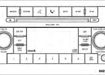
MEDIA CENTER 130 (RES/RSC) — AM/FM STEREO RADIO WITH CD PLAYER (MP3 AUX JACK) AND SIRIUS RADIO
NOTE: The radio sales code is located on the lower right side of the radio faceplate.
UNDERSTANDING YOUR INSTRUMENT PANEL 205
Operating Instructions — Radio Mode
NOTE: The ignition switch must be in the ON/RUN or ACC position to operate the radio. Power Switch/Volume Control (Rotary) Push the ON/VOLUME control knob to turn on the radio. Push the ON/VOLUME control knob a second time to turn off the radio. Electronic Volume Control The electronic volume control turns continuously (360
degrees) in either direction without stopping. Turning the ON/VOLUME control knob to the right increases the volume and to the left decreases it. When the audio system is turned on, the sound will be set at the same volume level as last played.Media Center 130 (RES/RSC)
206 UNDERSTANDING YOUR INSTRUMENT PANEL SEEK Buttons Press and release the SEEK buttons to search for the next listenable station in AM/FM mode. Press the right switch to seek up and the left switch to seek down. The radio will remain tuned to the new station until you make another selection. Holding either button will bypass stations without stopping until you release it. Voice Command System (Radio) — If Equipped Refer to “Voice Command” in the Uconnect™ User Manual located on the DVD for further details. Voice Command Button Uconnect™ Phone — If Equipped Press this button to operate the Uconnect™ Phone feature (if equipped). Refer to “Voice Command” in the Uconnect™ User Manual located on the DVD for further details.
If your vehicle is not equipped with or this feature is not available on your vehicle, a “Not Equipped With Uconnect” message will display on the radio screen. Phone Button Uconnect™ Phone — If Equipped Press this button to operate the Uconnect™ Phone feature (if equipped). Refer to “Uconnect™ Phone” in the Uconnect™ User Manual located on the DVD for further details. If your vehicle is not equipped with or this feature is not available on your vehicle, a “Not Equipped With Uconnect” message will display on the radio screen. TIME Button Press the TIME button to alternate display of the time and radio frequency.
Clock Setting Procedure 1. Press and hold the TIME button until the hours blink. 2. Adjust the hours by turning the right side TUNE/ SCROLL control knob. 3. After adjusting the hours, press the right side TUNE/ SCROLL control knob to set the minutes. The minutes will begin to blink. 4. Adjust the minutes using the right side TUNE/ SCROLL control knob. Press the TUNE/SCROLL control knob to save time change. 5. To exit, press any button/knob or wait five seconds. The clock can also be set by pressing the SETUP button. For vehicles equipped with satellite radio, press the SETUP button, use the TUNE/SCROLL control to select SET CLOCK, and then follow the above procedure,
UNDERSTANDING YOUR INSTRUMENT PANEL 207
starting at Step 2. For vehicles not equipped with satellite radio, press the SETUP button and then follow the above procedure, starting at Step 2. INFO Button Press the INFO button for an RDS station (one with call letters displayed). The radio will return a Radio Text message broadcast from an FM station (FM mode only). RW/FF Pressing the RW (Rewind) or FF (Fast Forward) buttons causes the tuner to search for the next frequency in the direction of the arrows. This feature operates in either AM or FM frequencies. TUNE Control Turn the rotary TUNE/SCROLL control knob clockwise to increase or counterclockwise to decrease the frequency.208 UNDERSTANDING YOUR INSTRUMENT PANEL Setting the Tone, Balance, and Fade Push the rotary TUNE/SCROLL control knob and BASS will display. Turn the TUNE/SCROLL control knob to the right or left to increase or decrease the bass tones. Push the rotary TUNE/SCROLL control knob a second time and MID will display. Turn the TUNE/SCROLL control knob to the right or left to increase or decrease the mid-range tones. Push the rotary TUNE/SCROLL control knob a third time and TREBLE will display. Turn the TUNE/SCROLL control knob to the right or left to increase or decrease the treble tones. Push the rotary TUNE/SCROLL control knob a fourth time and BALANCE will display. Turn the TUNE/ SCROLL control knob to the right or left to adjust the sound level from the right or left side speakers.
Push the rotary TUNE/SCROLL control knob a fifth time and FADE will display. Turn the TUNE/SCROLL control knob to the left or right to adjust the sound level between the front and rear speakers. Push the rotary TUNE/SCROLL control knob again to exit setting tone, balance, and fade. MUSIC TYPE Button Pressing this button once will turn on the Music Type mode for five seconds. Pressing the MUSIC TYPE button or turning the TUNE/SCROLL control knob within five seconds will allow the program format type to be se- lected. Many radio stations do not currently broadcast Music Type information.
Toggle the MUSIC TYPE button to select the following format types:
Program Type
No program type
or undefined Adult Hits Classical
Classic Rock
College Country
Foreign Language
Information
Jazz News
Nostalgia
Oldies
16-Digit
Character Display
None
Adlt Hit Classicl Cls Rock College Country Language
Inform Jazz News
Nostalga Oldies
UNDERSTANDING YOUR INSTRUMENT PANEL 209
Program Type
Personality
Public
Rhythm and Blues Religious Music Religious Talk
Rock Soft
Soft Rock
Soft Rhythm and Blues
Sports Talk Top 40
Weather16-Digit
Character Display
Persnlty Public R & B
Rel Musc Rel Talk
Rock Soft
Soft Rck Soft R&B
Sports Talk Top 40
Weather210 UNDERSTANDING YOUR INSTRUMENT PANEL By pressing the SEEK button when the Music Type icon is displayed, the radio will be tuned to the next frequency station with the same selected Music Type name. The Music Type function only operates when in the FM mode. If a preset button is activated while in the Music Type (Program Type) mode, the Music Type mode will be exited and the radio will tune to the preset station. SETUP Button Pressing the SETUP button allows you to select between the following items: • Set Clock — Pressing the SELECT button will allow you to set the clock. Adjust the hours by turning the TUNE/SCROLL control knob. After adjusting the hours, press the TUNE/SCROLL control knob to set the minutes. The minutes will begin to blink. Adjust
the minutes using the right side TUNE/SCROLL control knob. Press the TUNE/SCROLL control knob to save time change.
AM/FM Button Press the button to select either AM or FM mode. SET/RND Button — To Set the Pushbutton Memory When you are receiving a station that you wish to commit to pushbutton memory, press the SET/RND button. The symbol SET 1 will now show in the display window. Select the button (1–6) you wish to lock onto this station and press and release that button. If a button is not selected within five seconds after pressing the SET/ RND button, the station will continue to play but will not be stored into pushbutton memory.
You may add a second station to each pushbutton by repeating the above procedure with this exception: Press the SET/RND button twice and SET 2 will show in the display window. Each button can be set for SET 1 and SET 2 in both AM and FM. This allows a total of 12 AM and 12 FM stations to be stored into pushbutton memory. The stations stored in SET 2 memory can be selected by pressing the pushbutton twice. Every time a preset button is used, a corresponding button number will display. Buttons 1 - 6
These buttons tune the radio to the stations that you commit to pushbutton memory (12 AM and 12 FM stations). DISC/AUX Button Pressing the DISC/AUX button will allow you to switch from AM/FM modes to DISC/AUX mode.UNDERSTANDING YOUR INSTRUMENT PANEL 211
Operation Instructions — CD MODE for CD and MP3 Audio Play NOTE: • The ignition switch must be in the ON/RUN or ACC • This radio is capable of playing compact discs (CD), recordable compact discs (CD-R), rewritable compact discs (CD-RW), compact discs with MP3 tracks and multisession compact discs with CD and MP3 tracks.
position to operate the radio.
Inserting Compact Disc(s) Gently insert one CD into the CD player with the CD label facing up. The CD will automatically be pulled into the CD player and the CD icon will illuminate on the radio display. If a CD does not go into the slot more than 1.0 in (2.5 cm), a disc may already be loaded and must be ejected before a new disc can be loaded.
212 UNDERSTANDING YOUR INSTRUMENT PANEL If you insert a disc with the ignition ON/RUN and the radio ON, the unit will switch from radio to CD mode and begin to play when you insert the disc. The display will show the track number, and index time in minutes and seconds. Play will begin at the start of track 1.
CAUTION!
away and jam the player mechanism.
• This CD player will accept 4–3/4 in (12 cm) discs only. The use of other sized discs may damage the CD player mechanism. • Do not use adhesive labels. These labels can peel • RES is a single CD player. Do not attempt to insert • Dual-media disc types (one side is a DVD, the other side is a CD) should not be used, and they can cause damage to the player.
a second CD if one is already loaded.
EJECT Button - Ejecting a CD
Press the EJECT button to eject the CD.
If you have ejected a disc and have not removed it within 10 seconds, it will be reloaded. If the CD is not removed, the radio will reinsert the CD but will not play it. A disc can be ejected with the radio and ignition OFF. NOTE: Ejecting with the ignition OFF is not allowed on convertible or soft-top models (if equipped). SEEK Button Press the right SEEK button for the next selection on the CD. Press the left SEEK button to return to the beginning of the current selection, or return to the beginning of the previous selection if the CD is within the first second of
the current selection. Pressing and holding the SEEK button will allow faster scrolling through the tracks in CD and MP3 modes. TIME Button Press this button to change the display from a large CD playing time display to a small CD playing time display. RW/FF Press and hold FF (Fast Forward) and the CD player will begin to fast forward until FF is released or RW or another CD button is pressed. The RW (Reverse) button works in a similar manner. AM/FM Button Press the button to select either AM or FM mode.
UNDERSTANDING YOUR INSTRUMENT PANEL 213
SET/RND Button (Random Play Button) Press this button while the CD is playing to activate Random Play. This feature plays the selections on the compact disc in random order to provide an interesting change of pace. Press the right SEEK button to move to the next ran- domly selected track. Press the SET/RND button a second time to stop Ran- dom Play. Notes On Playing MP3 Files The radio can play MP3 files; however, acceptable MP3
file recording media and formats are limited. When writing MP3 files, pay attention to the following restric- tions. Supported Media (Disc Types) The MP3 file recording media supported by the radio are CDDA, CD-R, CD-RW, MP3, and CDDA+MP3.214 UNDERSTANDING YOUR INSTRUMENT PANEL Supported Medium Formats (File Systems) The medium formats supported by the radio are ISO 9660
Level 1 and Level 2 and includes the Joliet extension. When reading discs recorded using formats other than ISO 9660 Level 1 and Level 2, the radio may fail to read files properly and may be unable to play the file nor- mally. UDF and Apple HFS formats are not supported. The radio uses the following limits for file systems: • Maximum number of folder levels: 8
• Maximum number of files: 255
• Maximum number of folders. (The radio display of file names and folder names is limited. For large numbers of files and/or folders, the radio may be unable to display the file name and folder name and will assign a number instead. With a maximum number of files,exceeding 20 folders will result in this display. With in this 200 files, exceeding 50 folders will result display.)