- 2013 Chrysler TOWN and Country Owners Manuals
- Chrysler TOWN and Country Owners Manuals
- 2006 Chrysler TOWN and Country Owners Manuals
- Chrysler TOWN and Country Owners Manuals
- 2011 Chrysler TOWN and Country Owners Manuals
- Chrysler TOWN and Country Owners Manuals
- 2007 Chrysler TOWN and Country Owners Manuals
- Chrysler TOWN and Country Owners Manuals
- 2010 Chrysler TOWN and Country Owners Manuals
- Chrysler TOWN and Country Owners Manuals
- 2005 Chrysler TOWN and Country Owners Manuals
- Chrysler TOWN and Country Owners Manuals
- 2009 Chrysler TOWN and Country Owners Manuals
- Chrysler TOWN and Country Owners Manuals
- 2004 Chrysler TOWN and Country Owners Manuals
- Chrysler TOWN and Country Owners Manuals
- 2012 Chrysler TOWN and Country Owners Manuals
- Chrysler TOWN and Country Owners Manuals
- 2008 Chrysler TOWN and Country Owners Manuals
- Chrysler TOWN and Country Owners Manuals
- Download PDF Manual
-
The TPMS will continue to warn the driver of low tire pressure as long as the condition exists, and will not turn off until the tire pressure is at or above recommended cold tire placard pressure. Once the low tire pressure warning has been illuminated, the tire pressure must be
increased to the recommended cold tire placard pressure in order for the TPMS warning lamp to be turned off. The system will automatically update and the TPMS warning lamp will extinguish once the updated tire pressures have been received. The vehicle may need to be driven for up to 10 minutes above 15 mph (25 km/h) to receive this information. For example, your vehicle may have a recommended cold (parked for more than three hours) tire pressure of 35 psi (241 kPa). If the ambient temperature is 68°F (20°C) and the measured tire pressure is 30 psi (207 kPa), a temperature drop to 20°F (-7°C) will decrease the tire pressure to approximately 26 psi (179 kPa). This tire pressure is sufficiently low enough to turn on the TPMS Warning Light. Driving the vehicle may cause the tire pressure to rise to approximately 30 psi (207 kPa), but the TPMS Warning Light will still be on. In this situation, the
STARTING AND OPERATING 371
TPMS Warning Light will turn off only after the tires have been inflated to the vehicle’s recommended cold tire pressure value.
CAUTION!
The TPMS has been optimized for the original equipment tires and wheels. TPMS pressures have been established for the tire size equipped on your vehicle. Undesirable system operation or sensor damage may result when using replacement equip- ment that is not of the same size, type, and/or style. Aftermarket wheels can cause sensor damage. Do not use aftermarket sealants or balance beads if your vehicle is equipped with a TPMS, as damage to the sensors may result.
372 STARTING AND OPERATING
CAUTION!
After inspecting or adjusting the tire pressure always reinstall the valve stem cap. This will prevent mois- ture and dirt from entering the valve stem, which could damage the TPMS SENSOR.
NOTE: † The TPMS is not intended to replace normal tire care and maintenance, or to provide warning of a tire failure or condition. † The TPMS should not be used as a tire pressure gauge † Driving on a significantly under-inflated tire causes the tire to overheat and can lead to tire failure. Under-inflation also reduces fuel efficiency and tire tread life, and may affect the vehicle’s handling and stopping ability.
while adjusting your tire pressure.
† The TPMS is not a substitute for proper tire mainte- nance, and it is the driver’s responsibility to maintain correct tire pressure, using an accurate tire pressure gage, even if under-inflation has not reached the level to trigger illumination of the TPMS Warning Lamp.
NOTE: Seasonal temperature changes will affect tire pressure, and the TPMS will monitor the actual tire pressure in the tire. BASIC TPMS WITHOUT EVIC — IF EQUIPPED The TPMS uses wireless technology with wheel rim mounted electronic sensors to monitor tire pressure lev- els. Sensors, mounted to each wheel as part of the valve stem, transmit tire pressure readings to the Receiver Module. It is particularly important, for you to check the NOTE: tire pressure in all of your tires regularly and to maintain the proper pressure.
The Basic TPMS consists of the following components: † Receiver Module † Four Wheel Sensors † TPMS Telltale Warning Light
The TPMS Telltale Warning Light will illumi- nate in the instrument cluster, and an audible chime will be activated when one or more of the four active road tire pressures are low. Should this occur, you should stop as soon as possible, check the inflation pressure of each tire on your vehicle, and inflate each tire to the vehicle’s recommended cold tire pressure value (located on the placard on the driver’s-side B-Pillar). The system will automatically update and the TPMS Warning Lamp will extinguish once the updated tire pressures have been received.
STARTING AND OPERATING 373
NOTE: The vehicle may need to be driven for up to 10
minutes above 15 mph (25 km/h) to receive this infor- mation. The TPMS Warning Lamp will flash on and off for 75
seconds, and remain on sold when a system fault is detected. The system fault will also sound a chime. If the ignition key is cycled, this sequence will repeat, provid- ing the system fault still exists. The TPMS Warning Lamp will turn off when the fault condition no longer exists. A system fault can occur with any of the following sce- narios: 1. Jamming due to electronic devices or driving next to facilities emitting the same radio frequencies as the TPMS sensors. 2. Installing some form of aftermarket window tinting that affects radio wave signals.374 STARTING AND OPERATING
3. Accumulation of excessive snow and/or ice around the wheels or wheel housings. 4. Using tire chains on the vehicle. 5. Using wheels/tires not equipped with TPMS sensors. NOTE: 1. The compact spare tire (if equipped) does not have a TPMS sensor. Therefore the TPMS will not monitor the pressure in the compact spare tire. 2. If you install the compact spare tire in place of a road tire that has a pressure below the low-pressure warning limit, upon the next ignition key cycle, a chime will sound and the TPMS Telltale Warning Light will turn on. 3. After driving for up to 10 minutes above 15 mph (25
km/h), the TPMS Telltale Warning Light will flash on and off for 75 seconds and then remain on solid.4. For each subsequent ignition key cycle, a chime will sound and the TPMS Telltale Warning Light will remain on solid. 5. Once you repair or replace the original road tire and reinstall it on the vehicle in place of the compact spare tire, the TPMS will automatically update, and the TPMS Telltale Warning Light will turn off as long as no tire pressure is below the low-pressure warning limit in any of the four active road tires. The vehicle may need to be driven for up to 10 minutes above 15 mph (25 km/h) for the TPMS to receive this information. PREMIUM TPMS WITH EVIC — IF EQUIPPED The TPMS uses wireless technology with wheel rim- mounted electronic sensors to monitor tire pressure lev- els. Sensors mounted to each wheel as part of the valve stem, transmit tire pressure readings to the Receiver Module.
wheel wells)
It is particularly important to regularly check
NOTE: and maintain proper tire pressure in all the tires. The Premium TPMS consists of the following compo- nents: † Receiver Module † Four TPMS Sensors † Three Trigger Modules (mounted in three of the four † Various TPMS Messages, which display in the Elec- tronic Vehicle Information Center (EVIC), and graph- ics displaying tire pressures
† Yellow TPMS Telltale Warning Light TPMS Low Pressure Warnings The TPMS Telltale Warning Light will illuminate in the instrument cluster, and an audible chime will be acti- vated when one or more of the four active road tire
STARTING AND OPERATING 375
pressures are low. In addition, the EVIC will display one or more Low Pressure messages (Left Front, Left Rear, Right Front, Right Rear) for three seconds, and a graphic display of the pressure value(s) with the low tire(s) flashing.
Low Tire Pressure Display
376 STARTING AND OPERATING
Should a low tire condition occur on any of the four active road tire(s), you should stop as soon as possible, and inflate the low tire(s) that is flashing on the graphic display to the vehicle’s recommended cold tire pressure value. The system will automatically update, the graphic display of the pressure value(s) will stop flashing, and the TPMS Telltale Warning Light will extinguish once the updated tire pressure(s) have been received. The vehicle may need to be driven for up to 10 minutes above 15 mph (25 km/h) to receive this information. Check TPMS Message The TPMS Telltale Warning Light will flash on and off for 75 seconds, and remain on solid when a system fault is detected. The system fault will also sound a chime. The EVIC will display a CHECK TPM SYSTEM message for three seconds. This text message is then followed by a graphic display, with - - in place of the pressure value(s) indicating which TPMS Sensor(s) is not being received.
Check TPM System Display
If the ignition key is cycled, this sequence will repeat, providing the system fault still exists. If the system fault no longer exists, the TPMS Telltale Warning Light will no longer flash, the CHECK TPM SYSTEM text message
will not be present, and a pressure value will be dis- played instead of dashes. A system fault can occur by any of the following scenarios: 1. Jamming due to electronic devices or driving next to facilities emitting the same radio frequencies as the TPMS sensors. 2. Installing some form of aftermarket window tinting that affects radio wave signals. 3. Accumulation of excessive snow and/or ice around the wheels or wheel housings. 4. Using tire chains on the vehicle. 5. Using wheels/tires not equipped with TPMS sensors. NOTE: 1. The compact spare tire (if equipped) does not have a TPMS. Therefore, the TPMS will not monitor the pressure in the compact spare tire.
STARTING AND OPERATING 377
2. If you install the compact spare tire in place of a road tire that has a pressure below the low-pressure warning limit, upon the next ignition key cycle, the TPMS Telltale Warning Light will remain on, a chime will sound, and the EVIC will still display a flashing pressure value in the graphic display. 3. After driving the vehicle for up to 10 minutes above 15
mph (25 km/h), the TPMS Telltale Warning Light will flash on and off for 75 seconds and then remain on solid. In addition, the EVIC will display a 9CHECK TPM SYSTEM9 message for three seconds and then display dashes (- -) in place of the pressure value. 4. For each subsequent ignition key cycle, a chime will sound, the TPMS Telltale Warning Light will flash on and off for 75 seconds and then remain on solid, and the EVIC will display a CHECK TPM SYSTEM message for three seconds and then display dashes (- -) in place of the pressure value.378 STARTING AND OPERATING
5. Once you repair or replace the original road tire, and reinstall it on the vehicle in place of the compact spare, the TPMS will update automatically. In addition, the TPMS Telltale Warning Light will turn off and the graphic in the EVIC will display a new pressure value instead of dashes (- -), as long no tire pressure is below the low pressure warning limit in any of the four active road tires. NOTE: The vehicle may need to be driven for up to 10
minutes above 15 mph (25 km/h) in order for the TPMS to receive this information.General Information This device complies with Part 15 of the FCC rules and RSS 210 of Industry Canada. Operation is subject to the following conditions: † This device may not cause harmful interference. † This device must accept any interference received, including interference that may cause undesired op- eration.
The tire pressure sensors are regulated under one of the following licenses:
United States . . . . . . . . . . . . . . . . . . . . . KR5S120123
Canada . . . . . . . . . . . . . . . . . . . . . . . . 2671-S120123FUEL REQUIREMENTS
3.3L & 3.8L Gasoline Engine
All engines are designed to meet all emis- sions regulations and provide excellent fuel economy and performance when us- ing high-quality unleaded “regular” gaso- line having an octane rating of 87. The use of premium gasoline is not recommended. Under normal conditions, the use of premium gasoline will not provide a benefit over high-quality regular gasolines, and in some circumstances may result in poorer performance. 4.0L Gasoline Engine
The 4.0L engine is designed to meet all emissions regulations and provide satisfac- tory fuel economy and performance when
STARTING AND OPERATING 379
using high-quality unleaded gasoline having an octane range of 87 to 89. The manufacturer recommends the use of 89 octane for optimum performance. The use of premium gasoline is not recommended. Under normal conditions, the use of premium gasoline will not provide a benefit over high-quality regular and mid-grade gaso- lines, and in some circumstances may result in poorer performance. Light spark knock at low engine speeds is not harmful to your engine. However, continued heavy spark knock at high speeds can cause damage and immediate service is required. Poor quality gasoline can cause problems such as hard starting, stalling and hesitations. If you experience these symptoms, try another brand of “regular” gasoline be- fore considering service for the vehicle.
380 STARTING AND OPERATING
Over 40 automobile manufacturers around the world have issued and endorsed consistent gasoline specifica- tions (the World Wide Fuel Charter, WWFC) to define fuel properties necessary to deliver enhanced emissions, engine performance, and durability for your vehicle. The manufacturer recommends the use of gasolines that meet the WWFC specifications if they are available. Reformulated Gasoline Many areas of the country require the use of cleaner burning gasoline referred to as “Reformulated Gasoline”. Reformulated gasolines contain oxygenates, and are spe- cifically blended to reduce vehicle emissions and im- prove air quality. The manufacturer supports the use of reformulated gaso- lines. Properly blended reformulated gasolines will pro- vide excellent performance and durability of engine and fuel system components.
Gasoline/Oxygenate Blends Some fuel suppliers blend unleaded gasoline with oxy- genates such as 10% ethanol, MTBE, and ETBE. Oxygen- ates are required in some areas of the country during the winter months to reduce carbon monoxide emissions. Fuels blended with these oxygenates may be used in your vehicle.
CAUTION!
DO NOT use gasolines containing Methanol or E85
Ethanol. Use of these blends may result in starting and driveability problems and may damage critical fuel system components.Problems that result from using methanol/gasoline or E85 Ethanol blends are not the responsibility of the
manufacturer. While MTBE is an oxygenate made from Methanol, it does not have the negative effects of Metha- nol. MMT In Gasoline MMT is a manganese containing metallic additive that is blended into some gasoline to increase octane. Gasoline blended with MMT provides no performance advantage beyond gasoline of the same octane number without MMT. Gasoline blended with MMT reduces spark plug life and reduces emission system performance in some vehicles. The manufacturer recommends that gasoline without MMT be used in your vehicle. The MMT content of gasoline may not be indicated on the gasoline pump, therefore, you should ask your gasoline retailer whether the gasoline contains MMT.
STARTING AND OPERATING 381
It is even more important to look for gasolines without MMT in Canada, because MMT can be used at levels higher than those allowed in the United States. MMT is prohibited in Federal and California reformu- lated gasolines. Materials Added to Fuel All gasoline sold in the United States is required to contain effective detergent additives. Use of additional detergents or other additives are not needed under normal conditions and would result in additional cost. Therefore you should not have to add anything to the fuel.
382 STARTING AND OPERATING
Fuel System Cautions
CAUTION!
Follow these guidelines to maintain your vehicle’s performance:
† The use of leaded gas is prohibited by Federal law. Using leaded gasoline can impair engine performance and damage the emission control system. † An out-of-tune engine, or certain fuel or ignition malfunctions, can cause the catalytic converter to overheat. If you notice a pungent burning odor or
some light smoke, your engine may be out of tune or malfunctioning and may require immediate service. Contact your authorized dealer for service assistance. † The use of fuel additives which are now being sold as octane enhancers is not recommended. Most of these products contain high concentrations of methanol. Fuel system damage or vehicle performance problems resulting from the use of such fuels or additives is not the responsibility of the manufacturer.
NOTE: systems can result against you.
Intentional tampering with emissions control in civil penalties being assessed
Carbon Monoxide Warnings
WARNING!
Carbon monoxide (CO) in exhaust gases is deadly.
† To prevent carbon monoxide poisoning DO NOT inhale
exhaust gases. They contain carbon monoxide, a colorless and odorless gas which can kill.
† NEVER run the engine in a closed area, such as a garage, and
NEVER sit in a parked vehicle with the engine running for an extended period. If the vehicle is stopped in an open area with the engine running for more than a short period, adjust the ventilation system to force fresh, outside air into the vehicle.
† Guard against carbon monoxide with proper maintenance.
Have the exhaust system inspected every time the vehicle is raised. Have any abnormal conditions repaired promptly. Until repaired, drive with all side windows fully open.
† Keep the liftgate closed when driving your vehicle to prevent
carbon monoxide and other poisonous exhaust gases from entering the vehicle.
STARTING AND OPERATING 383
ADDING FUEL
Fuel Filler Cap (Gas Cap)
As a reminder, a fuel icon with an arrow indicating which side of the vehicle the fuel filler door is located on, is located in the instrument cluster, just below the Fuel Gage.
The gas cap is located behind the fuel filler door on the left side of the vehicle. If the gas cap is lost or damaged, be sure the replacement cap is for use with this vehicle. NOTE: The driver’s side sliding door cannot be opened while the fuel door is open. This feature operates only when the sliding door is fully closed prior to opening the fuel door.
384 STARTING AND OPERATING
CAUTION!
NOTE: When the fuel nozzle “clicks” or shuts off, the fuel tank is full.
Damage to the fuel system or emission control sys- tem could result from using an improper fuel tank filler tube cap (gas cap). A poorly fitting cap could let impurities into the fuel system and may cause the Malfunction Indicator Light (MIL) to turn on due to fuel vapors escaping from the system.
CAUTION!
To avoid fuel spillage and overfilling, do not “top off” the fuel tank after filling.
WARNING!
† Never have any smoking materials lit in or near the vehicle when the gas cap is removed or the tank filled. † Never add fuel when the engine is running. This is in violation of most state and federal fire regula- tions and will cause the malfunction indicator light to turn on.
NOTE: † Tighten the fuel filler cap until you hear a “clicking” sound. This is an indication that the fuel filler cap is properly tightened. † If the gas cap is not tightened properly, the Malfunc- tion Indicator Light may come on. Be sure the gas cap is tightened every time the vehicle is refueled.
WARNING!
A fire may result if gasoline is pumped into a portable container that is inside of a vehicle. You could be burned. Always place gas containers on the ground while filling.
STARTING AND OPERATING 385
Loose Fuel Filler Cap Message † If the gASCAP message is displayed in the instrument cluster, this signifies a leak or change in the evapora- tive system is detected. Sometimes this is the result of a loosely fitting (or possibly damaged) filler cap. Tighten the fuel filler cap properly and press the odometer reset button to turn the gASCAP message off. † Make sure that the fuel filler cap is tightened each time † If the problem continues, the message will appear the next time the vehicle is started. See your authorized dealer service center as soon as possible. See Section 7
of this manual for more information.the vehicle is refueled.
386 STARTING AND OPERATING
FLEXIBLE FUEL — 3.3L ENGINES ONLY
E-85 General Information The information in this section is for Flexible Fuel Ve- hicles (FFV) only. These vehicles can be identified by the unique fuel filler door label that states: Ethanol (E-85) or Unleaded Gasoline Only. This section only covers those subjects that are unique to these vehicles. Please refer to the other sections of this manual for information on features that are common between Flexible Fuel and gasoline only powered vehicles.
E-85 Fuel Cap
CAUTION!
Only vehicles with the E-85 Decal and/or fuel filler door label can operate on E-85.
E-85 Badge
STARTING AND OPERATING 387
ETHANOL FUEL (E-85) E-85 is a mixture of approximately 85% fuel ethanol and 15% unleaded gasoline.
WARNING!
Ethanol vapors are extremely flammable and could cause serious personal injury. Never have any smok- ing materials lit in or near the vehicle when remov- ing the fuel filler tube cap (gas cap) or filling the tank. Do not use E-85 as a cleaning agent and never use it near an open flame.
Fuel Requirements Your vehicle will operate on both unleaded gasoline with an octane rating of 87, or E-85 fuel, or any mixture of these two.
388 STARTING AND OPERATING
For best results, a refueling pattern that alternates be- tween E-85 and unleaded gasoline should be avoided. When you do switch fuels, it is recommended that: † you do not switch when the fuel gauge indicates less † you do not add less than 5 gal (19 L) when refueling † you operate the vehicle immediately after refueling for
than one-quarter full
a period of at least five minutes
Observing these precautions will avoid possible hard starting and/or significant deterioration in driveability during warm up. NOTE: When the ambient temperature is above 90°F (32°C), you may experience hard starting and rough idle following start-up even if the above recommendations are followed.
Selection Of Engine Oil For Flexible Fuel Vehicles (FFV) E-85 and Gasoline Vehicles FFV vehicles operated on E85 require specially formu- lated engine oils. These special requirements are included in Mopart engine oils, and in equivalent oils meeting DaimlerChrysler Specification MS-6395. The manufac- turer only recommends engine oils that are API Certified and meet the requirements of Material Standard MS- 6395. MS-6395 contains additional requirements, devel- oped during extensive fleet testing, to provide additional protection to DaimlerChrysler Corporation engines. Use Mopart or an equivalent oil meeting the specification MS-6395. Starting The characteristics of E-85 fuel make it unsuitable for use when ambient temperatures fall below 0°F (-18°C). In the range of 0°F (-18°C) to 32°F (0°C), you may experience an
increase in the time it takes for your engine to start, and a deterioration in driveability (sags and/or hesitations) until the engine is fully warmed up. Cruising Range Because E-85 fuel contains less energy per gallon than gasoline, you will experience an increase in fuel con- sumption. You can expect your MPG and your driving range to decrease by about 30% compared to gasoline operation. Replacement Parts Many components in your Flexible Fuel Vehicle (FFV) are designed to be compatible with ethanol. Always be sure that your vehicle is serviced with correct ethanol com- patible parts.
STARTING AND OPERATING 389
CAUTION!
Replacing fuel system components with non-ethanol compatible components can damage your vehicle.
Maintenance If you operate the vehicle using E-85 fuel, follow the maintenance schedule section of this manual.
CAUTION!
Do not use ethanol mixture greater than 85% in your vehicle. It will cause difficulty in cold starting and may affect driveability.
390 STARTING AND OPERATING
VEHICLE LOADING As required by National Highway Traffic Safety Admin- istration Regulations, your vehicle has a certification label affixed to the driver’s side door or pillar.
Vehicle Certification Label Location
If seats are removed for carrying cargo, do not exceed the specified GVWR and GAWR.
Vehicle Certification Label Your vehicle has a Vehicle Certification Label attached to the driver’s door pillar. The label contains the following information: † Name of manufacturer † Month and year of manufacture † Gross Vehicle Weight Rating (GVWR) † Gross Axle Weight Rating (GAWR) front † Gross Axle Weight Rating (GAWR) rear † Vehicle Identification Number (VIN) † Type of Vehicle † Month Day and Hour of Manufacture (MDH) The bar code allows a computer scanner to read the Vehicle Identification Number (VIN).
Gross Vehicle Weight Rating (GVWR) The GVWR is the total allowable weight of your vehicle. This includes driver, passengers, and cargo. The total load must be limited so that you do not exceed the GVWR. Gross Axle Weight Rating (GAWR) The GAWR is the maximum capacity of the front and rear axles. Distribute the load over the front and rear axles evenly. Make sure that you do not exceed either front or rear GAWR.
WARNING!
Because the front wheels drive and steer the vehicle, it is important that you do not exceed the maximum front or rear GAWR. A dangerous driving condition can result if either rating is exceeded. You could lose control of the vehicle and have an accident.
STARTING AND OPERATING 391
Tire Size The tire size on the Vehicle Certification Label represents the actual tire size on your vehicle. Replacement tires must be equal to the load capacity of this tire size. Rim Size This is the rim size that is appropriate for the tire size listed. Inflation Pressure This is the cold tire inflation pressure for your vehicle for all loading conditions up to full GAWR. Curb Weight The curb weight of a vehicle is defined as the total weight of the vehicle with all fluids, including vehicle fuel, at full capacity conditions, and with no occupants or cargo loaded into the vehicle. The front and rear curb weight values are determined by weighing your vehicle on a commercial scale before any occupants or cargo are added.
392 STARTING AND OPERATING
Overloading The load carrying components (axle, springs, tires, wheels, etc.) of your vehicle will provide satisfactory service as long as you do not exceed the GVWR and front and rear GAWR. The best way to figure out the total weight of your vehicle is to weigh it when it is fully loaded and ready for operation. Weigh it on a commercial scale to ensure that it is not over the GVWR. Figure out the weight on the front and rear of the vehicle separately. It is important that you distribute the load evenly over the front and rear axles. Overloading can cause potential safety hazards and shorten useful service life. Heavier axles or suspension components do not necessarily increase the vehicle’s GVWR.
Loading To load your vehicle properly, first figure out its empty weight, axle by axle and side by side. Store heavier items down low and be sure you distribute their weight as evenly as possible. Stow all loose items securely before driving. If weighing the loaded vehicle shows that you have exceeded either GAWR, but the total load is within the specified GVWR, you must redistribute the weight. Improper weight distribution can have an adverse effect on the way your vehicle steers and handles and the way the brakes operate.
CAUTION!
Do not load your vehicle any heavier than the GVWR or the maximum front and rear GAWR. If you do, parts on your vehicle can break, or it can change the way your vehicle handles. This could cause you to lose control. Also overloading can shorten the life of your vehicle.
A loaded vehicle is shown in the illustration. Note that neither the GVWR or the GAWR capacities have been exceeded.
STARTING AND OPERATING 393
LOADING TABLE — EXAMPLE ONLY
Empty Weight Load (Driver, passengers, and cargo/luggage) TOTAL GAWR
Front Axle
2,140 lbs (971 kg) 360 lbs (163 kg)
Rear Axle
1,470 lbs (667 kg) 980 lbs (445 kg)
2,500 lbs (1 134 kg) 2,544 lbs (1 154 kg)
2,450 lbs (1 111 kg) 2,544 lbs (1 154 kg)
394 STARTING AND OPERATING
A loaded vehicle is shown in the above table. Note that neither the GVWR nor the GAWR capacities have been exceeded. NOTE: Refer to the “Vehicle Certification Label” at- tached to the rear of the driver’s door for your vehicle’s GVWR and GAWR’s. This table is only an example.
TRAILER TOWING In this section you will find safety tips and information on limits to the type of towing you can reasonably do with your vehicle. Before towing a trailer carefully re- view this information to tow your load as efficiently and safely as possible. To maintain warranty coverage, follow the requirements and recommendations in this manual concerning ve- hicles used for trailer towing.
Common Towing Definitions The following trailer towing-related definitions will as- sist you in understanding the following information: Gross Vehicle Weight Rating (GVWR) The GVWR is the total allowable weight of your vehicle. This includes driver, passengers, cargo/luggage and trailer tongue weight. The total load must be limited so that you do not exceed the GVWR. Gross Trailer Weight (GTW) The gross trailer weight (GTW) is the weight of the trailer plus the weight of all cargo, consumables and equipment (permanent or temporary) loaded in or on the trailer in its 9loaded and ready for operation9 condition. The recom- mended way to measure GTW is to put your fully loaded trailer on a vehicle scale. The entire weight of the trailer must be supported by the scale.
Gross Combination Weight Rating (GCWR) The gross combination weight rating (GCWR) is the total permissible weight of your vehicle and trailer when weighed in combination. (Note that GCWR ratings in- clude a 68 kg (150 lbs) allowance for the presence of a driver). Gross Axle Weight Rating (GAWR) The GAWR is the maximum capacity of the front and rear axles. Distribute the load over the front and rear axles evenly. Make sure that you do not exceed either front or rear GAWR.
WARNING!
It is important that you do not exceed the maximum front or rear GAWR. A dangerous driving condition can result if either rating is exceeded. You could lose control of the vehicle and have an accident.
STARTING AND OPERATING 395
Trailer Tongue Weight (TW) The downward force exerted on the hitch ball by the trailer. In most cases it should not be less than 10% or more than 15% of the trailer load. You must consider this as part of the load on your vehicle. Frontal Area The maximum height and maximum width of the front of a trailer. Trailer Sway Control The trailer sway control is a telescoping link that can be installed between the hitch receiver and the trailer tongue that typically provides adjustable friction associated with the telescoping motion to dampen any unwanted trailer swaying motions while traveling. Weight-Carrying Hitch A weight-carrying hitch supports the trailer tongue weight, just as if it were luggage located at a hitch ball or some other connecting point of the vehicle. This type of
396 STARTING AND OPERATING
hitch is the most popular on the market today and is commonly used to tow small- and medium-sized trailers. Weight-Distributing Hitch A weight-distributing system works by applying lever- age through spring (load) bars. They are typically used for heavier loads to distribute trailer tongue weight to the tow vehicle’s front axle and the trailer’s axle(s). When used in accordance with the manufacturers directions, it provides for a more level ride, offering more consistent steering and brake control thereby enhancing towing safety. The addition of a friction/hydraulic sway control also dampens sway caused by traffic and crosswinds and contributes positively to tow vehicle and trailer stability. Trailer sway control and a weight distributing (load equalizing) hitch are recommended for heavier Tongue Weights (TW), and may be required depending on Ve- hicle and Trailer configuration/loading to comply with gross axle weight rating (GAWR) requirements.
WARNING!
An improperly adjusted Weight Distributing Hitch system may reduce handling, stability, braking per- formance, and could result in an accident. Weight Distributing Systems may not be compatible with Surge Brake Couplers. Consult with an autho- rized hitch and trailer manufacturer or a reputable authorized Recreational Vehicle dealer for additional information.
STARTING AND OPERATING 397
Weight Distributing Hitch System
Improper Adjustment of Weight Distributing System
398 STARTING AND OPERATING
Trailer Hitch Classifications Your vehicle may be factory-equipped for safe towing of trailers weighing over 2,000 lbs (907 kg) with the optional Trailer Tow Prep Package. See an authorized dealer for package content. The following chart provides the industry standard for the maximum trailer weight a given trailer hitch class can tow and should be used to assist you in selecting the correct trailer hitch for your intended towing condition.
Trailer Hitch Classification Definitions
Class
Max. Trailer Hitch Industry
Standards
2,000 lbs (907 kg) 3,500 lbs (1587 kg)
5,000 lbs (2268 kg) 10,000 lbs (4540 kg)
Class I - Light Duty Class II - Medium Duty Class III - Heavy Duty Class IV - Extra Heavy Duty Refer to the “Trailer Towing Weights (Maximum Trailer Weight Ratings)” chart for the Maximum Gross Trailer Weight (GTW) towable for your given drivetrain. All trailer hitches should be professionally installed on your vehicle.
Trailer Towing Weights (Maximum Trailer Weight Ratings) The Trailer Towing Weights Chart provides the maximum trailer weight ratings towable for a given drivetrain.
Engine/Transaxle
GCWR (Gross Com- bined Wt. Rating)
Frontal Area
Max. GTW (Gross Trailer Wt.) Max. Tongue Wt.
STARTING AND OPERATING 399
7,000 lbs (3 175 kg)
22 sq ft (2.0 sq m)
3.3L, 3.8L and 4.0L /
Automatic
7,000 lbs (3 175 kg)
22 sq ft (2.0 sq m)
3.8L and 4.0L
/Automatic (with
trailer tow package)
7,000 lbs (3 175 kg)
22 sq ft (2.0 sq m)
9,000 lbs (4 082 kg)
40 sq ft (3.72 sq m)
9,000 lbs (4 082 kg)
40 sq ft (3.72 sq m)
9,000 lbs (4 082 kg)
40 sq ft (3.72 sq m)
Up to 2 persons & Luggage 1,800 lbs (816 kg) 3 to 5 persons & Luggage 1,350
lbs (612 kg) 6 to 7 persons & Luggage 1,000
lbs (454 kg) Up to 2 persons & Luggage 3,800 lbs (1 723 kg)1
3 to 5 persons & Luggage 3,350
lbs (1 519 kg)1
6 to 7 persons & Luggage 3,000
lbs (1 360 kg)1180 lbs (82 kg)
135 lbs (61 kg)
100 lbs (45 kg)
380 lbs (172 kg)
335 lbs (152 kg)
300 lbs (136 kg)
1 For vehicles equipped with Fold-in-Floor seating, the Gross Trailer Weight must be reduced by 100 lbs (45 kg). Refer to local laws for maximum trailer towing speeds. NOTE: The trailer tongue weight must be considered as part of the combined weight of occupants and cargo, and should never exceed the weight referenced on the Tire and Loading Information placard. Refer to the Tire–Safety Infor- mation Section in this manual.
400 STARTING AND OPERATING
Trailer and Trailer Tongue Weight Always load a trailer with 60% to 65% of the weight in the front of the trailer. This places 10% to 15% of the Gross Trailer Weight (GTW) on the tow hitch of your vehicle. Loads balanced over the wheels or heavier in the rear can cause the trailer to severely sway side-to-side, which will cause loss of control of the vehicle and trailer. Failure to load trailers heavier in front is the cause of many trailer accidents. Never exceed the maximum trailer tongue weight stamped on your bumper or trailer hitch.
ment put in or on your vehicle
Consider the following items when computing the weight on the rear axle of the vehicle: † Trailer tongue weight † Weight of any other type of cargo/luggage or equip- † Weight of the driver and all passengers NOTE: Remember that everything put into or on the trailer adds to the load on your vehicle. Also, additional factory-installed options, or authorized dealer-installed options, must be considered as part of the total load on your vehicle. Refer to the Tire and Loading Information placard in the Tire Safety Information Section of this manual for the maximum combined weight of occupants and cargo for your vehicle.
STARTING AND OPERATING 401
Towing Requirements To promote proper break-in of your new vehicle driv- etrain components, the following guidelines are recom- mended:
CAUTION!
† Avoid towing a trailer for the first 500 mi (805 km) of vehicle operation. Doing so may damage your vehicle. † During the first 500 mi (805 km) of trailer towing,
limit your speed to 50 mph (80 km/h).
Perform the maintenance listed in Section 8 of this manual. When towing a trailer, never exceed the GAWR or GCWR ratings.
402 STARTING AND OPERATING
WARNING!
Improper towing can lead to an injury accident. Follow these guidelines to make your trailer towing as safe as possible: Make certain that the load is secured in the trailer and will not shift during travel. When trailering cargo that is not fully secured, dynamic load shifts can occur that may be difficult for the driver to control. You could lose control of your vehicle and have an accident.
† When hauling cargo or towing a trailer, do not over- load your vehicle or trailer. Overloading can cause a loss of control, poor performance or damage to brakes, axle, engine, transmission, steering, suspension, chas- sis structure or tires.
† Safety chains must always be used between your vehicle and trailer. Always connect the chains to the frame or hook retainers of the vehicle hitch. Cross the chains under the trailer tongue and allow enough slack for turning corners. † Vehicles with trailers should not be parked on a grade. When parking, apply the parking brake on the tow vehicle. Put the tow vehicle automatic transmission in PARK. Always, block or 9chock9 the trailer wheels.
† GCWR must not be exceeded. † Total weight must be distributed between the tow vehicle and the trailer such that the following four ratings are not exceeded: 1. GVWR 2. GTW 3. GAWR
4. Trailer tongue weight rating for that trailer hitch. (This requirement may limit the ability to always achieve the 10% to 15% range of trailer tongue weight as a percentage of total trailer weight.)
spare tire.
Towing Requirements — Tires † Do not attempt to tow a trailer while using a compact † Proper tire inflation pressures are essential to the safe and satisfactory operation of your vehicle. Refer to the Tires–General Information section of this manual on Tire Pressures for proper tire inflation procedures. † Also, check the trailer tires for proper tire inflation † Check for signs of tire wear or visible tire damage before towing a trailer. Refer to the Tires–General Information section of this manual on Tread Wear Indicators for the proper inspection procedure.
pressures before trailer usage.
STARTING AND OPERATING 403
† When replacing tires refer to the Tires–General Infor- mation section of this manual on Replacement Tires for proper tire replacement procedures. Replacing tires with a higher load carrying capacity will not increase the vehicle’s GVWR and GAWR limits. Towing Requirements — Trailer Brakes † Do not interconnect the hydraulic brake system or vacuum system of your vehicle with that of the trailer. This could cause inadequate braking and possible personal injury. † An electronically actuated trailer brake controller is required when towing a trailer with electronically actuated brakes. When towing a trailer equipped with a hydraulic surge actuated brake system, an electronic brake controller is not required. † Trailer brakes are recommended for trailers over 1,000
lbs (454 kg) and required for trailers in excess of 2,000
lbs (907 kg).404 STARTING AND OPERATING
CAUTION!
If the trailer weighs more than 1,000 lbs (454 kg) loaded, it should have its own brakes and they should be of adequate capacity. Failure to do this could lead to accelerated brake lining wear, higher brake pedal effort, and longer stopping distances.
WARNING!
Do not connect trailer brakes to your vehicle’s hy- draulic brake lines. It can overload your brake sys- tem and cause it to fail. You might not have brakes when you need them and could have an accident. Towing any trailer will increase your stopping dis- tance. When towing you should allow for additional space between your vehicle and the vehicle in front of you. Failure to do so could result in an accident.
Towing Requirements — Trailer Lights and Wiring Whenever you pull a trailer, regardless of the trailer size, stop lights and turn signals on the trailer are required for motoring safety. The Trailer Tow Package may include a four-pin or a seven-pin wiring harness. Use a factory approved trailer harness and connector. NOTE: Do not cut or splice wiring into the vehicles wiring harness. The electrical connections are all complete to the vehicle but you must mate the harness to a trailer connector. Refer to the following four-pin connector and seven-pin connector illustrations.
STARTING AND OPERATING 405
Four-Pin Connector
Seven-Pin Connector
Towing Tips Before setting out on a trip, practice turning, stopping and backing the trailer in an area away from heavy traffic.
406 STARTING AND OPERATING
Towing Tips — Automatic Transmission The DRIVE gear can be selected when towing. However, if frequent shifting occurs while in DRIVE, move the gear selector lever into third gear (with four-speed transmis- sion) or fifth gear (with six-speed transmission). NOTE: Moving the gear selector lever into third gear (with four-speed transmission) or fifth gear (with six- speed transmission) while operating the vehicle under heavy operating conditions will improve performance and extend transmission life by reducing excessive shift- ing and heat build up. This action will also provide better engine braking. The automatic transmission fluid and filter should be changed if you REGULARLY tow a trailer for more than 45 minutes of continuous operation. Refer to the “Main- tenance Schedule” in Section 8 of this manual for trans- mission fluid change intervals.
towing.
NOTE: † Check the automatic transmission fluid level before † The six-speed automatic transmission is sealed and requires an authorized dealer service center to check the transmission fluid.
Towing Tips — Electronic Speed Control (If Equipped) † Don’t use in hilly terrain or with heavy loads. † When using the speed control, if you experience speed drops greater than 10 mph (16 km/h), disengage until you can get back to cruising speed. † Use speed control in flat terrain and with light loads to
maximize fuel efficiency.
Towing Tips — Cooling System To reduce potential for engine and transmission over- heating, take the following actions: † City Driving When stopped for short periods of time, put transmission gear selector lever in NEUTRAL but do not increase engine idle speed. † Highway Driving Reduce speed. † Air Conditioning Turn off temporarily. † Refer to Cooling System Operating information in the Maintenance section of this manual for more informa- tion.
STARTING AND OPERATING 407
RECREATIONAL TOWING (BEHIND MOTORHOME, ETC.)
CAUTION!
Towing this vehicle behind another vehicle (flat- towing with all four wheels on the ground) IS NOT RECOMMENDED.
NOTE: wheels are off the ground.
If the vehicle requires towing make sure all four
WHAT TO DO IN EMERGENCIES
CONTENTS
m Hazard Warning Flasher . . . . . . . . . . . . . . . . . . 410
m If Your Engine Overheats . . . . . . . . . . . . . . . . . 410
m Jacking And Tire Changing . . . . . . . . . . . . . . . . 412
N Jack Location . . . . . . . . . . . . . . . . . . . . . . . . 412m Jump-Starting Procedure . . . . . . . . . . . . . . . . . . 424
m Freeing A Stuck Vehicle . . . . . . . . . . . . . . . . . . 426
m Towing A Disabled Vehicle . . . . . . . . . . . . . . . . 427N Towing With The Ignition Key . . . . . . . . . . . . 427 6
410 WHAT TO DO IN EMERGENCIES
HAZARD WARNING FLASHER
The hazard flasher switch is located in the center of the instrument panel below the radio.
To engage the Hazard Warning Flashers, depress the switch on the instrument panel. When the Hazard Warn- ing Switch is activated, all directional turn signals will flash on and off to warn oncoming traffic of an emer- gency. Push the switch a second time to turn off the flashers. This is an emergency warning system and should not be used when the vehicle is in motion. Use it when your vehicle is disabled and is creating a safety hazard for other motorists. When you must leave the vehicle to seek assistance, the Hazard Warning Flashers will continue to operate even though the ignition switch is OFF.
NOTE: With extended use, the Hazard Warning Flash- ers may wear down your battery.
IF YOUR ENGINE OVERHEATS In any of the following situations, you can reduce the potential for overheating by taking the appropriate ac- tion. † On the highways — Slow down. † In city traffic — While stopped, shift the transmission gear selector lever into NEUTRAL, but do not increase engine idle speed.
NOTE: There are steps that you can take to slow down an impending overheat condition. If your air conditioner is on, turn it off. The air conditioning system adds heat to the engine cooling system and turning off the A/C removes this heat. You can also turn the Temperature control to maximum heat, the Mode control to floor, and
the fan control to High. This allows the heater core to act as a supplement to the radiator and aids in removing heat from the engine cooling system.
CAUTION!
Driving with a hot cooling system could damage your vehicle. If temperature gauge reads “H”, pull over and stop the vehicle. Idle the vehicle with the air conditioner turned off until the pointer drops back into the normal range. If the pointer remains on the “H”, turn the engine off immediately, and call for service.
WHAT TO DO IN EMERGENCIES 411
WARNING!
A hot engine cooling system is dangerous. You or others could be badly burned by steam or boiling coolant. You may want to call a service center if your vehicle overheats. If you decide to look under the hood yourself, see Section 7, Maintenance, of this manual. Follow the warnings under the Cooling System Pressure Cap paragraph.
412 WHAT TO DO IN EMERGENCIES
JACKING AND TIRE CHANGING
WARNING!
† Getting under a jacked-up vehicle is dangerous. The vehicle could slip off the jack and fall on you. You could be crushed. Never get any part of your body under a vehicle that is on a jack. If you need to get under a raised vehicle, take it to a service center where it can be raised on a lift. † The jack is designed to use as a tool for changing tires only. The jack should not be used to lift the vehicle for service purposes. The vehicle should be jacked on a firm level surface only. Avoid ice or slippery areas.
WARNING!
For vehicles equipped with Stow ’n Go seating, if it is necessary to retrieve the spare tire from under the vehicle on the side of the vehicle close to moving traffic. Pull far enough off the road to avoid the danger of being hit.
Jack Location The jack, jack handle and winch handle tools are stowed behind the rear left side trim panel in the rear cargo area. Turn the two cover latches to release the cover.
WHAT TO DO IN EMERGENCIES 413
Spare Tire Removal For vehicles equipped with Stow ’n Go seating, the spare tire is stowed inside a protective cover located under the center of the vehicle by means of a cable winch mecha- nism. The “spare tire drive” nut is located on the floor, under a plastic cap at the front of the floor console. NOTE: The base console, if equipped, must be removed to raise and lower the spare tire. Refer to “Console Features” in Section 3, for the console removal procedure. The tool pouch contains three pieces and can be as- sembled into a Spare Tire Hook; to remove the compact spare tire/cover assembly from under the vehicle, or a Winch “T” Handle; to raise/lower the compact spare tire/cover assembly.
Rear Compartment Features
1 - Tie Down 2 - Switch Bank 3 - Tire Jack/Handle 4 - Cubby/Speaker Remove the pouch containing the scissors jack, handle, and tools.
5 - Liftgate Close Switch 6 - Bag Holders 7 - Child Seat LATCH Anchor 8 - Rechargeable Flash Light
jack
414 WHAT TO DO IN EMERGENCIES
Stow ’n Go Tools
Preparations For Jacking Park the vehicle on a firm level surface, avoid ice or slippery areas, set the parking brake and place the gear selector in PARK. Turn OFF the ignition. † Turn on the Hazard Warning Flasher.
† Block both the front and rear of the wheel diagonally oppo- site the jacking position. For example, if changing the right front tire, block the left rear wheel. † Passengers should not remain in the vehicle when the
vehicle is being jacked.
Jacking Instructions
Jack Warning Label
WHAT TO DO IN EMERGENCIES 415
WARNING!
Carefully follow these tire changing warnings to help prevent personal injury or damage to your vehicle: † Always park on a firm, level surface as far from the edge of the roadway as possible before raising the vehicle. † Block the wheel diagonally opposite the wheel to † Set the parking brake firmly and set an automatic transmission in park; a manual transmission in reverse.
be raised.
416 WHAT TO DO IN EMERGENCIES
WARNING!
jack.
jack.
Carefully follow these tire changing warnings to help prevent personal injury or damage to your vehicle: † Never start or run the engine with the vehicle on a † Do not let anyone sit in the vehicle when it is on a † Do not get under the vehicle when it is on a jack. † Only use the jack in the positions indicated and for † If working on or near a roadway, be extremely † To assure that spare tires, flat or inflated are securely stowed, spares must be stowed with the valve stem facing the ground.
lifting this vehicle during a tire change.
careful of motor traffic.
† Turn on the Hazard warning flasher.
1. Loosen (but do not remove) the wheel lug nuts by turning them to the left one turn while the wheel is still on the ground. 2. To remove the compact spare tire/cover assembly, assemble the winch handle extensions to form a “T’ and fit the winch “T” handle over the drive nut. Rotate the nut to the left until the winch mechanism stops turning freely. This will allow enough slack in the cable to allow you to pull the spare tire out from under the vehicle.
CAUTION!
The winch mechanism is designed for use with the winch “T” handle only. Use of an air wrench or other power tools is not recommended and can damage the winch.
3. Assemble the winch handle extensions to form the Spare Tire Hook and pull the compact spare tire/cover assembly from under the vehicle.
WARNING!
Getting under a jacked-up vehicle is dangerous. The vehicle could slip off the jack and fall on you. You could be crushed. Never get any part of your body under a vehicle that is on a jack. If you need to get under a raised vehicle, take it to a service center where it can be raised on a lift.
WHAT TO DO IN EMERGENCIES 417
If either front tire is flat, it may be necessary to NOTE: jack up the vehicle to remove the compact spare tire/ cover assembly from under the vehicle. Refer to jack engagement locations in the following steps for proper jack placement.
Spare Tire Hook & Removal
418 WHAT TO DO IN EMERGENCIES
4. When the compact spare tire/cover assembly is clear of the vehicle, stand the tire/cover assembly upright and remove the wheel spacer by squeezing the two retaining tabs together.
5. There are two jack engagement locations on each side of the vehicle body. These locations are on the sill flange of the vehicle body. NOTE: Rear jack location is between a pair of down- standing tabs on the sill flange of the vehicle body. Front jack location is on the sill flange of the vehicle body and aligns with the front door edge.
Squeezing Winch Retainer Tabs
WHAT TO DO IN EMERGENCIES 419
Jack Location
420 WHAT TO DO IN EMERGENCIES
CAUTION!
WARNING!
Do not attempt to raise the vehicle by jacking on locations other than those indicated in Step 5.
6. Place the wrench on the jack screw and turn to the right until the jack head is properly engaged in the described location. Do not raise the vehicle until you are sure the jack is securely engaged. 7. Raise the vehicle by turning the jack screw to the right, using the swivel wrench. Raise the vehicle only until the tire just clears the surface and enough clearance is obtained to install the spare tire. Minimum tire lift provides maximum stability.
Raising the vehicle higher than necessary can make the vehicle less stable. It could slip off the jack and hurt someone near it. Raise the vehicle only enough to remove the tire.
8. Remove the wheel lug nuts, for vehicles with wheel covers, remove the cover from the wheel by hand. Do not pry the wheel cover off. Then pull the wheel off the hub. 9. Install the compact spare tire. Lightly tighten the lug nuts. To avoid the risk of forcing the vehicle off the jack, do not tighten the lug nuts fully until the vehicle has been lowered. NOTE: Do not install the wheel cover on the compact spare. Do not use a hammer or force to install the wheel covers.
10. Lower the vehicle by turning the jack screw to the left. 11. Finish tightening the lug nuts. Push down on the wrench while tightening for increased leverage. Alternate lug nuts until each nut has been tightened twice. Correct wheel nut tightness is 95 ft lbs (130 N·m). If in doubt about the correct tightness, have them checked with a torque wrench by your authorized dealer or at a service station. 12. Lower the jack to its fully-closed position.
WARNING!
A loose tire or jack thrown forward in a collision or hard stop could endanger the occupants of the ve- hicle. Always stow the jack parts and the spare tire in the places provided. Have the deflated (flat) tire repaired or replaced immediately.
WHAT TO DO IN EMERGENCIES 421
13. Place the deflated (flat) tire and compact spare tire cover assembly in the rear cargo area. Do not stow the deflated tire in the spare tire location. Have the full sized tire repaired or replaced as soon as possible. 14. Stow the cable and wheel spacer before driving the vehicle. Reassemble the winch handle extensions to form a “T’ and fit the winch “T” handle over the drive nut. Rotate the nut to the right until the winch mechanism clicks at least three times. 15. Stow the jack, jack handle and winch handle tools. 16. Check the compact spare tire pressure as soon as possible. Correct pressure as required. Wheel Nuts All wheel nuts should be tightened occasionally to elimi- nate the possibility of wheel studs being sheared or the bolt holes in the wheels becoming elongated. This is especially important during the first few hundred miles
422 WHAT TO DO IN EMERGENCIES
just previously tightened until
of operation, and after each time a tire is changed, to allow the wheel nuts to become properly set. All nuts should first be firmly seated against the wheel. The nuts should then be tightened to recommended torque. Tighten the nuts to final torque in increments. Progress around the bolt circle, tightening the nut opposite to the nut torque is achieved. Recommended torque is 95 ft lbs (130 N·m). Secure The Spare Tire As Follows: 1. To stow the compact spare tire/cover assembly on vehicles equipped with Stow ’n Go seating, assemble the winch handle extensions to form a “T’ and fit the winch “T” handle over the drive nut. Rotate the nut to the left until the winch mechanism stops turning freely. This will allow enough slack in the cable to allow you to pull the wheel spacer out from under the vehicle.
final
WARNING!
A loose compact spare tire/cover assembly, thrown forward in a collision or hard stop could endanger the occupants of the vehicle. Always stow the com- pact spare tire with the cover assembly in the place provided.
CAUTION!
The winch mechanism is designed for use with the winch “T” handle only. Use of an air wrench or other power tools is not recommended and can damage the winch.
2. Assemble the winch handle extensions to form the Spare Tire Hook and pull the wheel spacer from under the vehicle. 3. Turn the compact spare tire so that the valve stem is down and place the tire into the spare tire cover assem- bly. Slide the wheel spacer through the center of the wheel and spare tire cover assembly so that the two retainer tabs snap out and engage the spare tire cover on the opposite side.
CAUTION!
The compact spare tire cover assembly must be used when the compact spare tire is stored. Failure to use this cover could drastically reduce the life of the compact spare tire.
WHAT TO DO IN EMERGENCIES 423
WARNING!
Verify that ’both’ retainer tabs of the wheel spacer have been properly extended through the center of the wheel and spare tire cover assembly. Failure to properly engage both retainer tabs could result in loss of the spare tire & cover assembly, which will cause vehicle damage and may cause loss of control of the vehicle.
4. Using the winch “T” handle, rotate the drive nut to the right until the compact spare tire/cover assembly is drawn into place against the underside of the vehicle. 5. Continue to rotate the nut to the right until you hear the winch mechanism click three times. It cannot be overtightened. Check under the vehicle to ensure the compact spare tire/cover assembly is positioned cor- rectly against the underside of the vehicle.
424 WHAT TO DO IN EMERGENCIES
CAUTION!
For vehicles equipped with Stow ’n Go seating, the Winch Mechanism is designed specifically to stow a COMPACT Spare Tire ONLY. Do not attempt to use the Winch to stow the Full Size ’Flat’ Tire, or any other Full Size Tire. Vehicle damage may result.
JUMP-STARTING PROCEDURE WARNING!
† DO NOT attempt to push or tow the vehicle to get it started. Vehicles
equipped with an automatic transmission cannot be started this way. Unburned fuel could enter the catalytic converter and once the engine has started, ignite and damage the converter and vehicle.
† If the vehicle has a discharged battery, booster cables may be used to † Battery fluid is a corrosive acid solution; DO NOT allow battery fluid to
obtain a start from another vehicle. This type of start can be dangerous if done improperly, so follow this procedure carefully.
contact eyes, skin or clothing. Don’t lean over battery when attaching clamps or allow the clamps to touch each other. If acid splashes in the eyes or on the skin, flush the contaminated area immediately with large quantities of water.
† A battery generates hydrogen gas which is flammable and explosive. Keep † During cold weather when temperatures are below freezing point, elec-
all flames or sparks away from the vent holes. DO NOT use a booster battery or any other booster source with an output that exceeds 12 volts.
trolyte in a discharged battery may freeze. DO NOT attempt jump-starting because the battery could rupture or explode. The battery temperature must be brought up above freezing point before attempting jump-start.
† Take special care to avoid the radiator cooling fan whenever the hood is
raised. The cooling fan is electrically operated and can start anytime the ignition switch is ON. You can be hurt by the fan.
When jump-starting, proceed as follows: 1. Wear eye protection and remove any metal jewelry such as watch bands or bracelets that might make an inadvertent electrical contact. 2. When a boost is provided by a battery in another vehicle, park that vehicle within booster cable reach and without letting the vehicles touch. Set the parking brake, place the automatic transmission selector lever into PARK and turn the ignition switch to the OFF position for both vehicles. 3. Turn OFF the heater, radio and all unnecessary elec- trical loads. 4. Connect one end of a jumper cable to the positive terminal of the discharged battery. Connect the other end of the same cable to the positive terminal of the booster battery.
WHAT TO DO IN EMERGENCIES 425
WARNING!
DO NOT permit vehicles to touch each other as this could establish a ground connection and personal injury could result.
5. Connect the other cable, first to the negative terminal of the booster battery, and then to the engine of the vehicle with the discharged battery. Make sure there is a good contact on the engine.
WARNING!
DO NOT connect the cable to the negative post of the discharge battery. The resulting electrical spark could cause the battery to explode.
426 WHAT TO DO IN EMERGENCIES
6. Start the engine in the vehicle which has the booster battery, let the engine idle a few minutes, then start the engine in the vehicle with the discharged battery. 7. When removing the jumper cables, reverse the above sequence exactly. Be careful of the moving belts and fan.
WARNING!
the battery vent;
Any procedure other than the jump-starting process listed could result in: † Personal injury caused by electrolyte squirting out † Personal injury or property damage due to battery † Damage to charging system of booster vehicle or
explosion;
of immobilized vehicle.
FREEING A STUCK VEHICLE If your vehicle becomes stuck in mud, sand or snow, it can often be moved by a rocking motion. Turn your steering wheel right and left to clear the area around the front wheels. Then shift the gear selector lever back and forth between REVERSE and DRIVE. Usually the least amount of accelerator pedal pressure to maintain the rocking motion without spinning the wheels is most effective.
WARNING!
Fast spinning tires can be dangerous. Forces generated by excessive wheel speeds may cause tire damage or failure. A tire could explode and injure someone. Do not spin your vehicle’s wheels faster than 35 mph (55
km/h) when you are stuck. And don’t let anyone near a spinning wheel, no matter what the speed.WHAT TO DO IN EMERGENCIES 427
CAUTION!
† Do not attempt to tow this vehicle from the front with sling type towing equipment. Damage to the front fascia will result. † Always use wheel lift equipment when towing from the front. The only other approved method of towing is with a flat bed truck. † Do not tow the vehicle from the rear. Damage to the rear sheet metal, liftgate and fascia will occur.
CAUTION!
Racing the engine or spinning the wheels too fast may lead to transmission overheating and failure. It can also damage the tires. Do not spin the wheels above 35 mph (55 km/h).
TOWING A DISABLED VEHICLE
Towing With The Ignition Key Your vehicle may be towed under the following condi- tions: The gear selector lever must be in NEUTRAL, the distance to be traveled must not exceed 100 mi (160 km), and the towing speed must not exceed 44 mph (72
km/h). Exceeding these towing limits may cause a trans- mission geartrain failure. If the transmission is not op- erative, or if the vehicle is to be towed more than 100 mi (160 km), the vehicle must be towed with the front wheels off the ground.428 WHAT TO DO IN EMERGENCIES
CAUTION!
† Do not push or tow this vehicle with another vehicle as damage to the bumper fascia and trans- mission may result. † If the vehicle being towed requires steering, the ignition switch must be in the OFF position, not in the LOCK or ACC positions.
If it is necessary to use the accessories while being towed (wipers, defrosters, etc.), the key must be in the ON position, not the ACC position. Make certain the trans- mission remains in NEUTRAL.
Towing Without The Ignition Key Special care must be taken when the vehicle is towed with the ignition in the LOCK position. The only ap- proved method of towing with out the ignition key is with a flat bed truck. Proper towing equipment is neces- sary to prevent damage to the vehicle. Towing This Vehicle Behind Another Vehicle (Flat towing with all four wheels on the ground) Flat towing of vehicles equipped with an automatic transmission, is only permitted within the limitations described in this section. Towing This Vehicle Behind Another Vehicle With A Tow Dolly The manufacturer does not recommend that you tow a front wheel drive vehicle on a tow dolly. Vehicle damage may occur.
MAINTAINING YOUR VEHICLE
CONTENTS
m 3.3L Engine Compartment . . . . . . . . . . . . . . . . 432
m 3.8L Engine Compartment . . . . . . . . . . . . . . . . 433
m 4.0L Engine Compartment . . . . . . . . . . . . . . . . 434
m Onboard Diagnostic System — OBD II . . . . . . . . 435
N Loose Fuel Filler Cap Message — Gascap . . . . 436m Emissions Inspection And Maintenance
Programs
. . . . . . . . . . . . . . . . . . . . . . . . . . . . 436
m Replacement Parts . . . . . . . . . . . . . . . . . . . . . . 438
m Authorized Dealer Service . . . . . . . . . . . . . . . . 438m Maintenance Procedures . . . . . . . . . . . . . . . . . . 439
N Engine Oil . . . . . . . . . . . . . . . . . . . . . . . . . . 439
N Engine Oil Filter . . . . . . . . . . . . . . . . . . . . . . 442
N Drive Belt . . . . . . . . . . . . . . . . . . . . . . . . . . . 443
N Spark Plugs . . . . . . . . . . . . . . . . . . . . . . . . . 443
N Engine Air Cleaner . . . . . . . . . . . . . . . . . . . . 443
N Catalytic Converter . . . . . . . . . . . . . . . . . . . . 444
N Maintenance-Free Battery . . . . . . . . . . . . . . . . 446
N Air Conditioner Maintenance . . . . . . . . . . . . . 448430 MAINTAINING YOUR VEHICLE
N Power Steering — Fluid Check . . . . . . . . . . . . 451
N Front Suspension — Ball Joints . . . . . . . . . . . . 451
N Steering Shaft Seal . . . . . . . . . . . . . . . . . . . . 451
N Drive Shaft Universal Joints . . . . . . . . . . . . . . 452
N Body Lubrication . . . . . . . . . . . . . . . . . . . . . 452
N Windshield Wiper Blades . . . . . . . . . . . . . . . . 452
N Cooling System . . . . . . . . . . . . . . . . . . . . . . . 454
N Hoses And Vacuum/Vapor Harnesses . . . . . . . 459
N Fuel System Connections . . . . . . . . . . . . . . . . 459
N Brakes . . . . . . . . . . . . . . . . . . . . . . . . . . . . . 460
N Automatic Transaxle . . . . . . . . . . . . . . . . . . . 462
N Front And Rear Wheel Bearings . . . . . . . . . . . 465N Appearance Care And Protection
From Corrosion . . . . . . . . . . . . . . . . . . . . . . 465
N Cleaning The Instrument Panel Cup Holders . . 471m Fuses/Totally Integrated Power Module
(TIPM)
. . . . . . . . . . . . . . . . . . . . . . . . . . . . . . 472
m Vehicle Storage . . . . . . . . . . . . . . . . . . . . . . . . 479
m Replacement Light Bulbs . . . . . . . . . . . . . . . . . 480
m Bulb Replacement . . . . . . . . . . . . . . . . . . . . . . 481N High Intensity Discharge Headlights (HID) —
If Equipped . . . . . . . . . . . . . . . . . . . . . . . . . 481
. . . . . . . . . . . . . . . . . . . . . 481N Quad Headlights N Front Park/Turn Signal And Side
Marker Lights . . . . . . . . . . . . . . . . . . . . . . . . 482
N Front Side Marker Lights . . . . . . . . . . . . . . . . 482N Fog Lights . . . . . . . . . . . . . . . . . . . . . . . . . . 483
N Rear Tail, Stop, Turn Signal, Side MarkerAnd Backup Lights . . . . . . . . . . . . . . . . . . . . 484
N Center High-Mounted Stop Light (CHMSL) . . . 485
N License Light . . . . . . . . . . . . . . . . . . . . . . . . 485MAINTAINING YOUR VEHICLE 431
m Fluids And Capacities . . . . . . . . . . . . . . . . . . . 486
m Fluids, Lubricants And Genuine Parts . . . . . . . . 487
N Engine . . . . . . . . . . . . . . . . . . . . . . . . . . . . . 487
N Chassis . . . . . . . . . . . . . . . . . . . . . . . . . . . . 488432 MAINTAINING YOUR VEHICLE
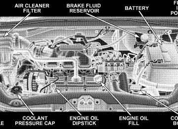
3.3L ENGINE COMPARTMENT
3.8L ENGINE COMPARTMENT
MAINTAINING YOUR VEHICLE 433
434 MAINTAINING YOUR VEHICLE
4.0L ENGINE COMPARTMENT
ONBOARD DIAGNOSTIC SYSTEM — OBD II Your vehicle is equipped with a sophisticated onboard diagnostic system called OBD II. This system monitors the performance of the emissions, engine, and automatic transmission control systems. When these systems are operating properly, your vehicle will provide excellent performance and fuel economy, as well as engine emis- sions well within current government regulations. If any of these systems require service, the OBD II system will turn on the “Malfunction Indicator Light.” It will also store diagnostic codes and other information to assist your service technician in making repairs. Al- though your vehicle will usually be drivable and not need towing, see your authorized dealer for service as soon as possible.
MAINTAINING YOUR VEHICLE 435
CAUTION!
† Prolonged driving with the “Malfunction Indica- tor Light” on could cause further damage to the emission control system. It could also affect fuel economy and driveability. The vehicle must be serviced before any emissions tests can be per- formed. † If the “Malfunction Indicator Light” is flashing while the engine is running, severe catalytic con- verter damage and power loss will soon occur. Immediate service is required.
436 MAINTAINING YOUR VEHICLE
Loose Fuel Filler Cap Message — gASCAP Should the “Loose Fuel Filler Cap” or “gASCAP” mes- sage appear, there may be a problem in the evaporative system. Before taking the vehicle into an authorized dealer, check first to see if the fuel filler cap is possibly loose, improperly installed, or damaged. A loose fuel filler cap message will be displayed in the instrument cluster. Tighten the gas cap until a 9clicking9 sound is heard. This is an indication that the gas cap is properly tightened. Press the odometer reset button to turn the message off. If the problem persists, the message will appear the next time the vehicle is started. If the problem is detected twice in a row, the system will turn on the Malfunction Indicator Light (MIL). Resolving the prob- lem will turn the MIL light off. Take your vehicle in to an authorized dealer.
EMISSIONS INSPECTION AND MAINTENANCE PROGRAMS In some localities, it may be a legal requirement to pass an inspection of this vehicle’s emissions control system. Failure to pass could prevent vehicle registration.
For states that require an Inspection and Mainte- nance (I/M), this check verifies the Malfunction Indicator Light (MIL) is functioning and is not on when the engine is running, and that the OBD II system is ready for testing. Normally, the OBD II system will be ready. The OBD II system may not be ready if the vehicle was recently serviced, recently had a dead battery, or a battery replace- ment. If the OBD II system should be determined not ready for the I/M test, the vehicle may fail the test.
This vehicle has a simple ignition key-actuated test, which you can use prior to going to the test station. To check if this vehicle’s OBD II system is ready, you must do the following: 1. Insert the ignition key into the ignition switch. 2. Turn the ignition to the ON position, but do not crank or start the engine. 3. If you crank or start the engine, you will have to start this test over. 4. As soon as you turn the ignition key to the ON position, you will see the MIL symbol come on as part of a normal bulb check. 5. Approximately 15 seconds later, one of two things will happen:
a. The MIL will flash for about 10 seconds and then return to being fully illuminated until you turn OFF
MAINTAINING YOUR VEHICLE 437
the ignition key or start the engine. This means that the vehicle’s OBD II system is not ready and you should not proceed to the I/M station. b. The MIL will not flash at all and will remain fully illuminated until you turn OFF the ignition key or start the engine. This means that the vehicle’s OBD II system is ready, and you can proceed to the I/M station.
If the OBD II system is not ready, you should see an authorized dealer or repair facility. If this vehicle was recently serviced or had a battery failure or replacement, you may need to do nothing more than drive the vehicle as you normally would in order for the OBD II system to update. A recheck with the above test routine may then indicate that the system is now ready. Regardless of whether the vehicle’s OBD II system is ready or not ready, if the MIL is illuminated during normal vehicle operation, you should have the vehicle
438 MAINTAINING YOUR VEHICLE
serviced before going to the I/M station. The I/M station can fail the vehicle because the MIL is on with the engine running.
NOTE: systems can result against you.
Intentional tampering with emissions control in civil penalties being assessed
REPLACEMENT PARTS Use of genuine Mopart parts for normal/scheduled maintenance and repairs is highly recommended to en- sure the designed performance. Damage or failures caused by the use of non-Mopart parts for maintenance and repairs will not be covered by the manufacturer’s warranty.
AUTHORIZED DEALER SERVICE Your authorized dealer has the qualified service person- nel, special tools, and equipment to perform all service operations in an expert manner. Service manuals are available which include detailed service information for your vehicle. Refer to these service manuals before attempting any procedure yourself.
WARNING!
You can be badly injured working on or around a motor vehicle. Only do service work for which you have the knowledge and the proper equipment. If you have any doubt about your ability to perform a service job, take your vehicle to a competent mechanic.
MAINTENANCE PROCEDURES The pages that follow contain the required maintenance services determined by the engineers who designed your vehicle. Besides the maintenance items for which there are fixed maintenance intervals, there are other items that should operate satisfactorily without periodic maintenance. However, if a malfunction of these items does occur, it could adversely affect the engine or vehicle performance. These items should be inspected if a malfunction is observed or suspected.
MAINTAINING YOUR VEHICLE 439
ENGINE OIL
Checking Oil Level To assure proper engine lubrication, the engine oil must be maintained at the correct level. Check the oil level at regular intervals, such as every fuel stop. The best time to check the engine oil level is about five minutes after a fully warmed engine is shut off or before starting the engine after it has sat overnight. Checking the oil while the vehicle is on level ground will improve the accuracy of the oil level readings. Maintain the oil level between the MIN and MAX markings on the dipstick. Adding one quart of oil when the reading is at the MIN mark will result in a MAX reading on these engines.
440 MAINTAINING YOUR VEHICLE
Engine Oil Dipstick
CAUTION!
Overfilling or underfilling will cause oil aeration or loss of oil pressure. This could damage your engine.
Change Engine Oil The oil change indicator system will remind you that it is time to take your vehicle in for scheduled maintenance. Refer to “Maintenance Schedule” in Section 8 of this manual for information on this system. NOTE: Under no circumstances should oil change intervals exceed 6,000 miles (10 000 km) or six months, whichever occurs first.
Engine Oil Selection For best performance and maximum protection under all types of operating conditions, the manufacturer only recommends engine oils that are API certified and meet the requirements of DaimlerChrysler Material Standard MS-6395.
American Petroleum Institute (API) Engine Oil Identification Symbol
This symbol means that the oil has been certified by the American Petroleum Institute (API). The manufacturer only recommends API Certified engine oils.
Engine Oil Viscosity (SAE Grade) — 3.3L & 3.8L Gasoline Engines SAE 5W-20 engine oil is recommended for all operating temperatures. This engine oil improves low temperature starting and vehicle fuel economy. Your engine oil filler cap also shows the recommended engine oil viscosity for your vehicle.
MAINTAINING YOUR VEHICLE 441
For information on engine oil filler cap location, refer to the Engine Compartment illustration in this section. Lubricants which do not have both, the engine oil certi- fication mark and the correct SAE viscosity grade num- ber should not be used. Engine Oil Viscosity (SAE Grade) — 4.0 Liter Engines SAE 10W-30 engine oil is preferred for all operating temperatures. The engine oil filler cap also shows the recommended engine oil viscosity for your vehicle. Lubricants which DO NOT have both, the engine oil certification mark and the correct SAE viscosity grade number should not be used.
442 MAINTAINING YOUR VEHICLE
Synthetic Engine Oils You may use synthetic engine oils provided the recom- mended oil quality requirements are met, and the recom- mended maintenance intervals for oil and filter changes are followed. Materials Added to Engine Oil The manufacture strongly recommends against the addi- tion of any additives (other than leak detection dyes) to the engine oil. Engine oil is an engineered product and its performance may be impaired by supplemental addi- tives. Disposing of Used Engine Oil And Oil Filters Care should be taken in disposing of used engine oil and oil filters from your vehicle. Used oil and oil filters, indiscriminately discarded, can present a problem to the environment. Contact your authorized dealer, service
station, or governmental agency for advice on how and where used oil and oil filters can be safely discarded in your area. ENGINE OIL FILTER The engine oil filter should be replaced at every engine oil change. Engine Oil Filter Selection The manufacturer’s engines have a full-flow type oil filter. Use a filter of this type for replacement. The quality of replacement filters varies considerably. Only high quality filters should be used to assure most efficient service. Mopart Engine Oil Filters are a high quality oil filter and are recommended.
DRIVE BELT At the mileage indicated in the maintenance schedule, replace the drive belt with a new drive belt. NOTE: The drive belt must be routed correctly to ensure proper drive function. SPARK PLUGS Spark plugs must fire properly to assure engine perfor- mance and emission control. New plugs should be in- stalled at the specified mileage. The entire set should be replaced if there is any malfunction due to a faulty spark plug. Malfunctioning spark plugs can damage the cata- lytic converter. For proper type of replacement spark plugs, refer to Fluids, Lubricants and Genuine Parts for correct spark plug type.
MAINTAINING YOUR VEHICLE 443
ENGINE AIR CLEANER Refer to the “Maintenance Schedule” in Section 8 of this manual for engine air cleaner filter maintenance inter- vals. NOTE: Be sure to follow the “dusty or off-road condi- tions” maintenance interval if applicable.
WARNING!
The air induction system (air cleaner, hoses, etc.) can provide a measure of protection in the case of engine backfire. Do not remove the air induction system (air cleaner, hoses, etc.) unless such removal is necessary for repair or maintenance. Make sure that no one is near the engine compartment before starting the vehicle with the air induction system (air cleaner, hoses, etc.) removed. Failure to do so can result in serious personal injury.
444 MAINTAINING YOUR VEHICLE
CATALYTIC CONVERTER The catalytic converter requires the use of unleaded fuel only. Leaded gasoline will destroy the effectiveness of the catalyst as an emission control device. Under normal operating conditions, the catalytic con- verter will not require maintenance. However, it is im- portant to keep the engine properly tuned to assure proper catalyst operation and prevent possible catalyst damage.
CAUTION!
Damage to the catalytic converter can result if your vehicle is not kept in proper operating condition. In the event of engine malfunction, particularly involv- ing engine misfire or other apparent loss of perfor- mance, have your vehicle serviced promptly. Contin- ued operation of your vehicle with a severe malfunction could cause the converter to overheat, resulting in possible damage to the converter and the vehicle.
NOTE: systems can result against you.
Intentional tampering with emissions control in civil penalties being assessed
WARNING!
A hot exhaust system can start a fire if you park over materials that can burn. Such materials might be grass or leaves coming into contact with your exhaust system. Do not park or operate your vehicle in areas where your exhaust system can contact anything that can burn.
In unusual situations involving grossly malfunctioning engine operation, a scorching odor may indicate severe and abnormal catalyst overheating. If this occurs, the vehicle should be stopped, the engine shut off and the vehicle allowed to cool. Thereafter, service, including a tune-up to manufacturer’s specifications, should be ob- tained immediately.
MAINTAINING YOUR VEHICLE 445
To minimize the possibility of catalyst damage: † Do not shut off the engine or interrupt the ignition when the transaxle is in gear and the vehicle is in motion. † Do not try to start engine by pushing or towing the † Do not idle the engine with any spark plug wires disconnected or removed, such as when diagnostic testing, or for prolonged periods during very rough idling or malfunctioning operating conditions.
vehicle.
446 MAINTAINING YOUR VEHICLE
Exhaust System The best protection against carbon monoxide entry into the vehicle body is a properly maintained engine exhaust system. Whenever a change is noticed in the sound of the exhaust system, when exhaust fumes can be detected inside the vehicle, or when the underside or rear of the vehicle is damaged, have a competent mechanic inspect the com- plete exhaust system and adjacent body areas for broken, damaged, deteriorated, or mispositioned parts. Open seams or loose connections could permit exhaust fumes to seep into the passenger compartment. In addition, inspect the exhaust system each time the vehicle is raised for lubrication or oil change. Replace as required.
WARNING!
Exhaust gases can injure or kill. They contain carbon monoxide (CO) which is colorless and odorless. Breathing it can make you unconscious and can eventually poison you. To avoid breathing CO, refer to “Exhaust Gas” in the Safety Tips section of this manual.
MAINTENANCE-FREE BATTERY The top of the MAINTENANCE-FREE battery is perma- nently sealed. You will never have to add water, nor is periodic maintenance required.
WARNING!
† Battery fluid is a corrosive acid solution and can burn or even blind you. Don’t allow battery fluid to contact your eyes, skin or clothing. Don’t lean over a battery when attaching clamps. If acid splashes in eyes or on skin, flush the area imme- diately with large amounts of water. † Battery gas is flammable and explosive. Keep flame or sparks away from the battery. Don’t use a booster battery or any other booster source with an output greater than 12 volts. Don’t allow cable clamps to touch each other. † Battery posts, terminals and related accessories contain lead and lead compounds. Wash hands after handling.
MAINTAINING YOUR VEHICLE 447
CAUTION!
† It is essential when replacing the cables on the battery that the positive cable is attached to the positive post and the negative cable is attached to the negative post. Battery posts are marked posi- tive (+) and negative (-) and identified on the battery case. Cable clamps should be tight on the terminal posts and free of corrosion. † If a “fast charger” is used while the battery is in the vehicle, disconnect both vehicle battery cables before connecting the charger to battery. Do not use a “fast charger” to provide starting voltage.
448 MAINTAINING YOUR VEHICLE
AIR CONDITIONER MAINTENANCE For best possible performance, your air conditioner should be checked and serviced by an authorized dealer at the start of each warm season. This service should include cleaning of the condenser fins and a system performance check. Drive belt tension should also be checked at this time.
WARNING!