- Download PDF Manual
-
156 UNDERSTANDING THE FEATURES OF YOUR VEHICLE
ESP/TCS Indicator Light The “ESP/TCS Indicator Light” located in the instrument cluster, starts to flash as soon as the tires lose traction and the ESP system becomes active. The “ESP/TCS Indicator Light” also flashes when TCS is active. If the “ESP/TCS Indicator Light” begins to flash during acceleration, ease up on the accelerator and apply as little throttle as possible. Be sure to adapt your speed and driving to the prevailing road conditions.
WARNING!
† Electronic Stability Program (ESP) cannot prevent the natural laws of physics from acting on the vehicle, nor can it increase the traction afforded by prevailing road conditions. † ESP cannot prevent accidents, including those resulting from excessive speed in turns, driving on very slippery surfaces, or hydroplaning. Only a safe, attentive, and skillful driver can prevent accidents. † The capabilities of an ESP-equipped vehicle must never be exploited in a reckless or dangerous manner which could jeopardize the user’s safety or the safety of others.
ESP Operating Modes The ESP system has 2 available operating modes. ESP ON This is the normal operating mode for ESP. Whenever the vehicle is started the ESP system will be in this mode. This mode should be used for most driving situations. ESP should only be turned to “Partial ESP” for specific reasons as noted below.
UNDERSTANDING THE FEATURES OF YOUR VEHICLE 157
Traction Control Switch
PARTIAL ESP This mode is entered by momentarily depressing the “ESP OFF” button. When in “Partial ESP” mode, the TCS portion of ESP has been disabled, the thresholds for ESP activation are
158 UNDERSTANDING THE FEATURES OF YOUR VEHICLE
raised, and the “ESP/TCS Indicator Light” will be illu- minated. This mode is intended to be used for a more spirited driving experience, or if the vehicle is in deep snow, sand, or gravel conditions and more wheel spin that ESP would normally allow is required.
To turn ESP on again, momentarily depress the “ESP OFF” button.
WARNING!
In the Partial ESP mode, the engine torque reduction and stability features are desensitized. Therefore, the enhanced vehicle stability offered by ESP is unavailable.
NOTE: To improve the vehicle’s traction when driving with snow chains, or starting off in deep snow, sand or gravel, it may be desirable to switch to the “Partial ESP” mode by pressing the “ESP OFF” button. Once the
situation requiring ESP to be switched to the “Partial ESP” mode is overcome, turn ESP back on by momen- tarily depressing the “ESP OFF” button. This may be done while the vehicle is in motion. ESP/BAS Warning Light and ESP/TCS Indicator Light The malfunction indicator for the ESP is combined with the BAS indicator. The yellow “ESP/BAS Warning Lamp” and the yellow “ESP/TCS Indicator Light” in the instrument cluster both come on when the ignition switch is turned to the “ON” position. They should both go out with the engine running. If the “ESP/BAS Warn- ing Lamp” comes on continuously with the engine running, a malfunction has been detected in either the ESP or BAS system, or both. If this light remains on after several ignition cycles, and the vehicle has been driven several miles at speeds greater than 30 mph (48 km/h), see your authorized dealer as soon as possible to have the problem diagnosed and corrected.
NOTE: † The “ESP Indicator Light” and the “ESP/BAS Warning Light” come on momentarily each time the ignition switch is turned ON. † Each time the ignition is turned ON, the ESP System † The ESP Control System will make buzzing or clicking sounds when it is active. This is normal; the sounds will stop when ESP becomes inactive following the maneuver that caused the ESP activation.
will be ON even if it was turned off previously.
ADJUSTABLE PEDALS — IF EQUIPPED This feature allows both the brake and accelerator pedals to move toward or away from the driver to provide improved position with the steering wheel. The adjust- able pedal system is designed to allow a greater range of driver comfort for steering wheel tilt and seat position. The switch is located on the drivers door trim panel next to the power seat switches.
UNDERSTANDING THE FEATURES OF YOUR VEHICLE 159
ADJUSTABLE PEDAL SWITCH
Press the switch forward to move the pedals forward (toward the front of the vehicle). Press the switch rearward to move the pedals rearward (toward the driver). † The pedals can be adjusted with the ignition OFF.
160 UNDERSTANDING THE FEATURES OF YOUR VEHICLE
† The pedals can be adjusted while driving. † The pedals cannot be adjusted when the vehicle is in R (Reverse) or when the Speed Control is ON. A message will be displayed in the Electronic Vehicle Information Center (EVIC) if the pedals are attempted to be ad- justed when the system is locked out (“Adjustable Pedal Disabled — Cruise Control Engaged” or “Ad- justable Pedal Disabled — Vehicle In Reverse”).
If your vehicle is equipped with memory seat NOTE: feature, your remote keyless entry transmitter or memory seat buttons on the driver’s door panel can be used to recall the adjustable pedals to saved positions.
CAUTION!
Do not place any article under the adjustable pedals or impede its ability to move as it may cause damage to the pedal controls. Pedal travel may become lim- ited if movement is stopped by an obstruction in the adjustable pedal’s path.
REAR PARK SENSE SYSTEM — IF EQUIPPED The Rear Park Assist System provides visual and audible indications of the distance between the rear fascia and the detected obstacle when backing up. When backing up the driver should also use the inside rearview and outside mirrors. The Rear Park Assist System will remember the last system state (enabled or disabled) from the last ignition cycle when the ignition is changed to the RUN/ON position.
The Rear Park Assist System can be active only when the transaxle shift lever is in R (Reverse). If the Rear Park Assist System is enabled at this shift position, the system will be active until the vehicle speed is increased to approximately 11 mph (18 km/h) or above. The system will be active again if the vehicle speed is decreased to speeds less than approximately 10 mph (16 km/h). Rear Park Assist Sensors The four Rear Park Assist Sensors, located in the rear fascia, monitor the area behind the vehicle that is within the sensors’ field of view. The monitored area seems oval in shape. The sensors can detect obstacles from approxi- mately 11.8 inches (30 cm) up to 59 inches (150 cm) from the rear fascia in the horizontal direction, depending on the location and orientation of the obstacle and the type of obstacle.
UNDERSTANDING THE FEATURES OF YOUR VEHICLE 161
Rear Park Assist LEDs
162 UNDERSTANDING THE FEATURES OF YOUR VEHICLE
Rear Park Assist Warning Display The Rear Park Assist Warning Display, located in the headliner near the liftgate glass, provides both visual and audible warnings to indicate the distance between the rear fascia and the detected obstacle. When the ignition is changed to the RUN/ON position, the warning display will turn ON all of its LEDs for about 1 second. Each side of the warning display has 6
yellow and 2 red LEDs. The vehicle is close to the obstacle when the red LED is ON.The driver can view the LEDs either through the rear view mirror or by looking at the display above the rear window. The system dimly illuminates the two outer most yellow LEDs when it is ON and detecting no obstacles. The following chart shows the warning display operation when the system is detecting an obstacle:
WARNING DISPLAY DISTANCES
DISPLAY LED
OBSTACLE DISTANCE FROM:
LED COLOR
AUDIBLE SIGNAL
UNDERSTANDING THE FEATURES OF YOUR VEHICLE 163
1st LED 2nd LED 3rd LED 4th LED 5th LED 6th LED 7th LED 8th LED
REAR CORNERS
31.5 in. (80 cm) 25.5 in. (65 cm) 20 in. (50 cm) 16 in. (40 cm) 6 in. (15 cm)
REAR CENTER 78.7 in. (200 cm) 51.2 in. (130 cm) 45.3 in. (115 cm) 39.3 in. (100 cm) 33.5 in. (85 cm) 27.6 in. (70 cm)
19.7 in. (50 cm) Red
11.8 in. (30 cm)
NOTE: The Rear Park Sense System will MUTE the radio, if on, when the audible warning is activated.
Yellow Yellow Yellow Yellow Yellow Yellow Red Red
Yes, half second
None None None None None
Yes, intermittent Yes, continuous
164 UNDERSTANDING THE FEATURES OF YOUR VEHICLE
WARNING!
† Drivers must be careful when backing up even when using the Rear Park Sense System. Always check carefully behind your vehicle, and be sure to check for pedestrians, animals, other vehicles, obstructions, or blind spots before backing up. You are respon- sible for the safety of your surroundings and must continue to pay attention while backing up. Failure to do so can result in serious injury or death. † Before using the Rear Park Sense System, it is strongly recommended that the ball mount and hitch ball assembly be disconnected from the vehicle when the vehicle is not used for towing. Failure to do so can result in injury or damage to vehicles or obstacles because the hitch ball will be much closer to the obstacle than the rear fascia when the warning display turns the red LEDs ON. Also, the sensors could detect the ball mount and hitch ball assembly, depending on its size and shape, giving a false indication that an obstacle is behind the vehicle.
CAUTION!
† To avoid vehicle damage the Rear Park Sense System should only be used as a parking aid and is unable to recognize every obstacle, including small objects. Parking curbs might be temporarily detected or not detected at all. Obstacles located above or below the sensors will not be detected when they are in close proximity to the rear of the vehicle. † To avoid vehicle damage the vehicle must be driven slowly when using the Rear Park Sense System to be able to stop in time when an obstacle is detected. It is recommended that the driver look over his/her shoulder when using the Rear Park Sense System.
NOTE: † Ensure that the rear bumper is free of dirt and debris † Jackhammers, large trucks, and other vibrations could
to keep the system operating properly.
affect the performance of the system.
If “Service Park Sense System” appears in the Electronic Vehicle Information Center (EVIC) after making sure the rear bumper is clean please see your authorized dealer. Enable/Disable the Rear Park Assist System — If Equipped The Rear Park Assist System can be enabled and disabled with a switch located on the switch bank of the instru- ment panel. When the switch is pressed to disable the system, the instrument cluster will display the 9PARK ASSIST DISABLED9 message. Refer to “Electronic Vehicle Information Center (EVIC)” in Section 4 of this manual. When the shift lever is changed to R (Reverse) and the
UNDERSTANDING THE FEATURES OF YOUR VEHICLE 165
system is disabled, the instrument cluster will actuate a single chime, once per ignition cycle, and it will display the message. The Rear Park Assist Switch LED will be ON when the Rear Park Assist System is disabled or defective. The Rear Park Assist Switch LED will be OFF when the system is enabled. The system can be turned on or off through the Electronic Vehicle Information Center (EVIC), if equipped. For details, refer to “Personal Settings (Customer Program- mable Features)” under “Electronic Vehicle Information enter (EVIC)” in Section 4 of this manual. Service the Rear Park Assist System When the Rear Park Assist System is defective, the instrument cluster will actuate a single chime, once per ignition cycle, and it will display the (SERVICE PARK ASSIST SYSTEM( message. Refer to “Electronic Vehicle Information Center (EVIC)” in Section 4 of this manual.
166 UNDERSTANDING THE FEATURES OF YOUR VEHICLE
If (SERVICE PARK ASSIST SYSTEM( appears in the Electronic Vehicle Information Center (EVIC) after mak- ing sure the rear bumper is clean please see your autho- rized dealer. Cleaning the Rear Park Assist System Clean the Rear Park Assist Sensors with water, car wash soap and a soft cloth. Do not use rough or hard cloths. Do not scratch or poke the sensors, otherwise, you could damage the sensors.
REAR CAMERA — IF EQUIPPED Your vehicle may be equipped with a Rear Camera system that allows you to see an on-screen image (located in the center of the instrument cluster) of the rear of your vehicle whenever it is put into R (Reverse). The camera is located in the light bar over the rear license plate.
NOTE: Refer to “Setting Display Properties” under “System Settings” in the Navigation User’s Manual for instructions regarding navigation screen brightness ad- justments. Use the following steps to access the Rear Backup Cam- era feature: 1. Start the engine. 2. Place shift lever in R (Reverse). 3. Wait one to two seconds, and the camera view will display on the instrument cluster. NOTE: The camera view will display only while the vehicle is in R (Reverse). 4. Perform a visual check of the rear area. NOTE: CHECK ENTIRE SURROUNDINGS before backing up.
5. Backup as necessary. 6. Place the sift lever in P (Park) or D (Drive) to exit the Rear Backup Camera system.
WARNING!
Drivers must be careful when backing up even when using the Rear Camera System. Always check care- fully behind your vehicle, and be sure to check for pedestrians, animals, other vehicles, obstructions, or blind spots before backing up. You are responsible for the safety of your surroundings and must con- tinue to pay attention while backing up. Failure to do so can result in serious injury or death.
UNDERSTANDING THE FEATURES OF YOUR VEHICLE 167
CAUTION!
† To avoid vehicle damage the Rear Camera System should only be used as a parking aid and is unable to view every obstacle, or object in your drive path. † To avoid vehicle damage the vehicle must be driven slowly when using the Rear Camera Sys- tem to be able to stop in time when an obstacle is seen. It is recommended that the driver look fre- quently over his/her shoulder when using the Rear Camera System.
If snow, ice, mud, or anything else builds up on NOTE: the camera lens, clean the lens, rinse with water, and dry with a soft cloth. Do not cover the lens.
168 UNDERSTANDING THE FEATURES OF YOUR VEHICLE
OVERHEAD CONSOLE — IF EQUIPPED The overhead console can contain courtesy/reading lights, an optional universal garage door opener (HomeLinkt), storage for sunglasses, optional power sunroof switches and an optional power liftgate switch.
Overhead Console
Courtesy/Reading Lights
At the forward end of the console are two courtesy/ reading lights. Press the lens to turn these lights on. Press a second time to turn the lights off. The lights also turn on when a front door, a rear door or the liftgate is opened. The lights will also turn on when the unlock button on the remote keyless entry transmitter is pressed. Sunglasses Storage At the rear of the overhead console, a compartment is provided for the storage of a pair of sunglasses. Press the door latch to open the compartment. The door will slowly rotate to an open position.
POWER SUNROOF — IF EQUIPPED The power sunroof buttons are located between the sun visors on the overhead console.
Power Sunroof buttons
UNDERSTANDING THE FEATURES OF YOUR VEHICLE 169
Press and hold the “OPEN” button rearward to fully open the sunroof. The sunroof can be stopped at any position between closed and full open. Momentarily pressing the “OPEN” button rearward will activate the Express Open Feature, causing the sunroof to open automatically. Press and hold the “VENT” button to open the vent. The sunroof can be stopped at any position between closed and full vent. To close the sunroof from the vent position, press and hold the “CLOSE” button forward. Releasing the button will stop the movement of the sunroof and the sunroof will remain in the partial vent position until the button is pushed forward again. NOTE: The power sunroof buttons remain active for up to 45 seconds after the ignition button has been turned off. Opening either front door will cancel this feature.
170 UNDERSTANDING THE FEATURES OF YOUR VEHICLE
Express Open Feature The sunroof is equipped with an intermediate stop or comfort stop position. This feature is designed to elimi- nate wind buffeting at vehicle speeds between 20-40 mph (32-64 km/h). To operate this feature, momentarily press the “OPEN” button rearward to activate the Express Open Feature and the glass will automatically stop at the comfort stop position. Pressing the button rearward again will fully open the sunroof. During the Express Open operation, any movement of the button will stop the sunroof and it will remain in a partial open position. Again, momentarily pressing the button rearward will activate the Express Open Feature.
To close the sunroof, press and hold the “CLOSE” button forward. Again, any release of the button will stop the movement and the sunroof will remain in a partial open condition until the button is pushed forward again. The sunshade can be opened manually. It will also open as the sunroof opens. The sunshade cannot be closed if the sunroof is open.
WARNING!
† NEVER leave children alone in a vehicle. Occu- pants, particularly unattended children, can be- come entrapped by the power sunroof while oper- ating the power sunroof switch. Such entrapment may result in serious injury or death. Don’t leave the keys in the ignition. A child could operate power windows, other controls, or move the ve- hicle † In an accident, there is a greater risk of being thrown from a vehicle with an open sunroof. You could also be seriously injured or killed. Always fasten your seat belt properly and make sure all passengers are properly secured too. † Do not allow small children to operate the sunroof. Never allow fingers or other body parts, or any object to project through the sunroof opening. Injury may result.
UNDERSTANDING THE FEATURES OF YOUR VEHICLE 171
Wind Buffeting Wind buffeting can be described as the perception of pressure on the ears or a helicopter type sound in the ears. Your vehicle may exhibit wind buffeting with the windows down, or the sunroof (if equipped) in certain open or partially open positions. This is a normal occur- rence and can be minimized. If the buffeting occurs with the rear windows open, open the front and rear windows together to minimize the buffeting. If the buffeting occurs with the sunroof open, adjust the sunroof opening to minimize the buffeting or open any window. Sunroof Comfort Position — If Equipped If equipped, some model sunroofs will stop at a prede- termined comfort position — not allowing the sunroof to open to the full retracted glass position. The comfort position stops the sunroof glass at approximately 3/4
open position. This will allow for minimal wind buffet- ing.172 UNDERSTANDING THE FEATURES OF YOUR VEHICLE
Sunroof Maintenance Use only a non-abrasive cleaner and a soft cloth to clean the glass panel.
ELECTRICAL POWER OUTLETS There are two 12 volt power outlets located on the instrument panel below the radio. The driver’s side outlet is controlled by the ignition switch and the passenger side outlet is connected directly to the battery. The driver’s side outlet will also operate a conventional cigar lighter unit (if equipped with an optional Smoker’s Package).
Front Power Outlets
A third outlet is located on the back of the front center console near the floor, and is also controlled by the ignition switch. A fourth outlet is located on the driver’s side, in the rear cargo area and is also controlled by the ignition switch.
The outlets include tethered caps labeled with a key or battery symbol indicating the power source. The passen- ger side instrument panel and center console outlets are powered directly from the battery, items plugged into these outlets may discharge the battery and/or prevent engine starting. The passenger side and center console outlets are pro- tected by an automatic reset circuit breaker. The auto- matic circuit breaker restores power when the overload is removed. If desired, the fourth power outlet in the rear NOTE: cargo area can be converted by your authorized dealer to provide power with the ignition switch in the OFF position.
UNDERSTANDING THE FEATURES OF YOUR VEHICLE 173
Electrical Outlet Use With Engine Off
CAUTION!
† Many accessories that can be plugged in draw power from the vehicle’s battery, even when not in use (i.e. cellular phones, etc.). Eventually, if plugged in long enough, the vehicle’s battery will discharge suffi- ciently to degrade battery life and/or prevent engine starting. † Accessories that draw higher power (i.e. coolers, vacuum cleaners, lights, etc.), will degrade the battery even more quickly. Only use these intermittently and with greater caution. † After the use of high power draw accessories, or long periods of the vehicle not being started (with accesso- ries still plugged in), the vehicle must be driven a sufficient length of time to allow the alternator to recharge the vehicle’s battery. † Power outlets are designed for accessory plugs only. Do not hang any type of accessory or accessory bracket from the plug. Improper use of the power outlet can cause damage.
174 UNDERSTANDING THE FEATURES OF YOUR VEHICLE
CUPHOLDERS
Front Seat Cupholders The cupholders are located in the forward edge of the center console. Push down on the forward edge of the console to release the cupholders. Press the cover up when the cupholders are no longer needed.
Second Row Seat Cupholders On vehicles equipped with five passenger seating the second row seat cupholders are located in middle of the seatback armrest. Pull down on the armrest to access the cupholders. Push the armrest up when the cupholders are no longer needed.
Six Passenger Seating Cupholders
Five Passenger Seating Cupholders
On vehicles equipped with six passenger seating the second row seat cupholders are located in the forward edge of the center console located between the second row seats. Push down on the forward edge of the console to release the cupholders. Press the cover up when the cupholders are no longer needed. Third Row Seat Cupholders — If Equipped There are cupholders located in each rear trim panel for the third row seat passengers.
STORAGE
Console Features The center consoles may be equipped with a tissue holder mounted on the underside of the cover. The bottom of the console bins may also have built in holders for compact discs or cassette tapes.
UNDERSTANDING THE FEATURES OF YOUR VEHICLE 175
Rear Cargo Storage Bin — If Equipped The storage bin is located in the floor of the rear cargo area. To open lift up on the handle.
Rear Storage Bin
176 UNDERSTANDING THE FEATURES OF YOUR VEHICLE
Retractable Cargo Area Cover — If Equipped To cover the cargo area: 1. Fold down the third row seatbacks. 2. Unfold the cargo cover extensions and lock into place. 3. Insert the pins on the ends of the cover into the slots located on the trim panel behind the second row seat- backs. 4. Grasp the center portion of the cover flap. Pull it over the cargo area. 5. Insert the pins on the ends of the cover flap into the slots on the rear trim panel. 6. The liftgate may be opened or closed with the cargo cover in place.
WARNING!
In an accident a cargo cover loose in the vehicle could cause injury. It could fly around in a sudden stop and strike someone in the vehicle. Do not store the cargo cover on the cargo floor or in the passenger compart- ment. Remove the cover from the vehicle when taken from its mounting. Do not store in the vehicle.
Stowed Position 1. Fold down the third row seatbacks. 2. Fold the cargo cover extensions to their stowed posi- tion and lock into place. 3. Insert the pins on the ends of the cover into the slots located on the trim panel behind the third row seatbacks.
4. Grasp the center portion of the cover flap. Pull it over the cargo area. 5. Insert the pins on the ends of the cover flap into the slots on the rear trim panel. 6. The liftgate may be opened or closed with the cargo cover in place. Cargo Tie-Down Hooks The tie-downs located on cargo area floor and on the rear trim panels should be used to safely secure loads when vehicle is moving.
UNDERSTANDING THE FEATURES OF YOUR VEHICLE 177
WARNING!
† Cargo tie-down hooks are not safe anchors for a child seat tether strap. In a sudden stop or collision a hook could pull loose and allow the child seat to come loose. A child could be badly injured. Use only the anchors provided for child seat tethers. † The weight and position of cargo and passengers can change the vehicle center of gravity and ve- hicle handling. To avoid loss of control resulting in personal injury, follow these guidelines for loading your vehicle:
† Always place cargo evenly on the cargo floor. Put heavier objects as low and as far forward as possible.
178 UNDERSTANDING THE FEATURES OF YOUR VEHICLE
† Place as much cargo as possible in front of the rear axle. Too much weight or improperly placed weight over or behind the rear axle can cause the rear of the vehicle to sway. † Do not pile luggage or cargo higher than the top of the seatback. This could impair visibility or become a dangerous projectile in a sudden stop or collision.
WARNING!
To help protect against personal injury, passengers should not be seated in the rear cargo area. The rear cargo space is intended for load carrying purposes only, not for passengers, who should sit in seats and use seat belts.
ROOF LUGGAGE RACK — IF EQUIPPED The crossbars and siderails are designed to carry the weight on vehicles equipped with a luggage rack. The load must not exceed 150 lbs (68 kg), and should be uniformly distributed over the luggage rack crossbars.
Roof Rack
Distribute cargo weight evenly on the roof rack crossbars. The roof rack does not increase the total load carrying capacity of the vehicle. Be sure the total load of cargo inside the vehicle plus that on the external rack does not exceed the maximum vehicle load capacity. To move the cross bars, press the upper edge of each cross bar button, then move the cross bar to the desired position, keeping the crossbars parallel to the rack frame. This is can be done with one person standing on each side of the vehicle, moving the cross bar at the same time. Once the cross bar is in place, press the lower edge of the cross bar button to lock it into position.
UNDERSTANDING THE FEATURES OF YOUR VEHICLE 179
Attempt to move the crossbar again to ensure that it has properly locked into position. NOTE: To reduce the amount of wind noise when the cross bars are not in use, move both cross bars next to each other towards the rear of the vehicle in the rear most position. The tie down holes on the cross bar ends should always be used to tie down the load. Check the straps frequently to be sure that the load remains securely attached.
180 UNDERSTANDING THE FEATURES OF YOUR VEHICLE
CAUTION!
WARNING!
† Crossbars should remain equally spaced or parallel at any luggage rack position for proper function. Noncompliance could result in damage to the lug- gage rack, cargo and/or vehicle. † To avoid damage to the roof rack and vehicle, do not exceed the maximum roof rack load capacity of 150
lbs (68 kg). Always distribute heavy loads as evenly as possible and secure the load appropriately. † Long loads which extend over the windshield, such as wood panels or surfboards, or loads with large frontal area should be secured to both the front and rear of the vehicle. † Travel at reduced speeds and turn corners carefully when carrying large or heavy loads on the roof rack. Wind forces, due to natural causes or nearby truck traffic, can add sudden upward lift to loads. This is especially true on large flat loads and may result in damage to the cargo or your vehicle.Cargo must be securely tied before driving your ve- hicle. Improperly secured loads can fly off the vehicle, particularly at high speeds, resulting in personal in- jury or property damage. Follow the Roof Rack Cau- tions when carrying cargo on your roof rack.
LOAD LEVELING SYSTEM The automatic load leveling system will provide a level riding vehicle under most passenger and cargo loading conditions. A hydraulic pump contained within the shock absorbers raises the rear of the vehicle to the correct height. It takes approximately 1 mile (1.6 km) of driving for the leveling to complete depending on road surface conditions. If the leveled vehicle is not moved for approximately 15
hours, the leveling system will bleed itself down. The vehicle must be driven to reset the system.UNDERSTANDING YOUR INSTRUMENT PANEL
CONTENTS
m Instrument Panel And Controls . . . . . . . . . . . . . 184
m Base Instrument Cluster . . . . . . . . . . . . . . . . . . 185
m Premium Instrument Cluster . . . . . . . . . . . . . . . 186
m Instrument Cluster Descriptions . . . . . . . . . . . . 187
m Electronic Vehicle Information Center (EVIC) —If Equipped . . . . . . . . . . . . . . . . . . . . . . . . . . . 199
N Oil Change Required . . . . . . . . . . . . . . . . . . . 202
N Customer Programmable Features —If Equipped . . . . . . . . . . . . . . . . . . . . . . . . . 203
N Compass Display — If Equipped . . . . . . . . . . 207N Mini-Trip Functions — If Equipped . . . . . . . . 208
m Setting The Analog Clock . . . . . . . . . . . . . . . . . 209
m Electronic Digital Clock . . . . . . . . . . . . . . . . . . 209
N Clock Setting Procedure . . . . . . . . . . . . . . . . . 210
m Radio General Information . . . . . . . . . . . . . . . . 210
N Radio Broadcast Signals . . . . . . . . . . . . . . . . . 210
N Two Types Of Signals . . . . . . . . . . . . . . . . . . 211
N Electrical Disturbances . . . . . . . . . . . . . . . . . . 211
N AM Reception . . . . . . . . . . . . . . . . . . . . . . . 211182 UNDERSTANDING YOUR INSTRUMENT PANEL
N FM Reception . . . . . . . . . . . . . . . . . . . . . . . . 211
m Sales Code RAH — AM & FM Stereo Radio With
CD Player And CD/DVD Changer Controls . . . . 212
N Radio Operation . . . . . . . . . . . . . . . . . . . . . . 212
N CD Player Operation . . . . . . . . . . . . . . . . . . . 216
N CD/DVD Changer Operation . . . . . . . . . . . . . 218
N Notes On Playing MP3 Files . . . . . . . . . . . . . 218
N Operation Instructions - (CD Mode For MP3Audio Play)
. . . . . . . . . . . . . . . . . . . . . . . . . 220
m Sales Code REV — AM & FM Stereo Radio With
CD Player And CD/DVD Changer Controls . . . . 222
N Radio Operation . . . . . . . . . . . . . . . . . . . . . . 222
N CD Player Operation . . . . . . . . . . . . . . . . . . . 226
N CD/DVD Changer Operation . . . . . . . . . . . . . 228N Notes On Playing MP3 Files N Operation Instructions - (CD Mode For MP3
. . . . . . . . . . . . . 228
Audio Play)
. . . . . . . . . . . . . . . . . . . . . . . . . 230
N Operating Instructions — MP3 Player, Portable
Walkman . . . . . . . . . . . . . . . . . . . . . . . . . . . 231
N Operating Instructions — Video
Games/Camcorders
. . . . . . . . . . . . . . . . . . . 231
m 6 Disc CD/DVD Changer (RDV) — If Equipped . 232
N Operating Instructions — CD/DVD Changer . . 233
N Eject (EJT) Button . . . . . . . . . . . . . . . . . . . . . 235
N Operating Instructions — Remote Control . . . . 235
N Operating Instructions — Video Screen . . . . . . 239
N Operating Instructions — Headphones . . . . . . 241
N Operating Instructions — Auxiliary Input . . . . 243m Navigation System — If Equipped . . . . . . . . . . . 244
m Satellite Radio — If Equipped . . . . . . . . . . . . . . 245
N ystem Activation . . . . . . . . . . . . . . . . . . . . . . 245
N Electronic Serial Number/Sirius IdentificationNumber (ENS/SID) . . . . . . . . . . . . . . . . . . . . 245
N Selecting Satellite Mode In RBB, RAH, REV
And RBK Radios . . . . . . . . . . . . . . . . . . . . . . 246
N Selecting Satellite Mode In RBP, RBU, RAZ,
RB1 And RBQ Radios . . . . . . . . . . . . . . . . . . 246
N Selecting a Channel . . . . . . . . . . . . . . . . . . . . 247
N Storing And Selecting Pre-Set Channels . . . . . . 247
N Using The PTY (Program Type) Button(If Equipped)
. . . . . . . . . . . . . . . . . . . . . . . . 247
N PTY Button 9Scan9 . . . . . . . . . . . . . . . . . . . . . 247
N PTY Button 9Seek9 . . . . . . . . . . . . . . . . . . . . . 248UNDERSTANDING YOUR INSTRUMENT PANEL 183
N Satellite Antenna . . . . . . . . . . . . . . . . . . . . . . 248
N Reception Quality . . . . . . . . . . . . . . . . . . . . . 248
m Remote Sound System Controls . . . . . . . . . . . . . 249
N Radio Operation . . . . . . . . . . . . . . . . . . . . . . 249
N CD Player . . . . . . . . . . . . . . . . . . . . . . . . . . 249
m CD/DVD Disc Maintenance . . . . . . . . . . . . . . . 250
m Radio Operation And Cellular Phones . . . . . . . . 250
m Climate Controls . . . . . . . . . . . . . . . . . . . . . . . 250N Manual Air Conditioning And Heating
System . . . . . . . . . . . . . . . . . . . . . . . . . . . . . 251
N Mode Control . . . . . . . . . . . . . . . . . . . . . . . . 252
N Manual Air Conditioning Operation . . . . . . . . 256
N Dual-Zone Automatic Temperature Control . . . 259
N Electric Rear Window Defroster . . . . . . . . . . . 269184 UNDERSTANDING YOUR INSTRUMENT PANEL
INSTRUMENT PANEL AND CONTROLS
BASE INSTRUMENT CLUSTER
UNDERSTANDING YOUR INSTRUMENT PANEL 185
186 UNDERSTANDING YOUR INSTRUMENT PANEL
PREMIUM INSTRUMENT CLUSTER
UNDERSTANDING YOUR INSTRUMENT PANEL 187
CAUTION!
Driving with a hot engine cooling system could damage your vehicle. If temperature gauge reads “H”, pull over in a safe area as soon as possible and stop the vehicle. Idle the vehicle with the air condi- tioner turned off until the pointer drops back into the normal range. If the pointer remains on the “H”, and you hear continuous chimes, turn the engine off immediately, and call for service.
INSTRUMENT CLUSTER DESCRIPTIONS
1. Voltage Light
This light monitors the electrical system voltage. The light should turn on momentarily as the engine is started. If the light stays on or turns on while driving, it indicates a problem with the charging system. Immediate service should be obtained. 2. Temperature Gauge The temperature gauge shows engine coolant tempera- ture. Any reading within the normal range indicates that the engine cooling system is operating satisfactorily. The gauge pointer will likely indicate a higher tempera- ture when driving in hot weather, up mountain grades, or when towing a trailer. It should not be allowed to exceed the upper limits of the normal operating range.
188 UNDERSTANDING YOUR INSTRUMENT PANEL
WARNING!
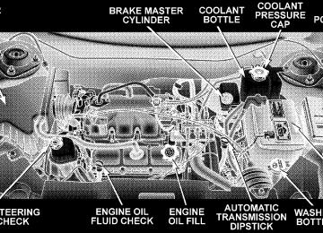
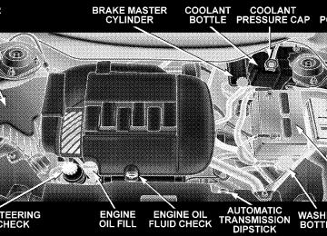
A hot engine cooling system is dangerous. You or others could be badly burned by steam or boiling coolant. You may want to call a service center if your vehicle overheats. If you decide to look under the hood yourself, see Section 7 of this manual. Follow the warnings under the Cooling System Pressure Cap paragraph.
3. Fuel Gauge The pointer shows the level of fuel in the fuel tank when the ignition switch is in the ON position.
The Low Fuel Light will turn on when the fuel level reaches approximately 2 to 4 gallons (7 to 15 liters) this light will remain on until fuel is added.
4. Turn Signal Indicators
The arrow will flash with the exterior turn signal when the turn signal lever is operated.
If the vehicle electronics sense that the vehicle has traveled about one mile with the turn signals on, a chime will sound to alert you to turn the signals off. If either indicator flashes at a rapid rate, check for a defective outside light bulb. 5. Speedometer Indicates vehicle speed. 6. Anti-Lock Brake Light
This light monitors the Anti-Lock Brake Sys- tem. The light will turn on when the ignition switch is turned to the ON position and may stay on for as long as four seconds.
If the ABS light remains on or turns on while driving, it indicates that the Anti-Lock portion of the brake system
is not functioning and that service is required. However, the conventional brake system will continue to operate normally if the BRAKE warning light is not on. If the ABS light is on, the brake system should be serviced as soon as possible to restore the benefits of Anti-Lock brakes. If the ABS light does not turn on when the Ignition switch is turned to the ON position, have the light inspected by an authorized dealer. 7. Brake System Warning Light
This light monitors various brake functions, including brake fluid level and parking brake application. If the brake light turns on, it may indicate that the parking brake is applied, there is a low brake fluid level or there is a problem with the anti-lock brake system. The dual brake system provides a reserve braking capac- ity in the event of a failure to a portion of the hydraulic system. Failure of either half of the dual brake system is
UNDERSTANDING YOUR INSTRUMENT PANEL 189
indicated by the Brake Warning Light which will turn on when the brake fluid level in the master cylinder has dropped below a specified level. The light will remain on until the cause is corrected. NOTE: The light may flash momentarily during sharp cornering maneuvers which change fluid level condi- tions. The vehicle should have service performed. If brake failure is indicated, immediate repair is neces- sary.
WARNING!
Driving a vehicle with the brake light on is danger- ous. Part of the brake system may have failed. It will take longer to stop the vehicle. You could have an accident. Have the vehicle checked immediately.
190 UNDERSTANDING YOUR INSTRUMENT PANEL
Vehicles equipped with Anti-Lock brakes (ABS), are also equipped with Electronic Brake Force Distribution (EBD). In the event of an EBD failure, the Brake Warning Light will turn on along with the ABS Light. Immediate repair to the ABS system is required. The operation of the Brake Warning Light can be checked by turning the ignition switch from the OFF position to the ON position. The light should illuminate for approxi- mately two seconds. The light should then turn off unless the parking brake is applied or a brake fault is detected. If the light does not illuminate, have the light inspected by an authorized dealer. The light also will turn on when the parking brake is applied with the ignition switch in the ON position. NOTE: This light shows only that the parking brake is applied. It does not show the degree of brake application.
8. Electronic Stability Program (ESP) Indicator Light/Traction Control System (TCS) Indicator Light
If this indicator light flashes during accelera- tion, apply as little throttle as possible. While driving, ease up on the accelerator. Adapt your speed and driving to the prevailing road con-
ditions, and do not switch off the ESP, or TCS. NOTE: Extended heavy use of Traction Control may cause the system to deactivate and turn on the Traction Control Light. This is to prevent overheating of the brake system and is a normal condition. The system will remain disabled for about 4 minutes until the brakes have cooled. The system will automatically reactivate and turn off the Traction Control Light.
9. Tachometer The red segments indicate the maximum permissible engine revolutions-per-minute (rpm. x 1000) for each gear range. Before reaching the red area, ease up on the accelerator. 10. Trip Odometer Button Press this button to change the display from odometer to either of the two trip odometer settings. The word TRIP and either “A” or “B” will appear when in the trip odometer mode. Push in and hold the button for two seconds to reset the trip odometer to 0 miles or kilome- ters. The odometer must be in trip mode to reset. 11. Transmission Range Indicator This display indicator shows the automatic transmission gear selection. 12. AutoStick Light This display indicator illuminates when the gearshift lever is moved to the AutoStick position.
UNDERSTANDING YOUR INSTRUMENT PANEL 191
13. Odometer/Trip Odometer The odometer shows the total distance the vehicle has been driven. U.S. federal regulations require that upon transfer of vehicle ownership, the seller certify to the purchaser the correct mileage that the vehicle has been driven. Therefore, if the odometer reading is changed during repair or replacement, be sure to keep a record of the reading before and after the service so that the correct mileage can be determined. The two trip odometers show individual trip mileage. To switch from odometer to trip odometers, press and release the Trip Odometer button. To reset a trip odom- eter, display the desired trip odometer to be reset then push and hold the button until the display resets (ap- proximately 2 seconds). Vehicle Warning Messages When the appropriate conditions exist, vehicle warning messages will display in the odometer.
192 UNDERSTANDING YOUR INSTRUMENT PANEL
If the instrument cluster is equipped with the NOTE: optional Electronic Vehicle Information Center (EVIC), then all warnings will only display in the EVIC. (Refer to “Electronic Vehicle Information Center (EVIC)” in this section for specific messages). gASCAP If the vehicle diagnostic system detects a leak or change in the evaporative system, or the fuel filler cap is loose, improperly installed, or damaged, the words “gASCAP” will display in the odometer. If this occurs, tighten the fuel filler cap properly and press the odometer reset button to turn off the “gASCAP” message. (Refer to “Onboard Diagnostic System — OBDII” in Section 7 of this manual for more information). If the problem con- tinues, the message will appear the next time the vehicle is started. See your authorized dealer service center as soon as possible.
Change Oil Your vehicle is equipped with an engine oil change indicator system. The “Change Oil” message will flash in the instrument cluster odometer for approximately 12
seconds after a single chime has sounded to indicate the next scheduled oil change interval. The engine oil change indicator system is duty cycle based, which means the engine oil change interval may fluctuate dependent upon your personal driving style. Unless reset, this message will continue to display each time you turn the ignition switch to the “ON” position. To turn off the message temporarily, press and release the Trip Odometer button on the instrument cluster. To reset the oil change indicator system (after performing the scheduled maintenance) perform the following proce- dure:1. Turn the ignition switch to the “ON” position (Do not start the engine).
2. Fully depress the accelerator pedal slowly three times within 10 seconds. 3. Turn the ignition switch to the LOCK position.
If the indicator message illuminates when you NOTE: start the vehicle, the oil change indicator system did not reset. If necessary repeat this procedure. 14. Cruise Indicator
This indicator shows that the Speed Control System is ON.
15. Malfunction Indicator Light
This light is part of an onboard diagnostic system called OBD that monitors engine and automatic transmission control systems. The light will illu- minate when the key is in the ON position before engine start. If the bulb does not come on when turning the key from OFF to ON, have the condition checked promptly.
UNDERSTANDING YOUR INSTRUMENT PANEL 193
Certain conditions such as a loose or missing gas cap, poor fuel quality, etc. may illuminate the light after engine start. The vehicle should be serviced if the light stays on through several of your typical driving cycles. In most situations the vehicle will drive normally and will not require towing. The Malfunction Indicator Light flashes to alert you to serious conditions that could lead to immediate loss of power or severe catalytic converter damage. The vehicle should be serviced as soon as possible if this occurs. 16. High Beam Light
This light shows that the headlights are on high beam. Pull the Multi-Function lever towards the steering wheel to switch the headlights from high or low beam.
194 UNDERSTANDING YOUR INSTRUMENT PANEL
17. Navigation Screen/Rear View Camera — If Equipped The navigation system provides maps, turn identifica- tion, selection menus and instructions for selecting a variety of destinations and routes. Refer to your “Navi- gation User’s Manual” for detailed operating instruc- tions. The Rear View Camera system uses the Navigator Screen to display the area behind the vehicle. Camera view will display only while the vehicle is in R (Reverse). 18. Front Fog Light Indicator — If Equipped
This light shows the front fog lights are ON.
19. Oil Pressure Warning Light
This light shows low engine oil pressure. The light should turn on momentarily when the engine is started. If the light turns on while driving, stop the
vehicle and shut off the engine as soon as possible. A continuous chime will sound when this light turns on. Do not operate the vehicle until the cause is corrected. This light does not show how much oil is in the engine. The engine oil level must be checked under the hood. 20. Seat Belt Reminder Light
When the ignition switch is first turned ON, this light will turn on for 5 to 8 seconds as a bulb check. During the bulb check, if the driver’s seat belt is unbuckled, a chime will sound. After the bulb check or when driving, if the driver seat belt remains unbuckled, the Seat Belt Warning Light will flash or remain on continuously. Refer to 9Enhanced Driver Seat Belt Re- minder System (BeltAlert™)9 in the Occupant Restraints section for more information.
21. Tire Pressure Monitoring Telltale Lamp
Each tire, including the spare (if provided), should be checked monthly when cold and inflated to the inflation pressure recommended by the vehicle manufacturer on the vehicle placard or tire inflation pressure label. (If your vehicle has tires of a different size than the size indicated on the vehicle placard or tire inflation pressure label, you should determine the proper tire inflation pressure for those tires.) As an added safety feature, your vehicle has been equipped with a tire pressure monitoring system (TPMS) that illuminates a low tire pressure telltale when one or more of your tires are significantly under-inflated. Ac- cordingly, when the low tire pressure telltale illuminates, you should stop and check your tires as soon as possible, and inflate them to the proper pressure. Driving on a significantly under-inflated tire causes the tire to over- heat and can lead to tire failure. Under-inflation also
UNDERSTANDING YOUR INSTRUMENT PANEL 195
reduces fuel efficiency and tire tread life, and may affect the vehicle’s handling and stopping ability. NOTE: Please note that the TPMS is not a substitute for proper tire maintenance, and it is the driver’s responsi- bility to maintain correct tire pressure, even if underin- flation has not reached the level to trigger illumination of the TPMS low tire pressure telltale. Your vehicle has also been equipped with a TPMS malfunction indicator to indicate when the system is combined with the low tire pressure telltale. When the system detects a malfunction, the telltale will flash for approximately one minute and then remain continuously illuminated. This sequence will continue upon subse- quent vehicle start-ups as long as the malfunction exists. When the malfunction indicator is illuminated, the sys- tem may not be able to detect or signal low tire pressure as intended. TPMS malfunctions may occur for a variety of reasons, including the installation of replacement or
196 UNDERSTANDING YOUR INSTRUMENT PANEL
alternate tires or wheels on the vehicle that prevent the TPMS malfunction telltale after replacing one or more tires or wheels on your vehicle to ensure that the replace- ment or alternate tires and wheels allow the TPMS to continue to function properly. NOTE: Always check the TPMS malfunction telltale after replacing one or more tires or wheels on your vehicle, to ensure that the replacement or alternate tires and wheels allow the TPMS to continue to function properly.
CAUTION!
The TPMS has been optimized for the original equipment tires and wheels (the spare is not moni- tored or equipped with a sensor). TPMS pressures and warning have been established for the tire size equipped on your vehicle. Undesirable system opera- tion or sensor damage may result when using re- placement equipment that is not of the same size, type, and/or style. Aftermarket wheels can cause sensor damage. Do not use aftermarket tire sealants or balance beads if your vehicle is equipped with a TPMS, as damage to the sensors may result.
For additional information on TPMS, refer to Section 5 — Starting and Operating, “Tire Pressure Monitoring Sys- tem” of this manual.
For additional information on Tire Pressures, refer to Section 5 — Starting and Operating, “Tire Inflation Pressures” of this manual. 22. Airbag Light
This light turns on and remains on for 6 to 8
seconds as a bulb check when the ignition switch is first turned ON. If the light is not on during starting, stays on, or turns on while driving, have the system inspected by an authorized dealer as soon as possible. 23. Electronic Vehicle Information Center Display — If Equipped When the appropriate conditions exist, this display shows the Electronic Vehicle Information Center (EVIC) messages. 24. Engine Temperature Warning LightThis light warns of an overheated engine condi- tion. If this light is accompanied by a continuous
UNDERSTANDING YOUR INSTRUMENT PANEL 197
chime, the engine temperature is critically hot, and the vehicle should be turned off immediately. The vehicle should be serviced as soon as possible. 25. Liftgate Ajar — If Equipped
This light turns on if the liftgate is not com- pletely closed.
26. Door Ajar Light — If Equipped
This light turns on if a door is not completely closed.
27. Washer Fluid Light — If Equipped
This light turns on when the washer fluid level falls below approximately 1/4 filled. The light will remain on until fluid is added.
198 UNDERSTANDING YOUR INSTRUMENT PANEL
28. Electronic Stability Program (ESP) Warning Light/Brake Assist System (BAS) Warning Light — If Equipped
The malfunction lamp for the ESP is combined with BAS. The yellow “ESP/BAS Warning Lamp” comes on when the ignition switch is turned to the “ON” position. They should go out with the engine running. If the “ESP/BAS Warning Lamp” comes on continuously with the engine running, a malfunction has been detected in either the ESP or the BAS system. If this light remains on after several ignition cycles, and the vehicle has been driven several miles at speeds greater than 30 mph (48 km/h), see your autho- rized dealer as soon as possible. 29. Electronic Throttle Control (ETC.) Light
This light informs you of a problem with the Electronic Throttle Control system. If a prob- lem is detected the light will come on while the engine is running. Cycle the ignition key when
the vehicle has completely stopped and the gear selector is placed in the PARK position. The light should turn off. If the light remains lit with the engine running your vehicle will usually be drivable, however, see your dealer for service as soon as possible. If the light is flashing when the engine is running, immediate service is re- quired and you may experience reduced performance, an elevated/rough idle or engine stall and your vehicle may require towing. The light will come on when the ignition is first turned on and remain on briefly as a bulb check. If the light does not come on during starting, have the system checked by an authorized dealer. 30. All-Wheel-Drive Failure Indicator Light — If AWD equipped
light monitors
This the All-Wheel-Drive (AWD) system. The light will come on, for a bulb check, when the ignition key is turned to the ON position and may stay on for as long as 3 seconds.
When lit solid: There is an AWD system fault. AWD performance will be at a reduced level. Service the AWD system soon. When blinking: The AWD system is temporarily dis- abled due to overload condition.
ELECTRONIC VEHICLE INFORMATION CENTER (EVIC) — IF EQUIPPED The Electronic Vehicle Information Center (EVIC) con- sists of the following: † Vehicle information warning message displays † Tire Pressure Monitor System — If Equipped † Customer programmable features † Compass display † Mini-Trip functions
UNDERSTANDING YOUR INSTRUMENT PANEL 199
Pressing the MENU button will change the displayed programming features. Pressing the STEP button will display the available choices. Pressing the MENU button a second time accepts a selected choice. When the appropriate conditions exist, the Electronic Vehicle Information Center (EVIC) displays the following messages. † LEFT/RIGHT TURN SIGNAL ON (with a continuous † INVALID KEY & FOB (with a single chime) † PARK ASSIST DISABLED † SERVICE PARK ASSIST SYSTEM † SERVICE IMMOBILIZER (with a single chime) † KEY FOB BATTERY LOW (with a single chime) † KEY & FOB PROGRAMMED (with a single chime)
warning chime)
200 UNDERSTANDING YOUR INSTRUMENT PANEL
chime)
PARK (with a single chime)
† PROGRAM KEY & FOB † MEMORY #1/#2 POSITION SET (with a single chime) † MEMORY #1/#2 POS SELECTED † MEMORY SYSTEM DISABLED VEHICLE NOT IN † SET INHIBITED DUE TO MOTION (with a single † FOB LINKED (with a single chime) † FOB UNLINKED (with a single chime) † PARK BRAKE ENGAGED (with a single chime) † LOW BRAKE FLUID (with a single chime) † LOW FUEL (with a single chime) † MENU IN PARK ONLY † LIST # ALERT MESSAGES
chime)
† UNLOCK TO OPEN LIFTGATE (with a single chime) † PUT IN PARK FOR LIFTGATE (with a single chime) † TOO COLD FOR PWR LIFTGATE (with a single † TOO HOT FOR PWR LIFTGATE (with a single chime) † PERFORM SERVICE (with a single chime) † LEFT/RIGHT FRONT DOOR AJAR (one or more, † LEFT/RIGHT REAR DOOR AJAR (one or more, with a single chime if speed is above 1 mph) † DOOR(S) AJAR (with a single chime) † DOOR(S) AND GATE AJAR (with a single chime) † LIFT GATE AJAR (with a single chime if speed is
with a single chime if speed is above 1 mph)
above 1 mph)
chime)
† WASHER FLUID LOW (with a single chime) † PEDAL ADJUST DISABLED CRUISE ENGAGED † PEDAL ADJUST DISABLED VEHICLE IN REVERSE † CHANNEL 1, 2, OR 3 TRANSMIT (with a single † CHANNEL 1, 2, OR 3 TRAINING (with a single † CHANNEL 1, 2, OR 3 TRAINED (with a single chime) † CLEARING CHANNELS † CHANNELS CLEARED † CHANNELS DEFAULTED † DID NOT TRAIN
chime)
UNDERSTANDING YOUR INSTRUMENT PANEL 201
† 1,2,3 OR 4 TIRE(S) LOW PRESSURE (Refer to ”Tire Pressure Monitor System” in the “Starting And Oper- ating, Tire Section”) † SERVICE TIRE SYSTEM SOON (Refer to ”Tire Pres- sure Monitor System” in the “Starting And Operating, Tire Section”) † TCS SUSPENDED (Traction Control System, with a † TCS ACTIVE (Traction Control System, with a † SERVICE TCS SYSTEM (Traction Control System, with
graphic and single chime)
graphic)
a graphic and single chime)
202 UNDERSTANDING YOUR INSTRUMENT PANEL
Oil Change Required Your vehicle is equipped with an engine oil change indicator system. The “Oil Change Required” message will flash in the EVIC display for approximately 10
seconds after a single chime has sounded to indicate the next scheduled oil change interval. The engine oil change indicator system is duty cycle based, which means the engine oil change interval may fluctuate dependent upon your personal driving style. Unless reset, this message will continue to display each time you turn the ignition switch to the ON/RUN position. To turn off the message temporarily, press and release the Menu button. To reset the oil change indicator system (after performing the scheduled maintenance) perform the following procedure: 1. Turn the ignition switch to the “ON” position (Do not start the engine).2. Fully depress the accelerator pedal slowly three times within 10 seconds. 3. Turn the ignition switch to the “LOCK” position. If the indicator message illuminates when you NOTE: start the vehicle, the oil change indicator system did not reset. If necessary repeat this procedure. NOTE: † The oil change indicator system will not monitor the time since the last oil change. Change the engine oil if it has been 6 months since your last oil change even if the oil change indicator message is NOT illuminated. † Change the engine oil more often if you drive your † Under no circumstances should oil change intervals exceed 6,000 miles (10,000 km) or 6 months, whichever comes first.
vehicle off-road for an extended period.
Customer Programmable Features — If Equipped Press the MENU button until one of the following display choices appears: Language? When in this display you may select one of three lan- guages for all display nomenclature, including the trip computer functions and navigation system. Press the STEP button while in this display selects English, Francais, or Espanol. As you continue the displayed information will be shown in the selected language. Park Assist System? ON/OFF When this feature is selected the system scans for objects behind the vehicle using four sensors located in the rear bumper. Objects can be detected from up to 59 inches (150 cm). Pressing the “STEP” button while in this display will disable/enable the Rear Park Assist System. The EVIC will display the following message: PARK
UNDERSTANDING YOUR INSTRUMENT PANEL 203
ASSIST DISABLED after the feature has been disabled and SERVICE PARK ASSIST SYSTEM if there is a prob- lem with the system. Service Interval When this feature is selected a service interval between 2,000 miles (3 200 km) and 6, 000 miles (10 000 km) in 500
mile (800 km) increments may be selected. Pressing the STEP button when in this display will select distances between 2,000 miles (3 200 km) and 6, 000 miles (10 000
km) in 500 mile (800 km) increments. Reset Service Distance (Displays Only if Service Interval was Changed) When this feature is selected the current accumulated service distance can be reset to the newly selected service interval. Pressing the STEP button when in this display will select “Yes” or “No.”204 UNDERSTANDING YOUR INSTRUMENT PANEL
Use factory Settings? When in this display you may select to use the factory settings and no programmable features will be offered. Tilt Mirrors in Reverse? (Available with Memory Seat Only) When this feature is selected the outside mirrors will move slightly downward from the present position when the vehicle is shifted into the Reverse position. The outside mirrors will then return to the original position when the vehicle is shifted out of Reverse position. Pressing the STEP button when in this display will select 9Yes9 or 9No9. Auto Door Locks? When this feature is selected, all doors and the liftgate lock automatically when the speed of the vehicle reaches 15 mph (25 km/h). Pressing the STEP button when in this display will select “Yes” or “No.”
Auto Unlock On Exit? When this feature is selected all the vehicle’s doors will unlock when the driver’s door is opened if the vehicle is stopped and the transmission is in P (Park) or N (Neu- tral) position. Pressing the STEP button when in this display will select “Yes” or “No.” Remote Unlock Driver’s Door 1st? When this feature is selected only the driver’s door will unlock on the first press of the remote keyless entry unlock button and require a second press to unlock the remaining locked doors and liftgate. When REMOTE UNLOCK ALL DOORS is selected all of the doors and the liftgate will unlock at the first press of the remote keyless entry unlock button. Pressing the STEP button when in this display will select DRIVER’S DOOR 1ST or ALL DOORS.
Remote Linked To Memory? (Available with Memory Seat Only) When this feature is selected the memory seat, mirror, and radio settings will return to the memory set position when the remote keyless entry “Unlock” button is pressed. If this feature is not selected then the memory seat, mirror, and radio settings can only return to the memory set position using the door mounted switch. Pressing the STEP button when in this display will select “Yes” or “No.” Sound Horn On Lock? When this feature is selected a short horn sound will occur when the remote keyless entry “Lock” button is pressed. This feature may be selected with or without the flash lights on lock/unlock feature. Pressing the STEP button when in this display will select “Yes” or “No.”
UNDERSTANDING YOUR INSTRUMENT PANEL 205
Flash Lights On Lock/Unlock? When this feature is selected, the front and rear turn signals will flash when the doors are locked or unlocked using the remote keyless entry transmitter. This feature may be selected with or without the sound horn on lock feature selected. Pressing the STEP button when in this display will select “Yes” or “No.” Headlamp Delay When this feature is selected the driver can choose, when exiting the vehicle, to have the headlamps remain on for 30, 60, or 90 seconds, or not remain on. Pressing the STEP button when in this display will select 30, 60, 90, or OFF. Headlamp On With Wipers? (Available with Auto Headlights Only) When this feature is selected and the headlight switch has at least once been moved to the AUTO position, the headlights will turn on in approximately 10 seconds when the wipers are turned on. The headlights will also
206 UNDERSTANDING YOUR INSTRUMENT PANEL
turn off when the wipers are turned off if they were turned on in this way. Pressing the STEP button when in this display will select “Yes” or “No.” NOTE: Turning the headlights on during the daytime causes the instrument panel lights to dim. To increase the brightness, refer to “Lights” in this section. Power Accessory Delay? When this feature is selected, the power window switches, radio, hands–free system, DVD video system, power sunroof, and power outlets will remain active for up to 45 seconds after the ignition switch has been turned off. Opening a vehicle door or liftgate will cancel this feature. Easy Exit Seat? (Available with Memory Seat Only) This feature provides automatic driver’s seat positioning which will enhance driver mobility out of and into the vehicle.
The Easy Entry Easy Exit feature is not enabled when the vehicle is delivered from the factory. The Easy Entry Easy Exit feature is enabled (or later disabled) through the programmable features in the Electronic Vehicle Informa- tion Center (EVIC). Pressing the STEP button when in this display will select “Yes” or “No.” The seat will return to the memorized seat location (if REMOTE LINK TO MEMORY is set to YES) when the remote keyless entry transmitter is used to unlock the door. For more informa- tion refer to “Easy Entry/Exit Seat in the Driver Memory Seat section. Display U.S. or Metric? Pressing the US/M button will change the EVIC, odom- eter, navigation system and A/C Control units from US to Metric.
Compass Display — If Equipped This display provides one of eight compass readings to indicate the direction the vehicle is facing. Automatic Compass Calibration This compass is self-calibrating which eliminates the need to manually calibrate the compass. When the ve- hicle is new, the compass may appear erratic and the EVIC will display “COMPASS CALIBRATING” until the compass is calibrated. The compass will function nor- mally. To calibrate the compass, drive the vehicle in one or more complete 360° circles, under 5 mph (8 km/h) in an area free from large metal objects, until the “COMPASS CALI- BRATING” message turns off. Manual Compass Calibration If the compass appears erratic, inaccurate or abnormal, you may wish to manually calibrate the compass. Prior to calibration, make sure the proper zone is selected.
UNDERSTANDING YOUR INSTRUMENT PANEL 207
To put into a Calibration Mode: Turn on the ignition switch and set the display to Compass. Press the RESET button for at least 10 seconds until the “COMPASS CALIBRATING” message appears. Release the MENU button and drive the vehicle in one or more complete three, 360° circles, under 5 mph (8 km/h) in an area free from large metal objects, until the “COMPASS CALI- BRATING” message turns off. Compass Variance Compass Variance is the difference between magnetic North and Geographic North. In some areas of the country, the difference between magnetic and geographic North is great enough to cause the compass to give false readings. In order to ensure accuracy, the compass vari- ance should be properly set according to the compass variance zone that the vehicle is in.
208 UNDERSTANDING YOUR INSTRUMENT PANEL
NOTE: Magnetic materials should be kept away from the overhead console.
To set the variance: Turn the ignition switch ON and set the display to Compass. Press the MENU button for approximately 5 seconds but no more than 10 seconds. The “COMPASS VARIANCE” message and the last vari- ance zone number will be displayed. Press the STEP button to select the proper variance zone as shown in the map. Press the RESET button to set the new variance zone and resume normal operation. Mini-Trip Functions — If Equipped This displays information on the following: † Average Fuel Economy (ECO AVG) Shows the average fuel economy since the last reset. The minimum average fuel economy that will be displayed on reset is 0.3 mpg. † Distance To Empty (DTE) Shows the estimated distance that can be travelled with the fuel remaining in the tank. This estimated distance is determined using the MPG for the last few minutes.
† Off Mode Shows a blank display. † Step Button Push this button to cycle through all functions. To Reset The Display Pressing and releasing the Reset button once will clear the resettable function currently being displayed. The resettable function is average fuel economy. Reset will only occur if the resettable function is currently being displayed.
the Mini-trip
UNDERSTANDING YOUR INSTRUMENT PANEL 209
SETTING THE ANALOG CLOCK
To set the analog clock, at the top center of the instrument panel, press and hold the but- ton until the setting is correct. The clock will adjust slowly at first and then quicker the longer the button is held.
ELECTRONIC DIGITAL CLOCK The clock and radio each use the display panel built into the radio. A digital readout shows the time in hours and minutes.
210 UNDERSTANDING YOUR INSTRUMENT PANEL
On vehicles equipped with an Analog Clock the radio time display will function as follows: † Radio On — Radio clock will display for approxi- mately 5 seconds after button is pressed, then default back to radio frequency. † Radio Off — Radio clock will display for approxi- mately 5 seconds after button is pressed, then default back to blank screen.
The following radio time options can be changed by your dealer service department: † Radio On — Radio clock will continue to be displayed † Radio Off — Radio clock will displayed continuously.
after button is pressed.
Clock Setting Procedure
1. Turn the ignition switch to the ON or ACC position and press the time button. Using the tip of a ballpoint pen or similar object, press either the hour (H) or minute (M) buttons on the radio. 2. Press the H button to set hours or the M button to set minutes. The time setting will increase each time you press a button.
RADIO GENERAL INFORMATION
Radio Broadcast Signals Your new radio will provide excellent reception under most operating conditions. Like any system, however, car radios have performance limitations, due to mobile op- eration and natural phenomena, which might lead you to believe your sound system is malfunctioning. To help
you understand and save you concern about these “ap- parent” malfunctions, you must understand a point or two about the transmission and reception of radio sig- nals. Two Types of Signals There are two basic types of radio signals... AM or Amplitude Modulation, in which the transmitted sound causes the amplitude, or height, of the radio waves to vary... and FM or Frequency Modulation, in which the frequency of the wave is varied to carry the sound. Electrical Disturbances Radio waves may pick up electrical disturbances during transmission. They mainly affect the wave amplitude, and thus remain a part of the AM reception. They interfere very little with the frequency variations that carry the FM signal.
UNDERSTANDING YOUR INSTRUMENT PANEL 211
AM Reception AM sound is based on wave amplitude, so AM reception can be disrupted by such things as lightning, power lines and neon signs. FM Reception Because FM transmission is based on frequency varia- tions, interference that consists of amplitude variations can be filtered out, leaving the reception relatively clear, which is the major feature of FM radio. NOTE: The radio, steering wheel radio controls (if equipped), and 6 disc CD/DVD changer (if equipped) will remain active for up to 90 seconds after the ignition switch has been turned off, depending upon the acces- sory delay setting. Opening a vehicle front door will cancel this feature.
212 UNDERSTANDING YOUR INSTRUMENT PANEL
SALES CODE RAH — AM & FM STEREO RADIO WITH CD PLAYER AND CD/DVD CHANGER CONTROLS
NOTE: The radio sales code is located on the lower left side of your radio faceplate.
Radio Operation
Power/Volume Control Press the ON/VOL control to turn the radio on. Turn the volume control clockwise to increase the volume. NOTE: Power to operate the radio is supplied through the ignition switch. It must be in the ON or ACC position to operate the radio. PTY (Program Type) Pressing the INFO button once while in FM mode will turn on the PTY mode for 5 seconds. If no action is taken during the 5 second time out, the PTY icon will turn off. Pressing the TUNE button within 5 seconds will allow the program format type to be selected. Many radio stations do not currently broadcast PTY information.
RAH radio
Toggle the TUNE button to select the following format types:
Program Type
Radio Display
Adult Hits Classical Classic Rock College Country Information Jazz Foreign Language News Nostalgia Oldies Personality Public Rhythm and Blues Religious Music
Adult Hit Classical Classic Rock College Country Inform Jazz Language News Nostalgia Oldies Personality Public R & B Religious Music
UNDERSTANDING YOUR INSTRUMENT PANEL 213
Program Type
Radio Display
Religious Talk Rock Soft Soft Rock Soft R&B Sports Talk Top 40
WeatherReligious Talk Rock Soft Soft Rock Soft Rhythm and Blues Sports Talk Top 40
Weather By pressing the SEEK button when the PTY icon is displayed, the radio will be tuned to the next frequency station with the same selected PTY name. The PTY function only operates when in the FM and Satellite (if equipped) modes. The radio display will flash “SEEK” and the selected PTY program type when searching for the next PTY station. If214 UNDERSTANDING YOUR INSTRUMENT PANEL
no station is found with the selected PTY program type, the radio will return to the last preset station. If a preset button is activated while in the PTY (Program Type) mode, the PTY mode will be exited and the radio will tune to the preset station. Mode Press the MODE button to select between, AM, FM, CD, CD/DVD changer or the Satellite Radio (if equipped). When the Satellite Radio (if equipped) is selected “SA” will appear in your radio display. A disc may remain in the radio while in the Satellite or radio mode. Seek Press and release the SEEK button to search for the next station in either the AM, FM or Satellite mode. Press the top of the button to seek up and the bottom to seek down. The radio will remain tuned to the new station until you
make another selection. Holding the button in will by- pass stations without stopping until you release it. Tuning Press the TUNE control up or down to increase or decrease the frequency. If you press and hold the button, the radio will continue to tune until you release the button. The frequency will be displayed and continu- ously updated while the button is pressed. Balance The Balance control adjusts the left-to-right speaker bal- ance. Press the AUDIO button, select BALANCE, then press SEEK + or SEEK 2 to adjust the balance. Fade The Fade control provides for balance between the front and rear speakers. Press the AUDIO button, select FADE, then press SEEK + or SEEK 2 to adjust the fade balance.
Tone Control The Bass and/or Treble controls sound for the desired tone. Press the AUDIO button, select Bass or TREBLE, then press SEEK + or SEEK 2 to increase or decrease amplification of the band. To Set The Radio Push-Button Memory When you are receiving a station that you wish to commit to push-button memory, press the SET button. SET 1 will show in the display window. Select the push-button you wish to lock onto this station and press and release that button. If a station is not selected within 5 seconds after pressing the SET button, the station will continue to play but will not be locked into push-button memory. You may add a second station to each push-button by repeating the above procedure with this exception: Press the SET button twice and SET 2 will show in the display window. Each button can be set for SET 1 and SET 2 in
UNDERSTANDING YOUR INSTRUMENT PANEL 215
both AM and FM. This allows a total of 10 AM and 10 FM stations to be locked into memory. You can recall the stations stored in SET 2 memory by pressing the push- button twice. To Change From Clock To Radio Mode Press the TIME button to change the display between radio frequency and time. General Information This radio complies with Part 15 of FCC rules and with RSS-210 of Industry Canada. Operation is subject to the following conditions: 1. This device may not cause harmful interference, 2. This device must accept any interference received, including interference that may cause undesired opera- tion.
216 UNDERSTANDING YOUR INSTRUMENT PANEL
NOTE: Changes or modifications not expressively ap- proved by the party responsible for compliance could void the user’s authority to operate the equipment. CD Player Operation NOTE: † The ignition switch must be in the ON or ACC position and the volume control ON before the CD player will operate. † This Radio is capable of playing compact discs (CD), recordable compact discs (CD-R), rewritable compact discs (CD-RW) compact discs with MP3 tracks and multisession compact discs with CD and MP3 tracks.
Inserting The Compact Disc
CAUTION!
This CD player will accept only 4–3/4 inch (12 cm) discs only. The use of other sized discs may damage the CD player mechanism.
You may either insert or eject a disc with the radio OFF. If you insert a disc with the ignition ON and the radio OFF, the display will show the time of day. If you insert a disc with the ignition OFF, the display will show the time of day for about 5 seconds, then go out. If the power is ON, the unit will switch from radio to CD mode and begin to play when you insert the disc. The display will show the track number and index time in minutes and seconds. Play will begin at the start of track one.
Seek Press the top of the SEEK button for the next selection on the CD. Press the bottom of the button to return to the beginning of the current selection, or return to the beginning of the previous selection if the CD is within the first 10 seconds of the current selection. EJT — Eject Press the EJT button and the disc will unload and move to the entrance for easy removal. The unit will switch to the radio mode. If you do not remove the disc within 15 seconds, it will be reloaded. The radio mode will continue to appear. The disc can be ejected with the radio OFF. FF/TUNE/RW Press FF (Fast Forward) and the CD player will begin to fast forward until FF is released. The RW (Reverse) button works in a similar manner.
UNDERSTANDING YOUR INSTRUMENT PANEL 217
RND — Random Play Press the RND button while the CD is playing to activate Random Play. This feature plays the selections on the compact disc in random order to provide an interesting change of pace. Press the SEEK button to move to the next randomly selected track. Press TUNE FF to fast forward through the tracks. Press the FF button a second time to stop the fast forward feature. If TUNE RW is pressed, the current track will reverse to the beginning of the track and begin playing. Press the RND button a second time to stop Random Play.
218 UNDERSTANDING YOUR INSTRUMENT PANEL
CD/DVD Changer Operation Press the MODE button to select between the CD player and the optional remote CD/DVD changer. Time Press the TIME button to change the display from elapsed CD or DVD playing time to time of day. Notes On Playing MP3 Files The radio can play MP3 files, however, acceptable MP3
file recording media and formats are limited. When writing MP3 files, pay attention to the following restric- tions. Supported media (disc types) The MP3 file recording media supported by the radio are CD-ROM, CD-R and CD-RW. Supported medium formats (file systems) The medium formats supported by the radio are ISO 9660
Level 1 and Level 2 and includes the Joliet extension.When reading discs recorded using formats other than ISO 9660 Level 1 and Level 2, the radio may fail to read files properly and may be unable to play the file nor- mally. UDF and Apple HFS formats are not supported. The radio uses the following limits for file systems: † Maximum number of directory levels: 15
† Maximum number of files: 255
† Maximum number of folders: 100
† Maximum number of characters in file/folder names: † Level 1: 12 (including a separator 9.9 and a 3
† Level 2: 31 (including a separator 9.9 and a 3character extension)
character extension)
Multisession disc formats are supported by the radio. Multisession discs may contain combinations of normal
CD audio tracks and computer files (including MP3 files). Discs created with an option such as 9keep disc open after writing9 are most likely multisession discs. The use of multisession for CD audio or MP3 playback may result in longer disc loading times. Supported MP3 file formats The radio will recognize only files with the *.mp3 exten- sion as MP3 files. Non-MP3 files named with the *.mp3
extension may cause playback problems. The radio is designed to recognize the file as an invalid MP3 and will not play the file. When using the MP3 encoder to compress audio data to an MP3 file, the bit rate and sampling frequencies in the following table are supported. In addition, variable bit rates (VBR) are also supported. The majority of MP3 files use a 44.1 kHz sampling rate and a 192, 160, 128, 96 or VBR bit rates.UNDERSTANDING YOUR INSTRUMENT PANEL 219
MPEG
Specification
Sampling Fre- quency (kHz)
MPEG-1 Audio
Layer 3
48, 44.1, 32
MPEG-2 Audio
Layer 3
24, 22.05, 16
Bit rate (kbps)
320, 256, 224, 192, 160, 128, 112, 96, 80, 64, 56, 48, 40, 32
160, 128, 144, 112, 96, 80, 64, 56, 48, 40, 32, 24,16, 8
ID3 Tag information for artist, song title and album title are supported for version 1 ID3 tags. ID3 version 2 is not supported by the radios. Playlist files are not supported. MP3 Pro files are not supported.
220 UNDERSTANDING YOUR INSTRUMENT PANEL
Playback of MP3 files When a medium containing MP3 data is loaded, the radio checks all files on the medium. If the medium contains a lot of folders or files, the radio will take more time to start playing the MP3 files. Loading times for playback of MP3 files may be affected by the following: † Media - CD-RW media may take longer to load than † Medium formats - Multisession discs may take longer † Number of files and folders - Loading times will
to load than non-multisession discs
CD-R media
increase with more files and folders
To increase the speed of disc loading, it is recommended to use CD-R media and single-session discs. To create a single-session disc, enable the Disc at Once option before writing to the disc.
Operation Instructions - (CD Mode For MP3 Audio Play)
SEEK Button (CD Mode For MP3 Play) Pressing the SEEK + button plays the next MP3 File. Pressing the SEEK 2 button plays the beginning of the MP3 file. Pressing the button within the first ten seconds plays the previous file. INFO Button (CD Mode For MP3 Play) Press and INFO button while playing MP3 disc. The radio scrolls through the following TAG information: Song Title, Artist, File Name, and Folder Name (if avail- able). Press the INFO button once more to return to 9elapsed time9 priority mode.
RW/FF (CD Mode For MP3 Play) Press the FF side of the button to move forward through the MP3 selection. Press the RW side of the button to move back through the MP3 selection. AM/FM Button (CD Mode For MP3 Play) Switches back to Radio mode. RND Button (CD Mode For MP3 Play) Pressing this button plays files randomly. DIR Button (CD Mode For MP3 Play) Press the DIR Button to display folders, when playing an MP3 discs that have a file/folder structure. Press DISC up (button 1) or DISC down (button 5) to move through the folders. Press the SET button to select a folder.
UNDERSTANDING YOUR INSTRUMENT PANEL 221
Operating Instructions - Hands Free Phone (If Equipped) Refer to Hands Free Phone section of the Owner’s Manual. Operating Instructions - Satellite Radio Mode (If Equipped) Refer to the Satellite Radio section of Manual. Operating Instructions - Video Entertainment System (VESt) (If Equipped) Refer to 6 Disc CD/DVD Changer (RDV) section of the Owner’s Manual.
the Owner’s
222 UNDERSTANDING YOUR INSTRUMENT PANEL
SALES CODE REV — AM & FM STEREO RADIO WITH CD PLAYER AND CD/DVD CHANGER CONTROLS
NOTE: The radio sales code is located on the lower left side of your radio faceplate.
Radio Operation
Power/Volume Control Press the ON/VOL control to turn the radio on. Turn the volume control clockwise to increase the volume. NOTE: Power to operate the radio is supplied through the ignition switch. It must be in the ON or ACC position to operate the radio. PTY (Program Type) Pressing the INFO button once while in FM mode will turn on the PTY mode for 5 seconds. If no action is taken during the 5 second time out, the PTY icon will turn off. Pressing the TUNE button within 5 seconds will allow the program format type to be selected. Many radio stations do not currently broadcast PTY information.
REV Radio
Toggle the TUNE button to select the following format types:
Program Type
Radio Display
Adult Hits Classical Classic Rock College Country Information Jazz Foreign Language News Nostalgia Oldies Personality Public Rhythm and Blues Religious Music
Adult Hit Classical Classic Rock College Country Inform Jazz Language News Nostalgia Oldies Personality Public R & B Religious Music
UNDERSTANDING YOUR INSTRUMENT PANEL 223
Program Type
Radio Display
Religious Talk Rock Soft Soft Rock Soft R & B Sports Talk Top 40
WeatherReligious Talk Rock Soft Soft Rock Soft Rhythm and Blues Sports Talk Top 40
Weather By pressing the SEEK button when the PTY icon is displayed, the radio will be tuned to the next frequency station with the same selected PTY name. The PTY function only operates when in the FM and Satellite (if equipped) modes. The radio display will flash “SEEK” and the selected PTY program type when searching for the next PTY station. If224 UNDERSTANDING YOUR INSTRUMENT PANEL
no station is found with the selected PTY program type, the radio will return to the last preset station. If a preset button is activated while in the PTY (Program Type) mode, the PTY mode will be exited and the radio will tune to the preset station. Mode Press the MODE button to select between, AM, FM, CD, CD/DVD changer or the Satellite Radio (if equipped). When the Satellite Radio (if equipped) is selected “SA” will appear in your radio display. A disc may remain in the radio while in the Satellite or radio mode. Seek Press and release the SEEK button to search for the next station in either the AM, FM or Satellite mode. Press the top of the button to seek up and the bottom to seek down. The radio will remain tuned to the new station until you
make another selection. Holding the button in will by- pass stations without stopping until you release it. Tuning Press the TUNE control up or down to increase or decrease the frequency. If you press and hold the button, the radio will continue to tune until you release the button. The frequency will be displayed and continu- ously updated while the button is pressed. Balance The Balance control adjusts the left-to-right speaker bal- ance. Press the AUDIO button, select BALANCE, then press SEEK + or SEEK 2 to adjust the balance. Fade The Fade control provides for balance between the front and rear speakers. Press the AUDIO button, select FADE, then press SEEK + or SEEK 2 to adjust the fade balance.
Tone Control The Bass and/or Treble controls sound for the desired tone. Press the AUDIO button, select Bass or TREBLE, then press SEEK + or SEEK 2 to increase or decrease amplification of the band. To Set The Radio Push-Button Memory When you are receiving a station that you wish to commit to push-button memory, press the SET button. SET 1 will show in the display window. Select the push-button you wish to lock onto this station and press and release that button. If a station is not selected within 5 seconds after pressing the SET button, the station will continue to play but will not be locked into push-button memory. You may add a second station to each push-button by repeating the above procedure with this exception: Press the SET button twice and SET 2 will show in the display window. Each button can be set for SET 1 and SET 2 in
UNDERSTANDING YOUR INSTRUMENT PANEL 225