- Download PDF Manual
-
and 1400 – 750 = 650 lbs.)
5. Determine the combined weight of luggage and cargo being loaded on the vehicle. That weight may not safely exceed the available cargo and luggage load capacity calculated in Step 4. 6. If your vehicle will be towing a trailer, load from your trailer will be transferred to your vehicle. Consult this manual to determine how this reduces the available cargo and luggage load capacity of your vehicle.
STARTING AND OPERATING 301
NOTE: The following table shows examples on how to calculate total load, cargo/luggage, and towing capaci- ties of your vehicle with varying seating configurations and number and size of occupants. This table is for illustration purposes only and may not be accurate for the seating and load carry capacity of your vehicle. NOTE: For the following example, the combined weight of occupants and cargo should never exceed 865 lbs. (392
kg).302 STARTING AND OPERATING
WARNING!
1. Safety—
STARTING AND OPERATING 303
Overloading of your tires is dangerous. Overloading can cause tire failure, affect vehicle handling, and increase your stopping distance. Use tires of the recommended load capacity for your vehicle. Never overload them.
TIRES — GENERAL INFORMATION
Tire Pressure Proper tire inflation pressure is essential to the safe and satisfactory operation of your vehicle. Three primary areas are affected by improper tire pressure:
WARNING!
† Improperly inflated tires are dangerous and can cause accidents. † Under inflation increases tire flexing and can result in tire failure. † Over inflation reduces a tire’s ability to cushion shock. Objects on the road and chuckholes can cause damage that result in tire failure. † Unequal tire pressures can cause steering problems. You could lose control of your vehicle. † Over inflated or under inflated tires can affect vehicle handling and can fail suddenly, resulting in loss of vehicle control. † Unequal tire pressures from one side of the vehicle to the other can cause the vehicle to drift to the right or left. † Always drive with each tire inflated to the recom- mended cold tire inflation pressure.
304 STARTING AND OPERATING
2. Economy— Improper inflation pressures can cause uneven wear patterns to develop across the tire tread. These abnormal wear patterns will reduce tread life resulting in a need for earlier tire replacement. Under inflation, also increases tire rolling resistance and results in higher fuel consump- tion. 3. Ride Comfort and Vehicle Stability— Proper tire inflation contributes to a comfortable ride. Over inflation produces a jarring and uncomfortable ride. Tire Inflation Pressures The proper cold tire inflation pressure is listed either on the face of the driver’s door or on the driver’s side “B” pillar. Some vehicles may have Supplemental Tire Pressure Information for vehicle loads that are less than the
maximum loaded vehicle condition. These pressure con- ditions will be found in the “Supplemental Tire Pressure Information” section of this manual.
Tire Placard Location
The pressure should be checked and adjusted as well as inspecting for signs of tire wear or visible damage at least once a month. Use a good quality pocket-type gauge to
check tire pressure. Do not make a visual judgement when determining proper inflation. Radial tires may look properly inflated even when they are under inflated.
CAUTION!
After inspecting or adjusting the tire pressure, al- ways reinstall the valve stem cap (if equipped). This will prevent moisture and dirt from entering the valve stem, which could damage the valve stem.
Inflation pressures specified on the placard are always “cold tire inflation pressure.” Cold tire inflation pressure is defined as the tire pressure after the vehicle has not been driven for at least 3 hours, or driven less than 1 mile (1 km) after a 3 hour period. The cold tire inflation pressure must not exceed the maximum inflation pres- sure molded into the tire sidewall.
STARTING AND OPERATING 305
Check tire pressures more often if subject to a wide range of outdoor temperatures, as tire pressures vary with temperature changes. Tire pressures change by approximately 1 psi (7 kPa) per 12 °F (7 °C) of air temperature change. Keep this in mind when checking tire pressure inside a garage, especially in the winter. Example: If garage temperature = 68 °F (20 °C) and the outside temperature = 32 °F (0 °C) then the cold tire inflation pressure should be increased by 3 psi (21 kPa), which equals 1 psi (7 kPa) for every 12 °F (7 °C) for this outside temperature condition. Tire pressure may increase from 2 to 6 psi (13 to 40 kPa) during operation. DO NOT reduce this normal pressure build up or your tire pressure will be too low.
306 STARTING AND OPERATING
Tire Pressures for High Speed Operation The manufacturer advocates driving at safe speeds within posted speed limits. Where speed limits or condi- tions are such that the vehicle can be driven at high speeds, maintaining correct tire inflation pressure is very important. Increased tire pressure and reduced vehicle loading may be required for high-speed vehicle opera- tion. Refer to original equipment or an authorized tire dealer for recommended safe operating speeds, loading and cold tire inflation pressures.
WARNING!
High speed driving with your vehicle under maxi- mum load is dangerous. The added strain on your tires could cause them to fail. You could have a serious accident. Don’t drive a vehicle loaded to the maximum capacity at continuous speeds above 75
mph (120 km/h).Radial-Ply Tires
WARNING!
Combining radial ply tires with other types of tires on your vehicle will cause your vehicle to handle poorly. The instability could cause an accident. Al- ways use radial ply tires in sets of four (or 6, in case of trucks with dual rear wheels). Never combine them with other types of tires.
Cuts and punctures in radial tires are repairable only in the tread area because of sidewall flexing. Consult your authorized tire dealer for radial tire repairs.
STARTING AND OPERATING 307
Compact Spare Tire — If Equipped The compact spare is for temporary emergency use with radial tires. It is engineered to be used on your style vehicle only. Since this tire has limited tread life, the original tire should be repaired (or replaced) and rein- stalled at the first opportunity.
Do not install a wheel cover or attempt to mount a conventional tire on the compact spare wheel, since the wheel is designed specifically for the compact spare. Do not install more than one compact spare tire/wheel on the vehicle at any given time.
WARNING!
CAUTION!
Temporary use spare tires are for emergency use only. With these tires, do not drive more than 50 mph (80
km/h). Temporary-use spare tires have limited tread life. When the tread is worn to the tread wear indicators, the temporary use spare tire needs to be replaced. Be sure to follow the warnings, which apply to your spare. Failure to do so could result in spare tire failure and loss of vehicle control.Because of the reduced ground clearance, do not take your vehicle through an automatic car wash with the compact spare installed. Damage to the vehicle may result.
Limited Use Spare — If Equipped The limited use spare tire is for temporary emergency use on your vehicle. This tire is identified by a limited use spare tire warning label located on the limited use spare tire and wheel assembly. This tire may look like the
308 STARTING AND OPERATING
original equipped tire on the front or rear axle of your vehicle, but it is not. Installation of this limited use spare tire affects vehicle handling. Since it is not the same tire, replace (or repair) the original tire and reinstall on the vehicle at the first opportunity.
WARNING!
The limited use spare tires are for emergency use only. Installation of this limited use spare tire affects vehicle handling. With this tire, do not drive more than 60 mph (100 km/h). Keep inflated to the cold tire inflation pressure listed on either your tire placard or limited use spare tire and wheel assembly. Replace (or repair) the original tire at the first opportunity and reinstall it on your vehicle. Failure to do so could result in loss of vehicle control.
Tire Spinning When stuck in mud, sand, snow, or ice conditions, do not spin your vehicle’s wheels faster than 30 mph (48 km/h) or for longer than 30 seconds continuously without stopping when you are stuck. Refer to “Freeing A Stuck Vehicle” in Section 6 of this manual for additional information.
WARNING!
Fast spinning tires can be dangerous. Forces gener- ated by excessive wheel speeds may cause tire dam- age or failure. A tire could explode and injure some- one. Do not spin your vehicle’s wheels faster than 30
mph (48 km/h) or for more than 30 seconds continu- ously when you are stuck, and don’t let anyone near a spinning wheel, no matter what the speed.Tread Wear Indicators Tread wear indicators are in the original equipment tires to help you in determining when your tires should be replaced.
STARTING AND OPERATING 309
These indicators are molded into the bottom of the tread grooves. They will appear as bands when the tread depth becomes 1/16 inch (2 mm). When the tread is worn to the tread wear indicators, the tire should be replaced. Many states have laws requiring tire replacement at this point. Life of Tire The service life of a tire is dependent upon varying factors including but not limited to: † Driving style † Tire pressure † Distance driven
310 STARTING AND OPERATING
WARNING!
Tires and spare tire should be replaced after six years, regardless of the remaining tread. Failure to follow this warning can result in sudden tire failure. You could lose control and have an accident resulting in serious injury or death.
Keep dismounted tires in a cool, dry place with as little exposure to light as possible. Protect tires from contact with oil, grease, and gasoline.
Replacement Tires The tires on your new vehicle provide a balance of many characteristics. They should be inspected regularly for wear and correct cold tire inflation pressure. The manu- facturer strongly recommends that you use tires equiva- lent to the originals in size, quality and performance when replacement is needed (refer to the paragraph on “Tread Wear Indicators”). Refer to the “Tire and Loading Information” placard for the size designation of your tire. The service description and load identification will be found on the original equipment tire. Failure to use equivalent replacement tires may adversely affect the safety, handling, and ride of your vehicle. We recommend that you contact your original equipment or an autho- rized tire dealer with any questions you may have on tire specifications or capability.
STARTING AND OPERATING 311
WARNING!
CAUTION!
† Do not use a tire, wheel size or rating other than that specified for your vehicle. Some combina- tions of unapproved tires and wheels may change suspension dimensions and performance charac- teristics, resulting in changes to steering, han- dling, and braking of your vehicle. This can cause unpredictable handling and stress to steering and suspension components. You could lose control and have an accident resulting in serious injury or death. Use only the tire and wheel sizes with load ratings approved for your vehicle. † Never use a tire with a smaller load index or capacity, other than what was originally equipped on your vehicle. Using a tire with a smaller load index could result in tire overloading and failure. You could lose control and have an accident. † Failure to equip your vehicle with tires having adequate speed capability can result in sudden tire failure and loss of vehicle control.
Replacing original tires with tires of a different size may result in false speedometer and odometer readings.
Alignment And Balance Poor suspension alignment may result in: † Fast tire wear. † Uneven tire wear, such as feathering and one-sided † Vehicle pull to right or left. Tires may also cause the vehicle to pull to the left or right. Alignment will not correct this condition. See your dealer for proper diagnosis.
wear.
312 STARTING AND OPERATING
Improper alignment will not cause vehicle vibration. Vibration may be a result of tire and wheel out-of- balance. Proper balancing will reduce vibration and avoid tire cupping and spotty wear.
TIRE CHAINS Use only compact chains, or other traction aids that meet SAE type “Class S” specifications. Chains must be the proper size for the vehicle, as recommended by the chain manufacturer. NOTE: Do not use tire chains on a compact spare tire.
CAUTION!
then retighten after driving about 1⁄2 mile (0.8 km).
To avoid damage to your vehicle or tires, observe the following precautions: † Because of restricted chain clearance between tires and other suspension components, it is important that only chains in good condition are used. Broken chains can cause serious damage. Stop the vehicle immediately if noise occurs that could indicate chain breakage. Remove the damaged parts of the chain before further use. † Install chains on the front wheels as tightly as possible and † Do not exceed 45 mph (70 km/h). † Drive cautiously and avoid severe turns and large bumps, † If chains are used on an All Wheel Drive (AWD) vehicle, they † Do not drive for prolonged period on dry pavement. † Observe the tire chain manufacturer’s instructions on the method of installation, operating speed, and conditions for use. Always use the lower suggested operating speed of the chain manufacturer if different than the speed recommended by the manufacture.
especially with a loaded vehicle.
should be used on all four tires.
In order to avoid damage to tires, chains, and NOTE: your vehicle do not drive for a prolonged period of time on dry pavement. Observe the tire chain manufacturer’s instructions on method of installation, operating speed, and conditions for usage. Always use the lower suggested operating speed if both the chain manufacturer and vehicle manufacture suggest a maximum speed. This notice applies to all chain traction devices, including link and cable (radial) chains.
SNOW TIRES Some areas of the country require the use of snow tires during winter. Standard tires are of the all season type and satisfy this requirement as indicated by the M+S designation on the tire sidewall. If you need snow tires, select tires equivalent in size and type to the original equipment tires. Use snow tires only in sets of 4, failure to do so may adversely affect the safety and handling of your vehicle.
STARTING AND OPERATING 313
Snow tires generally have lower speed ratings than what was originally equipped with your vehicle and should not be operated at sustained speeds over 75 mph (120
km/h).TIRE ROTATION Tires on the front and rear axles of vehicles operate at different loads and perform different steering, driving, and braking functions. For these reasons, they wear at unequal rates, and tend to develop irregular wear pat- terns. These effects can be reduced by timely rotation of tires. The benefits of rotation are especially worthwhile with aggressive tread designs such as those on all season type tires. Rotation will increase tread life, help to maintain mud, snow, and wet traction levels, and contribute to a smooth, quiet ride.
314 STARTING AND OPERATING
Follow the recommended tire rotation frequency for your type of driving found in the “Maintenance Schedules” Section of this manual. More frequent rotation is permis- sible if desired. The reasons for any rapid or unusual wear should be corrected prior to rotation being per- formed. The suggested rotation method is the “forward-cross” shown in the following diagram.
TIRE PRESSURE MONITOR SYSTEM (TPMS) The TPMS will warn the driver of a low tire pressure based on the vehicle recommended cold placard pressure (the placard is located on the drivers side B-pillar). The tire pressure will vary with temperature by about 1
psi (6.9 kPa) for every 12°F (6.5°C). This means that when the outside temperature decreases, the tire pressure will decrease. Tire pressure should always be set based on cold inflation tire pressure. This is defined as the tire pressure after a vehicle has not been driven for at least 3
hours or driven less than 1 mile (1 km) after a 3 hour period, and in outside ambient temperature. Refer to the “Tires – General Information” in this section for infor- mation on how to properly inflate the vehicle’s tires. The tire pressure will also increase as the vehicle is driven - this is normal and there should be no adjustment for this increased pressure.The TPMS will warn the driver of a low tire pressure if the tire pressure falls below the low pressure warning threshold for any reason, including low temperature effects, or natural air pressure loss through the tire. The TPMS will continue to warn the driver of low tire pressure as long as the condition exists, and will not turn off until the tire pressure is at or above recommended cold placard pressure. Once the low tire pressure warn- ing has been illuminated, the tire pressure must be increased to the recommended cold placard pressure in order for the TPMS warning lamp to be turned off. The system will automatically update and the TPMS warning lamp will extinguish once the updated tire pressures have been received. The vehicle may need to be driven for up to 10 minutes above 15 mph (25 km/h) to receive this information.
STARTING AND OPERATING 315
For example, your vehicle may have a recommended cold (parked for more than 3 hours) placard of 35 °F (241
kPa). If the ambient temperature is 68 °F (20 °C) and the measured tire pressure is 30 psi (207 kPa), a temperature drop to 20 °F (-7 °C) will decrease the tire pressure to approximately 26 psi (179 kPa). This tire pressure is sufficiently low enough to turn ON the “Tire Pressure Monitoring Light.” Driving the vehicle may cause the tire pressure to rise to approximately 30 psi (207 kPa), but the “Tire Pressure Monitoring Light” will still be ON. In this situation, the “Tire Pressure Monitoring Light” will turn OFF only after the tires have been inflated to the vehicle’s recommended cold placard pressure value.316 STARTING AND OPERATING
CAUTION!
CAUTION!
The TPMS has been optimized for the original equipment tires and wheels. TPMS pressures have been established for the tire size equipped on your vehicle. Undesirable system operation or sensor damage may result when using replacement equip- ment that is not of the same size, type, and/or style. Aftermarket wheels can cause sensor damage. Do not use aftermarket sealants or balance beads if your vehicle is equipped with a TPMS, as damage to the sensors may result.
After inspecting or adjusting the tire pressure, al- ways reinstall the valve stem cap. This will prevent moisture and dirt from entering the valve stem, which could damage the TPMS sensor.
NOTE: † The TPMS is not intended to replace normal tire care and maintenance, or to provide warning of a tire failure or condition. † The TPMS should not be used as a tire pressure gauge † Driving on a significantly under-inflated tire causes the tire to overheat and can lead to tire failure.Under- inflation also reduces fuel efficiency and tire tread life, and may affect the vehicle’s handling and stopping ability.
while adjusting your tire pressure.
† The TPMS is not a substitute for proper tire mainte- nance, and it is the driver’s responsibility to maintain correct tire pressure, using an accurate tire pressure gage, even if under-inflation has not reached the level to trigger illumination of the TPMS Telltale Lamp. † Seasonal temperature changes will affect tire pressure, and the TPMS will monitor the actual tire pressure in the tire.
Basic TPMS without EVIC — If Equipped The TPMS uses wireless technology with wheel rim mounted electronic sensors to monitor tire pressure lev- els. Sensors, mounted to each wheel as part of the valve stem, transmit tire pressure readings to the Receiver Module. It is particularly important, for you to check the NOTE: tire pressure in all of your tires regularly and too main- tain the proper pressure.
STARTING AND OPERATING 317
The Basic TPMS consists of the following components: † Receiver Module † 4 Tire Pressure Monitoring Sensors † Tire Pressure Monitoring Telltale Lamp
The Tire Pressure Monitoring Telltale Lamp will illuminate in the instrument cluster and an audible chime will be activated when one or more of the four active road tire pressures are low. Should this occur you should stop as soon as possible, check the inflation pressure of each tire on your vehicle, and inflate each tire to the manufacturer recom- mended pressure, located on the tire pressure placard. The system will automatically update and the TPMS warning light will extinguish once the updated tire pressure(s) have been received.
318 STARTING AND OPERATING
NOTE: The vehicle may need to be driven for up to 10
minutes above 15 mph (25 km/h) to receive this infor- mation. The TPMS Telltale Lamp will flash on and off for 75
seconds, and remain on solid when a system fault is detected. The system fault will also sound a chime. If the ignition key is cycled, this sequence will repeat, provid- ing the system fault still exists. The TPMS Telltale Lamp will turn off when the fault condition no longer exists. A system fault can occur with any of the following sce- narios: 1. Jamming due to electronic devices or driving next to facilities emitting the same radio frequencies as the TPMS sensors. 2. Installing some form of aftermarket window tinting that affects radio wave signals.3. Accumulation of excessive snow and/or ice around the wheels or wheel housings. 4. Using tire chains on the vehicle. 5. Using wheels/tires not equipped with TPMS sensors. NOTE: Your vehicle is equipped with a compact spare wheel and tire assembly that does not have a tire pressure monitoring sensor. Therefore, it will not be monitored by the TPMS. In the event that the compact spare tire is swapped with a low pressure road tire, each ignition key cycle will still show the TPMS Lamp to be ON, and a chime to sound. Once you repair or replace the original road tire and reinstall it on the vehicle in place of the compact spare tire, the TPMS will update automatically, and the TPMS Lamp will turn OFF as long as no tire pressure is below the low-pressure warning limit in any of the four active road tires. The vehicle may need to be driven for up to 10 minutes above 15 mph (25 km/h) for the TPMS to receive this information.
Basic TPMS with EVIC — If Equipped The TPMS uses wireless technology with wheel rim mounted electronic sensors to monitor tire pressure lev- els. Sensors, mounted to each wheel as part of the valve stem, transmit tire pressure readings to the Receiver Module. It is particularly important, for you to check the NOTE: tire pressure in all of your tires regularly and too main- tain the proper pressure. The Basic TPMS consists of the following components: † Receiver Module † 4 Tire Pressure Monitoring Sensors † Various TPMS Messages, which display in the Elec- tronic Vehicle Information Center (EVIC). † Tire Pressure Monitoring Telltale Lamp
STARTING AND OPERATING 319
The TPMS Telltale Lamp will illuminate in the instru- ment cluster, and an audible chime will be activated when one or more of the four active road tire pressures are low. In addition, EVIC will display the number of tire(s) that are low, followed by the “Tire Low Pressure” text message. Should this occur, you should stop as soon as possible, check the inflation pressure of each tire on you vehicle, and inflate each tire to the vehicle’s recom- mended cold placard pressure value. The system will automatically update and the TPMS Lamp will extin- guish one the updated tire pressures have been received. The vehicle may need to be driven for up to 10 minutes above 15 mph (25 km/h) for the TPMS to receive this information. The TPMS Telltale Lamp will flash on and off for 75
seconds, and remain on solid when a system fault is detected. The system fault will also sound a chime. In addition, EVIC will display a “SERVICE TIRE SYSTEM SOON” text message. If the ignition key is cycled, this320 STARTING AND OPERATING
sequence will repeat, providing the system fault still exists. The TPMS Telltale Lamp will turn off when the fault condition no longer exists. A system fault can occur with any of the following scenarios: 1. Jamming due to electronic devices or driving next to facilities emitting the same radio frequencies as the TPMS sensors. 2. Installing some form of aftermarket window tinting that affects radio wave signals. 3. Accumulation of excessive snow and/or ice around the wheels or wheel housings. 4. Using tire chains on the vehicle. 5. Using wheels/tires not equipped with TPMS sensors. NOTE: Your vehicle is equipped with a compact spare wheel and tire assembly that does not have a tire pressure monitoring sensor. Therefore, it will not be monitored by
the TPMS. In the event that the compact spare tire is swapped with a low pressure road tire, each ignition key cycle will still show the TPMS Lamp to be ON, a chime to sound, and a “1 Tire Low Pressure” message to appear in the EVIC. Once you repair or replace the original road tire and reinstall it on the vehicle in place of the compact spare tire, the TPMS will update automatically, and the TPMS Lamp will turn OFF as long as no tire pressure is below the low-pressure warning limit in any of the four active road tires. The vehicle may need to be driven for up to 10 minutes above 15 mph (25 km/h) for the TPMS to receive this information. Premium TPMS – If Equipped The TPMS uses wireless technology with wheel rim mounted electronic sensors to monitor tire pressure lev- els. Sensors, mounted to each wheel as part of the valve stem, transmit tire pressure readings to the Receiver Module.
It is particularly important, for you to check the NOTE: tire pressure in all of your tires regularly and to maintain the proper pressure. The TPMS consists of the following components: † Receiver Module † 4 Tire Pressure Monitoring Sensors † 3 Trigger Modules (mounted in three of the four wheel † Various TPMS Messages, which display in the Elec- tronic Vehicle Information Center (EVIC), and a graphic displaying tire pressures.
wells)
† Yellow Tire Pressure Monitoring Telltale Light
STARTING AND OPERATING 321
Tire Pressure Monitoring Low Pressure Warnings The TPMS Telltale Lamp will illuminate in the instru- ment cluster, and an audible chime will be activated when one or more of the four active road tire pressures are low. The EVIC will show a graphic display of the pressure value(s) with the low tire(s) flashing.
Low Tire Pressure Display
322 STARTING AND OPERATING
NOTE: Low pressure in the spare or compact tire (which has no sensor and therefore not monitored) will not cause the TPMS Telltale Lamp to illuminate or the chime to sound. Should a low tire condition occur on any of the four active road tire(s), you should stop as soon as possible, and inflate the low tire(s) that is flashing on the graphic display to the vehicle’s recommended cold placard pres- sure value. The system will automatically update, the graphic display of the pressure value(s) will stop flash- ing, and the TPMS Lamp will extinguish once the up- dated tire pressure(s) have been received. The vehicle may need to be driven for up to 10 minutes above 15 mph (25 km/h) for the TPMS to receive this information.
Service Tire System Soon The TPMS Telltale Lamp will flash on and off for 75
seconds, and remain on solid when a system fault is detected. The system fault will also sound a chime. In addition, the EVIC will display a “SERVICE TIRE SYS- TEM SOON” text message for 3 seconds. This text message is then followed by “— —”, for the pressure value(s) indicating which TPMS Sensor(s) is not being received.STARTING AND OPERATING 323
flash, the “SERVICE TIRE SYSTEM SOON” text mes- sage will not be present, and a pressure value will be displayed instead of dashes. A system fault can occur with any of the following scenarios: 1. Jamming due to electronic devices or driving next to facilities emitting the same radio frequencies as the TPMS sensors. 2. Installing some form of aftermarket window tinting that affects radio wave signals. 3. Accumulation of excessive snow and/or ice around the wheels or wheel housings. 4. Using tire chains on the vehicle. 5. Using wheels/tires not equipped with TPMS sensors.
Check TPM System Display
If the ignition key is cycled, this sequence will repeat, providing the system fault still exists If the system fault no longer exists, the TPMS Telltale Light will no longer
324 STARTING AND OPERATING
NOTE: † Your vehicle is equipped with a compact spare wheel and tire assembly that does not have a tire pressure monitoring sensor. Therefore, it will not be monitored by the TPMS. In the event that compact spare tire is swapped with a low pressure road tire, each ignition key cycle will still show the TPMS Lamp to be ON, a chime to sound, and the EVIC will still show the low tire pressure value flashing on the graphic display. Once you repair or replace the original road tire and reinstall it on the vehicle in place of the compact spare tire, the TPMS will update automatically. The TPMS Lamp will turn OFF, as long as no tire pressure is below the low-pressure warning limit in any of the four active road tires. In addition, the graphic display in the EVIC will update with a new pressure value. The vehicle may need to be driven for up to 10 minutes above 15 mph (25 km/h) for the TPMS to receive this information.
General Information This device complies with Part 15 of the FCC rules and RSS 210 of Industry Canada. Operation is subject to the following conditions: † This device may not cause harmful interference. † This device must accept any interference received, including interference that may cause undesired op- eration.
The tire pressure sensors are covered under one of the following licenses:
United States . . . . . . . . . . . . . . . . . . . . . KR5S120123
Canada . . . . . . . . . . . . . . . . . . . . . . . . 2671-S120123FUEL REQUIREMENTS
3.8L GASOLINE ENGINES
The 3.8L engine is designed to meet all emissions regulations and provide excel- lent fuel economy and performance when using high quality unleaded “regular” gasoline having an octane rating of 87. The use of premium gasoline is not recom- mended. Under normal conditions, the use of premium gasoline will not provide a benefit over high quality regular gasolines, and in some circumstances may result in poorer performance. 4.0L GASOLINE ENGINES
The 4.0L engine is designed to meet all emissions regulations and provide satisfac- tory fuel economy and performance when
STARTING AND OPERATING 325
using high quality unleaded gasoline having an octane range of 87 to 89. The manufacturer recommends the use of 89 octane for optimum performance. The use of premium gasoline is not recommended. Under normal conditions, the use of premium gasoline will not provide a benefit over high quality regular and mid-grade gaso- lines, and in some circumstances may result in poorer performance. Light spark knock at low engine speeds is not harmful to your engine. However, continued heavy spark knock at high speeds can cause damage and immediate service is required. Poor quality gasoline can cause problems such as hard starting, stalling and hesitations. If you experience these symptoms, try another brand of gasoline before consid- ering service for the vehicle.
326 STARTING AND OPERATING
Over 40 automobile manufacturers around the world have issued and endorsed consistent gasoline specifica- tions (the World Wide Fuel Charter, WWFC) to define fuel properties necessary to deliver enhanced emissions, engine performance, and durability for your vehicle. The manufacturer recommends the use of gasolines that meet the WWFC specifications if they are available. Reformulated Gasoline Many areas of the country require the use of cleaner burning gasoline referred to as “Reformulated Gasoline”. Reformulated gasolines contain oxygenates, and are spe- cifically blended to reduce vehicle emissions and im- prove air quality. The manufacturer supports the use of reformulated gaso- lines. Properly blended reformulated gasolines will pro- vide excellent performance and durability of engine and fuel system components.
Gasoline/Oxygenate Blends Some fuel suppliers blend unleaded gasoline with oxy- genates such as 10% ethanol, MTBE, and ETBE. Oxygen- ates are required in some areas of the country during the winter months to reduce carbon monoxide emissions. Fuels blended with these oxygenates may be used in your vehicle.
CAUTION!
DO NOT use gasolines containing Methanol or E85
Ethanol. Use of these blends may result in starting and driveability problems and may damage critical fuel system components.Problems that result from using methanol/gasoline or E85
Ethanol blends are not the responsibility of the manufac- turer. While MTBE is an oxygenate made from Methanol, it does not have the negative effects of Methanol.MMT In Gasoline
MMT is a manganese containing metallic additive that is blended into some gasoline to increase octane. Gasoline blended with MMT provides no performance advantage beyond gasoline of the same octane number without MMT. Gasoline blended with MMT reduces spark plug life and reduces emission system performance in some vehicles. The manufacturer recommends that gasoline without MMT be used in your vehicle. The MMT content of gasoline may not be indicated on the gasoline pump, therefore, you should ask your gasoline retailer whether or not his/her gasoline contains MMT. It is even more important to look for gasolines without MMT in Canada, because MMT can be used at levels higher than those allowed in the United States. MMT is prohibited in Federal and California reformu- lated gasolines.
STARTING AND OPERATING 327
Materials Added to Fuel All gasoline sold in the United States is required to contain effective detergent additives. Use of additional detergents or other additives are not needed under normal conditions and would result in additional cost. Therefore you should not have to add anything to the fuel. Fuel System Cautions
CAUTION!
Follow these guidelines to maintain your vehicle’s performance:
† The use of leaded gas is prohibited by Federal law. Using leaded gasoline can impair engine performance, damage the emission control system.
328 STARTING AND OPERATING
† An out-of-tune engine, or certain fuel or ignition malfunctions, can cause the catalytic converter to overheat. If you notice a pungent burning odor or some light smoke, your engine may be out of tune or malfunctioning and may require immediate service. Contact your dealer for service assistance. † The use of fuel additives which are now being sold as octane enhancers is not recommended. Most of these products contain high concentrations of methanol. Fuel system damage or vehicle performance problems resulting from the use of such fuels or additives is not the responsibility of the manufacturer.
NOTE: systems can result against you.
Intentional tampering with emissions control in civil penalties being assessed
Carbon Monoxide Warnings
WARNING!
Carbon monoxide (CO) in exhaust gases is deadly. Follow the precautions below to prevent carbon monoxide poisoning:
† Do not inhale exhaust gases. They contain carbon monoxide, a colorless and odorless gas which can kill. Never run the engine in a closed area, such as a garage, and never sit in a parked vehicle with the engine running for an extended period. If the vehicle is stopped in an open area with the engine running for more than a short period, adjust the ventilation system to force fresh, outside air into the vehicle.
† Guard against carbon monoxide with proper mainte- nance. Have the exhaust system inspected every time the vehicle is raised. Have any abnormal conditions repaired promptly. Until repaired, drive with all side windows fully open. † Keep the liftgate closed when driving your vehicle to prevent carbon monoxide and other poisonous ex- haust gases from entering the vehicle.
ADDING FUEL
Fuel Filler Cap (Gas Cap)
As a reminder, a fuel icon with an arrow indicating which side of the vehicle the fuel filler door is located on, is located in the instrument cluster, just below the Fuel Gage. The gas cap is located behind the fuel filler door on the left side of the vehicle. If the gas cap is lost or damaged, be sure the replacement cap is for use with this vehicle.
STARTING AND OPERATING 329
CAUTION!
Damage to the fuel system or emission control sys- tem could result from using an improper fuel tank filler tube cap (gas cap). A poorly fitting cap could let impurities into the fuel system and may cause the Malfunction Indicator Light (MIL) to turn on due to fuel vapors escaping from the system.
CAUTION!
To avoid fuel spillage and overfilling, do not “top off” the fuel tank after filling.
NOTE: When the fuel nozzle “clicks” or shuts off, the fuel tank is full.
330 STARTING AND OPERATING
WARNING!
† Never have any smoking materials lit in or near the vehicle when the gas cap is removed or the tank filled. † Never add fuel when the engine is running. This is in violation of most state and federal fire regula- tions and may cause the malfunction indicator light to turn on. † Failure to follow the above may result in serious
injury or even death.
NOTE: † Tighten the fuel filler cap until you hear a “clicking” sound. This is an indication that the fuel filler cap is properly tightened.
† If the gas cap is not tighten properly, the Malfunction Indicator Light may come on. Be sure the gas cap is tightened every time the vehicle is refueled.
WARNING!
A fire may result if gasoline is pumped into a portable container that is inside of a vehicle. You could be burned. Always place gas containers on the ground while filling.
Loose Fuel Filler Cap Message † If the gASCAP message is displayed in the instrument cluster, this signifies a leak or change in the evapora- tive system is detected. Sometimes this is the result of a loosely fitting (or possibly damaged) filler cap.
Tighten the fuel filler cap properly and press the odometer reset button to turn the gASCAP message off. † Make sure that the fuel filler cap is tightened each time † If the problem continues, the message will appear the next time the vehicle is started. See your authorized dealer service center as soon as possible. See Section 7
of this manual for more information.the vehicle is refueled.
VEHICLE LOADING The load carrying capacity of your vehicle is shown in the charts that follow. This information should be used for passenger and luggage loading as indicated. If the seatbacks are folded for carrying cargo, do not exceed the specified GVWR and GAWR.
STARTING AND OPERATING 331
Vehicle Certification Label Your vehicle has a certification label attached to the rear of the driver’s door. The label contains the following information: † Name of manufacturer † Month and year of manufacture † Gross Vehicle Weight Rating (GVWR) † Gross Axle Weight Rating (GAWR) front † Gross Axle Weight Rating (GAWR) rear † Vehicle Identification Number (VIN) † Type of Vehicle † Month Day and Hour of Manufacture (MDH) The bar code allows a computer scanner to read the Vehicle Identification Number (VIN).
332 STARTING AND OPERATING
Gross Vehicle Weight Rating (GVWR) The GVWR is the total allowable weight of your vehicle. This includes driver, passengers, and cargo. The total load must be limited so that you do not exceed the GVWR. Gross Axle Weight Rating (GAWR) The GAWR is the maximum capacity of the front and rear axles. Distribute the load over the front and rear axles evenly. Make sure that you do not exceed either front or rear GAWR.
WARNING!
Because the front wheels drive and steer the vehicle, it is important that you do not exceed the maximum front or rear GAWR. A dangerous driving condition can result if either rating is exceeded. You could lose control of the vehicle and have an accident.
Overloading The load carrying components (axle, springs, tires, wheels, etc.) of your vehicle will provide satisfactory service as long as you do not exceed the GVWR and front and rear GAWR. The best way to figure out the total weight of your vehicle is to weigh it when it is fully loaded and ready for operation. Weigh it on a commercial scale to insure that it is not over the GVWR. Figure out the weight on the front and rear of the vehicle separately. It is important that you distribute the load evenly over the front and rear axles. Overloading can cause potential safety hazards and shorten useful service life. Heavier axles or suspension components do not necessarily increase the vehicle’s GVWR.
Loading To load your vehicle properly, first figure out its empty weight, axle by axle and side by side. Store heavier items down low and be sure you distribute their weight as evenly as possible. Stow all loose items securely before driving. If weighing the loaded vehicle shows that you have exceeded either GAWR, but the total load is within the specified GVWR, you must redistribute the weight. Improper weight distribution can have an adverse effect on the way your vehicle steers and handles and the way the brakes operate. A loaded vehicle is shown in the illustration. Note that neither the GVWR or the GAWR capacities have been exceeded.
STARTING AND OPERATING 333
334 STARTING AND OPERATING
Example Only Empty Weight
Load (Including driver, passengers and cargo)
Total
GAWR
Front Axle 2538 lbs (1151 kg) 223 lbs (101 kg) 2762 lbs (1253 kg) 2826 lbs (1282 kg)
Rear Axle 2076 lbs (942 kg )
890 lbs (404
kg)
2968 lbs (1346 kg) 3035 lbs (1377 kg)
TRAILER TOWING In this section you will find safety tips and information on limits to the type of towing you can reasonably do with your vehicle. Before towing a trailer carefully re- view this information to tow your load as efficiently and safely as possible. To maintain warranty coverage, follow the requirements and recommendations in this manual concerning ve- hicles used for trailer towing.
Common Towing Definitions The following trailer towing related definitions will assist you in understanding the following information: Gross Vehicle Weight Rating (GVWR) The GVWR is the total allowable weight of your vehicle. This includes driver, passengers, cargo and tongue weight. The total load must be limited so that you do not exceed the GVWR. Gross Trailer Weight (GTW) The gross trailer weight (GTW) is the weight of the trailer plus the weight of all cargo, consumables and equipment (permanent or temporary) loaded in or on the trailer in its 9loaded and ready for operation9 condition. The recom- mended way to measure GTW is to put your fully loaded trailer on a vehicle scale. The entire weight of the trailer must be supported by the scale.
Gross Combination Weight Rating (GCWR) The gross combination weight rating (GCWR) is the total permissible weight of your vehicle and trailer when weighed in combination. (Note that GCWR ratings in- clude a 150 lbs (68 kg) allowance for the presence of a driver). Gross Axle Weight Rating (GAWR) The GAWR is the maximum capacity of the front and rear axles. Distribute the load over the front and rear axles evenly. Make sure that you do not exceed either front or rear GAWR.
WARNING!
It is important that you do not exceed the maximum front or rear GAWR. A dangerous driving condition can result if either rating is exceeded. You could lose control of the vehicle and have an accident.
STARTING AND OPERATING 335
Tongue Weight (TW) The downward force exerted on the hitch ball by the trailer. In most cases it should not be less than 10% or more than 15% of the trailer load. You must consider this as part of the load on your vehicle. Frontal Area The maximum height and maximum width of the front of a trailer. Trailer Sway Control The trailer sway control is a telescoping link that can be installed between the hitch receiver and the trailer tongue that typically provides adjustable friction associated with the telescoping motion to dampen any unwanted trailer swaying motions while traveling.
336 STARTING AND OPERATING
Weight-Carrying Hitch A weight-carrying hitch supports the trailer tongue weight, just as if it were luggage located at a hitch ball or some other connecting point of the vehicle. These kind of hitches are the most popular on the market today and they’re commonly used to tow small- and medium-sized trailers. Weight-Distributing Hitch A weight-distributing system works by applying lever- age through spring (load) bars. They are typically used for heavier loads, to distribute trailer tongue weight to the tow vehicle’s front axle and the trailer axle(s). When used in accordance with the manufacturers’ directions, it provides for a more level ride, offering more consistent steering and brake control thereby enhancing towing safety. The addition of a friction / hydraulic sway control also dampens sway caused by traffic and crosswinds and contributes positively to tow vehicle and trailer stability. Trailer sway control and a weight distributing (load
equalizing) hitch are recommended for heavier Tongue Weights (TW) and may be required depending on Vehicle and Trailer configuration / loading to comply with gross axle weight rating (GAWR) requirements.
WARNING!
An improperly adjusted Weight Distributing Hitch system may reduce handling, stability, braking per- formance, and could result in an accident. Weight Distributing Systems may not be compatible with Surge Brake Couplers. Consult with your hitch and trailer manufacturer or a reputable Recreational Vehicle dealer for additional information.
STARTING AND OPERATING 337
Weight Distributing Hitch System
Improper Adjustment of Weight Distributing System
338 STARTING AND OPERATING
Trailer Hitch Classification Your vehicle may be factory equipped for safe towing of trailers weighing over 2,000 lbs (907 kg) with the optional Trailer Tow Prep Package. See your dealer for package content. The following chart provides the industry standard for the maximum trailer weight a given trailer hitch class can tow and should be used to assist you in selecting the correct trailer hitch for your intended towing condition. Refer to the Trailer Towing Weights (Maximum Trailer Weight Ratings) chart for the Max. GTW towable for your given drivetrain.
Trailer Hitch Classification
Class
Max. GTW
(Gross Trailer Wt.) 2,000 lbs (907 kg) 3,500 lbs (1587 kg)
5,000 lbs (2268 kg) 10,000 lbs (4540 kg)
Class I - Light Duty Class II - Medium Duty Class III - Heavy Duty Class IV - Extra Heavy Duty All trailer hitches should be professionally installed on your vehicle. Trailer Towing Weights (Maximum Trailer Weight Ratings) The following chart provides the maximum trailer weight ratings towable for your given drivetrain.
3.8L & 4.0L Automatic with Engine Oil Cooler
STARTING AND OPERATING 339
Engine/Transmission GCWR (Gross Com- bined Wt. Rating)
Frontal Area
3.8L & 4.0L Auto- matic with Engine
Oil Cooler
8,600 lbs (3 900 kg)
40 SQ. FT.
8,600 lbs (3 900 kg)
40 SQ. FT.
8,600 lbs (3 900 kg)
40 SQ. FT.
Refer to local laws for maximum trailer towing speeds. NOTE: The trailer tongue weight must be considered as part of the combined weight of occupants and cargo, and should never exceed the weight referenced on the Tire and Loading Information placard. Refer to the Tire– Safety Information Section in this manual.
Max. GTW (Gross
Trailer Wt.)
Up to 2 persons & Luggage 3,500 lbs
(1 600 kg)
3 to 4 persons & Luggage 3,000 lbs
(1 360 kg)
5 to 6 persons & Luggage 1,000 lbs
(454 kg)
Max. Tongue Wt.
350 lbs (158 kg)
300 lbs (136 kg)
100 lbs (45 kg)
340 STARTING AND OPERATING
3.8L & 4.0L Automatic WITHOUT Engine Oil Cooler
Engine/Transmission GCWR (Gross Com- bined Wt. Rating)
Frontal Area
3.8L & 4.0L Auto- matic WITHOUT Engine Oil Cooler
7,700 lbs (3 492 kg)
40 SQ. FT.
7,700 lbs (3 492 kg)
40 SQ. FT.
N/A
N/A
Refer to local laws for maximum trailer towing speeds. NOTE: Your vehicle must be equipped with a trailer tow package (trailer hitch and engine oil cooler) in order to tow a gross trailer weight of 3,500 lbs (1 600 kg).
Max. GTW (Gross
Trailer Wt.)
Up to 2 persons & Luggage 2,600 lbs
(1 179 kg)
3 to 4 persons & Luggage 2,100 lbs
(952 kg)
5 to 6 persons & Luggage NOT Rec-
ommended
Max. Tongue Wt.
260 lbs (117 kg)
210 lbs (95 kg)
N/A
Trailer and Tongue Weight Always load a trailer with 60% to 65% of the weight in the front of the trailer. This places 10% to 15% of the Gross Trailer Weight (GTW) on the tow hitch of your vehicle. Loads balanced over the wheels or heavier in the rear can cause the trailer to sway severely side to side which will cause loss of control of the vehicle and trailer. Failure to load trailers heavier in front is the cause of many trailer accidents. Never exceed the maximum tongue weight stamped on your bumper or trailer hitch.
STARTING AND OPERATING 341
Consider the following items when computing the weight on the rear axle of the vehicle: † The tongue weight of the trailer. † The weight of any other type of cargo or equipment † The weight of the driver and all passengers.
put in or on your vehicle.
342 STARTING AND OPERATING
NOTE: Remember that everything put into or on the trailer adds to the load on your vehicle. Also, additional factory-installed options, or dealer-installed options, must be considered as part of the total load on your vehicle. Refer to the Tire and Loading Information plac- ard in the Tire Safety Information Section of this manual for the maximum combined weight of occupants and cargo for your vehicle. Towing Requirements To promote proper break-in of your new vehicle driv- etrain components the following guidelines are recom- mended:
CAUTION!
† Avoid towing a trailer for the first 500 miles (805
km) of vehicle operation. Doing so may damage your vehicle. † During the first 500 miles (805 km) of trailertowing, limit your speed to 50 mph (80 km/h).
Perform the maintenance listed in Section 8 of this manual. When towing a trailer, never exceed the GAWR, or GCWR, ratings.
WARNING!
Improper towing can lead to an injury accident. Follow these guidelines to make your trailer towing as safe as possible: Make certain that the load is secured in the trailer and will not shift during travel. When trailering cargo that is not fully secured, dynamic load shifts can occur that may be difficult for the driver to control. You could lose control of your vehicle and have an accident.
† When hauling cargo or towing a trailer, do not over- load your vehicle or trailer. Overloading can cause a loss of control, poor performance or damage to brakes, axle, engine, transmission, steering, suspension, chas- sis structure or tires.
STARTING AND OPERATING 343
† Safety chains must always be used between your vehicle and trailer. Always connect the chains to the frame or hook retainers of the vehicle hitch. Cross the chains under the trailer tongue and allow enough slack for turning corners. † Vehicles with trailers should not be parked on a grade. When parking, apply the parking brake on the tow vehicle. Put the tow vehicle automatic transmission in P for Park. Always, block or 9chock9 the trailer wheels.
† GCWR must not be exceeded. † Total weight must be distributed between the tow vehicle and the trailer such that the following four ratings are not exceeded: 1. GVWR 2. GTW 3. GAWR
344 STARTING AND OPERATING
4. Tongue weight rating for the trailer hitch utilized (This requirement may limit the ability to always achieve the 10% to 15% range of tongue weight as a percentage of total trailer weight).
Towing Requirements — Tires − Do not attempt to tow a trailer while using a compact
spare tire.
− Proper tire inflation pressures are essential to the safe and satisfactory operation of your vehicle. Refer to the Tires–General Information section of this manual on Tire Pressures for proper tire inflation procedures.
− Also, check the trailer tires for proper tire inflation
pressures before trailer usage.
− Check for signs of tire wear or visible tire damage before towing a trailer. Refer to the Tires–General Information section of this manual on Tread Wear Indicators for the proper inspection procedure.
− When replacing tires refer to the Tires–General Infor- mation section of this manual on Replacement Tires for proper tire replacement procedures. Replacing tires with a higher load carrying capacity will not increase the vehicle’s GVWR and GAWR limits. Towing Requirements — Trailer Brakes − Do not interconnect the hydraulic brake system or vacuum system of your vehicle with that of the trailer. This could cause inadequate braking and possible personal injury.
− An electronically actuated trailer brake controller is required when towing a trailer with electronically actuated brakes. When towing a trailer equipped with a hydraulic surge actuated brake system, an electronic brake controller is not required.
− Trailer brakes are recommended for trailers over 1,000
lbs (454 kg) and required for trailers in excess of 2,000
lbs (907 kg).CAUTION!
If the trailer weighs more than 1,000 lbs (454 kg) loaded, it should have its own brakes and they should be of adequate capacity. Failure to do this could lead to accelerated brake lining wear, higher brake pedal effort, and longer stopping distances.
STARTING AND OPERATING 345
WARNING!
Do not connect trailer brakes to your vehicle’s hy- draulic brake lines. It can overload your brake sys- tem and cause it to fail. You might not have brakes when you need them and could have an accident. Towing any trailer will increase your stopping dis- tance. When towing you should allow for additional space between your vehicle and the vehicle in front of you. Failure to do so could result in an accident.
Towing Requirements — Trailer Lights & Wiring Whenever you pull a trailer, regardless of the trailer size, stop lights and turn signals on the trailer are required for motoring safety.
346 STARTING AND OPERATING
The Trailer Tow Package may include a 4 and 7 pin wiring harness. Use a factory approved trailer harness and connector. NOTE: Do not cut or splice wiring into the vehicles wiring harness. The electrical connections are all complete to the vehicle but you must mate the harness to a trailer connector. Refer to the following illustrations.
4 - Pin Connector
STARTING AND OPERATING 347
Towing Tips — Automatic Transmission The “D” range can be selected when towing. However, if frequent shifting occurs while in this range, the “3” range should be selected. NOTE: Using the “3” range while operating the vehicle under heavy operating conditions will improve perfor- mance and extend transmission life by reducing exces- sive shifting and heat build up. This action will also provide better engine braking. The automatic transmission fluid and filter should be changed if you REGULARLY tow a trailer for more than 45 minutes of continuous operation. See Maintaining Your Vehicle in Section 7 Maintenance Schedule in Sec- tion 8 of this manual for transmission fluid change information and intervals. NOTE: Check the automatic transmission fluid level before towing.
7- Pin Connector
Towing Tips Before setting out on a trip, practice turning, stopping and backing the trailer in an area away from heavy traffic.
348 STARTING AND OPERATING
Towing Tips — Electronic Speed Control (If Equipped) − Don’t use in hilly terrain or with heavy loads. − When using the speed control, if you experience speed drops greater than 10 mph (16 km/h), disengage until you can get back to cruising speed.
− Use speed control in flat terrain and with light loads to
maximize fuel efficiency.
Towing Tips — Cooling System To reduce potential for engine and transmission over- heating, take the following actions: − City Driving When stopped for short periods of time, put transmission in neutral but do not increase engine idle speed. − Highway Driving Reduce speed.
− Air Conditioning Turn off temporarily. − refer to Cooling System Operating information in the Maintenance section of this manual for more informa- tion.
RECREATIONAL TOWING (BEHIND MOTORHOME, ETC.)
TOWING THIS VEHICLE BEHIND ANOTHER VEHICLE (Flat towing with all four wheels on the ground) Recreational towing for this vehicle is not recommended. If the vehicle requires towing make sure all four NOTE: wheels are off the ground.
WHAT TO DO IN EMERGENCIES
CONTENTS
m Hazard Warning Flasher . . . . . . . . . . . . . . . . . . 350
m If Your Engine Overheats . . . . . . . . . . . . . . . . . 351
m Jacking And Tire Changing . . . . . . . . . . . . . . . . 352
N Jack Location . . . . . . . . . . . . . . . . . . . . . . . . 352
N Spare Tire Stowage . . . . . . . . . . . . . . . . . . . . 354
N Preparations For Jacking . . . . . . . . . . . . . . . . 355
N Jacking Instructions . . . . . . . . . . . . . . . . . . . . 356
m Jump-Starting Procedure . . . . . . . . . . . . . . . . . . 360m Freeing A Stuck Vehicle . . . . . . . . . . . . . . . . . . 362
m Towing A Disabled Vehicle . . . . . . . . . . . . . . . . 363
N With Ignition Key . . . . . . . . . . . . . . . . . . . . . 363
N Without The Ignition Key . . . . . . . . . . . . . . . 365
N Towing This Vehicle Behind Another Vehicle (Flat Towing With All Four Wheels On The Ground) . . . . . . . . . . . . . . . . . . . . . . . . . . . . 365N Towing This Vehicle Behind Another Vehicle
With A Tow Dolly . . . . . . . . . . . . . . . . . . . . . 365
350 WHAT TO DO IN EMERGENCIES
HAZARD WARNING FLASHER
Hazard Flasher Switch
The hazard flasher switch is located in the center of the instrument panel above the center air outlets.
To engage the Hazard Warning Flashers, depress the switch on the instrument panel. When the Hazard Warn- ing Switch is activated, all directional turn signals will flash on and off to warn oncoming traffic of an emer- gency. Push the switch a second time to turn off the flashers.
CAUTION!
This is an emergency warning system and should not be used when the vehicle is in motion. Use it when your vehicle is disabled and is creating a safety hazard for other motorists.
When you must leave the vehicle to seek assistance, the Hazard Warning Flashers will continue to operate even though the ignition switch is OFF.
NOTE: With extended use, the Hazard Warning Flash- ers may wear down your battery.
IF YOUR ENGINE OVERHEATS In any of the following situations, you can reduce the potential for overheating by taking the appropriate ac- tion. † On the highways — Slow down. † In city traffic — While stopped, put transmission in
neutral, but do not increase engine idle speed.
NOTE: There are steps that you can take to slow down an impending overheat condition. If your air conditioner is on, turn it off. The air conditioning system adds heat to the engine cooling system and turning off the A/C removes this heat. You can also turn the Temperature control to maximum heat, the Mode control to floor, and
WHAT TO DO IN EMERGENCIES 351
the fan control to High. This allows the heater core to act as a supplement to the radiator and aids in removing heat from the engine cooling system.
CAUTION!
Driving with a hot cooling system could damage your vehicle. If temperature gauge reads “H”, pull over and stop the vehicle. Idle the vehicle with the air conditioner turned off until the pointer drops back into the normal range. If the pointer remains on the “H”, turn the engine off immediately, and call for service.
352 WHAT TO DO IN EMERGENCIES
WARNING!
A hot engine cooling system is dangerous. You or others could be badly burned by steam or boiling coolant. You may want to call a service center if your vehicle overheats. If you decide to look under the hood yourself, see Section 7, Maintenance, of this manual. Follow the warnings under the Cooling System Pressure Cap paragraph.
JACKING AND TIRE CHANGING
Jack Location
Five Passenger Seating The jack and jack-handle are stowed in the rear storage bin located behind the second row bench seat. Pull up on the storage bin cover to access the jack and jack tools.
Jack Location
Remove the scissors jack and jack handle by rotating the small wing nut to the left.
WHAT TO DO IN EMERGENCIES 353
Six Passenger Seating The jack and jack-handle are stowed in the rear storage bin located in the rear cargo floor. Pull up on the storage bin cover and liner to access the jack and jack tools.
Jack Wing Nut
Jack Location
354 WHAT TO DO IN EMERGENCIES
Spare Tire Stowage
Five Passenger Seating The spare tire is stowed under the rear of the vehicle by means of a cable winch mechanism. To remove or stow the spare, use the jack handle to rotate the “spare tire drive” nut. The nut is located under the plastic cover at the center rear of the cargo floor area, just inside the liftgate opening. Six Passenger Seating The spare tire is stowed under the rear of the vehicle by means of a cable winch mechanism. To remove or stow the spare, use the jack handle to rotate the “spare tire drive” nut. The nut is located under the trim cover at the center of the rear storage bin in the rear cargo floor.
Lowering Spare Tire
Spare Tire Removal Fit the jack-handle over the drive nut. Rotate the nut to the left until the spare is on the ground with enough slack cable to allow you to pull the tire out from under the vehicle.
CAUTION!
WARNING!
The winch mechanism is designed for use with the jack handle only. Use of an air wrench or other power tools is not recommended and can damage the winch.
Do not attempt to change a tire on the side of the vehicle close to moving traffic. Pull far enough off the road to avoid the danger of being hit when operating the jack or changing the wheel.
WHAT TO DO IN EMERGENCIES 355
When the spare is clear, tilt the retainer at the end of the cable and pull it through the center of the wheel. Preparations For Jacking Park the vehicle on a firm level surface, avoid ice or slippery areas, set the parking brake and place the gear selector in PARK. Turn OFF the ignition.
† Turn on the Hazard Warning Flasher.
† Block both the front and rear of the wheel diagonally oppo- site the jacking position. For example, if changing the right front tire, block the left rear wheel. † Passengers should not remain in the vehicle when the
vehicle is being jacked.
356 WHAT TO DO IN EMERGENCIES
Jacking Instructions
WARNING!
† Getting under a jacked-up vehicle is dangerous. The vehicle could slip off the jack and fall on you. You could be crushed. Never get any part of your body under a vehicle that is on a jack. Never start or run the engine while the vehicle is on a jack. If you need to get under a raised vehicle, take it to a service center where it can be raised on a lift. † The jack is designed to use as a tool for changing tires only. The jack should not be used to lift the vehicle for service purposes. The vehicle should be jacked on a firm level surface only. Avoid ice or slippery areas.
WARNING!
raised.
Carefully follow these tire changing warnings to help pre- vent personal injury or damage to your vehicle: † Always park on a firm, level surface as far from the edge of the roadway as possible before raising the vehicle. † Block the wheel diagonally opposite the wheel to be † Apply the parking brake firmly before jacking. † Never start the engine with the vehicle on a jack. † Do not let anyone sit in the vehicle when it is on a jack. † Do not get under the vehicle when it is on a jack. † Only use the jack in the positions indicated. † If working on or near a roadway, be extremely careful of † To assure that spare tires, flat or inflated are securely stowed, spares must be stowed with the value stem facing the ground.
motor traffic.
1. Remove the spare wheel, scissors jack and jack-handle from stowage. 2. Carefully pry off the wheel center cap if equipped, using the tip of the jack handle. 3. Loosen (but do not remove) the wheel lug nuts by turning them to the left one turn while the wheel is still on the ground. NOTE: Do not oil wheel studs. For chrome wheels, do not substitute with chrome plated wheel nuts. 4. There are two jack engagement locations on each side of the body — refer to the following illustration.
WHAT TO DO IN EMERGENCIES 357
Jack Engagement Locations
5. These locations are on the sill flange on the underside of the body. The jack is to be located, engaging the flanges, 20 cm (8 inches) inward from the edge of the wheel opening closest to the wheel to be changed. Place the wrench on the jack screw and turn to the right until the jack head is properly engaged in the described
358 WHAT TO DO IN EMERGENCIES
location. Do not raise the vehicle until you are sure the jack is securely engaged. Never jack up the vehicle using any suspension components. 6. Raise the vehicle by turning the jack screw to the right, using the swivel wrench. Raise the vehicle only until the tire just clears the surface and enough clearance is obtained to install the spare tire. Minimum tire lift provides maximum stability.
WARNING!
Raising the vehicle higher than necessary can make the vehicle less stable. It could slip off the jack and hurt someone near it. Raise the vehicle only enough to remove the tire.
7. Remove the wheel lug nuts, for vehicles with wheel covers, remove the cover from the wheel by hand. Do not pry the wheel cover off. Then pull the wheel off the hub. 8. Install the spare wheel, for vehicles with wheel covers, align the notch in the wheel cover with the valve stem on the wheel. Install the cover on the wheel by hand only and install the wheel lug nuts with the cone shaped end of the nut toward the wheel. Lightly tighten the lug nuts. To avoid the risk of forcing the vehicle off the jack, do not tighten the lug nuts fully until the vehicle has been lowered. NOTE: Do not install the wheel cover on the compact spare. Do not use a hammer or force to install the wheel covers. 9. Lower the vehicle by turning the jack screw to the left. 10. Finish tightening the lug nuts. Push down on the wrench while tightening for increased leverage. Alternate
lug nuts until each nut has been tightened twice. Correct wheel nut tightness is 130 N·m (95 ft. lbs). If in doubt about the correct tightness, have them checked with a torque wrench by your dealer or at a service station. 11. Lower the jack to its fully closed position.
WARNING!
A loose tire or jack, thrown forward in a collision or hard stop could endanger the occupants of the ve- hicle. Always stow the jack parts and the spare tire in the places provided.
NOTE: The full size flat tire will not store under the vehicle. It should be repaired /or replaced, and rein- stalled on the vehicle as soon as possible. 12. Secure the spare tire as follows:
WHAT TO DO IN EMERGENCIES 359
† Turn the wheel so that the valve-stem is down. Slide the wheel retainer through the center of the wheel and position it properly across the wheel opening. † For convenience in checking the spare tire inflation, stow with the valve-stem toward the rear of the vehicle. † Using the jack-handle, rotate the drive nut to the right until the wheel is drawn into place against the underside of the vehicle. † Continue to rotate the nut until you hear the mecha- nism click three times. It cannot be overtightened. Push against the tire several times to be sure it is securely in place.
13. Stow the jack and jack handle. 14. Check the tire pressure as soon as possible. Correct pressure as required.
360 WHAT TO DO IN EMERGENCIES
NOTE: When reinstalling the wheel center cap, insure that the valve stem symbol on the back of the cap is pointed toward the wheel valve stem. Install the center cap using hand pressure only. Do not use a hammer. Wheel Nuts All wheel nuts should be tightened occasionally to elimi- nate the possibility of wheel studs being sheared or the bolt holes in the wheels becoming elongated. This is especially important during the first few hundred miles of operation, and after each time a tire is changed, to allow the wheel nuts to become properly set. All nuts should first be firmly seated against the wheel. The nuts should then be tightened to recommended torque. Tighten the nuts to final torque in increments. Progress around the bolt circle, tightening the nut opposite to the nut torque is achieved. Recommended torque is 130 N·m (95 ft. lbs).
just previously tightened until
final
JUMP-STARTING PROCEDURE
WARNING!
† Do not attempt to push or tow your vehicle to get it started. Vehicles equipped with an automatic transmission cannot be started this way. Unburned fuel could enter the catalytic converter and once the engine has started, ignite and damage the converter and vehicle. If the vehicle has a discharged battery, booster cables may be used to obtain a start from another vehicle. This type of start can be danger- ous if done improperly, so follow this procedure carefully. † Battery fluid is a corrosive acid solution; do not allow battery fluid to contact eyes, skin or clothing. Don’t lean over battery when attaching clamps or allow the clamps to touch each other. If acid splashes in eyes or on skin, flush contaminated area immediately with large quantities of water. † A battery generates hydrogen gas which is flammable and explosive. Keep flame or spark away from the vent holes. Do not use a booster battery or any other booster source with an output that exceeds 12 volts. † Take care to avoid the radiator cooling fan whenever the hood is raised. It can start anytime the ignition switch is on. You can be hurt by the fan.
When jump starting, proceed as follows: 1. Wear eye protection and remove any metal jewelry such as watch bands or bracelets that might make an inadvertent electrical contact. 2. When boost is provided by a battery in another vehicle, park that vehicle within booster cable reach and without letting the vehicles touch. Set the parking brake, place the automatic transmission in PARK and turn the ignition switch to the OFF position for both vehicles. 3. Turn off the heater, radio and all unnecessary electrical loads. 4. Connect one end of a jumper cable to the positive terminal of the discharged battery. Connect the other end of the same cable to the positive terminal of the booster battery.
WHAT TO DO IN EMERGENCIES 361
WARNING!
Do not permit vehicles to touch each other as this could establish a ground connection and personal injury could result.
5. Connect the other cable, first to the negative terminal of the booster battery and then to the engine of the vehicle with the discharged battery. Make sure you have a good contact on the engine.
362 WHAT TO DO IN EMERGENCIES
WARNING!
WARNING!
Do not connect the cable to the negative post of the discharge battery. The resulting electrical spark could cause the battery to explode. During cold weather when temperatures are below freezing point, electrolyte in a discharged battery may freeze. Do not attempt jump starting because the battery could rupture or explode. The battery tem- perature must be brought up above freezing point before attempting jump start.
6. Start the engine in the vehicle which has the booster battery, let the engine idle a few minutes, then start the engine in the vehicle with the discharged battery. 7. When removing the jumper cables, reverse the above sequence exactly. Be careful of the moving belts and fan.
Any procedure other than above could result in: 1. Personal injury caused by electrolyte squirting out the battery vent; 2. Personal injury or property damage due to battery explosion; 3. Damage to charging system of booster vehicle or of immobilized vehicle.
FREEING A STUCK VEHICLE If your vehicle becomes stuck in mud, sand or snow, it can often be moved by a rocking motion. Turn your steering wheel right and left to clear the area around the front wheels. Then shift back and forth between Reverse
and Drive. Usually the least accelerator pedal pressure to maintain the rocking motion without spinning the wheels is most effective.
WARNING!
Fast spinning tires can be dangerous. Forces gener- ated by excessive wheel speeds may cause tire dam- age or failure. A tire could explode and injure some- one. Do not spin your vehicle’s wheels faster than 35
mph (55 km/h) when you are stuck. And don’t let anyone near a spinning wheel, no matter what the speed.WHAT TO DO IN EMERGENCIES 363
CAUTION!
Racing the engine or spinning the wheels too fast may lead to transmission overheating and failure. It can also damage the tires. Do not spin the wheels above 35 mph (55 km/h).
TOWING A DISABLED VEHICLE
With Ignition Key
Front Wheel Drive Your vehicle may be towed under the following condi- tions: The gear selector must be in NEUTRAL, the distance to be traveled must not exceed 100 miles (160
km), the towing speed must not exceed 44 mph (72
km/h), and both front and rear wheels must be on the ground. Exceeding these towing limits may cause a transmission geartrain failure. If the transmission is not364 WHAT TO DO IN EMERGENCIES
operative, or if the vehicle is to be towed more than 100
miles (160 km), the vehicle must be towed with the front wheels off the ground. All Wheel Drive Your vehicle may be towed under the following condi- tions: The gear selector must be in NEUTRAL, the distance to be traveled must not exceed 100 miles (160
km), the towing speed must not exceed 44 mph (72
km/h), and both front and rear wheels must be on the ground. If your vehicle must be towed farther or at a higher rate of speed, it must be transported on a flat bed truck.All Transmissions
CAUTION!
† Do not attempt to tow this vehicle from the front with sling type towing equipment. Damage to the front fascia will result. † Always use wheel lift equipment when towing from the front. The only other approved method of towing is with a flat bed truck. † Do not tow the vehicle from the rear. Damage to the rear sheet metal, liftgate and fascia will occur. † Do not push or tow this vehicle with another vehicle as damage to the bumper fascia and trans- mission may result.
If it is necessary to use the accessories while being towed (wipers, defrosters, etc.), the key must be in the ON position, not the ACCESSORY position. Make certain the transmission remains in NEUTRAL. Without The Ignition Key Special care must be taken when the vehicle is towed with the ignition in the LOCK position. The only ap- proved method of towing with out the ignition key is with a flat bed truck. Proper towing equipment is neces- sary to prevent damage to the vehicle.
WHAT TO DO IN EMERGENCIES 365
TOWING THIS VEHICLE BEHIND ANOTHER VEHICLE (Flat towing with all four wheels on the ground) Flat towing of vehicles equipped with an automatic transmission, is only permitted within the limitations described in this section. TOWING THIS VEHICLE BEHIND ANOTHER VEHICLE WITH A TOW DOLLY The manufacturer does not recommend that you tow an All-Wheel Drive (AWD) or front wheel drive vehicle on a tow dolly. Vehicle damage may occur.
MAINTAINING YOUR VEHICLE
CONTENTS
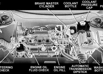
m 3.8L Engines . . . . . . . . . . . . . . . . . . . . . . . . . . 370
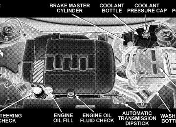
m 4.0L Engines . . . . . . . . . . . . . . . . . . . . . . . . . . 371
m Onboard Diagnostic System — OBD II . . . . . . . . 372
N Loose Fuel Filler Cap Message . . . . . . . . . . . . 373m Emissions Inspection And Maintenance
Programs
. . . . . . . . . . . . . . . . . . . . . . . . . . . . 373
m Replacement Parts . . . . . . . . . . . . . . . . . . . . . . 375
m Dealer Service . . . . . . . . . . . . . . . . . . . . . . . . . 375
m Maintenance Procedures . . . . . . . . . . . . . . . . . . 376N Engine Oil . . . . . . . . . . . . . . . . . . . . . . . . . . 376
N Engine Oil Filter . . . . . . . . . . . . . . . . . . . . . . 379
N Drive Belt . . . . . . . . . . . . . . . . . . . . . . . . . . . 379
N Spark Plugs . . . . . . . . . . . . . . . . . . . . . . . . . 379
N Engine Air Cleaner Filter . . . . . . . . . . . . . . . . 380
N Catalytic Converter . . . . . . . . . . . . . . . . . . . . 380
N Maintenance-Free Battery . . . . . . . . . . . . . . . . 382
N Air Conditioner Maintenance . . . . . . . . . . . . . 383
N Power Steering — Fluid Check . . . . . . . . . . . . 385368 MAINTAINING YOUR VEHICLE
N Front & Rear Suspension Ball Joints . . . . . . . . 385
N Steering Shaft Seal . . . . . . . . . . . . . . . . . . . . 385
N Steering Linkage . . . . . . . . . . . . . . . . . . . . . . 386
N Drive Shaft Universal Joints . . . . . . . . . . . . . . 386
N Body Lubrication . . . . . . . . . . . . . . . . . . . . . 386
N Windshield Wiper Blades . . . . . . . . . . . . . . . . 387
N Windshield And Rear Window Washers . . . . . 387
N Exhaust System . . . . . . . . . . . . . . . . . . . . . . 388
N Cooling System . . . . . . . . . . . . . . . . . . . . . . . 389
N Hoses And Vacuum/Vapor Harnesses . . . . . . . 394
N Brakes . . . . . . . . . . . . . . . . . . . . . . . . . . . . . 394
N Master Cylinder — Brake Fluid Level Check . . 396
N Fuel System Hoses . . . . . . . . . . . . . . . . . . . . 397N Automatic Transmission . . . . . . . . . . . . . . . . 398
N All Wheel Drive (AWD) — If Equipped . . . . . 400
N Front And Rear Wheel Bearings . . . . . . . . . . . 401
N Appearance Care And Protection FromCorrosion . . . . . . . . . . . . . . . . . . . . . . . . . . . 401
N Cleaning The Center Console Cup Holders . . . 406
m Fuses (Integrated Power Module) . . . . . . . . . . . 407
m Vehicle Storage . . . . . . . . . . . . . . . . . . . . . . . . 410
m Replacement Light Bulbs . . . . . . . . . . . . . . . . . 411
m Bulb Replacement . . . . . . . . . . . . . . . . . . . . . . 412
N Headlights . . . . . . . . . . . . . . . . . . . . . . . . . . 412
N High Intensity Discharge Headlights (HID) —If Equipped . . . . . . . . . . . . . . . . . . . . . . . . . 413
N Front Park/Turn Signal And Sidemarker
Lights . . . . . . . . . . . . . . . . . . . . . . . . . . . . . 413
. . . . . . . . . . . . . . . . . . . . . . 414N Front Fog Light N Rear Tail, Stop, Turn Signal, Side Marker And
Back-Up Lights . . . . . . . . . . . . . . . . . . . . . . . 415
. . . . . . . . . . . . . . . . . . . . . . . . 415N License Light
MAINTAINING YOUR VEHICLE 369
m Fluids And Capacities . . . . . . . . . . . . . . . . . . . 416
m Fluids, Lubricants And Genuine Parts . . . . . . . . 417
N Engine . . . . . . . . . . . . . . . . . . . . . . . . . . . . . 417
N Chassis . . . . . . . . . . . . . . . . . . . . . . . . . . . . 418370 MAINTAINING YOUR VEHICLE
3.8L ENGINES
Engine Compartment 3.8L Engines
4.0L ENGINES
MAINTAINING YOUR VEHICLE 371
Engine Compartment 4.0L Engine
372 MAINTAINING YOUR VEHICLE
ONBOARD DIAGNOSTIC SYSTEM — OBD II Your vehicle is equipped with a sophisticated onboard diagnostic system called OBD II. This system monitors the performance of the emissions, engine, and automatic transmission control systems. When these systems are operating properly, your vehicle will provide excellent performance and fuel economy, as well as engine emis- sions well within current government regulations. If any of these systems require service, the OBD II system will turn on the “Malfunction Indicator Light.” It will also store diagnostic codes and other information to assist your service technician in making repairs. Al- though your vehicle will usually be drivable and not need towing, see your dealer for service as soon as possible.
CAUTION!
† Prolonged driving with the “Malfunction Indica- tor Light” on could cause further damage to the emission control system. It could also affect fuel economy and driveability. The vehicle must be serviced before any emissions tests can be per- formed. † If the “Malfunction Indicator Light” is flashing while the engine is running, severe catalytic con- verter damage and power loss will soon occur. Immediate service is required.
Loose Fuel Filler Cap Message Should the “Loose Fuel Filler Cap” or “gASCAP” mes- sage appear, there may be a problem in the evaporative system. Before taking the vehicle into a qualified Dealer- ship Service center, check first to see if the fuel filler cap is possibly loose, improperly installed, or damaged. A loose fuel filler cap message will be displayed in the instrument cluster. Tighten the gas cap until a 9clicking9
sound is heard. This is an indication that the gas cap is properly tightened. Press the odometer reset button to turn the message off. If the problem persists, the message will appear the next time the vehicle is started. If the problem is detected twice in a row, the system will turn on the Malfunction Indicator Light (MIL). Resolving the problem will turn the MIL light off. Take your vehicle in to a qualified Dealership Service center.MAINTAINING YOUR VEHICLE 373
EMISSIONS INSPECTION AND MAINTENANCE PROGRAMS In some localities, it may be a legal requirement to pass an inspection of your vehicle’s emissions control system. Failure to pass could prevent vehicle registration.
For states, which have an I/M (Inspection and Maintenance) requirement, this check verifies the following: the MIL (Malfunction Indicator Light) is functioning and is not on when the engine is running, and that the OBD (On Board Diagnostic) system is ready for testing. Normally, the OBD system will be ready. The OBD system may not be ready if your vehicle was recently serviced, if you recently had a dead battery, or a battery replacement. If the OBD system should be determined not ready for the I/M test, your vehicle may fail the test.
374 MAINTAINING YOUR VEHICLE
Your vehicle has a simple ignition key actuated test, which you can use prior to going to the test station. To check if your vehicle’s OBD system is ready, you must do the following: 1. Insert your ignition key into the ignition switch. 2. Turn the ignition to the ON position, but do not crank or start the engine. 3. If you crank or start the engine, you will have to start this test over. 4. As soon as you turn your key to the ON position, you will see your MIL symbol come on as part of a normal bulb check. 5. Approximately 15 seconds later, one of two things will happen:
a. The MIL will flash for about 10 seconds and then return to being fully illuminated until you turn off the
ignition key or start the engine. This means that your vehicle’s OBD system is not ready and you should not proceed to the I/M station. b. The MIL will not flash at all and will remain fully illuminated until you turn off the ignition key or start the engine. This means that your vehicle’s OBD system is ready and you can proceed to the I/M station.
If your OBD system is not ready, you should see your authorized dealer or repair facility. If your vehicle was recently serviced or had a battery failure or replacement, you may need to do nothing more than drive your vehicle as you normally would in order for your OBD system to update. A recheck with the above test routine may then indicate that the system is now ready. Regardless of whether your vehicle’s OBD system is ready or not ready, if the MIL symbol is illuminated during normal vehicle operation, you should have your
vehicle serviced before going to the I/M station. The I/M station can fail your vehicle because the MIL symbol is on with the engine running.
NOTE: systems can result against you.
Intentional tampering with emissions control in civil penalties being assessed
MAINTAINING YOUR VEHICLE 375
REPLACEMENT PARTS Use of genuine Mopart parts for normal/scheduled maintenance and repairs is highly recommended to in- sure the designed performance. Damage or failures caused by the use of non-Mopart parts for maintenance and repairs will not be covered by the manufacturer’s warranty.
DEALER SERVICE Your dealer has the qualified service personnel, special tools, and equipment to perform all service operations in an expert manner. Service Manuals are available which include detailed service information for your vehicle. Refer to these manuals before attempting any procedure yourself.
WARNING!
You can be badly injured working on or around a motor vehicle. Only do service work for which you have the knowledge and the proper equipment. If you have any doubt about your ability to perform a service job, take your vehicle to a competent mechanic.