- Download PDF Manual
-
Release Handle 1 Location
2. Pull the release strap “2” located at the bottom of the seat to lift and tumble the seat forward.
Release Strap 2 Location
To relatch the seat, tilt the seat rearward and push down firmly to engage the rear attachments. Then lift the seatback release lever labeled “1” and pull the seatback up to return it to its full upright position.
126 UNDERSTANDING THE FEATURES OF YOUR VEHICLE
Third Row Seating — If Equipped The third row seats may be used with either or both seatbacks folded forward for additional storage space. To fold the seat, remove any objects from in front of or on the seat. Then pull handle located on the seatback and push it forward.
Seat Release Handle
WARNING!
Do not sit in the 3rd row seat with the second row seatbacks folded or with the second row seats folded and tumbled. In a collision, you could slide under the seat belt and be seriously or even fatally injured.
To raise the 3rd row seat, lift up on the seatback and push rearward until the seatback is latched. Move the seatback forward to be sure the seatback is fully latched.
CAUTION!
Be sure there is nothing in front of the 3rd row seat cushion before folding it down. Damage to the seat may occur.
UNDERSTANDING THE FEATURES OF YOUR VEHICLE 127
Load Floor — If Equipped For additional cargo space, the second and third row seatbacks may be folded forward and the load floor extended to cover the center console. To extend the load floor, follow these steps: 1. Move the second row seats to the full rear position. 2. Fold the second and third row seatbacks down.
WARNING!
† Not all head restraints in this vehicle are the same. Head restraints from one seating position should not be removed and installed in any other seating position. In a collision, serious injury or death may result if the proper head restraint is not installed on each seat. † The cargo area in the rear of the vehicle should not be used as a play area by children. They could be seriously injured in a collision. Children should be seated and using the proper restraint system. † It is extremely dangerous to ride in a cargo area, inside or outside of a vehicle. In a collision, people riding in these areas are more likely to be seriously injured or killed. † Do not allow people to ride in any area of your vehicle that is not equipped with seats and seat belts. † Be sure everyone in your vehicle is in a seat and
using a seat belt properly.
128 UNDERSTANDING THE FEATURES OF YOUR VEHICLE
3. Pull on the load floor strap and lift the panel from the driver’s second row seatback over the center console and onto the passenger second row seat.
Plastic Grocery Bag Retainer Retainer hooks which will hold plastic grocery bag handles are built into the seatbacks of all front seats. The floor supports the partial weight of the bagged goods.
Load Floor Panel
NOTE: Be sure to reattach the strap to secure the load floor panel when not in use.
Grocery Bag Holders
DRIVER MEMORY SEAT — IF EQUIPPED If your vehicle is equipped with memory systems, your remote keyless entry transmitter or memory seat buttons on the driver’s door panel can be used to recall the driver’s seat, outside mirrors, adjustable pedals (if equipped) and radio station presets to saved positions.
Driver Memory Switches
UNDERSTANDING THE FEATURES OF YOUR VEHICLE 129
The memory seat buttons located on the driver’s door will always recall stored settings. The remote keyless entry transmitter can be programmed to recall positions when the UNLOCK button is pressed. Refer to the following procedure on how to link a remote keyless entry transmitter to a position. NOTE: The vehicle must be in Park to recall memory positions. If a recall is attempted when the vehicle is not in Park, a message will be displayed in the Electronic Vehicle Information Center (EVIC). To recall memory positions press memory button number 1 if you are recalling the memory position for driver one or press memory button number 2 if you are recalling the memory position for driver two. A recall can be cancelled by pressing any of the memory buttons during a recall. When a recall is cancelled, the seat stops moving and a delay of approximately one second will occur before any other recalls can be selected.
130 UNDERSTANDING THE FEATURES OF YOUR VEHICLE
Your vehicle has been delivered with two remote keyless entry transmitters. One or both transmitters can be linked to either memory position. Up to eight remote keyless entry transmitters can be used with your vehicle. The memory seat system can also accommodate up to eight transmitters linked to either of the two stored seat positions or any combination of the two positions. To Program Memory Seat Buttons & RKE Transmitters, Follow These Steps: 1. Turn the ignition switch to the ON position. 2. Select Remote Linked to Memory from the EVIC and enter “Yes”. 3. Use the seat, mirror and adjustable pedal switches to adjust the seat, recliner, side view mirrors and adjustable pedals to the desired positions. 4. Set the radio station presets.
5. Turn the ignition switch to the OFF position and remove the key. 6. Press and release the SET (S) button located on the driver’s door. A light in the button will flash telling you that you are in the set memory mode. You have five seconds to complete the next step. 7. Within 5 seconds, press and release button 1 or 2 on the driver’s door. A chime will sound signaling you that the driver memory has been set. A message will also be displayed in the Electronic Vehicle Information Center (EVIC), indicating a position has been set. 8. Within 5 seconds, press and release the LOCK button on one of the Remote Keyless Entry Transmitters. A chime will sound signaling you that the transmitter has been successfully linked. A message will also be dis- played in the Electronic Vehicle Information Center (EVIC), indicating the transmitter has been linked.
Repeat the above steps for the second position using the other driver’s door numbered button and Remote Key- less Entry Transmitter. Each time the SET (S) button and a numbered button are pressed, you erase the old memory and store a new one. To Disable A Transmitter Link, Follow These Steps: 1. Turn the ignition switch to the ON position. 2. Select “Remote Linked To Memory” from the Elec- tronic Vehicle Information Center (EVIC), Customer Pro- grammable features and enter “YES.”. 3. Turn the ignition switch to the OFF position and remove the key. 4. Press and release the SET(S) button located on the driver’s door. A light in the button will flash telling you that you are in the set memory mode. You have five seconds to complete the next step.
UNDERSTANDING THE FEATURES OF YOUR VEHICLE 131
5. Within 5 seconds, press and release button 1 or 2 on the driver’s door. A chime will sound signaling you that the driver memory has been set. A message will also be displayed in the EVIC, indicating a position has been set. 6. Within 5 seconds, press and release the UNLOCK button on the remote keyless entry transmitters. A chime will sound signaling you that the transmitter link has been successfully disabled. A message will also be dis- played in the EVIC, indicating the transmitter has been disabled. To disable another transmitter from memory positions 1
or 2, repeat the above steps for each transmitter. NOTE: This function can be selected using the “Cus- tomer Programmable Features” in the EVIC section, otherwise see your authorized dealer for assistance.132 UNDERSTANDING THE FEATURES OF YOUR VEHICLE
Easy Exit Seat (Available with Memory Seat Only) This feature provides automatic driver’s seat positioning which will enhance driver mobility out of and into the vehicle. There are two possible Easy Exit and Easy Entry adjust- ments available: † The seat cushion will move rearward approximately 2.5 inches (60 mm) if the starting position of the seat is greater than or equal to 4.72 inches (120 mm) forward of the rear seat stop when the key is removed from the ignition switch. The seat will then move forward approximately 2.5 inches (60 mm) when the key is placed into the ignition and turned out of the LOCK position. † The seat shall move to the position located 1 1/8
inches (30 mm) forward of the rear stop if the starting position is between 2.5 inches to 4.72 inches (60 mm to 120 mm) forward of the rear stop when the key isremoved from the ignition switch. The seat will move forward to the memory/driving position when the key is placed into the ignition and turned out of the LOCK position.
The Easy Entry and Easy Exit feature will be automati- cally disabled if the seat is already positioned closer than 2.5 inches (60 mm) forward of the rear stop. At this position there is no benefit to the driver by moving the seat for Easy Exit or Easy Entry. Each stored memory setting will have an associated Easy Entry and Easy Exit position. NOTE: The Easy Exit Seat feature is not enabled when the vehicle is delivered from the factory. The Easy Exit Seat feature can be enabled or disabled through the customer programmable features in the Electronic Ve- hicle Information Center (EVIC), refer to “Easy Exit Seat?” under “Use Factory Settings”.
Tilt Mirrors in Reverse (Available with Memory Seat Only) — If Equipped This additional feature provides automatic outside mir- ror positioning which will aid the driver’s view of the ground rearward of the front doors. The outside mirrors will move slightly downward from the present position when the vehicle is shifted into the Reverse position. The outside mirrors will then return to the original position when the vehicle is shifted out of Reverse position. Each stored memory setting will have an associated Tilt Mir- rors in Reverse position. NOTE: The Tilt Mirrors in Reverse feature is not en- abled when delivered from the factory. The Tilt Mirrors in Reverse feature can be enabled or disabled through the customer programmable features in the Electronic Ve- hicle Information Center (EVIC), refer to “Tilt Mirrors in Reverse?” under “Use Factory Settings”.
UNDERSTANDING THE FEATURES OF YOUR VEHICLE 133
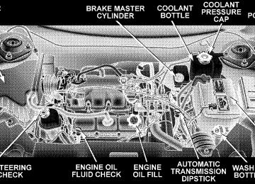
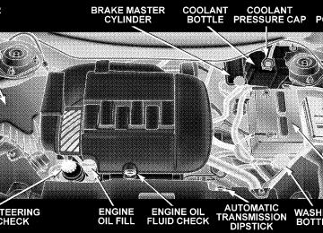
TO OPEN AND CLOSE THE HOOD To open the hood, two latches must be released. First pull the hood release lever located under the left side of the instrument panel.
Hood Release Lever
134 UNDERSTANDING THE FEATURES OF YOUR VEHICLE
Next, push to the left the safety catch located under the front edge of the hood, near the center.
Hood Safety Catch
Use the hood prop rod to secure the hood in the open position. To prevent possible damage, do not slam the hood to close it. Lower the hood until it is open approximately 15
cm (6 inches) and then drop it. This should secure both latches. Never drive your vehicle unless the hood is fully closed, with both latches engaged.
WARNING!
If the hood is not fully latched, it could fly up when the vehicle is moving and block your forward vision. You could have a collision. Be sure all hood latches are fully latched before driving.
LIGHTS
Overhead Console Map/Reading Lights These lights are mounted between the sun visors on the overhead console. Each light is turned ON by pressing the lens. Press the lens a second time to turn the light
OFF. The lights also turn on when a door is opened or the dimmer control is turned fully upward, past the second detent.
UNDERSTANDING THE FEATURES OF YOUR VEHICLE 135
NOTE: The lights will remain on until the switch is pressed a second time, so be sure they have been turned off before leaving the vehicle. Interior Lights The interior lights come on when a door is opened. The interior lights will automatically turn off in about 15
minutes if a door is left open or the dimmer control is left in the Dome light position. Turn the ignition switch ON to restore the interior light operation.Map/Reading Lights
136 UNDERSTANDING THE FEATURES OF YOUR VEHICLE
Multi-Function Lever The Multi-Function Lever controls the operation of the headlights, parking lights, turn signals, headlight beam selection, instrument panel light dimming, interior lights, the passing lights, and fog lights. The lever is located on the left side of the steering column.
Multi-Function Control Lever
Headlights, Parking Lights, Instrument Panel Lights Turn the end of the Multi-Function Lever to the first detent for parking light and instrument panel light operation. Turn to the second detent for headlight, park light and instrument panel light operation. To change the brightness of the instrument panel lights, rotate the center portion of the Multi-Function Lever up or down. Dimmer Control
With the parking lights or headlights on, rotating the dimmer control for the interior lights on the Multi-Function Lever upward will increase the bright- ness of the instrument panel lights.
Dome Light Position
Rotate the dimmer control completely upward to the second detent to turn on the interior lights. The interior lights will remain on when the dim- mer control is in this position.
UNDERSTANDING THE FEATURES OF YOUR VEHICLE 137
Parade Mode (Daytime Brightness Feature)
Rotate the dimmer control upward to the first detent. This feature brightens the odometer and radio display when the parking lights or headlights are on during daylight conditions.
Interior light Defeat (OFF)
Rotate the dimmer control to the ex- treme bottom “OFF” position. The in- terior lights will remain off when the doors are open.
Automatic Headlights This system automatically turns your headlights ON or OFF based on ambient light levels. To turn the system ON, turn the end of the Multi-Function Lever to the third detent position. When the system is ON, the Headlight Time Delay feature is also ON. This means your head- lights will stay ON for up to 90 seconds after you turn the ignition switch OFF. To turn the Automatic System OFF, turn the end of the Multi-Function Lever to the OFF position.
138 UNDERSTANDING THE FEATURES OF YOUR VEHICLE
NOTE: The engine must be running before the head- lights will come ON in the Automatic mode. Daytime Running Lights (Canada Only) The high beam headlights will come on as Daytime Running Lights whenever the ignition switch is on, the headlights are off, and the parking brake is off. The headlight switch must be used for normal night time driving. Lights-on Reminder If the headlights or parking lights are on after the ignition is turned OFF, a chime will sound to alert the driver when the driver’s door is opened. Headlight Time Delay This feature provides the safety of headlight illumination for up to 90 seconds, when leaving your vehicle in an unlighted area.
To activate the delay feature, turn off the ignition switch while the headlights are still on. Then turn off the headlights within 45 seconds. The 90 second delay inter- val begins when headlight switch is turned off. If the headlights or park lights are turned back on or the ignition switch is turned on, the delay will be cancelled. If the headlights are turned off before the ignition, they will turn off in the normal manner. NOTE: The lights must be turned off within 45 seconds of turning the ignition off to activate this feature Fog Lights — If Equipped
The front fog light switch is on the Multi-Function Lever. To activate the front fog lights, turn on the parking lights or the low beam headlights and pull
out the end of the Multi-Function Lever.
NOTE: The fog lights will only operate with the head- lights on low beam. Selecting high beam headlights will turn off the fog lights. Turn Signals Move the lever up or down to signal a right-hand or left-hand turn. The arrow on either side of the instrument cluster flashes to indicate the direction of the turn, and proper operation of the front and rear turn signal lights. If an indicator fails to light when the lever is moved, it would suggest that the switch or indicator lamp is defective. If a defective bulb or wiring circuit is detected for the turn signal system, the arrow indicators will flash at a faster rate. You can signal a lane change by moving the lever partially up or down.
UNDERSTANDING THE FEATURES OF YOUR VEHICLE 139
If a turn signal has been left on for at least a mile
NOTE: duration, a continuous chime will sound. Turn Signal Lane Change Auto-Mode Momentarily engage the multifunction control lever par- tially up or down to activate the lane change feature without holding the lever. The signal will flash 3 times, and automatically turn off. Highbeam/Lowbeam Select Switch Pull the Multi-Function Lever towards you to switch the headlights to HIGH beam. Pull the Lever a second time to switch the headlights to LOW beam. Passing Light You can signal another vehicle with your headlights by lightly pulling the Multi-Function Lever toward you. This will cause the headlights to turn on at high beam and remain on until the lever is released.
140 UNDERSTANDING THE FEATURES OF YOUR VEHICLE
WINDSHIELD WIPERS AND WASHERS
The wipers and washers are operated by a switch on the control lever. The lever is located on the right side of the steering column. Rotate the end
of the control lever to select the desired wiper speed.
Windshield Washers To use the front washer, pull the lever toward you and hold while spray is desired. If the lever is pulled while in the delay range, the wiper will operate for two wipe cycles after the lever is released, and then resume the intermittent interval previously selected. If the lever is pulled while in the OFF position, the wipers will operate for two wipe cycles, then turn OFF. Mist Feature Push down on the wiper lever to activate a single wipe to clear off road mist or spray from a passing vehicle. As long as the lever is held down, the wipers will continue to operate.
Windshield Wiper/Washer Control
Windshield Wiper Operation Rotate the end of the lever to the second detent for Low speed wiper operation, or to the third detent for High speed operation Intermittent Wiper System Use the intermittent wiper when weather conditions make a single wiping cycle, with a variable pause be- tween cycles, desirable. Rotate the end of the lever to the first detent position, then turn the end of the lever to select the desired delay interval. The delay can be regu- lated from a maximum of approximately 23 seconds between cycles, to a cycle every second. Rear Window Wiper/Washer The switch on the right side of the steering column also controls operation of the rear wiper/washer function.
UNDERSTANDING THE FEATURES OF YOUR VEHICLE 141
Windshield Wiper/Washer Control
Rotating the center of the switch up to the DEL (Delay) position or the ON position will activate the rear wiper. Push the lever forward to initiate the rear wash function in any of the three positions. The washer pump will
142 UNDERSTANDING THE FEATURES OF YOUR VEHICLE
continue to operate as long as the lever is pressed. Upon release, the rear wiper will cycle two times before return- ing to the set position. Adding Washer Fluid The fluid reservoir for the windshield washers and the rear window washer is shared. It is located in the front of the engine compartment on the driver’s side and should be checked for fluid level at regular intervals. Fill the reservoir with windshield washer solvent (not radiator antifreeze) and operate the system for a few seconds to flush out the residual water.
Washer Fluid Reservoir
The washer fluid reservoir will hold a full gallon of fluid when Low Washer Fluid illuminates in the Electronic Vehicle Information Center (EVIC).
TILT STEERING COLUMN To tilt the column, pull the lever, located behind the turn signal control, toward you and move the steering wheel up or down, as desired. Release the lever to lock the steering wheel firmly in place.
UNDERSTANDING THE FEATURES OF YOUR VEHICLE 143
WARNING!
Tilting the steering column while the vehicle is moving is dangerous. Without a stable steering col- umn, you could lose control of the vehicle and have an accident. Adjust the column only while the ve- hicle is stopped. Be sure it is locked before driving.
Tilt Steering Column Control
144 UNDERSTANDING THE FEATURES OF YOUR VEHICLE
ELECTRONIC SPEED CONTROL When engaged, this device takes over the accelerator operation at speeds greater than 30 mph (50 km/h). The speed control switches are located on the steering wheel.
To Activate: Push the “ON/OFF” button once and the CRUISE indi- cator located near the instrument cluster odometer will illuminate showing the electronic speed control system is on. To turn the system OFF, push the “ON/OFF” button again and the system and indicator will turn off.
WARNING!
Leaving the Electronic Speed Control system on when not in use is dangerous. You could accidently set the system or cause it to go faster than you want. You could lose control and have an accident. Always leave the system OFF when you aren’t using it.
SPEED CONTROL BUTTONS
To Set a Desired Speed:
When the vehicle has reached the desired speed, press and release the “SET” button. Release the accelerator and the vehicle will operate at the selected speed. The CRUISE SET indicator located near the instrument clus- ter odometer will illuminate showing the electronic speed control is set. NOTE: While in the AutoStick mode, Speed Control will only function in third or fourth gear (4 speed AutoStick) and fifth or sixth gear (6 speed AutoStick). To Deactivate: A soft tap on the brake pedal, pushing the “CANCEL” button or normal braking while slowing the vehicle will deactivate the speed control without erasing the memory. Pushing the “ON/OFF” button to the OFF position or turning off the ignition erases the speed memory.
UNDERSTANDING THE FEATURES OF YOUR VEHICLE 145
To Resume Speed: To resume a previously set speed, push and release the “ACCEL/RESUME” button. Resume can be used at any speed above 25 mph (40 km/h). To Vary the Speed Setting: When the speed control is set, speed can be increased by pressing and holding the “ACCEL/RESUME” button. When the button is released, a new set speed will be established. Tapping the “ACCEL/RESUME” button once will result in a 2 mph (3 km/h) speed increase. Each time the button is tapped, speed increases so that tapping the button three times will increase speed by 6 mph (10 km/h), etc. To decrease speed while speed control is set, press and hold the “COAST” button. Release the button when the desired speed is reached, and the new speed will be set.
146 UNDERSTANDING THE FEATURES OF YOUR VEHICLE
Tapping the “COAST” button once will result in a 1 mph (2 km/h) speed decrease. Each time the button is tapped, speed decreases. To Accelerate For Passing: Depress the accelerator as you would normally. When the pedal is released, the vehicle will return to the set speed. NOTE: The speed control system maintains speed up and down hills. A slight speed change on moderate hills is normal. Four speed automatic transmissions will experience a downshift to 3rd gear (5th gear on 6 speed AutoStick) while climbing uphill or descending downhill. This downshift to 3rd (5th gear on 6 speed AutoStick) gear is necessary to maintain vehicle set speed. On steep hills a greater speed loss or gain may occur so it may be preferable to drive without speed control.
WARNING!
Speed Control can be dangerous where the system can’t maintain a constant speed. Your vehicle could go too fast for the conditions, and you could lose control. An accident could be the result. Don’t use Speed Control in heavy traffic or on roads that are winding, icy, snow-covered, or slippery.
GARAGE DOOR OPENER — IF EQUIPPED HomeLinkt replaces up to three remote controls (hand held transmitters) that operate devices such as garage door openers, motorized gates, lighting, or home security systems. The HomeLinkt unit operates off of your vehi- cle’s battery. NOTE: HomeLinkt is disabled when the Vehicle Theft Alarm is active.
WARNING!
WARNING!
UNDERSTANDING THE FEATURES OF YOUR VEHICLE 147
Your motorized door or gate will open and close while you are training the Universal Transceiver. Do not train the transceiver if people or pets are in the path of the door or gate. Only use this transceiver with a garage door opener that has a “stop and reverse” feature as required by federal safety stan- dards. This includes most garage door opener models manufactured after 1982. Do not use a garage door opener without these safety features. Call toll-free 1–800–355–3515
at www.HomeLink.com for safety information or assistance.Internet
the
on
or,
Vehicle exhaust contains carbon monoxide, a danger- ous gas. Do not run your vehicle in the garage while training the transceiver. Exhaust gas can cause seri- ous injury or death.
Programming HomeLinkT
Before You Begin If you have not trained any of the HomeLinkt buttons, erase all channels before you begin training. To do this, press and hold the two outside buttons for 20
seconds until the red HomeLinkt indicator begins to flash, or the EVIC message changes from “CLEARING CHANNELS” to “CHANNELS CLEARED.” It is recommended that a new battery be placed in the hand-held transmitter of the device being programmed148 UNDERSTANDING THE FEATURES OF YOUR VEHICLE
to HomeLinkt for more efficient training and accurate transmission of the radio-frequency signal. Your vehicle should be parked outside of the garage while training. 1. Turn the ignition switch to the ON/RUN position. 2. Place the hand-held transmitter 1–3 inches (3–8 cm) from the HomeLinkt buttons while keeping the indicator in view. For optimal training, point the battery end of the hand- held transmitter away from the HomeLinkt. 3. Simultaneously press and hold both the chosen HomeLinkt button and the hand-held transmitter button until the until the red HomeLinkt indicator changes from a slow to a rapid flash rate or the EVIC display changes from “CHANNEL # TRAINING” to “CHANNEL # TRAINED.”
Then release both the HomeLinkt and hand-held trans- mitter buttons. If the EVIC display states “DID NOT TRAIN” repeat Step 3. If the signal is too weak, replace the battery in the original hand-held transmitter. It may take up to 30 seconds, or longer in rare cases. The garage door may open & close while you train. NOTE: Some gate operators and garage door openers may require you to replace Step #3 with procedures noted in the “Gate Operator/Canadian Programming” section. 4. Press and hold the newly-trained HomeLinkt button. If the channel has been trained, the EVIC display will now state “CHANNEL # TRANSMIT.” If the EVIC display still states “CHANNEL # TRAIN- ING” repeat Step 3.
If the red HomeLinkt indicator blinks rapidly for two seconds and then remains constant, continue with the next section: “Programing A Rolling Code.” NOTE: After training a HomeLinkt channel, if the garage door does not operate with HomeLinkt and the garage door opener was manufactured after 1995, the garage door opener may have a rolling code. If so, proceed to the heading “Programming A Rolling Code System.” 5. PROGRAMMING A ROLLING CODE SYSTEM At the garage door opener motor (in the garage), locate the “learn” or “training” button. This can usually be found where the hanging antenna wire is attached to the garage door opener motor (IT IS NOT THE BUTTON NORMALLY USED TO OPEN AND CLOSE THE DOOR).
UNDERSTANDING THE FEATURES OF YOUR VEHICLE 149
1 — Garage Door Opener 2 — Training Button 6. Firmly press and release the “learn” or “training” button. The name and color of the button may vary by manufacturer. NOTE: There are 30 seconds in which to initiate the next step after the “Learn” button has been pressed.
150 UNDERSTANDING THE FEATURES OF YOUR VEHICLE
7. Return to the vehicle and press the programmed HomeLinkt button twice (holding the button for 2 sec- onds each time). If the device is plugged in and activates, programming is complete. If the device does not activate, press the button a third time (for 2 seconds) to complete the training. If you are have any problems, or require assis- NOTE: tance, please call toll-free 1–800–355–3515 or, on the Internet at www.HomeLink.com for information or assis- tance. To program the remaining two HomeLinkt buttons, repeat each step for each remaining button. DO NOT ERASE THE CHANNELS.
Canadian Programming/Gate Programming Canadian radio-frequency laws require transmitter sig- nals to 9time-out9 (or quit) after several seconds of transmission which may not be long enough for HomeLinkt to pick up the signal during programming. Similar to this Canadian law, some U.S. gate operators are designed to 9time-out9 in the same manner. It may be helpful to unplug the device during the cycling process to prevent possible overheating of the garage door or gate motor. If you are having difficulties programming a garage door opener or a gate operator, replace “Programming HomeLink” Step 3 with the following: 3. Continue to press and hold the HomeLinkt button while you press and release - every two seconds (“cycle”) your hand-held transmitter until HomeLinkt has successfully accepted the frequency signal. The red HomeLinkt indicator will change from a slow to rapid
flash, and the EVIC display in the cluster will change from “CHANNEL # TRAINING” to “CHANNEL # TRAINED.” If you unplugged the device for training, plug it back in at this time. Then proceed with the remaining steps. Using HomeLinkT To operate, simply press and release the programmed HomeLinkt button. Activation will now occur for the trained device (i.e. garage door opener, gate operator, security system, entry door lock, home/office lighting, etc.). The hand-held transmitter of the device may also be used at any time.
UNDERSTANDING THE FEATURES OF YOUR VEHICLE 151
that has been previously
Reprogramming a Single HomeLinkT Buttons To re-program a channel trained, follow these steps: 1. Turn the ignition switch to the ON/RUN position. 2. Press and hold the desired HomeLinkt button for 20
seconds until the red indicator starts to flash, or the EVIC display states “CHANNEL # TRAINING.”DO NOT RELEASE THE BUTTON. 3. WITHOUT RELEASING THE BUTTON, proceed with PROGRAMMING HOMELINK Step #2 and fol- low all remaining steps. Security It is advised to erase all channels before you sell or turn in your vehicle.152 UNDERSTANDING THE FEATURES OF YOUR VEHICLE
To do this, press and hold the two outside buttons for 20
seconds until the EVIC message states “CHANNELS CLEARED.” Note that all channels will be erased. Indi- vidual channels cannot be erased. The HomeLinkt Universal Transceiver is disabled when the Vehicle Theft Alarm is active. Troubleshooting Tips If you are having trouble programming HomeLinkt, here are some of the most common solutions: † Replace the battery in the original transmitter. † Press the Learn Button on the Garage Door Opener to † Did you unplug the device for training, and remembercomplete the training for Rolling Code.
to plug it back in?
If you are have any problems, or require assistance, please call toll-free 1–800–355–3515 or, on the Internet at www.HomeLink.com for information or assistance. General Information This device complies with FCC rules part 15 and Industry Canada RSS-210. Operation is subject to the following two conditions: 1. This device may not cause harmful interference 2. This device must accept any interference that may be received including interference that may cause undesired operation NOTE: The transmitter has been tested and it complies with FCC and IC rules. Changes or modifications not expressly approved by the party responsible for compli- ance could void the user’s authority to operate the device.
The term “IC” before the certification/registration num- ber only signifies that Industry Canada technical specifi- cations were met.
ANTI-LOCK BRAKE SYSTEM (ABS) ABS aids the driver in maintaining vehicle control under adverse braking conditions. The system controls hydrau- lic brake pressure to prevent wheel lockup and help avoid skidding on slippery surfaces during braking. NOTE: ABS improves steering control of the vehicle during hard braking maneuvers.
UNDERSTANDING THE FEATURES OF YOUR VEHICLE 153
WARNING!
† ABS cannot prevent the natural laws of physics from acting on the vehicle, nor can it increase braking or steering efficiency beyond that af- forded by the condition of the vehicle brakes and tires or the traction afforded. † ABS cannot prevent accidents, including those resulting from excessive speed in turns, following another vehicle too closely, or hydroplaning. Only a safe, attentive, and skillful driver can prevent accidents. † The capabilities of an ABS equipped vehicle must never be exploited in a reckless or dangerous manner which could jeopardize the user’s safety or the safety of others.
154 UNDERSTANDING THE FEATURES OF YOUR VEHICLE
ELECTRONIC BRAKE CONTROL SYSTEM - ABS/TCS/BAS/ESP Your vehicle is equipped with the advanced electronic brake control system that includes Anti-Lock Brake Sys- tem (ABS), Traction Control System (TCS) Brake Assist System (BAS), and Electronic Stability Program (ESP). All four systems work together to enhance vehicle stability and control in various driving conditions, and are com- monly referred to as ESP. Traction Control System (TCS) This system monitors the amount of wheel spin of each of the driven wheels. If wheel spin is detected, brake pressure is applied to the slipping wheel(s) and engine power is reduced to provide enhanced acceleration and stability. A feature of the TCS system functions similar to a limited slip differential and controls the wheel spin across a driven axle. If one wheel on a driven axle is spinning faster than the other, the system will apply the
brake of the spinning wheel. This will allow more engine torque to be applied to the wheel that is not spinning. Brake Assist System (BAS) The BAS is designed to optimize the vehicle’s braking capability during emergency braking maneuvers. The system detects an emergency braking situation by sens- ing the rate and amount of brake application and then applies optimum pressure to the brakes. This can help reduce braking distances. The BAS complements the anti-lock brake system (ABS). Applying the brakes very quickly results in the best BAS assistance. To receive the benefit of the system, you must apply continuous brak- ing pressure during the stopping sequence. Do not reduce brake pedal pressure unless braking is no longer desired. Once the brake pedal is released, the BAS is deactivated.
WARNING!
† BAS cannot prevent the natural laws of physics from acting on the vehicle, nor can it increase braking efficiency beyond that afforded by the condition of the vehicle brakes and tires or the traction afforded.
† The BAS cannot prevent accidents,
including those resulting from excessive speed in turns, following another vehicle too closely, or hydro- planing. Only a safe, attentive, and skillful driver can prevent accidents. † The capabilities of a BAS-equipped vehicle must never be exploited in a reckless or dangerous manner which could jeopardize the user’s safety or the safety of others.
UNDERSTANDING THE FEATURES OF YOUR VEHICLE 155
ESP (Electronic Stability Program)
This system enhances directional control and stability of the vehicle under various driving conditions. ESP cor- rects for over/under steering of the vehicle by applying the brake of the appropriate wheel to assist in counter- acting the over/under steer condition. Engine power may also be reduced to help the vehicle maintain the desired path. ESP uses sensors in the vehicle to determine the vehicle path intended by the driver and compares it to the actual path of the vehicle. When the actual path does not match the intended path, ESP applies the brake of the appropriate wheel to assist in counteracting the oversteer or understeer condition. † Oversteer - when the vehicle is turning more than † Understeer - when the vehicle is turning less than
appropriate for the steering wheel position.
appropriate for the steering wheel position.
156 UNDERSTANDING THE FEATURES OF YOUR VEHICLE
ESP/TCS Indicator Light The “ESP/TCS Indicator Light” located in the instrument cluster, starts to flash as soon as the tires lose traction and the ESP system becomes active. The “ESP/TCS Indicator Light” also flashes when TCS is active. If the “ESP/TCS Indicator Light” begins to flash during acceleration, ease up on the accelerator and apply as little throttle as possible. Be sure to adapt your speed and driving to the prevailing road conditions.
WARNING!
† Electronic Stability Program (ESP) cannot prevent the natural laws of physics from acting on the vehicle, nor can it increase the traction afforded by prevailing road conditions. † ESP cannot prevent accidents, including those resulting from excessive speed in turns, driving on very slippery surfaces, or hydroplaning. Only a safe, attentive, and skillful driver can prevent accidents. † The capabilities of an ESP-equipped vehicle must never be exploited in a reckless or dangerous manner which could jeopardize the user’s safety or the safety of others.
ESP Operating Modes The ESP system has 2 available operating modes. ESP ON This is the normal operating mode for ESP. Whenever the vehicle is started the ESP system will be in this mode. This mode should be used for most driving situations. ESP should only be turned to “Partial ESP” for specific reasons as noted below.
UNDERSTANDING THE FEATURES OF YOUR VEHICLE 157
Traction Control Switch
PARTIAL ESP This mode is entered by momentarily depressing the “ESP OFF” button. When in “Partial ESP” mode, the TCS portion of ESP has been disabled, the thresholds for ESP activation are
158 UNDERSTANDING THE FEATURES OF YOUR VEHICLE
raised, and the “ESP/TCS Indicator Light” will be illu- minated. This mode is intended to be used for a more spirited driving experience, or if the vehicle is in deep snow, sand, or gravel conditions and more wheel spin that ESP would normally allow is required.
To turn ESP on again, momentarily depress the “ESP OFF” button.
WARNING!
In the Partial ESP mode, the engine torque reduction and stability features are desensitized. Therefore, the enhanced vehicle stability offered by ESP is unavailable.
NOTE: To improve the vehicle’s traction when driving with snow chains, or starting off in deep snow, sand or gravel, it may be desirable to switch to the “Partial ESP” mode by pressing the “ESP OFF” button. Once the
situation requiring ESP to be switched to the “Partial ESP” mode is overcome, turn ESP back on by momen- tarily depressing the “ESP OFF” button. This may be done while the vehicle is in motion. ESP/BAS Warning Light and ESP/TCS Indicator Light The malfunction indicator for the ESP is combined with the BAS indicator. The yellow “ESP/BAS Warning Lamp” and the yellow “ESP/TCS Indicator Light” in the instrument cluster both come on when the ignition switch is turned to the “ON” position. They should both go out with the engine running. If the “ESP/BAS Warn- ing Lamp” comes on continuously with the engine running, a malfunction has been detected in either the ESP or BAS system, or both. If this light remains on after several ignition cycles, and the vehicle has been driven several miles at speeds greater than 30 mph (48 km/h), see your authorized dealer as soon as possible to have the problem diagnosed and corrected.
NOTE: † The “ESP Indicator Light” and the “ESP/BAS Warning Light” come on momentarily each time the ignition switch is turned ON. † Each time the ignition is turned ON, the ESP System † The ESP Control System will make buzzing or clicking sounds when it is active. This is normal; the sounds will stop when ESP becomes inactive following the maneuver that caused the ESP activation.
will be ON even if it was turned off previously.
ADJUSTABLE PEDALS — IF EQUIPPED This feature allows both the brake and accelerator pedals to move toward or away from the driver to provide improved position with the steering wheel. The adjust- able pedal system is designed to allow a greater range of driver comfort for steering wheel tilt and seat position. The switch is located on the drivers door trim panel next to the power seat switches.
UNDERSTANDING THE FEATURES OF YOUR VEHICLE 159
ADJUSTABLE PEDAL SWITCH
Press the switch forward to move the pedals forward (toward the front of the vehicle). Press the switch rearward to move the pedals rearward (toward the driver). † The pedals can be adjusted with the ignition OFF.
160 UNDERSTANDING THE FEATURES OF YOUR VEHICLE
† The pedals can be adjusted while driving. † The pedals cannot be adjusted when the vehicle is in R (Reverse) or when the Speed Control is ON. A message will be displayed in the Electronic Vehicle Information Center (EVIC) if the pedals are attempted to be ad- justed when the system is locked out (“Adjustable Pedal Disabled — Cruise Control Engaged” or “Ad- justable Pedal Disabled — Vehicle In Reverse”).
If your vehicle is equipped with memory seat NOTE: feature, your remote keyless entry transmitter or memory seat buttons on the driver’s door panel can be used to recall the adjustable pedals to saved positions.
CAUTION!
Do not place any article under the adjustable pedals or impede its ability to move as it may cause damage to the pedal controls. Pedal travel may become lim- ited if movement is stopped by an obstruction in the adjustable pedal’s path.
REAR PARK SENSE SYSTEM — IF EQUIPPED The Rear Park Assist System provides visual and audible indications of the distance between the rear fascia and the detected obstacle when backing up. When backing up the driver should also use the inside rearview and outside mirrors. The Rear Park Assist System will remember the last system state (enabled or disabled) from the last ignition cycle when the ignition is changed to the RUN/ON position.
The Rear Park Assist System can be active only when the transaxle shift lever is in R (Reverse). If the Rear Park Assist System is enabled at this shift position, the system will be active until the vehicle speed is increased to approximately 11 mph (18 km/h) or above. The system will be active again if the vehicle speed is decreased to speeds less than approximately 10 mph (16 km/h). Rear Park Assist Sensors The four Rear Park Assist Sensors, located in the rear fascia, monitor the area behind the vehicle that is within the sensors’ field of view. The monitored area seems oval in shape. The sensors can detect obstacles from approxi- mately 11.8 inches (30 cm) up to 59 inches (150 cm) from the rear fascia in the horizontal direction, depending on the location and orientation of the obstacle and the type of obstacle.
UNDERSTANDING THE FEATURES OF YOUR VEHICLE 161
Rear Park Assist LEDs
162 UNDERSTANDING THE FEATURES OF YOUR VEHICLE
Rear Park Assist Warning Display The Rear Park Assist Warning Display, located in the headliner near the liftgate glass, provides both visual and audible warnings to indicate the distance between the rear fascia and the detected obstacle. When the ignition is changed to the RUN/ON position, the warning display will turn ON all of its LEDs for about 1 second. Each side of the warning display has 6
yellow and 2 red LEDs. The vehicle is close to the obstacle when the red LED is ON.The driver can view the LEDs either through the rear view mirror or by looking at the display above the rear window. The system dimly illuminates the two outer most yellow LEDs when it is ON and detecting no obstacles. The following chart shows the warning display operation when the system is detecting an obstacle:
WARNING DISPLAY DISTANCES
DISPLAY LED
OBSTACLE DISTANCE FROM:
LED COLOR
AUDIBLE SIGNAL
UNDERSTANDING THE FEATURES OF YOUR VEHICLE 163
1st LED 2nd LED 3rd LED 4th LED 5th LED 6th LED 7th LED 8th LED
REAR CORNERS
31.5 in. (80 cm) 25.5 in. (65 cm) 20 in. (50 cm) 16 in. (40 cm) 6 in. (15 cm)
REAR CENTER 78.7 in. (200 cm) 51.2 in. (130 cm) 45.3 in. (115 cm) 39.3 in. (100 cm) 33.5 in. (85 cm) 27.6 in. (70 cm)
19.7 in. (50 cm) Red
11.8 in. (30 cm)
NOTE: The Rear Park Sense System will MUTE the radio, if on, when the audible warning is activated.
Yellow Yellow Yellow Yellow Yellow Yellow Red Red
Yes, half second
None None None None None
Yes, intermittent Yes, continuous
164 UNDERSTANDING THE FEATURES OF YOUR VEHICLE
WARNING!
† Drivers must be careful when backing up even when using the Rear Park Sense System. Always check carefully behind your vehicle, and be sure to check for pedestrians, animals, other vehicles, obstructions, or blind spots before backing up. You are respon- sible for the safety of your surroundings and must continue to pay attention while backing up. Failure to do so can result in serious injury or death. † Before using the Rear Park Sense System, it is strongly recommended that the ball mount and hitch ball assembly be disconnected from the vehicle when the vehicle is not used for towing. Failure to do so can result in injury or damage to vehicles or obstacles because the hitch ball will be much closer to the obstacle than the rear fascia when the warning display turns the red LEDs ON. Also, the sensors could detect the ball mount and hitch ball assembly, depending on its size and shape, giving a false indication that an obstacle is behind the vehicle.
CAUTION!
† To avoid vehicle damage the Rear Park Sense System should only be used as a parking aid and is unable to recognize every obstacle, including small objects. Parking curbs might be temporarily detected or not detected at all. Obstacles located above or below the sensors will not be detected when they are in close proximity to the rear of the vehicle. † To avoid vehicle damage the vehicle must be driven slowly when using the Rear Park Sense System to be able to stop in time when an obstacle is detected. It is recommended that the driver look over his/her shoulder when using the Rear Park Sense System.
NOTE: † Ensure that the rear bumper is free of dirt and debris † Jackhammers, large trucks, and other vibrations could
to keep the system operating properly.
affect the performance of the system.
If “Service Park Sense System” appears in the Electronic Vehicle Information Center (EVIC) after making sure the rear bumper is clean please see your authorized dealer. Enable/Disable the Rear Park Assist System — If Equipped The Rear Park Assist System can be enabled and disabled with a switch located on the switch bank of the instru- ment panel. When the switch is pressed to disable the system, the instrument cluster will display the 9PARK ASSIST DISABLED9 message. Refer to “Electronic Vehicle Information Center (EVIC)” in Section 4 of this manual. When the shift lever is changed to R (Reverse) and the
UNDERSTANDING THE FEATURES OF YOUR VEHICLE 165
system is disabled, the instrument cluster will actuate a single chime, once per ignition cycle, and it will display the message. The Rear Park Assist Switch LED will be ON when the Rear Park Assist System is disabled or defective. The Rear Park Assist Switch LED will be OFF when the system is enabled. The system can be turned on or off through the Electronic Vehicle Information Center (EVIC), if equipped. For details, refer to “Personal Settings (Customer Program- mable Features)” under “Electronic Vehicle Information enter (EVIC)” in Section 4 of this manual. Service the Rear Park Assist System When the Rear Park Assist System is defective, the instrument cluster will actuate a single chime, once per ignition cycle, and it will display the (SERVICE PARK ASSIST SYSTEM( message. Refer to “Electronic Vehicle Information Center (EVIC)” in Section 4 of this manual.
166 UNDERSTANDING THE FEATURES OF YOUR VEHICLE
If (SERVICE PARK ASSIST SYSTEM( appears in the Electronic Vehicle Information Center (EVIC) after mak- ing sure the rear bumper is clean please see your autho- rized dealer. Cleaning the Rear Park Assist System Clean the Rear Park Assist Sensors with water, car wash soap and a soft cloth. Do not use rough or hard cloths. Do not scratch or poke the sensors, otherwise, you could damage the sensors.
REAR CAMERA — IF EQUIPPED Your vehicle may be equipped with a Rear Camera system that allows you to see an on-screen image (located in the center of the instrument cluster) of the rear of your vehicle whenever it is put into R (Reverse). The camera is located in the light bar over the rear license plate.
NOTE: Refer to “Setting Display Properties” under “System Settings” in the Navigation User’s Manual for instructions regarding navigation screen brightness ad- justments. Use the following steps to access the Rear Backup Cam- era feature: 1. Start the engine. 2. Place shift lever in R (Reverse). 3. Wait one to two seconds, and the camera view will display on the instrument cluster. NOTE: The camera view will display only while the vehicle is in R (Reverse). 4. Perform a visual check of the rear area. NOTE: CHECK ENTIRE SURROUNDINGS before backing up.
5. Backup as necessary. 6. Place the sift lever in P (Park) or D (Drive) to exit the Rear Backup Camera system.
WARNING!
Drivers must be careful when backing up even when using the Rear Camera System. Always check care- fully behind your vehicle, and be sure to check for pedestrians, animals, other vehicles, obstructions, or blind spots before backing up. You are responsible for the safety of your surroundings and must con- tinue to pay attention while backing up. Failure to do so can result in serious injury or death.
UNDERSTANDING THE FEATURES OF YOUR VEHICLE 167
CAUTION!
† To avoid vehicle damage the Rear Camera System should only be used as a parking aid and is unable to view every obstacle, or object in your drive path. † To avoid vehicle damage the vehicle must be driven slowly when using the Rear Camera Sys- tem to be able to stop in time when an obstacle is seen. It is recommended that the driver look fre- quently over his/her shoulder when using the Rear Camera System.
If snow, ice, mud, or anything else builds up on NOTE: the camera lens, clean the lens, rinse with water, and dry with a soft cloth. Do not cover the lens.
168 UNDERSTANDING THE FEATURES OF YOUR VEHICLE
OVERHEAD CONSOLE — IF EQUIPPED The overhead console can contain courtesy/reading lights, an optional universal garage door opener (HomeLinkt), storage for sunglasses, optional power sunroof switches and an optional power liftgate switch.
Overhead Console
Courtesy/Reading Lights
At the forward end of the console are two courtesy/ reading lights. Press the lens to turn these lights on. Press a second time to turn the lights off. The lights also turn on when a front door, a rear door or the liftgate is opened. The lights will also turn on when the unlock button on the remote keyless entry transmitter is pressed. Sunglasses Storage At the rear of the overhead console, a compartment is provided for the storage of a pair of sunglasses. Press the door latch to open the compartment. The door will slowly rotate to an open position.
POWER SUNROOF — IF EQUIPPED The power sunroof buttons are located between the sun visors on the overhead console.
Power Sunroof buttons
UNDERSTANDING THE FEATURES OF YOUR VEHICLE 169
Press and hold the “OPEN” button rearward to fully open the sunroof. The sunroof can be stopped at any position between closed and full open. Momentarily pressing the “OPEN” button rearward will activate the Express Open Feature, causing the sunroof to open automatically. Press and hold the “VENT” button to open the vent. The sunroof can be stopped at any position between closed and full vent. To close the sunroof from the vent position, press and hold the “CLOSE” button forward. Releasing the button will stop the movement of the sunroof and the sunroof will remain in the partial vent position until the button is pushed forward again. NOTE: The power sunroof buttons remain active for up to 45 seconds after the ignition button has been turned off. Opening either front door will cancel this feature.
170 UNDERSTANDING THE FEATURES OF YOUR VEHICLE
Express Open Feature The sunroof is equipped with an intermediate stop or comfort stop position. This feature is designed to elimi- nate wind buffeting at vehicle speeds between 20-40 mph (32-64 km/h). To operate this feature, momentarily press the “OPEN” button rearward to activate the Express Open Feature and the glass will automatically stop at the comfort stop position. Pressing the button rearward again will fully open the sunroof. During the Express Open operation, any movement of the button will stop the sunroof and it will remain in a partial open position. Again, momentarily pressing the button rearward will activate the Express Open Feature.
To close the sunroof, press and hold the “CLOSE” button forward. Again, any release of the button will stop the movement and the sunroof will remain in a partial open condition until the button is pushed forward again. The sunshade can be opened manually. It will also open as the sunroof opens. The sunshade cannot be closed if the sunroof is open.
WARNING!
† NEVER leave children alone in a vehicle. Occu- pants, particularly unattended children, can be- come entrapped by the power sunroof while oper- ating the power sunroof switch. Such entrapment may result in serious injury or death. Don’t leave the keys in the ignition. A child could operate power windows, other controls, or move the ve- hicle † In an accident, there is a greater risk of being thrown from a vehicle with an open sunroof. You could also be seriously injured or killed. Always fasten your seat belt properly and make sure all passengers are properly secured too. † Do not allow small children to operate the sunroof. Never allow fingers or other body parts, or any object to project through the sunroof opening. Injury may result.
UNDERSTANDING THE FEATURES OF YOUR VEHICLE 171
Wind Buffeting Wind buffeting can be described as the perception of pressure on the ears or a helicopter type sound in the ears. Your vehicle may exhibit wind buffeting with the windows down, or the sunroof (if equipped) in certain open or partially open positions. This is a normal occur- rence and can be minimized. If the buffeting occurs with the rear windows open, open the front and rear windows together to minimize the buffeting. If the buffeting occurs with the sunroof open, adjust the sunroof opening to minimize the buffeting or open any window. Sunroof Comfort Position — If Equipped If equipped, some model sunroofs will stop at a prede- termined comfort position — not allowing the sunroof to open to the full retracted glass position. The comfort position stops the sunroof glass at approximately 3/4
open position. This will allow for minimal wind buffet- ing.172 UNDERSTANDING THE FEATURES OF YOUR VEHICLE
Sunroof Maintenance Use only a non-abrasive cleaner and a soft cloth to clean the glass panel.
ELECTRICAL POWER OUTLETS There are two 12 volt power outlets located on the instrument panel below the radio. The driver’s side outlet is controlled by the ignition switch and the passenger side outlet is connected directly to the battery. The driver’s side outlet will also operate a conventional cigar lighter unit (if equipped with an optional Smoker’s Package).
Front Power Outlets
A third outlet is located on the back of the front center console near the floor, and is also controlled by the ignition switch. A fourth outlet is located on the driver’s side, in the rear cargo area and is also controlled by the ignition switch.
The outlets include tethered caps labeled with a key or battery symbol indicating the power source. The passen- ger side instrument panel and center console outlets are powered directly from the battery, items plugged into these outlets may discharge the battery and/or prevent engine starting. The passenger side and center console outlets are pro- tected by an automatic reset circuit breaker. The auto- matic circuit breaker restores power when the overload is removed. If desired, the fourth power outlet in the rear NOTE: cargo area can be converted by your authorized dealer to provide power with the ignition switch in the OFF position.
UNDERSTANDING THE FEATURES OF YOUR VEHICLE 173
Electrical Outlet Use With Engine Off
CAUTION!
† Many accessories that can be plugged in draw power from the vehicle’s battery, even when not in use (i.e. cellular phones, etc.). Eventually, if plugged in long enough, the vehicle’s battery will discharge suffi- ciently to degrade battery life and/or prevent engine starting. † Accessories that draw higher power (i.e. coolers, vacuum cleaners, lights, etc.), will degrade the battery even more quickly. Only use these intermittently and with greater caution. † After the use of high power draw accessories, or long periods of the vehicle not being started (with accesso- ries still plugged in), the vehicle must be driven a sufficient length of time to allow the alternator to recharge the vehicle’s battery. † Power outlets are designed for accessory plugs only. Do not hang any type of accessory or accessory bracket from the plug. Improper use of the power outlet can cause damage.
174 UNDERSTANDING THE FEATURES OF YOUR VEHICLE
CUPHOLDERS
Front Seat Cupholders The cupholders are located in the forward edge of the center console. Push down on the forward edge of the console to release the cupholders. Press the cover up when the cupholders are no longer needed.
Second Row Seat Cupholders On vehicles equipped with five passenger seating the second row seat cupholders are located in middle of the seatback armrest. Pull down on the armrest to access the cupholders. Push the armrest up when the cupholders are no longer needed.
Six Passenger Seating Cupholders
Five Passenger Seating Cupholders
On vehicles equipped with six passenger seating the second row seat cupholders are located in the forward edge of the center console located between the second row seats. Push down on the forward edge of the console to release the cupholders. Press the cover up when the cupholders are no longer needed. Third Row Seat Cupholders — If Equipped There are cupholders located in each rear trim panel for the third row seat passengers.
STORAGE
Console Features The center consoles may be equipped with a tissue holder mounted on the underside of the cover. The bottom of the console bins may also have built in holders for compact discs or cassette tapes.
UNDERSTANDING THE FEATURES OF YOUR VEHICLE 175
Rear Cargo Storage Bin — If Equipped The storage bin is located in the floor of the rear cargo area. To open lift up on the handle.
Rear Storage Bin
176 UNDERSTANDING THE FEATURES OF YOUR VEHICLE
Retractable Cargo Area Cover — If Equipped To cover the cargo area: 1. Fold down the third row seatbacks. 2. Unfold the cargo cover extensions and lock into place. 3. Insert the pins on the ends of the cover into the slots located on the trim panel behind the second row seat- backs. 4. Grasp the center portion of the cover flap. Pull it over the cargo area. 5. Insert the pins on the ends of the cover flap into the slots on the rear trim panel. 6. The liftgate may be opened or closed with the cargo cover in place.
WARNING!
In an accident a cargo cover loose in the vehicle could cause injury. It could fly around in a sudden stop and strike someone in the vehicle. Do not store the cargo cover on the cargo floor or in the passenger compart- ment. Remove the cover from the vehicle when taken from its mounting. Do not store in the vehicle.
Stowed Position 1. Fold down the third row seatbacks. 2. Fold the cargo cover extensions to their stowed posi- tion and lock into place. 3. Insert the pins on the ends of the cover into the slots located on the trim panel behind the third row seatbacks.
4. Grasp the center portion of the cover flap. Pull it over the cargo area. 5. Insert the pins on the ends of the cover flap into the slots on the rear trim panel. 6. The liftgate may be opened or closed with the cargo cover in place. Cargo Tie-Down Hooks The tie-downs located on cargo area floor and on the rear trim panels should be used to safely secure loads when vehicle is moving.
UNDERSTANDING THE FEATURES OF YOUR VEHICLE 177
WARNING!
† Cargo tie-down hooks are not safe anchors for a child seat tether strap. In a sudden stop or collision a hook could pull loose and allow the child seat to come loose. A child could be badly injured. Use only the anchors provided for child seat tethers. † The weight and position of cargo and passengers can change the vehicle center of gravity and ve- hicle handling. To avoid loss of control resulting in personal injury, follow these guidelines for loading your vehicle:
† Always place cargo evenly on the cargo floor. Put heavier objects as low and as far forward as possible.
178 UNDERSTANDING THE FEATURES OF YOUR VEHICLE
† Place as much cargo as possible in front of the rear axle. Too much weight or improperly placed weight over or behind the rear axle can cause the rear of the vehicle to sway. † Do not pile luggage or cargo higher than the top of the seatback. This could impair visibility or become a dangerous projectile in a sudden stop or collision.
WARNING!
To help protect against personal injury, passengers should not be seated in the rear cargo area. The rear cargo space is intended for load carrying purposes only, not for passengers, who should sit in seats and use seat belts.
ROOF LUGGAGE RACK — IF EQUIPPED The crossbars and siderails are designed to carry the weight on vehicles equipped with a luggage rack. The load must not exceed 150 lbs (68 kg), and should be uniformly distributed over the luggage rack crossbars.
Roof Rack
Distribute cargo weight evenly on the roof rack crossbars. The roof rack does not increase the total load carrying capacity of the vehicle. Be sure the total load of cargo inside the vehicle plus that on the external rack does not exceed the maximum vehicle load capacity. To move the cross bars, press the upper edge of each cross bar button, then move the cross bar to the desired position, keeping the crossbars parallel to the rack frame. This is can be done with one person standing on each side of the vehicle, moving the cross bar at the same time. Once the cross bar is in place, press the lower edge of the cross bar button to lock it into position.
UNDERSTANDING THE FEATURES OF YOUR VEHICLE 179
Attempt to move the crossbar again to ensure that it has properly locked into position. NOTE: To reduce the amount of wind noise when the cross bars are not in use, move both cross bars next to each other towards the rear of the vehicle in the rear most position. The tie down holes on the cross bar ends should always be used to tie down the load. Check the straps frequently to be sure that the load remains securely attached.
180 UNDERSTANDING THE FEATURES OF YOUR VEHICLE
CAUTION!
WARNING!
† Crossbars should remain equally spaced or parallel at any luggage rack position for proper function. Noncompliance could result in damage to the lug- gage rack, cargo and/or vehicle. † To avoid damage to the roof rack and vehicle, do not exceed the maximum roof rack load capacity of 150
lbs (68 kg). Always distribute heavy loads as evenly as possible and secure the load appropriately. † Long loads which extend over the windshield, such as wood panels or surfboards, or loads with large frontal area should be secured to both the front and rear of the vehicle. † Travel at reduced speeds and turn corners carefully when carrying large or heavy loads on the roof rack. Wind forces, due to natural causes or nearby truck traffic, can add sudden upward lift to loads. This is especially true on large flat loads and may result in damage to the cargo or your vehicle.Cargo must be securely tied before driving your ve- hicle. Improperly secured loads can fly off the vehicle, particularly at high speeds, resulting in personal in- jury or property damage. Follow the Roof Rack Cau- tions when carrying cargo on your roof rack.
LOAD LEVELING SYSTEM The automatic load leveling system will provide a level riding vehicle under most passenger and cargo loading conditions. A hydraulic pump contained within the shock absorbers raises the rear of the vehicle to the correct height. It takes approximately 1 mile (1.6 km) of driving for the leveling to complete depending on road surface conditions. If the leveled vehicle is not moved for approximately 15
hours, the leveling system will bleed itself down. The vehicle must be driven to reset the system.UNDERSTANDING YOUR INSTRUMENT PANEL
CONTENTS
m Instrument Panel And Controls . . . . . . . . . . . . . 184
m Base Instrument Cluster . . . . . . . . . . . . . . . . . . 185
m Premium Instrument Cluster . . . . . . . . . . . . . . . 186
m Instrument Cluster Descriptions . . . . . . . . . . . . 187
m Electronic Vehicle Information Center (EVIC) —If Equipped . . . . . . . . . . . . . . . . . . . . . . . . . . . 199
N Oil Change Required . . . . . . . . . . . . . . . . . . . 202
N Customer Programmable Features —If Equipped . . . . . . . . . . . . . . . . . . . . . . . . . 203
N Compass Display — If Equipped . . . . . . . . . . 207N Mini-Trip Functions — If Equipped . . . . . . . . 208
m Setting The Analog Clock . . . . . . . . . . . . . . . . . 209
m Electronic Digital Clock . . . . . . . . . . . . . . . . . . 209
N Clock Setting Procedure . . . . . . . . . . . . . . . . . 210
m Radio General Information . . . . . . . . . . . . . . . . 210
N Radio Broadcast Signals . . . . . . . . . . . . . . . . . 210
N Two Types Of Signals . . . . . . . . . . . . . . . . . . 211
N Electrical Disturbances . . . . . . . . . . . . . . . . . . 211
N AM Reception . . . . . . . . . . . . . . . . . . . . . . . 211182 UNDERSTANDING YOUR INSTRUMENT PANEL
N FM Reception . . . . . . . . . . . . . . . . . . . . . . . . 211
m Sales Code RAH — AM & FM Stereo Radio With
CD Player And CD/DVD Changer Controls . . . . 212
N Radio Operation . . . . . . . . . . . . . . . . . . . . . . 212
N CD Player Operation . . . . . . . . . . . . . . . . . . . 216
N CD/DVD Changer Operation . . . . . . . . . . . . . 218
N Notes On Playing MP3 Files . . . . . . . . . . . . . 218
N Operation Instructions - (CD Mode For MP3Audio Play)
. . . . . . . . . . . . . . . . . . . . . . . . . 220
m Sales Code REV — AM & FM Stereo Radio With
CD Player And CD/DVD Changer Controls . . . . 222
N Radio Operation . . . . . . . . . . . . . . . . . . . . . . 222
N CD Player Operation . . . . . . . . . . . . . . . . . . . 226
N CD/DVD Changer Operation . . . . . . . . . . . . . 228N Notes On Playing MP3 Files N Operation Instructions - (CD Mode For MP3
. . . . . . . . . . . . . 228
Audio Play)
. . . . . . . . . . . . . . . . . . . . . . . . . 230
N Operating Instructions — MP3 Player, Portable
Walkman . . . . . . . . . . . . . . . . . . . . . . . . . . . 231
N Operating Instructions — Video
Games/Camcorders
. . . . . . . . . . . . . . . . . . . 231
m 6 Disc CD/DVD Changer (RDV) — If Equipped . 232
N Operating Instructions — CD/DVD Changer . . 233
N Eject (EJT) Button . . . . . . . . . . . . . . . . . . . . . 235
N Operating Instructions — Remote Control . . . . 235
N Operating Instructions — Video Screen . . . . . . 239
N Operating Instructions — Headphones . . . . . . 241
N Operating Instructions — Auxiliary Input . . . . 243m Navigation System — If Equipped . . . . . . . . . . . 244
m Satellite Radio — If Equipped . . . . . . . . . . . . . . 245
N ystem Activation . . . . . . . . . . . . . . . . . . . . . . 245
N Electronic Serial Number/Sirius IdentificationNumber (ENS/SID) . . . . . . . . . . . . . . . . . . . . 245
N Selecting Satellite Mode In RBB, RAH, REV
And RBK Radios . . . . . . . . . . . . . . . . . . . . . . 246
N Selecting Satellite Mode In RBP, RBU, RAZ,
RB1 And RBQ Radios . . . . . . . . . . . . . . . . . . 246
N Selecting a Channel . . . . . . . . . . . . . . . . . . . . 247
N Storing And Selecting Pre-Set Channels . . . . . . 247
N Using The PTY (Program Type) Button(If Equipped)
. . . . . . . . . . . . . . . . . . . . . . . . 247
N PTY Button 9Scan9 . . . . . . . . . . . . . . . . . . . . . 247
N PTY Button 9Seek9 . . . . . . . . . . . . . . . . . . . . . 248UNDERSTANDING YOUR INSTRUMENT PANEL 183
N Satellite Antenna . . . . . . . . . . . . . . . . . . . . . . 248
N Reception Quality . . . . . . . . . . . . . . . . . . . . . 248
m Remote Sound System Controls . . . . . . . . . . . . . 249
N Radio Operation . . . . . . . . . . . . . . . . . . . . . . 249
N CD Player . . . . . . . . . . . . . . . . . . . . . . . . . . 249
m CD/DVD Disc Maintenance . . . . . . . . . . . . . . . 250
m Radio Operation And Cellular Phones . . . . . . . . 250
m Climate Controls . . . . . . . . . . . . . . . . . . . . . . . 250N Manual Air Conditioning And Heating
System . . . . . . . . . . . . . . . . . . . . . . . . . . . . . 251
N Mode Control . . . . . . . . . . . . . . . . . . . . . . . . 252
N Manual Air Conditioning Operation . . . . . . . . 256
N Dual-Zone Automatic Temperature Control . . . 259
N Electric Rear Window Defroster . . . . . . . . . . . 269184 UNDERSTANDING YOUR INSTRUMENT PANEL
INSTRUMENT PANEL AND CONTROLS
BASE INSTRUMENT CLUSTER
UNDERSTANDING YOUR INSTRUMENT PANEL 185
186 UNDERSTANDING YOUR INSTRUMENT PANEL
PREMIUM INSTRUMENT CLUSTER
UNDERSTANDING YOUR INSTRUMENT PANEL 187
CAUTION!
Driving with a hot engine cooling system could damage your vehicle. If temperature gauge reads “H”, pull over in a safe area as soon as possible and stop the vehicle. Idle the vehicle with the air condi- tioner turned off until the pointer drops back into the normal range. If the pointer remains on the “H”, and you hear continuous chimes, turn the engine off immediately, and call for service.
INSTRUMENT CLUSTER DESCRIPTIONS
1. Voltage Light
This light monitors the electrical system voltage. The light should turn on momentarily as the engine is started. If the light stays on or turns on while driving, it indicates a problem with the charging system. Immediate service should be obtained. 2. Temperature Gauge The temperature gauge shows engine coolant tempera- ture. Any reading within the normal range indicates that the engine cooling system is operating satisfactorily. The gauge pointer will likely indicate a higher tempera- ture when driving in hot weather, up mountain grades, or when towing a trailer. It should not be allowed to exceed the upper limits of the normal operating range.
188 UNDERSTANDING YOUR INSTRUMENT PANEL
WARNING!
A hot engine cooling system is dangerous. You or others could be badly burned by steam or boiling coolant. You may want to call a service center if your vehicle overheats. If you decide to look under the hood yourself, see Section 7 of this manual. Follow the warnings under the Cooling System Pressure Cap paragraph.
3. Fuel Gauge The pointer shows the level of fuel in the fuel tank when the ignition switch is in the ON position.
The Low Fuel Light will turn on when the fuel level reaches approximately 2 to 4 gallons (7 to 15 liters) this light will remain on until fuel is added.
4. Turn Signal Indicators
The arrow will flash with the exterior turn signal when the turn signal lever is operated.
If the vehicle electronics sense that the vehicle has traveled about one mile with the turn signals on, a chime will sound to alert you to turn the signals off. If either indicator flashes at a rapid rate, check for a defective outside light bulb. 5. Speedometer Indicates vehicle speed. 6. Anti-Lock Brake Light
This light monitors the Anti-Lock Brake Sys- tem. The light will turn on when the ignition switch is turned to the ON position and may stay on for as long as four seconds.
If the ABS light remains on or turns on while driving, it indicates that the Anti-Lock portion of the brake system
is not functioning and that service is required. However, the conventional brake system will continue to operate normally if the BRAKE warning light is not on. If the ABS light is on, the brake system should be serviced as soon as possible to restore the benefits of Anti-Lock brakes. If the ABS light does not turn on when the Ignition switch is turned to the ON position, have the light inspected by an authorized dealer. 7. Brake System Warning Light
This light monitors various brake functions, including brake fluid level and parking brake application. If the brake light turns on, it may indicate that the parking brake is applied, there is a low brake fluid level or there is a problem with the anti-lock brake system. The dual brake system provides a reserve braking capac- ity in the event of a failure to a portion of the hydraulic system. Failure of either half of the dual brake system is
UNDERSTANDING YOUR INSTRUMENT PANEL 189
indicated by the Brake Warning Light which will turn on when the brake fluid level in the master cylinder has dropped below a specified level. The light will remain on until the cause is corrected. NOTE: The light may flash momentarily during sharp cornering maneuvers which change fluid level condi- tions. The vehicle should have service performed. If brake failure is indicated, immediate repair is neces- sary.
WARNING!
Driving a vehicle with the brake light on is danger- ous. Part of the brake system may have failed. It will take longer to stop the vehicle. You could have an accident. Have the vehicle checked immediately.
190 UNDERSTANDING YOUR INSTRUMENT PANEL
Vehicles equipped with Anti-Lock brakes (ABS), are also equipped with Electronic Brake Force Distribution (EBD). In the event of an EBD failure, the Brake Warning Light will turn on along with the ABS Light. Immediate repair to the ABS system is required. The operation of the Brake Warning Light can be checked by turning the ignition switch from the OFF position to the ON position. The light should illuminate for approxi- mately two seconds. The light should then turn off unless the parking brake is applied or a brake fault is detected. If the light does not illuminate, have the light inspected by an authorized dealer. The light also will turn on when the parking brake is applied with the ignition switch in the ON position. NOTE: This light shows only that the parking brake is applied. It does not show the degree of brake application.
8. Electronic Stability Program (ESP) Indicator Light/Traction Control System (TCS) Indicator Light
If this indicator light flashes during accelera- tion, apply as little throttle as possible. While driving, ease up on the accelerator. Adapt your speed and driving to the prevailing road con-
ditions, and do not switch off the ESP, or TCS. NOTE: Extended heavy use of Traction Control may cause the system to deactivate and turn on the Traction Control Light. This is to prevent overheating of the brake system and is a normal condition. The system will remain disabled for about 4 minutes until the brakes have cooled. The system will automatically reactivate and turn off the Traction Control Light.
9. Tachometer The red segments indicate the maximum permissible engine revolutions-per-minute (rpm. x 1000) for each gear range. Before reaching the red area, ease up on the accelerator. 10. Trip Odometer Button Press this button to change the display from odometer to either of the two trip odometer settings. The word TRIP and either “A” or “B” will appear when in the trip odometer mode. Push in and hold the button for two seconds to reset the trip odometer to 0 miles or kilome- ters. The odometer must be in trip mode to reset. 11. Transmission Range Indicator This display indicator shows the automatic transmission gear selection. 12. AutoStick Light This display indicator illuminates when the gearshift lever is moved to the AutoStick position.
UNDERSTANDING YOUR INSTRUMENT PANEL 191
13. Odometer/Trip Odometer The odometer shows the total distance the vehicle has been driven. U.S. federal regulations require that upon transfer of vehicle ownership, the seller certify to the purchaser the correct mileage that the vehicle has been driven. Therefore, if the odometer reading is changed during repair or replacement, be sure to keep a record of the reading before and after the service so that the correct mileage can be determined. The two trip odometers show individual trip mileage. To switch from odometer to trip odometers, press and release the Trip Odometer button. To reset a trip odom- eter, display the desired trip odometer to be reset then push and hold the button until the display resets (ap- proximately 2 seconds). Vehicle Warning Messages When the appropriate conditions exist, vehicle warning messages will display in the odometer.
192 UNDERSTANDING YOUR INSTRUMENT PANEL
If the instrument cluster is equipped with the NOTE: optional Electronic Vehicle Information Center (EVIC), then all warnings will only display in the EVIC. (Refer to “Electronic Vehicle Information Center (EVIC)” in this section for specific messages). gASCAP If the vehicle diagnostic system detects a leak or change in the evaporative system, or the fuel filler cap is loose, improperly installed, or damaged, the words “gASCAP” will display in the odometer. If this occurs, tighten the fuel filler cap properly and press the odometer reset button to turn off the “gASCAP” message. (Refer to “Onboard Diagnostic System — OBDII” in Section 7 of this manual for more information). If the problem con- tinues, the message will appear the next time the vehicle is started. See your authorized dealer service center as soon as possible.
Change Oil Your vehicle is equipped with an engine oil change indicator system. The “Change Oil” message will flash in the instrument cluster odometer for approximately 12
seconds after a single chime has sounded to indicate the next scheduled oil change interval. The engine oil change indicator system is duty cycle based, which means the engine oil change interval may fluctuate dependent upon your personal driving style. Unless reset, this message will continue to display each time you turn the ignition switch to the “ON” position. To turn off the message temporarily, press and release the Trip Odometer button on the instrument cluster. To reset the oil change indicator system (after performing the scheduled maintenance) perform the following proce- dure:1. Turn the ignition switch to the “ON” position (Do not start the engine).
2. Fully depress the accelerator pedal slowly three times within 10 seconds. 3. Turn the ignition switch to the LOCK position.
If the indicator message illuminates when you NOTE: start the vehicle, the oil change indicator system did not reset. If necessary repeat this procedure. 14. Cruise Indicator
This indicator shows that the Speed Control System is ON.
15. Malfunction Indicator Light
This light is part of an onboard diagnostic system called OBD that monitors engine and automatic transmission control systems. The light will illu- minate when the key is in the ON position before engine start. If the bulb does not come on when turning the key from OFF to ON, have the condition checked promptly.
UNDERSTANDING YOUR INSTRUMENT PANEL 193
Certain conditions such as a loose or missing gas cap, poor fuel quality, etc. may illuminate the light after engine start. The vehicle should be serviced if the light stays on through several of your typical driving cycles. In most situations the vehicle will drive normally and will not require towing. The Malfunction Indicator Light flashes to alert you to serious conditions that could lead to immediate loss of power or severe catalytic converter damage. The vehicle should be serviced as soon as possible if this occurs. 16. High Beam Light
This light shows that the headlights are on high beam. Pull the Multi-Function lever towards the steering wheel to switch the headlights from high or low beam.
194 UNDERSTANDING YOUR INSTRUMENT PANEL
17. Navigation Screen/Rear View Camera — If Equipped The navigation system provides maps, turn identifica- tion, selection menus and instructions for selecting a variety of destinations and routes. Refer to your “Navi- gation User’s Manual” for detailed operating instruc- tions. The Rear View Camera system uses the Navigator Screen to display the area behind the vehicle. Camera view will display only while the vehicle is in R (Reverse). 18. Front Fog Light Indicator — If Equipped
This light shows the front fog lights are ON.
19. Oil Pressure Warning Light
This light shows low engine oil pressure. The light should turn on momentarily when the engine is started. If the light turns on while driving, stop the
vehicle and shut off the engine as soon as possible. A continuous chime will sound when this light turns on. Do not operate the vehicle until the cause is corrected. This light does not show how much oil is in the engine. The engine oil level must be checked under the hood. 20. Seat Belt Reminder Light
When the ignition switch is first turned ON, this light will turn on for 5 to 8 seconds as a bulb check. During the bulb check, if the driver’s seat belt is unbuckled, a chime will sound. After the bulb check or when driving, if the driver seat belt remains unbuckled, the Seat Belt Warning Light will flash or remain on continuously. Refer to 9Enhanced Driver Seat Belt Re- minder System (BeltAlert™)9 in the Occupant Restraints section for more information.
21. Tire Pressure Monitoring Telltale Lamp
Each tire, including the spare (if provided), should be checked monthly when cold and inflated to the inflation pressure recommended by the vehicle manufacturer on the vehicle placard or tire inflation pressure label. (If your vehicle has tires of a different size than the size indicated on the vehicle placard or tire inflation pressure label, you should determine the proper tire inflation pressure for those tires.) As an added safety feature, your vehicle has been equipped with a tire pressure monitoring system (TPMS) that illuminates a low tire pressure telltale when one or more of your tires are significantly under-inflated. Ac- cordingly, when the low tire pressure telltale illuminates, you should stop and check your tires as soon as possible, and inflate them to the proper pressure. Driving on a significantly under-inflated tire causes the tire to over- heat and can lead to tire failure. Under-inflation also
UNDERSTANDING YOUR INSTRUMENT PANEL 195
reduces fuel efficiency and tire tread life, and may affect the vehicle’s handling and stopping ability. NOTE: Please note that the TPMS is not a substitute for proper tire maintenance, and it is the driver’s responsi- bility to maintain correct tire pressure, even if underin- flation has not reached the level to trigger illumination of the TPMS low tire pressure telltale. Your vehicle has also been equipped with a TPMS malfunction indicator to indicate when the system is combined with the low tire pressure telltale. When the system detects a malfunction, the telltale will flash for approximately one minute and then remain continuously illuminated. This sequence will continue upon subse- quent vehicle start-ups as long as the malfunction exists. When the malfunction indicator is illuminated, the sys- tem may not be able to detect or signal low tire pressure as intended. TPMS malfunctions may occur for a variety of reasons, including the installation of replacement or
196 UNDERSTANDING YOUR INSTRUMENT PANEL
alternate tires or wheels on the vehicle that prevent the TPMS malfunction telltale after replacing one or more tires or wheels on your vehicle to ensure that the replace- ment or alternate tires and wheels allow the TPMS to continue to function properly. NOTE: Always check the TPMS malfunction telltale after replacing one or more tires or wheels on your vehicle, to ensure that the replacement or alternate tires and wheels allow the TPMS to continue to function properly.
CAUTION!
The TPMS has been optimized for the original equipment tires and wheels (the spare is not moni- tored or equipped with a sensor). TPMS pressures and warning have been established for the tire size equipped on your vehicle. Undesirable system opera- tion or sensor damage may result when using re- placement equipment that is not of the same size, type, and/or style. Aftermarket wheels can cause sensor damage. Do not use aftermarket tire sealants or balance beads if your vehicle is equipped with a TPMS, as damage to the sensors may result.
For additional information on TPMS, refer to Section 5 — Starting and Operating, “Tire Pressure Monitoring Sys- tem” of this manual.
For additional information on Tire Pressures, refer to Section 5 — Starting and Operating, “Tire Inflation Pressures” of this manual. 22. Airbag Light
This light turns on and remains on for 6 to 8
seconds as a bulb check when the ignition switch is first turned ON. If the light is not on during starting, stays on, or turns on while driving, have the system inspected by an authorized dealer as soon as possible. 23. Electronic Vehicle Information Center Display — If Equipped When the appropriate conditions exist, this display shows the Electronic Vehicle Information Center (EVIC) messages. 24. Engine Temperature Warning LightThis light warns of an overheated engine condi- tion. If this light is accompanied by a continuous
UNDERSTANDING YOUR INSTRUMENT PANEL 197
chime, the engine temperature is critically hot, and the vehicle should be turned off immediately. The vehicle should be serviced as soon as possible. 25. Liftgate Ajar — If Equipped
This light turns on if the liftgate is not com- pletely closed.
26. Door Ajar Light — If Equipped
This light turns on if a door is not completely closed.
27. Washer Fluid Light — If Equipped
This light turns on when the washer fluid level falls below approximately 1/4 filled. The light will remain on until fluid is added.
198 UNDERSTANDING YOUR INSTRUMENT PANEL
28. Electronic Stability Program (ESP) Warning Light/Brake Assist System (BAS) Warning Light — If Equipped
The malfunction lamp for the ESP is combined with BAS. The yellow “ESP/BAS Warning Lamp” comes on when the ignition switch is turned to the “ON” position. They should go out with the engine running. If the “ESP/BAS Warning Lamp” comes on continuously with the engine running, a malfunction has been detected in either the ESP or the BAS system. If this light remains on after several ignition cycles, and the vehicle has been driven several miles at speeds greater than 30 mph (48 km/h), see your autho- rized dealer as soon as possible. 29. Electronic Throttle Control (ETC.) Light
This light informs you of a problem with the Electronic Throttle Control system. If a prob- lem is detected the light will come on while the engine is running. Cycle the ignition key when
the vehicle has completely stopped and the gear selector is placed in the PARK position. The light should turn off. If the light remains lit with the engine running your vehicle will usually be drivable, however, see your dealer for service as soon as possible. If the light is flashing when the engine is running, immediate service is re- quired and you may experience reduced performance, an elevated/rough idle or engine stall and your vehicle may require towing. The light will come on when the ignition is first turned on and remain on briefly as a bulb check. If the light does not come on during starting, have the system checked by an authorized dealer. 30. All-Wheel-Drive Failure Indicator Light — If AWD equipped
light monitors
This the All-Wheel-Drive (AWD) system. The light will come on, for a bulb check, when the ignition key is turned to the ON position and may stay on for as long as 3 seconds.
When lit solid: There is an AWD system fault. AWD performance will be at a reduced level. Service the AWD system soon. When blinking: The AWD system is temporarily dis- abled due to overload condition.
ELECTRONIC VEHICLE INFORMATION CENTER (EVIC) — IF EQUIPPED The Electronic Vehicle Information Center (EVIC) con- sists of the following: † Vehicle information warning message displays † Tire Pressure Monitor System — If Equipped † Customer programmable features † Compass display † Mini-Trip functions
UNDERSTANDING YOUR INSTRUMENT PANEL 199
Pressing the MENU button will change the displayed programming features. Pressing the STEP button will display the available choices. Pressing the MENU button a second time accepts a selected choice. When the appropriate conditions exist, the Electronic Vehicle Information Center (EVIC) displays the following messages. † LEFT/RIGHT TURN SIGNAL ON (with a continuous † INVALID KEY & FOB (with a single chime) † PARK ASSIST DISABLED † SERVICE PARK ASSIST SYSTEM † SERVICE IMMOBILIZER (with a single chime) † KEY FOB BATTERY LOW (with a single chime) † KEY & FOB PROGRAMMED (with a single chime)
warning chime)
200 UNDERSTANDING YOUR INSTRUMENT PANEL
chime)
PARK (with a single chime)
† PROGRAM KEY & FOB † MEMORY #1/#2 POSITION SET (with a single chime) † MEMORY #1/#2 POS SELECTED † MEMORY SYSTEM DISABLED VEHICLE NOT IN † SET INHIBITED DUE TO MOTION (with a single † FOB LINKED (with a single chime) † FOB UNLINKED (with a single chime)