- 2014 Toyota Tacoma Owners Manuals
- Toyota Tacoma Owners Manuals
- 2005 Toyota Tacoma Owners Manuals
- Toyota Tacoma Owners Manuals
- 2000 Toyota Tacoma Owners Manuals
- Toyota Tacoma Owners Manuals
- 2007 Toyota Tacoma Owners Manuals
- Toyota Tacoma Owners Manuals
- 2016 Toyota Tacoma Owners Manuals
- Toyota Tacoma Owners Manuals
- 2006 Toyota Tacoma Owners Manuals
- Toyota Tacoma Owners Manuals
- 2008 Toyota Tacoma Owners Manuals
- Toyota Tacoma Owners Manuals
- 2009 Toyota Tacoma Owners Manuals
- Toyota Tacoma Owners Manuals
- 2015 Toyota Tacoma Owners Manuals
- Toyota Tacoma Owners Manuals
- 2001 Toyota Tacoma Owners Manuals
- Toyota Tacoma Owners Manuals
- 2012 Toyota Tacoma Owners Manuals
- Toyota Tacoma Owners Manuals
- 2004 Toyota Tacoma Owners Manuals
- Toyota Tacoma Owners Manuals
- 2011 Toyota Tacoma Owners Manuals
- Toyota Tacoma Owners Manuals
- 2003 Toyota Tacoma Owners Manuals
- Toyota Tacoma Owners Manuals
- 2002 Toyota Tacoma Owners Manuals
- Toyota Tacoma Owners Manuals
- 2010 Toyota Tacoma Owners Manuals
- Toyota Tacoma Owners Manuals
- Download PDF Manual
-
damaged and is in need of repair. In this case, do not restart the engine.
the
2008 TACOMA from Apr. ’08 Prod. (OM35898U)
273
08 02.19
Operation in foreign countries If you plan to drive your Toyota another country... First, comply with the vehicle registration laws. Second, confirm the availability of the cor- rect fuel (unleaded and minimum octane number).
in
The three−way catalytic converter is an emission control device installed in the exhaust system. The purpose is to reduce pollutants in the exhaust gas.
CAUTION
D Keep people and combustible mate- rials away from the exhaust pipe while the engine is running. The exhaust gas is very hot.
D Do not
idle or park your vehicle over anything that might burn easi- ly such as grass, leaves, paper or rags.
Three−way catalytic converters
LS20004
2.7 L 4−cylinder (2TR−FE) engine
LS20003
4.0 L V6 (1GR−FE) engine
274
2008 TACOMA from Apr. ’08 Prod. (OM35898U)
08 02.19
NOTICE
large amount of unburned gases into the three−way catalytic flowing converter may cause it to overheat and create a fire hazard. To prevent this and other damage, observe the following precautions: z Use only unleaded gasoline. z Do not drive with an extremely low fuel level; running out of fuel could cause the engine to misfire, creat- ing an excessive load on the three− way catalytic converter.
z Do not allow the engine to run at idle speed for more than 20 minu- tes.
z Avoid racing the engine. z Do not push−start or pull−start your
vehicle.
z Do not turn off the engine switch
while the vehicle is moving.
in
z Keep your engine in good running order. Malfunctions the engine electrical system, electronic ignition system/distributor ignition system or fuel systems could cause an ex- tremely high three−way catalytic converter temperature.
z If the engine becomes difficult to start or stalls frequently, take your vehicle in for a check−up as soon as possible. Remember, your Toyota dealer knows your vehicle and its three−way catalytic converter sys- tem best.
z To ensure that the three−way cata- lytic converter and the entire emis- sion control system operate proper- ly, your vehicle must receive the periodic inspections required by the Toyota Maintenance Schedule. For scheduled maintenance information, refer to the “Scheduled Maintenance Guide” or “Owner’s Manual Supple- ment”.
Engine exhaust cautions
CAUTION
D Exhaust gases include harmful car- bon monoxide (CO) that is colorless and odorless. exhaust gases may lead to death or a seri- ous health hazard.
Inhaling
D The exhaust should be checked occasionally. If there is a hole or crack caused by corrosion, damage to a joint or abnormal exhaust noise, be sure to have the vehicle inspected and repaired by your Toyota dealer. Failure to do so may allow exhaust gases to enter the vehicle, in death or a serious health hazard.
resulting
D If the vehicle is in a poorly venti- lated area, turn the engine off. In a closed area, such as a garage, ex- haust gases may collect and enter the vehicle. This may lead to death or a serious health hazard.
D Do not remain for a long time in a parked vehicle with the engine run- ning. If it is unavoidable, however, do so only in an unconfined area and adjust the heating or cooling system to force outside air into the vehicle.
2008 TACOMA from Apr. ’08 Prod. (OM35898U)
275
08 02.19
D Keep the rear window closed while driving. An open or unsealed rear window may cause exhaust gases to be drawn into the vehicle.
D To allow proper operation of your vehicle’s ventilation system, keep the inlet grilles in front of the wind- shield clear of snow, leaves, or oth- er obstructions.
D If the smell of exhaust is noticed inside the vehicle, open the win- dows. Large amounts of exhaust in the vehicle can cause driver drowsi- ness and an accident, resulting in death or a serious health hazard. Have the vehicle inspected by your Toyota dealer immediately.
D Do not leave the engine running in an area with snow build−up, or where it is snowing. If snowbanks build up around the vehicle while the engine running, exhaust gases may collect and enter the ve- hicle. This may lead to death or a serious health hazard.
is
D When taking a nap in the vehicle, always turn the engine off. Other- wise, you may accidentally move the shift lever or depress the accel- erator pedal, which could cause an accident or fire due to engine over- heating. Additionally, if the vehicle is parked in a poorly ventilated area, exhaust gases may collect and enter the vehicle, leading to death or a serious health hazard.
D Toyota does not recommend occu- pying the rear cargo area when it is fitted with a slide−in camper, camper shell or other type cover while the engine is running. This caution applies to both driving and stopped or parked situations with the engine running. Particular care should be taken to prevent exhaust gases from entering camper bodies, trailers or other enclosures on or around your vehicle. If exhaust fumes are detected, open all win- dows and thoroughly ventilate the area.
Facts about engine oil consumption FUNCTIONS OF ENGINE OIL Engine oil has the primary functions of lubricating and cooling the inside of the engine, and plays a major role in main- taining the engine in proper working order. ENGINE OIL CONSUMPTION It is normal that an engine should con- sume some engine oil during normal engine operation. The causes of oil consumption in a normal engine are as follows. D Oil is used to lubricate pistons, piston rings and cylinders. A thin film of oil is left on the cylinder wall when a pis- ton moves downwards in the cylinder. High negative pressure generated when the vehicle is decelerating sucks some of this oil into the combustion chamber. This oil as well as some part of the oil film left on the cylinder wall is burned by temperature combustion gases during the combustion process. D Oil is also used to lubricate the stems of the intake valves. Some of this oil is sucked into the combustion chamber together with is burned along with the fuel. High tem- perature exhaust gases also burn the oil used to lubricate the exhaust valve stems.
intake air and
the high
the
276
2008 TACOMA from Apr. ’08 Prod. (OM35898U)
08 02.19
The amount of engine oil consumed de- pends on the viscosity of the oil, the quality of the oil and the conditions the vehicle is driven under. More oil is consumed by high−speed driv- ing and frequent acceleration and decel- eration. A new engine consumes more oil, since its pistons, piston rings and cylinder walls have not become conditioned. Oil consumption: Max. 1.0 L per 1000
km (1.1 qt./600 miles, 0.9 lmp. qt./600
miles) When judging the amount of oil con- sumption, note that the oil may become diluted and make it difficult to judge the true level accurately. As an example, if a vehicle is used for repeated short trips, and consumes a nor- mal amount of oil, the dipstick may not show any drop in the oil level at all, even after 1000 km (600 miles) or more. This is because the oil is gradually becoming diluted with fuel or moisture, making it appear that the oil level has not changed. The diluting ingredients evaporate out when the vehicle is then driven at high speeds, as on an expressway, making it appear that oil is excessively consumed after driving at high speeds.Iridium−tipped spark plugs (2.7
L 4−cylinder [2TR−FE] engine) Your engine is fitted with iridium−tipped spark plugs.NOTICE
Use only iridium−tipped spark plugs. Do not adjust gaps for engine perfor- mance smooth driveability.
IMPORTANCE OF ENGINE OIL LEVEL CHECK One of the most important points in prop- er vehicle maintenance is to keep the en- gine oil at the optimum level so that oil function will not be impaired. Therefore, it is essential that the oil level be checked regularly. Toyota recommends that the oil level be checked every time you refuel the vehicle.
NOTICE
Failure to check the oil level regularly could lead to serious engine trouble due to insufficient oil.
For detailed information on oil level check, see “Checking level” on page 370 in Section 7−2.
the engine oil
2008 TACOMA from Apr. ’08 Prod. (OM35898U)
277
08 02.19
the vehicle stability control
Brake system Without system— The tandem master cylinder brake system is a hydraulic system with two separate sub−systems. If either sub−system should fail, the other will still work. However, the pedal will be harder to press, and your stopping distance will increase. Also, the brake system warning light may come on.
CAUTION
Do not drive your vehicle with only a single brake system. Have your brakes fixed immediately.
With the vehicle stability control sys- tem— This brake system has 2 independent hy- draulic circuits. If either circuit should fail, the other will still work. However, the ped- al will be harder to press, and your stop- ping distance will the brake system warning light may come on.
increase. Also,
CAUTION
Do not drive your vehicle with only a single brake system. Have your brakes fixed immediately.
BRAKE BOOSTER (without the vehicle stability control system) The brake booster uses engine vacuum to power−assist the engine should quit while you are driving, you can bring the vehicle to a stop with normal pedal pressure. There is enough reserved vacuum two stops—but no more!
the brakes.
for one or
If
CAUTION
D Do not pump the brake pedal if the engine stalls. Each push on the pedal uses up your reserved vacu- um.
lost,
D Even if the power assist
is com- pletely the brakes will still work. But you will have to push the pedal hard, much harder than nor- mal. And your braking distance will increase.
(with
the vehicle
the brake system warning
BRAKE BOOSTER stability control system) The brake booster uses brake fluid pres- surized by the pump to power−assist the brakes. If the brake booster fails during driving, light comes on and buzzer sounds continuous- ly. In this case, the brakes may not work properly. If they do not work well, depress the brake pedal firmly. If the brake system warning light comes on, immediately stop your vehicle and contact your Toyota deal- er. The brake system warning light may stay on for about 60 seconds after the engine switch is turned to the “ON” position. It is normal if the light turns off after a while. Depressing repeatedly may turn on the brake system warning light and buzzer. It is normal if the light turns off and the buzzer stops sounding after a few seconds. You may hear a small sound in the engine compartment after the engine is started or the brake pedal is depressed repeatedly. This is a pump pulsating sound of the brake system, and it is not a malfunction.
the brake pedal
278
2008 TACOMA from Apr. ’08 Prod. (OM35898U)
08 02.19
CAUTION
D Do not pump the brake pedal if the the fluid
engine stalls. Each push on pedal uses up your brake pressure reserve.
lost,
D Even if the power assist
is com- pletely the brakes will still work. But you will have to push the pedal hard, much harder than nor- mal. And your braking distance will increase.
ANTI−LOCK BRAKE SYSTEM (with “ABS” warning light) The anti−lock brake system is designed to help prevent lock−up of the wheels during a sudden braking or braking on slippery road surfaces. This assists in providing directional stability and steer- ing performance of the vehicle under these circumstances.
this situation,
Effective way to press the ABS brake pedal: When the anti−lock brake system function is in action, you may feel the brake pedal pulsating and hear a noise. In the anti−lock brake system work for you, just hold the brake pedal down more firmly. Do not pump the brake in a panic stop. This will result in reduced braking performan- ce.
let
to
The anti−lock brake system becomes op- erative after the vehicle has accelerated to a speed in excess of approximately 10
km/h (6 mph). It stops operating when the vehicle decelerates to a speed below approximately 5 km/h (3 mph).Depressing the brake pedal on slippery road surfaces such as on a manhole cov- er, a steel plate at a construction site, joints in a bridge, etc. on a rainy day tends to activate the anti−lock brake sys- tem. You may hear a click or motor sound in the engine compartment for a few seconds when the engine is started or just after the vehicle begins to move. This means that the anti−lock brake system is in the self−check mode, and does not indicate a malfunction. When the anti−lock brake system is ac- tivated, the following conditions may occur. They do not indicate a malfunc- tion of the system: D You may hear the anti−lock brake sys- tem operating and feel the brake pedal pulsating and the vibrations of the ve- hicle body and steering wheel. You may also hear the motor sound in the engine compartment even after the ve- hicle is stopped.
D At the end of the anti−lock brake sys- the brake pedal may
tem activation, move a little forward.
2008 TACOMA from Apr. ’08 Prod. (OM35898U)
279
08 02.19
CAUTION
Do not overestimate the anti−lock brake system: Although the anti−lock brake system assists in providing ve- hicle control, it is still important to drive with all due care and maintain a moderate speed and safe distance from the vehicle in front of you, be- cause there are limits to the vehicle stability and effectiveness of steering wheel operation even with the anti− lock brake system on. If tire grip performance exceeds its capability, or if hydroplaning occurs during high speed driving in the rain, the anti−lock brake system does not provide vehicle control. Anti−lock brake system is not de- signed to shorten the stopping dis- tance: Always drive at a moderate speed and maintain a safe distance from front of you. Compared with vehicles without an anti−lock brake system, your vehicle may require a longer stopping dis- tance in the following cases: D Driving on rough, gravel or snow−
the vehicle
in
covered roads.
D Driving with tire chains installed. D Driving over the steps such as the
joints on the road.
D Driving on roads where the road surface is pitted or has other differ- ences in surface height.
Install all 4 tires of specified size at appropriate pressure: The anti−lock brake system detects vehicle speeds using the speed sensors for respec- tive wheels’ turning speeds. The use of tires other than specified may fail to detect the accurate turning speed resulting longer stopping dis- tance.
in a
LS20017
LS20018
Type A
Type B
280
2008 TACOMA from Apr. ’08 Prod. (OM35898U)
08 02.19
the
light
(without
light comes on when
“ABS” warning vehicle stability control system) the engine The switch is turned to the “ON” position. If the anti−lock brake system works properly, the light turns off after a few seconds. Thereafter, if the system malfunctions, the light comes on again. When the “ABS” warning light is on (and the brake system warning light is off), the anti−lock brake system does not operate, but the brake system still operates con- ventionally. When the “ABS” warning light is on (and the brake system warning light is off), the anti−lock brake system does not operate but the brake assist system still operates. In lock up during a sudden braking or braking on slippery road surfaces. the following conditions If either of indicates a malfunction occurs, this somewhere the components moni- tored by the warning light system. Con- tact your Toyota dealer as soon as possible to service the vehicle. D The light does not come on when the turned to the “ON”
this case the wheels could
engine switch is position, or the light remains on.
in
D The light comes on while you are driv-
ing.
A warning light turning on briefly during operation does not indicate a problem.
CAUTION
If the “ABS” warning light remains on together with the brake system warn- ing light, immediately stop your ve- hicle at a safe place and contact your Toyota dealer. In this case, not only the anti−lock brake system will fail but also the vehicle will become extremely unsta- ble during braking.
With rear differential lock: However, it is a normal operation for the light to be on with rear differential locked. At this time, the anti−lock brake system does not oper- ate.
the
light comes on when
“ABS” warning light (with the vehicle stability control system) the engine The switch is turned to the “ON” position. If the anti−lock brake system and the brake assist system work properly, light turns off after a few seconds. Thereafter, if either of the systems malfunctions, the light comes on again. When the “ABS” warning light is on (and the brake system warning light is off), the following systems do not operate, but the brake system still operates conventionally. D Anti−lock brake system D Brake assist system D Traction control system D “AUTO LSD” system D Vehicle stability control system D Downhill assist control system D Hill−start assist control system When the “ABS” warning light is on (and the brake system warning light is off), the anti−lock brake system does not operate so that the wheels will lock up during a sudden braking or braking on slippery road surfaces.
2008 TACOMA from Apr. ’08 Prod. (OM35898U)
281
08 02.19
If either of the following conditions oc- curs, this indicates a malfunction some- where in the components monitored by the warning light system. Contact your Toyota dealer as soon as possible to service the vehicle. D The light does not come on when the turned to the “ON”
engine switch is position, or remains on.
D The light comes on while you are dri-
ving.
A warning light turning on briefly during operation does not indicate a problem.
CAUTION
If the “ABS” warning light remains on together with the brake system warn- ing light, immediately stop your ve- hicle at a safe place and contact your Toyota dealer. In this case, not only the anti−lock brake system will fail but also the vehicle will become extremely unsta- ble during braking.
Any of the following conditions may oc- cur, but do not indicate a malfunction: D The light may stay on for about 60
seconds after is turned to the “ON” position. It is nor- mal if it turns off after a while.the engine switch
D Depressing the brake pedal repeatedly may turn on the light. It is normal if it turns off after a few seconds.
D With rear differential
lock: The
light comes on with rear differential locked. At this time, the anti−lock brake sys- tem, the brake assist system, the ve- hicle stability control system, the trac- tion control system, the downhill assist control system and the hill−start assist control system do not operate.
282
2008 TACOMA from Apr. ’08 Prod. (OM35898U)
08 02.19
in
the brakes on,
BRAKE ASSIST SYSTEM When you slam the brake assist system judges as an emer- gency stop and provides more powerful braking for a driver who cannot hold down the brake pedal firmly. When you slam the brakes on, more pow- erful braking will be applied. At this time, you may hear a sound the engine compartment and feel the vibrations of the brake pedal. This does not indicate a mal- function. Vehicles with the vehicle stability control system— The brake assist system becomes opera- tive after the vehicle has accelerated to a speed in excess of approximately 10
km/h (6 mph). It stops operating when the vehicle decelerates to a speed below approximately 5 km/h (3 mph). For an explanation of this system’s warn- ing light, see “Service reminder indicators and warning buzzers” on page 153 in Sec- tion 1−6.Brake pad wear limit indicators
Rear step bumper
LS20007
LS20010
The brake pad wear limit indicators on your disc brakes give a warning noise when the brake pads are worn to where replacement is required. If you hear a squealing or scraping noise while driving, have the brake pads checked and replaced by your Toyota dealer as soon as possible. Expensive ro- tor damage can result if the pads are not replaced when necessary.
The rear step bumper is for rear end protection and easier step−up loading.
CAUTION
D Do not allow more than one person to get on the rear step bumper at a time. It is designed for only one person.
D Never drive the vehicle with anyone
on the rear step bumper.
D Do not stand on
the rear step bumper while the vehicle is moving.
2008 TACOMA from Apr. ’08 Prod. (OM35898U)
283
08 02.19
If one of
Limited−slip differential Some Toyotas are equipped with a limit- ed−slip differential. rear wheels begins to spin, the limited−slip dif- ferential traction by automatically transmitting driving force to the other rear wheel. If you are not sure whether your vehicle is equipped with one, you can ask your Toyota dealer.
is designed
to aid
the
CAUTION
Do not start or run the engine while your vehicle is supported by a jack. The vehicle could be driven off the jack and could pose a danger or re- sult in serious injury.
NOTICE
Use only a spare tire of the same size, construction and load capacity as the original tires on your Toyota because damage to the limited−slip differential could possibly occur with another tire type.
284
Your Toyota’s identification— —Vehicle identification number
LS20013
LS20008b
The vehicle identification number (VIN) is the legal identifier for your vehicle. This number is on the left top of the instrument panel, and can be seen through the windshield from outside. This is the primary identification number for your Toyota. It is used in registering the ownership of your vehicle.
Regular and double cab models
LS20009b
Access cab models
2008 TACOMA from Apr. ’08 Prod. (OM35898U)
08 02.19
The vehicle identification number (VIN) is also on the Certification Label.
The engine number is stamped on the engine block as shown.
—Engine number
LS20012
2TR−FE engine
LS20011
1GR−FE engine
2008 TACOMA from Apr. ’08 Prod. (OM35898U)
285
08 02.19
Theft prevention labels (except for Canada) Your new vehicle carries theft preven- tion labels which are approximately 56
mm (2.20 in.) by 16 mm (0.63 in.). The purpose of these labels is to reduce the incidence of vehicle thefts by facilitat- ing the tracing and recovery of parts from stolen vehicles. The label is designed so that once it is applied to a surface, any attempt to remove it will result in destroy- ing the integrity of the label. Transferring these labels intact from one part to anoth- er, will be impossible.NOTICE
You should not attempt to remove the theft prevention labels as it may vio- late certain state or federal laws.
Suspension and chassis
CAUTION
Do not modify the suspension/chassis with lift kits, spacers, springs, etc. It can cause dangerous handling charac- teristics, resulting in loss of control.
286
2008 TACOMA from Apr. ’08 Prod. (OM35898U)
08 02.19
Tire information— —Tire symbols
LS20014b
This illustration indicates typical tire symbols. 1. Tire size—For details, see “—Tire
size” on page 289.
2. DOT and Tire
Identification Number (TIN)—For details, see “—DOT and Tire Identification Number (TIN)” on page 288.
3. Uniform tire quality grading— For details, see “—Uniform tire quality grading” on page 290.
4. The location of the treadwear indicators—For see “Checking and replacing tires” on page 379.
details,
5. Tire ply composition and mate- rials—Plies mean a layer of rub- ber−coated parallel cords. Cords mean the strands forming the plies in the tire.
6. Radial tires or bias−ply tires—A radial tire has “RADIAL” on the sidewall. A tire not marked with “RADIAL” is a bias−ply tire.
2008 TACOMA from Apr. ’08 Prod. (OM35898U)
287
08 02.19
7. “TUBELESS”
or
“TUBE TYPE”—A tubeless tire does not have a tube inside the tire and air is directly filled in the tire. A tube type tire has a tube inside the tire and the tube maintains the air pressure.
8. Load limit at maximum cold tire inflation pressure—For details, see “Checking and replacing tires” on page 379.
9. Maximum cold
tire
tire
cold
inflation pressure—This means the pres- sure to which a tire may be in- flated. For details about recom- mended inflation pressure, see “Tires” on page 410. tire or all season tire—An all season tire has “M+S” on tire not marked with “M+S” is a summer tire. For details, see “Types of tires” on page 302.
the sidewall. The
10.Summer
The “DOT” symbol certifies that the tire conforms to applicable Federal Motor Vehicle Safety Standards.
—DOT and Tire Identification Number (TIN)
LS20015
This illustration indicates typical DOT and Tire Identification Number (TIN). 1. “DOT” symbol 2. Tire Identification Number (TIN) 3. Tire manufacturer’s identification
mark
4. Tire size code 5. Manufacturer’s optional tire type
code (3 or 4 letters) 6. Manufacturing week 7. Manufacturing year
288
2008 TACOMA from Apr. ’08 Prod. (OM35898U)
08 02.19
—Tire size
—Name of each section of tire
LS20016b
SU21026a
SU21027
This illustration indicates typical tire size. 1. Tire use
(P=Passenger car,
T=Temporary use)
2. Section width (in millimeters) 3. Aspect ratio (tire height to section
width)
4. Tire construction code (R=Radial,
D=Diagonal)
5. Wheel diameter (in inches) 6. Load index (2 digits or 3 digits) 7. Speed symbol (alphabet with one
letter)
1. Section width 2. Tire height 3. Wheel diameter
1. Bead 2. Sidewall 3. Shoulder 4. Tread 5. Belt 6. Inner liner 7. Reinforcing rubber 8. Carcass 9. Rim lines 10.Bead wires 11. Chafer
2008 TACOMA from Apr. ’08 Prod. (OM35898U)
289
08 02.19
—Uniform tire quality grading This information has been prepared in accordance with regulations issued by the National Highway Traffic Safe- ty Administration of the U.S. Depart- ment of Transportation. It provides the purchasers and/or prospective purchasers of Toyota vehicles with in- formation on uniform tire quality grad- ing. Your Toyota dealer will help answer any questions you may have as you read this information. DOT quality grades—All passenger vehicle tires must conform to Fed- eral Safety Requirements in addi- tion these grades. Quality grades can be found where appli- cable on the tire sidewall between tread shoulder and maximum sec- tion width. For example: Treadwear 200 Traction AA Temperature A
to
Treadwear—The treadwear grade is a comparative rating based on the wear rate of the tire when tested un- der controlled conditions on a speci- fied government test course. For ex- ample, a tire graded 150 would wear one and a half (1−1/2) times as well on the government course as a tire graded 100. The relative performance of tires depends upon the actual conditions of their use, however, and may depart significantly from the norm due to variations in driving hab- its, service practices and differences in road characteristics and climate.
Traction AA, A, B, C—The traction grades, from highest to lowest, are AA, A, B, and C, and they represent the tire’s ability to stop on wet pave- ment as measured under controlled conditions on specified government test surfaces of asphalt and concrete. A tire marked C may have poor trac- tion performance. Warning: The traction grade assigned to tire is based on braking (straight ahead) traction tests and does not include cornering (turning) traction.
this
290
2008 TACOMA from Apr. ’08 Prod. (OM35898U)
08 02.19
Temperature A, B, C—The tempera- ture grades are A (the highest), B, and C, representing the tire’s resis- tance to the generation of heat and its ability to dissipate heat when tested under controlled conditions on a specified indoor laboratory test wheel. Sustained high temperature can cause the material of the tire to degenerate and reduce tire life, and excessive temperature can lead to sudden tire failure. The grade C cor- responds to a level of performance which all passenger car tires must meet under the Federal Motor Vehicle Safety Standard No.109. Grades B and A represent higher levels of per- formance on the laboratory test wheel than the minimum required by law. Warning: The temperature grades for this tire are established for a tire that is properly inflated and not over- loaded. Excessive speed, underinfla- tion, or excessive loading, either sep- arately or in combination, can cause heat buildup and possible tire failure.
2008 TACOMA from Apr. ’08 Prod. (OM35898U)
291
08 02.19
—Glossary of tire terminology
Tire related term
Cold tire inflation pressure
Maximum inflation pressure
Recommended inflation pressure
Accessory weight
Curb weight
Maximum loaded vehicle weight
Normal occupant weight
Meaning
tire inflation pressure when the vehicle has been parked for at least 3
hours or more, or it has not been driven more than 1.5 km or 1 mile under that condition the maximum cold inflation pressure to which a tire may be inflated and it is shown on the sidewall of the tire cold tire inflation pressure recommended by a manufacturer the combined weight (in excess of those standard items which may be replaced) of automatic transmission, power steering, power brakes, power windows, power seats, radio, and heater, to the extent that these items are available as factory−installed equipment (whether installed or not) the weight of a motor vehicle with standard equipment including the maximum capacity of fuel, oil, and coolant, and, if so equipped, air conditioning and additional weight optional engine the sum of— (a) curb weight; (b) accessory weight; (c) vehicle capacity weight; and (d) production options weight68 kg (150 lb.) times the number of occupants specified in the second column of Table 1 that follows
292
2008 TACOMA from Apr. ’08 Prod. (OM35898U)
08 02.19
Tire related term
Occupant distribution
Production options weight
Rim
Rim diameter (Wheel diameter) Rim size designation Rim type designation Rim width Vehicle capacity weight (Total load capacity)
Vehicle maximum load on the tire
Vehicle normal load on the tire
Meaning
distribution of occupants in a vehicle as specified in the third column of Table 1 that follows the combined weight of those installed regular production options weighing over 2.3 kg (5 lb.) in excess of those standard items which they replace, not pre- viously considered in curb weight or accessory weight, including heavy duty brakes, ride levelers, roof rack, heavy duty battery, and special trim a metal support for a tire or a tire and tube assembly upon which the tire beads are seated nominal diameter of the bead seat rim diameter and width the industry of manufacturer’s designation for a rim by style or code nominal distance between rim flanges the rated cargo and luggage load plus 68 kg (150 lb.) times the vehicle’s desig- nated seating capacity the load on an individual tire that is determined by distributing to each axle its share of the maximum loaded vehicle weight and dividing by two the load on an individual tire that is determined by distributing to each axle its share of the curb weight, accessory weight, and normal occupant weight (distributed in accordance with Table 1 that follows) and dividing by two
2008 TACOMA from Apr. ’08 Prod. (OM35898U)
293
08 02.19
Tire related term
Meaning
Weather side
Bead
Bead separation
Bias ply tire
Carcass
Chunking Cord Cord separation
Cracking
CT
Extra load tire
294
the surface area of the rim not covered by the inflated tire the part of the tire that is made of steel wires, wrapped or reinforced by ply cords and that is shaped to fit the rim a breakdown of the bond between components in the bead a pneumatic tire in which the ply cords that extend to the beads are laid at alternate angles substantially less than 90 degrees to the centerline of the tread the tire structure, except tread and sidewall rubber which, when inflated, bears the load the breaking away of pieces of the tread sidewall the strands forming the plies in the tire the parting of cords from adjacent rubber compounds any parting within the tread, sidewall, or innerliner of the tire extending to cord material a pneumatic tire with an inverted flange tire and rim system in which the rim is designed with rim flanges pointed radially inward and the tire is designed to fit on the underside of the rim in a manner that encloses the rim flanges inside the air cavity of the tire a tire designed to operate at higher loads and at higher inflation pressures than the corresponding standard tire
2008 TACOMA from Apr. ’08 Prod. (OM35898U)
08 02.19
Tire related term
Meaning
Groove
Innerliner
Innerliner separation
Intended outboard sidewall
Light truck (LT) tire
Load rating
Maximum load rating
the space between two adjacent tread ribs the layer(s) forming the inside surface of a tubeless tire that contains the inflat- ing medium within the tire the parting of the innerliner from cord material in the carcass (A) the sidewall that contains a whitewall, bears white lettering or bears
manufacturer, brand, and/or model name molding that is higher or deeper than the same molding on the other sidewall of the tire, or
(B) the outward facing sidewall of an asymmetrical tire that has a particular
side that must always face outward when mounted on a vehicle
a tire designated by its manufacturer as primarily intended for use on lightweight trucks or multipurpose passenger vehicles the maximum load that a tire is rated to carry for a given inflation pressure the load rating for a tire at the maximum permissible inflation pressure for that tire
Maximum permissible inflation pres- sure Measuring rim
Open splice
the maximum cold inflation pressure to which a tire may be inflated
the rim on which a tire is fitted for physical dimension requirements any parting at any junction of tread, sidewall, or innerliner that extends to cord material
2008 TACOMA from Apr. ’08 Prod. (OM35898U)
295
08 02.19
Tire related term
Meaning
Outer diameter
Overall width
Passenger car tire
Ply Ply separation
Pneumatic tire
Radial ply tire
Reinforced tire
Section width
Sidewall Sidewall separation
296
the overall diameter of an inflated new tire the linear distance between the exteriors of the sidewalls of an inflated tire, including elevations due to labeling, decorations, or protective bands or ribs a tire intended for use on passenger cars, multipurpose passenger vehicles, and trucks, that have a gross vehicle weight rating (GVWR) of 10,000 lb. or less a layer of rubber−coated parallel cords a parting of rubber compound between adjacent plies a mechanical device made of rubber, chemicals, fabric and steel or other mate- rials, that, when mounted on an automotive wheel, provides the traction and contains the gas or fluid that sustains the load a pneumatic tire in which the ply cords that extend to the beads are laid at substantially 90 degrees to the centerline of the tread a tire designed to operate at higher loads and at higher inflation pressures than the corresponding standard tire the linear distance between the exteriors of the sidewalls of an inflated tire, excluding elevations due to labeling, decoration, or protective bands that portion of a tire between the tread and bead the parting of the rubber compound from the cord material in the sidewall
2008 TACOMA from Apr. ’08 Prod. (OM35898U)
08 02.19
Tire related term
Meaning
Snow tire
Test rim
Tread Tread rib Tread separation
Treadwear indicators (TWI)
Wheel−holding fixture
a tire that attains a traction index equal to or greater than 110, compared to the ASTM E−1136 Standard Reference Test Tire, when using the snow traction test as described in ASTM F−1805−00, Standard Test Method for Single Wheel Driving Traction in a Straight Line on Snow−and Ice−Covered Surfaces, and which is marked with an Alpine Symbol ( ) on at least one sidewall the rim on which a tire is fitted for testing, and may be any rim listed as appropri- ate for use with that tire that portion of a tire that comes into contact with the road a tread section running circumferentially around a tire pulling away of the tread from the tire carcass the projections within the principal grooves designed to give a visual indication of the degrees of wear of the tread the fixture used to hold the wheel and tire assembly securely during testing
2008 TACOMA from Apr. ’08 Prod. (OM35898U)
297
08 02.19
Table 1—Occupant loading and distribution for vehicle normal load for various designated seating capacities
Designated seating capacity,
number of occupants
Vehicle normal load, number of
occupants
2 through 4
5 through 1011 through 15
16 through 20
Occupant distribution in a normally
loaded vehicle
2 in front 2 in front, 1 in second seat 2 in front, 1 in second seat, 1 in third seat, 1 in fourth seat 2 in front, 2 in second seat, 2 in third seat, 1 in fourth seat
298
2008 TACOMA from Apr. ’08 Prod. (OM35898U)
08 02.19
Vehicle load limits Vehicle load limits include total load capacity, seating capacity, towing capacity and cargo capacity. Follow the load limits shown below. Total load capacity and seating capacity are also described on the tire and loading information label. For location of the tire and loading information label, see “Checking tire inflation pressure” on page 376. Total load capacity: Total load capacity means combined weight of occupants, cargo and luggage. Tongue load is included when trailer towing. For the total load capacity about your vehicle, see “Vehicle capacity weight” on page 402
in Section 8.Seating capacity:
Regular cab models
With separate type seats
With bench type seat
Total 2
Total 3
Access cab models
Total 2+2 (Front 2, Rear Temporary 2)
Double cab models
Total 5 (Front 2, Rear 3)
Seating capacity means the maximum number of occupants whose esti- mated average weight is 68 kg (150
lb.) per person. Depending on the weight of each person, the seating ca- pacity given may exceed the total load capacity.NOTICE
Even if the number of occupants are within the seating capacity, do not exceed the total load ca- pacity.
Towing capacity: Towing capacity means the maximum gross trailer weight (trailer weight plus its cargo weight) that your vehicle is able to tow. For the towing capacity about your vehicle, see “Towing ca- pacity” on page 405 in Section 8. Cargo capacity Cargo capacity may increase or de- crease depending on the size (weight) and the number of occupants. For de- tails, see “Capacity and distribution” that follows.
CAUTION
Do not apply the load more than each load limit. That may cause not only damage to the tires, but also deterioration to the steering ability and braking ability, which may cause an accident.
2008 TACOMA from Apr. ’08 Prod. (OM35898U)
299
08 02.19
Cargo and luggage— —Stowage precautions When stowing cargo and luggage in the vehicle, observe the following: D Put cargo and luggage in the rear deck when at all possible. Be sure all items are secured in place.
D Be careful to keep the vehicle bal- anced. Locating the weight as far forward as possible helps maintain balance.
D For better fuel economy, do not
carry unneeded weight.
CAUTION
D To prevent cargo and luggage from sliding forward during braking, do not stack anything behind the front seats higher than the seatbacks (access cab and double cab models). Keep cargo and low, as close to the floor as possible.
luggage
300
D Never allow anyone to ride in the rear deck. It is not designed for passengers. They should ride in their seats with their seat belts properly fastened. Otherwise, they are much more likely to suffer death or serious bodily injury, in the event of sudden braking or a collision. D Do not drive with objects left on top of the instrument panel. They may interfere with the driver’s field of view. Or they may move during sharp vehicle acceleration or turning, and im- pair the driver’s control of the vehicle. In an accident they may injure the vehicle occu- pants.
—Capacity and distribution Cargo capacity depends on the to- tal weight of the occupants. (Cargo capacity) = (Total load capac- ity) – (Total weight of occupants) Steps Load Limit— (1) Locate
for Determining Correct
the statement
“The combined weight of occupants and cargo should never exceed XXX kg or XXX lbs.” on your vehicle’s placard.
(2) Determine the combined weight of the driver and passengers that will be riding in your vehicle.
(3) Subtract the combined weight of the driver and passengers from XXX kg or XXX lbs.
(4) The resulting figure equals the available amount of cargo and luggage load capacity. For exam- ple, if the “XXX” amount equals 1400 lbs. and there will be five 150 lb passengers in your ve- hicle, the amount of available cargo and luggage load capacity is lbs. (1400–750
(5x150)=650 lbs.)650
2008 TACOMA from Apr. ’08 Prod. (OM35898U)
08 02.19
(5) Determine the combined weight luggage and cargo being of the vehicle. That loaded on weight may not safely exceed the available cargo and luggage load capacity calculated in Step 4. If your vehicle will be towing a trailer, load from your trailer will be transferred to your vehicle. Consult this manual to determine how this reduces the available cargo and luggage load capacity of your vehicle.
(6)
For details about trailer towing, see “Trailer towing” on page 310 in Sec- tion 3.
SU21020
Cargo capacity
Total load capacity
Example on Your Vehicle In case that 2 people with the com- bined weight of A kg (lb.) are riding in your vehicle with the total load ca- pacity of B kg (lb.), the available amount of cargo and luggage load ca- pacity will be C kg (lb.) as follows: B kg (lb.) – A kg (lb.) = C kg (lb.) From this condition, if 3 more passen- gers with the combined weight of D kg (lb.) get on, the available cargo and luggage load will be reduced E kg (lb.) as follows: C kg (lb.) – D kg (lb.) = E kg (lb.)
As shown in the above example, if the number of occupants increases, the cargo and luggage load equaling the combined weight of occupants who got on later must be reduced. In other words, if the increase in the number of occupants causes the excess of the total load capacity (combined weight of occupants plus cargo and luggage load), you have to reduce the cargo and luggage on your vehicle. For details about total load capacity, see “Vehicle load limits” on page 299
in this Section.CAUTION
Even if the total load of occu- pant’s weight and the cargo load is less than the total load capac- ity, do not apply the load uneven- ly. That may cause not only dam- age to the tire but also deteriora- tion to the steering ability due to unbalance of the vehicle, causing an accident.
2008 TACOMA from Apr. ’08 Prod. (OM35898U)
301
08 02.19
Types of tires Determine what kind of tires your vehicle is originally equipped with. 1. Summer tires Summer tires are high−speed capabil- ity tires best suited to highway driving under dry conditions. Since summer tires do not have the same traction performance as snow tires, summer tires are inadequate for driving on snow−covered or icy roads. For driving on snow−covered or icy roads, we recommend using snow tires. If installing snow tires, be sure to replace all four tires. 2. All season tires All season tires are designed to pro- vide better traction in snow and to be adequate for driving in most winter conditions, as well as for use all year round.
traction
All season tires, however, do not have adequate performance compared with snow tires in heavy or loose snow. Also, all season tires fall short in acceleration and handling performance compared with summer tires in highway driving. The details about how to distinguish summer tires from all season tires are described on page 287.
CAUTION
D Do not mix summer and all sea- son tires on your vehicle as this can cause dangerous han- dling characteristics, resulting in loss of control.
D Do not use tires other than the manufacture’s designated tires, and never mix tires or wheels of the sizes different from the originals.
302
2008 TACOMA from Apr. ’08 Prod. (OM35898U)
2008
Quick Reference Guide2008
TacomaThis Quick Reference Guide is a summary of basic vehicle operations. It contains brief descriptions of fundamental operations so you can locate and use the vehicle’s main equipment quickly and easily. The Quick Reference Guide is not intended as a substitute for the Owner’s Manual located in your vehicle’s glove box. We strongly encourage you to review the Owner’s Manual and supplementary manuals so you will have a better understanding of your vehicle’s capabilities and limitations.
Your dealership and the entire staff of Toyota Motor Sales, U.S.A., Inc. wish you many years of satisfied driving in your new Tacoma.
! A word about safe vehicle operations This Quick Reference Guide is not a full description of Tacoma operations. Every Tacoma owner should review the Owner’s Manual that accompanies this vehicle. Pay special attention to the boxed “ ” information highlighted throughout the Owner’s Manual. Each box contains safe operating instructions to help you avoid injury or equipment malfunction. All information in this Quick Reference Guide is current at the time of printing. Toyota reserves the right to make changes at any time without notice.
INDEX
Item
Page no.
OVERVIEW
Engine maintenance Fuel tank door release and cap Hood release Indicator symbols Instrument cluster Instrument panel Keyless entry
FEATURES/OPERATIONS
Accessory meter Air Conditioning/Heating Audio Auto LSD (Auto Limited Slip Differential) Automatic Transmission Bottle holders Clock Cruise control Cup holders Door locks-Power Four-wheel drive Lights & turn signals Light control-Instrument panel Manual Transmission Parking brake Power outlets Rear differential lock Seat adjustments-Front Seats-Head restraints Tilt and telescopic steering wheel Windows-Power Windshield wipers & washers
4-5
2-314-15
16
1619
18
10
17
18
19
11
19
13
13
17
10
10
12
12SAFETY AND EMERGENCY FEATURES
Doors-Child safety locks Seat belts Seat belts-Shoulder belt anchor Spare tire & tools Tire Pressure Warning System reset
21
20
20
21
20OVERVIEW
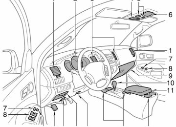
Instrument panel
Steering wheel controls (if equipped)
Volume control buttons (for audio) “ ” buttons (for audio) >> “MODE” button (for audio) Front fog light switch1
Rear differential lock switch1
115V AC Power outlet ON/OFF switch1
Instrument panel light control Headlight and turn signal controls Wiper and washer controls Two-wheel/Four-wheel drive selector1
Audio system Clock Theft deterrent system/Engine immobilizer indicator1
Front passenger seat belt reminder Front passenger occupant classification indicator1
or front passenger airbag ON/OFF indicator1O
Front passenger airbag manual ON/OFF switch1
Air Conditioning controls 12V DC Power outlet Emergency flasher switch 12V DC Power outlet/Cigarette lighter Parking brake lever (stick type)2
Cruise control1
Engine switch Roll sensing curtain shield airbags OFF switch “DAC” (Downhill Assist Control) button1 or clutch start cancel switch1
“VSC OFF” switch1
Power rearview mirror control switches11 If equipped 2 Manual Transmission only.
(Automatic Transmissions are equipped with a parking brake pedal.)
OVERVIEW
Instrument cluster
Tachometer Speedometer Odometer and two trip meters Service indicator and reminder Engine coolant temperature Fuel gauge Trip meter reset knob Gear shift position indicator*
* If equipped
Indicator symbols
Brake system warning1
Driver/Front passenger seat belt reminder1
Charging system warning1
Front passenger occupant classification indicator Low engine oil pressure warning1Malfunction/Check Engine indicator1
Engine oil replacement reminder1
Open door warning1
1 For details, refer to “Service reminder indicators and warning
buzzers,” Section 1-6, 2008 Owner’s Manual.
2 If this light flashes, refer to “Four-wheel drive system,” Section
1-7, 2008 Owner’s Manual.
3 If this light flashes, refer to “Rear differential lock system,”
Airbag SRS warning1
Automatic Transmission fluid temperature warning1
Low Tire Pressure Warning1
Theft deterrent/Engine immobilizer system indicator Roll Sensing Curtain shield Airbags off indicator5Headlight low beam indicator
Headlight high beam indicator
Turn signal indicator
Automatic Transmission indicator (5-speed)/(4-speed) Four-wheel drive indicator2
Low speed four-wheel drive indicator2
Rear differential lock indicator3
Slip indicator Vehicle Stability Control “OFF” indicator warning1
Downhill assist control indicator“AUTO LSD” indicator
Cruise control indicator4
Anti-lock Brake System warning1
Section 1-7, 2008 Owner’s Manual.
4 If this light flashes, refer to “Cruise control,” Section 1-7, 2008
Owner’s Manual.
5 If this light flashes, refer to “Roll sensing of curtain shield
airbags off switch,” Section 1-3, 2008 Owner’s Manual.
OVERVIEW
Keyless entry Locking operation Push
Unlocking operation Push ONCE: Driver door
TWICE: All doors
NOTE: After unlocking, if a door is not opened within 30 seconds, all doors will relock for safety. Panic button Push and hold
Fuel tank door release and cap
Turn
Pull
NOTE: Tighten until one click is heard. If the cap is not tightened enough, Check Engine “ ” indicator may illuminate.
Hood release
Pull up latch and raise hood
Pull
Engine maintenance 4 cylinder (2TR-FE) engine
6 cylinder (1GR-FE) engine
Windshield washer fluid tank Engine coolant reservoir Engine oil filler cap Power steering fluid reservoir Engine oil level dipstick
Note: Regularly scheduled maintenance, including
oil changes, will help extend the life of your vehicle and maintain performance. Please refer to the “Owner’s Warranty Information Booklet,” “Scheduled Maintenance Guide” or “Owner’s Manual Supplement.”