- 2009 Toyota Highlander Owners Manuals
- Toyota Highlander Owners Manuals
- 2004 Toyota Highlander Owners Manuals
- Toyota Highlander Owners Manuals
- 2014 Toyota Highlander Owners Manuals
- Toyota Highlander Owners Manuals
- 2010 Toyota Highlander Owners Manuals
- Toyota Highlander Owners Manuals
- 2005 Toyota Highlander Owners Manuals
- Toyota Highlander Owners Manuals
- 2015 Toyota Highlander Owners Manuals
- Toyota Highlander Owners Manuals
- 2003 Toyota Highlander Owners Manuals
- Toyota Highlander Owners Manuals
- 2001 Toyota Highlander Owners Manuals
- Toyota Highlander Owners Manuals
- 2006 Toyota Highlander Owners Manuals
- Toyota Highlander Owners Manuals
- 2011 Toyota Highlander Owners Manuals
- Toyota Highlander Owners Manuals
- 2002 Toyota Highlander Owners Manuals
- Toyota Highlander Owners Manuals
- 2007 Toyota Highlander Owners Manuals
- Toyota Highlander Owners Manuals
- Download PDF Manual
-
not occur: ● When the speed of the vehicle ahead matches or exceeds your
vehicle speed
● When the vehicle ahead is traveling at an extremely slow speed ● Immediately after the cruise control speed was set ● At the instant the accelerator is applied
HIGHLANDER_U (OM48A12U)
4
4-5. Using the driving support systems
273
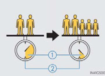
Selecting conventional constant speed control mode Constant speed control mode differs from vehicle-to-vehicle distance control mode. When constant speed control mode is selected, your vehicle will maintain a set speed regardless of whether or not there are other vehicles in the lane ahead.
Press the “ON-OFF” button to activate the cruise control. Press the button again to deacti- vate the cruise control. Switch to constant speed con- trol mode. (Push the lever forward and hold for approximately one sec- ond.) Constant speed control mode indicator will be displayed. When in constant speed control mode, to return to vehicle-to-vehicle dis- tance control mode, push the lever forward again and hold for approxi- mately 1 second. After the desired speed has been set, it is not possible to return to vehicle- to-vehicle distance control mode. If the engine switch is turned off and then turned to IGNITION ON mode again, the vehicle will automatically return to vehicle-to-vehicle distance control mode. Adjusting the speed setting: P. 268
Canceling and resuming the speed setting: P. 270HIGHLANDER_U (OM48A12U)
274
4-5. Using the driving support systems
■Dynamic radar cruise control can be set when
●The shift lever is in the D or range 4 or higher of S has been selected. ●Vehicle speed is above approximately 30 mph (50 km/h).
■Accelerating after setting the vehicle speed
The vehicle can accelerate normally. After acceleration, the set speed resumes. However, during vehicle-to-vehicle distance control mode, the vehi- cle speed may decrease below the set speed in order to maintain the dis- tance to the vehicle ahead.
■Automatic cancelation of vehicle-to-vehicle distance control
Vehicle-to-vehicle distance control driving is automatically canceled in the fol- lowing situations: ●Actual vehicle speed falls below approximately 25 mph (40 km/h). ●Enhanced VSC is activated. ●VSC is activated. ●The sensor cannot operate correctly because it is covered in some way. ●The windshield wipers are operating at high speed (when the wiper switch is
set to the high speed wiper operation position).
If vehicle-to-vehicle distance control driving is automatically canceled for any other reason, there may be a malfunction in the system. Contact your Toyota dealer.
■Automatic cancelation of constant speed control
The cruise control will stop maintaining the vehicle speed in the following situ- ations: ●Actual vehicle speed is more than approximately 10 mph (16 km/h) below
the set vehicle speed. At this time, the memorized set speed is not retained.
●Vehicle speed falls below approximately 25 mph (40 km/h). ●Enhanced VSC is activated. ●VSC is activated.
HIGHLANDER_U (OM48A12U)
4
4-5. Using the driving support systems
275
■Radar sensor and grille cover
Always keep the sensor and grille cover clean to ensure that the vehicle-to- vehicle distance control operates properly. (Some obstructions, such as snow, ice and plastic objects, cannot be detected by the obstruction sensor.) Dynamic radar cruise control is canceled if an obstruction is detected.
Grille cover Radar sensor
■Operation guide display
When the dynamic radar cruise control switch is operated, a guidance display is shown on the multi-information display for a few seconds as to how to oper- ate the dynamic radar cruise control switch or distance switch. (P. 105)
■Warning messages and buzzers for dynamic radar cruise control
Warning messages and buzzers are used to indicate a system malfunction or to inform the driver of the need for caution while driving. (P. 579)
HIGHLANDER_U (OM48A12U)
276
4-5. Using the driving support systems
■Certification for dynamic radar cruise control
For vehicles sold in the U.S.A. FCC ID: HYQDNMWR007
This device complies with Part 15 of the FCC Rules. Operation is subject to the following two conditions : (1) this device may not cause harmful interfer- ence, and (2) this device must accept any interference received, including interference that may cause undesired operation. FCC WARNING Changes or modifications not expressly approved by the party responsible for compliance could void the user’s authority to operate the equipment. Radiofrequency radiation exposure Information: This equipment complies with FCC radiation exposure limits set forth for an uncontrolled environment. This equipment should be installed and operated with minimum distance of 20 cm between the radiator (antenna) and your body. This transmitter must not be co-located or operating in conjunction with any other antenna or transmitter. For vehicles sold in Canada Operation is subject to the following two conditions: (1) this device may not cause interference, and (2) this device must accept any interference, includ- ing interference that may cause undesired operation of the device.HIGHLANDER_U (OM48A12U)
4
4-5. Using the driving support systems
277
WARNING
■Before using dynamic radar cruise control
Do not overly rely on vehicle-to-vehicle distance control. Be aware of the set speed. If automatic deceleration/acceleration is not appropriate, adjust the vehicle speed, as well as the distance between your vehicle and vehicles ahead by applying the brakes etc.
■Cautions regarding the driving assist systems
Observe the following precautions. Failure to do so may cause an accident resulting in death or serious injury. ●Assisting the driver to measure following distance
The dynamic radar cruise control is only intended to help the driver in determining the following distance between the driver’s own vehicle and a designated vehicle traveling ahead. It is not a mechanism that allows care- less or inattentive driving, and it is not a system that can assist the driver in low-visibility conditions. It is still necessary for driver to pay close attention to the vehicle’s surroundings.
●Assisting the driver to judge proper following distance
The dynamic radar cruise control determines whether the following dis- tance between the driver’s own vehicle and a designated vehicle traveling ahead is appropriate or not. It is not capable of making any other type of judgement. Therefore, it is absolutely necessary for the driver to remain vigilant and to determine whether or not there is a possibility of danger in any given situation.
●Assisting the driver to operate the vehicle
The dynamic radar cruise control has no capability to prevent or avoid a collision with a vehicle traveling ahead. Therefore, if there is ever any dan- ger, the driver must take immediate and direct control of the vehicle and act appropriately in order to ensure the safety of all involved.
■To avoid inadvertent cruise control activation
Switch the cruise control off using the “ON-OFF” button when not in use.
HIGHLANDER_U (OM48A12U)
278
4-5. Using the driving support systems
WARNING
■Situations unsuitable for dynamic radar cruise control
Do not use dynamic radar cruise control in any of the following situations. Doing so may result in inappropriate speed control and could cause an acci- dent resulting in death or serious injury. ●In heavy traffic ●On roads with sharp bends ●On winding roads ●On slippery roads, such as those covered with rain, ice or snow ●On steep downhills, or where there are sudden changes between sharp up
and down gradients Vehicle speed may exceed the set speed when driving down a steep hill.
●At entrances to expressways ●When weather conditions are bad enough that they may prevent the sen-
sors from functioning correctly (fog, snow, sandstorm, heavy rain, etc.)
●When an approach warning buzzer is heard often ●When your vehicle is towing a trailer or during emergency towing
■When the sensor may not be correctly detecting the vehicle ahead
Apply the brakes as necessary when any of the following types of vehicles are in front of you. As the sensor may not be able to correctly detect these types of vehicles, the approach warning (P. 272) will not be activated, and a fatal or serious accident may result. ●Vehicles that cut in suddenly ●Vehicles traveling at low speeds ●Vehicles that are not moving ●Vehicles with small rear ends (trailers with no load on board etc.) ●Motorcycles traveling in the same lane
HIGHLANDER_U (OM48A12U)
4
4-5. Using the driving support systems
279
WARNING
■Conditions under which the vehicle-to-vehicle distance control may
not function correctly Apply the brakes as necessary in the following conditions as the radar sen- sor may not be able to correctly detect vehicles ahead, and a fatal or seri- ous accident may result: ●When water or snow thrown up by the surrounding vehicles hinders the
functioning of the sensor
●When your vehicle is pointing upwards (caused by a heavy load in the lug-
gage compartment etc.)
●When the road curves or when the lanes are narrow ●When steering wheel operation or your position in the lane is unstable ●When the vehicle ahead of you decelerates suddenly
■Handling the radar sensor
Observe the following to ensure the cruise control system can function effectively. Otherwise, the system may not function correctly and could result in an accident. ●Keep the sensor and grille cover clean at all times.
Clean the sensor and grille cover with a soft cloth so you do not mark or damage them.
●Do not subject the sensor or surrounding area to a strong impact.
If the sensor moves even slightly off position, the system may malfunction. If the sensor or surrounding area is subject to a strong impact, always have the area inspected and adjusted by your Toyota dealer.
●Do not disassemble the sensor. ●Do not attach accessories or stickers to the sensor, grille cover or sur-
rounding area.
●Do not modify or paint the sensor and grille cover. ●Do not replace them with non-genuine parts.
HIGHLANDER_U (OM48A12U)
280
4-5. Using the driving support systems
LDA (Lane Departure Alert)
Summary of function While driving on a road that has lane markers, this system recognizes the lane markers using a camera as a sensor to alert the driver when the vehicle deviates from its lane. If the system judges that the vehicle has deviated from its lane, it alerts the driver using a buzzer and indications on the multi-informa- tion display. Camera sensor
: If equipped
HIGHLANDER_U (OM48A12U)
4
4-5. Using the driving support systems
281
Turning the LDA system on Vehicles with monochrome dis-
play
Vehicles with color display
Press the LDA switch to activate the system. The LDA indicator and lane lines will come on. Press the switch again to turn the LDA system off. The LDA system will remain on or off even if the engine switch is turned to IGNITION ON mode. Operating conditions ● When the vehicle speed is approximately 32 mph (50 km/h) or
more
● When the lane width is more than approximately 8.2 ft. (2.5 m) ● When driving on a straight road or through a curve with a radius of
more than approximately 328 ft. (100 m)
HIGHLANDER_U (OM48A12U)
282
4-5. Using the driving support systems
Indication on the multi-information display Vehicles with monochrome dis-
Vehicles with color display
play
When the inside of both lane lines turn white: Indicates that both right and left lane markers are recognized.
If the vehicle deviates from the lane, the lane line on the side the vehicle has deviated from will flash. (P. 574)
Vehicles with monochrome dis-
Vehicles with color display
play
When the inside of either lane line turns white: Indicates that the lane marker on the white-marked side is recog- nized.
If the vehicle deviates from the side of a lane with recognized lane mark- ers, the lane line will flash. (P. 574)
HIGHLANDER_U (OM48A12U)
4-5. Using the driving support systems
283
Vehicles with monochrome dis-
Vehicles with color display
play
When both lane lines are shown in fine lines: Indicates that no lane markers are recognized or the LDA system is temporarily canceled.
When the inside of both lane lines are black: Indicates that no lane markers are recognized or the LDA sys- tem is temporarily canceled.
HIGHLANDER_U (OM48A12U)
284
4-5. Using the driving support systems
■Temporary cancelation of the LDA system functions
If any of the following occurs, the LDA system functions will be temporarily canceled. The functions will resume after the necessary operating conditions have returned. ●The turn signal lever is operated. ●The vehicle speed deviates from the operating range of the LDA system
functions.
●When the lane lines cannot be recognized while driving. ●When the lane departure warning function is activated.
The lane departure warning function will not operate again for a several sec- onds after it has been activated, even if the vehicle leaves the lane again.
■The lane departure warning
Depending on the audio system sound level or air conditioning fan noise while the audio system or air conditioning system is in use, it may be difficult to hear the warning sound.
■After the vehicle has been parked in the sun
The LDA system may not be available and a warning message (P. 579) will be displayed for a while after driving has started. When the temperature in the cabin decreases and the temperature around the camera sensor (P. 280) becomes suitable for its operation, the functions will begin to operate.
■If there are lane markers on only one side of the vehicle
The lane departure warning will not operate for the side on which lane mark- ers could not be recognized.
HIGHLANDER_U (OM48A12U)
4
4-5. Using the driving support systems
285
■Conditions in which the function may not operate correctly
In the following situations, the camera sensor may be unable to recognize lane markers causing the lane departure warning function to operate incor- rectly. However, this does not indicate a malfunction. ●When driving through an area with no lane markers, such as a tollbooth, a
crossing or before a ticket checkpoint
●When driving on a sharp curve ●When lane markers are extremely narrow or extremely wide ●When the vehicle leans to one side an unusual amount due to a heavy load
or improper tire inflation pressure
●When the following distance between your vehicle and the vehicle ahead is
extremely short
●When the lane markers are yellow (These may be more difficult for the sys-
tem to recognize compared to white markers.)
●When the lane markers are broken, Botts’ dots (raised pavement markers)
or stones
●When the lane markers are on a curb etc. ●When lane markers are obscured or partially obscured by sand, dirt, etc. ●When there are shadows on the road running parallel with lane markers, or
if a shadow covers the lane markers
●When driving on a particularly bright road surface, such as concrete ●When driving on a road surface that is bright due to reflected light ●When driving in a location where the light level changes rapidly, such as the
entrance to or exit from a tunnel
●When sunlight or the headlights of oncoming vehicles are shining directly
into the camera lens
●When driving on roads that are branching or merging ●When driving on a road surface that is wet due to rain, previous rainfall,
standing water, etc.
●When the vehicle experiences strong up-and-down motion such as when
driving on an extremely rough road or on a seam in the pavement
●When headlight brightness at nighttime is reduced due to dirt on the lenses,
or when the headlights are misaligned
●When driving on winding roads or roads that are uneven ●When driving on rough or unpaved roads
■When changing the tires
Depending on the tires used, sufficient performance may not be maintainable.
■Warning messages for the LDA system
Warning messages are used to indicate a system malfunction or to inform the driver of the need for caution while driving. (P. 578)
HIGHLANDER_U (OM48A12U)
286
4-5. Using the driving support systems
WARNING
■Before using the LDA system
Do not rely solely on the LDA system. The LDA system does not drive the vehicle automatically, nor does it reduce the amount of care you need to take. As such, the driver must always assume full responsibility for under- standing his/her surroundings, for operating the steering wheel to correct the driving line, and for driving safely. Inappropriate or negligent driving could lead to an accident.
■To avoid operating the LDA by mistake
Switch the LDA system off using the LDA switch when not in use.
■Situations unsuitable for LDA system
Do not use the LDA system in any of the following situations. Otherwise, the system may not function correctly and could result in an accident. ●When driving with tire chains, a spare tire, or similar equipment ●When there are objects or structures along the roadside that might be mis- interpreted as lane markers (such as guardrails, a curb, reflector posts, etc.)
●When driving on snowy roads ●When pavement lane markers are difficult to see due to rain, snow, fog,
sand dust, etc.
●When there are visible lines on the pavement from road repairs, or if the
remains of old lane markers are still visible on the road
●When driving on a road with lane closures due to maintenance, or when
driving in a temporary lane
HIGHLANDER_U (OM48A12U)
4-5. Using the driving support systems
287
NOTICE
■To prevent damage to or incorrect operation of the LDA system
●Do not modify the headlights or attach stickers to the surface of the lights. ●Do not modify the suspension or replace it with non-genuine parts. ●Do not install or place anything on the hood or the grille. Also, do not install
a grille guard (bull bars, kangaroo bar etc.).
●If your windshield needs repairs, contact your Toyota dealer.
■Camera sensor
Observe the following to ensure that the LDA system functions correctly. ●Keep the windshield clean at all times.
Performance could be affected if the windshield is dirty, or if raindrops, condensation or ice are adhering to the windshield.
●Do not attach a sticker or other items to the windshield near the camera sensor.
●Do not spill liquid onto the camera sensor ●Do not attach window tinting to the windshield. ●Do not install an antenna in front of the camera lens. ●If the windshield is fogged up, use the windshield defogger to remove fog
from the windshield. When it is cold, using the heater with air blowing to the feet may allow the upper part of the windshield to fog up. This will have a negative effect on the images.
●Do not scratch the camera lens, or let it get dirty.
When cleaning the inside of the windshield, be careful not to get any glass cleaner etc. on the lens. Also, do not touch the lens. For lens repair, contact your Toyota dealer.
●Do not change the installation position or direction of the camera sensor or
remove it. The direction of the camera sensor is precisely adjusted.
●Do not subject the camera sensor to strong impact or force, and do not
disassemble the camera sensor.
●Do not replace windshield with non-genuine windshield.
Contact your Toyota dealer.
HIGHLANDER_U (OM48A12U)
288
4-5. Using the driving support systems
Rear view monitor system Audio system with “APPS” button Refer to the “Navigation and Multimedia System Owner’s Man- ual”. Audio system with “CAR” button The rear view monitor system assists the driver by displaying guide lines and an image of the view behind the vehicle while backing up, for example while parking. The screen illustrations used in this text are intended as examples, and may differ from the image that is actually displayed on the screen.
The rear view image is displayed when the shift position is in R and the engine switch is in “ON” posi- tion.
The rear view monitor system will be deactivated when the shift lever is in any position other than R.
: If equipped
HIGHLANDER_U (OM48A12U)
4
4-5. Using the driving support systems
289
Using the rear view monitor system ■ Screen description
The rear view monitor system screen will be displayed if the shift lever is shifted to R while the engine switch is in “ON” position.
Vehicle width guide lines The line indicates a guide path when the vehicle is being backed straight up. The displayed width is wider than the actual vehicle width. Vehicle center guide lines These lines indicate the estimated vehicle center on the ground. Distance guide line The line shows points approximately 1.5 ft. (0.5 m) (red) from the center of the edge of the bumper. Distance guide line The line shows distance behind the vehicle, a point approximately 3 ft. (1 m) (blue) from the edge of the bumper.
HIGHLANDER_U (OM48A12U)
290
4-5. Using the driving support systems
Rear view monitor system precautions ■ Area displayed on screen
The rear view monitor system displays an image of the view from the bumper of the rear area of the vehicle. To adjust the image on the rear view monitor system screen. (P. 348) • The area displayed on
the screen may vary according to vehicle orientation conditions.
• Objects which are close to either corner of the bumper or under the bumper cannot be seen on the screen.
Corners of bumper
• The camera uses a special lens. The distance of the image that appears
on the screen differs from the actual distance.
• Items which are located higher than the camera may not be displayed
by the monitor.
■ Rear view monitor system camera
The camera for the rear view is monitor system located above the license plate.
● Using the camera If the camera lens becomes dirty, it cannot transmit a clear image. If water droplets, snow or mud adhere to the lens, rinse it with water and wipe with a soft cloth. If the lens is extremely dirty, wash it with a mild cleanser and rinse.
HIGHLANDER_U (OM48A12U)
4
4-5. Using the driving support systems
291
■ Differences between the screen and the actual road
The distance guide lines and the vehicle width guide lines may not actually be parallel with the dividing lines of the parking space, even when they appear to be so. Be sure to check visually. The distances between the vehicle width guide lines and the left and right dividing lines of the parking space may not be equal, even when they appear to be so. Be sure to check visually. The distance guide lines give a distance guide for flat road sur- faces. In any of the following situations, there is a margin of error between the fixed guide lines on the screen and the actual dis- tance/course on the road. ● When the ground behind the vehicle slopes up sharply The distance guide lines will appear to be closer to the vehi- cle than the actual distance. Because of this, objects will appear to be farther away than they actually are. In the same way, there will be a margin of error between the guidelines and the actual distance/course on the road.
HIGHLANDER_U (OM48A12U)
292
4-5. Using the driving support systems
● When the ground behind the vehicle slopes down sharply The distance guide lines will appear to be further from the vehicle than the actual dis- tance. Because of this, objects will appear to be closer than they actually are. In the same way, there will be a margin of error between the guidelines and the actual distance/course on the road.
● When any part of the vehicle sags When any part of the vehicle sags due to the number of pas- sengers or the distribution of the load, there is a margin of error between the fixed guide lines on the screen and the actual distance/course on the road.
A margin of error
■ When approaching three-dimensional objects
The distance guide lines are displayed according to flat surfaced objects (such as the road). It is not possible to determine the posi- tion of three-dimensional objects (such as vehicles) using the dis- tance guide lines. When approaching a three-dimensional object that extends outward (such as the flatbed of a truck), be careful of the following.
HIGHLANDER_U (OM48A12U)
4
4-5. Using the driving support systems
293
● Distance guidelines Visually check the surroundings and the area behind the vehi- cle. On the screen, it appears that a truck is parked at point . However, in reality if you , you will hit back up to point the truck. On the screen, it appears that is closest and is furthest away. However,
in reality, the distance to and farther than
is the same, and
and
is
■ Vehicle width guide lines
Visually check the surroundings and the area behind the vehicle. In the case shown below, the truck appears to be outside of the vehi- cle width guide lines and the vehicle does not look as if it hits the truck. However, the rear body of the truck may actually cross over the vehicle width guide lines. In reality if you back up as guided by the vehicle width guide lines, the vehicle may hit the truck. Vehicle width guide lines
HIGHLANDER_U (OM48A12U)
294
4-5. Using the driving support systems
Things you should know ■ If you notice any symptoms
If you notice any of the following symptoms, refer to the likely cause and the solution, and re-check. If the symptom is not resolved by the solution, have the vehicle inspected by your Toyota dealer.
Likely cause
Solution
The image is difficult to see • The vehicle is in a dark area • The temperature around the lens
is either high or low
• The outside temperature is low • There are water droplets on the
camera
• It is raining or humid • Foreign matter
adhering to the camera
(mud etc.)
is
• There are scratches on the cam-
• Sunlight or headlights are shining
directly into the camera
• The vehicle is under fluorescent lights, mercury
lights, sodium lights etc.
era
If this happens due to these causes, it does not indicate a malfunction. Back up while visually checking the vehicle’s surroundings. (Use the monitor again once conditions have been improved.) To adjust the image on the rear view monitor system screen. (P. 348)
The image is blurry
Dirt or foreign matter (such as water droplets, snow, mud etc.) is adher- ing to the camera.
The image is out of alignment The camera or surrounding area has received a strong impact.
Rinse the camera lens with water and wipe it clean with a soft cloth. Wash with a mild soap if the dirt is stubborn.
Have the vehicle inspected by your Toyota dealer.
HIGHLANDER_U (OM48A12U)
4-5. Using the driving support systems
295
Likely cause
Solution
The fixed guide lines are very far out of alignment • The vehicle is tilted (there is a heavy load on the vehicle, tire pressure is low due to a tire punc- ture, etc.)
If this happens due to these causes, it does not indicate a malfunction. Back up while visually checking the vehicle's surroundings.
• The vehicle is used on an incline. The camera position is out of align- ment.
Have the vehicle inspected by your Toyota dealer.
WARNING
■When using the rear view monitor system
The rear view monitor system is a supplemental device intended to assist the driver when backing up. When backing up, be sure to check visually behind and all around the vehicle before proceeding. Observe the following precautions to avoid an accident that could result in death or serious injuries. ●Never depend on the rear view monitor system entirely when backing up. The image and the position of the guide lines displayed on the screen may differ from the actual state. Use caution, just as you would when backing up any vehicle.
●Be sure to back up slowly, depressing the brake pedal to control vehicle
speed.
●The instructions given are only guidelines.
When and how much to turn the steering wheel will vary according to traf- fic conditions, road surface conditions, vehicle condition, etc. when park- ing. It is necessary to be fully aware of this before using the rear view monitor system.
●When parking, be sure to check that the parking space will accommodate
your vehicle before maneuvering into it.
●Do not use the rear view monitor system in the following cases:
• On icy or slick road surfaces, or in snow • When using tire chains or the compact spare tire • When the back door is not closed completely • On roads that are not flat or straight, such as curves or slopes.
HIGHLANDER_U (OM48A12U)
296
4-5. Using the driving support systems
WARNING
●In low temperatures, the screen may darken or the image may become faint. The image could distort when the vehicle is moving, or you may become unable to see the image on the screen. Be sure to check direct visually and with the mirrors all around the vehicle before proceeding.
●If the tire sizes are changed, the position of the fixed guide lines displayed
on the screen may change.
●The camera uses a special lens. The distances between objects and pedestrians that appear in the image displayed on the screen will differ from the actual distances. (P. 291)
NOTICE
■How to use the camera
●The rear view monitor system may not operate properly in the following
cases. • If the back of the vehicle is hit, the position and mounting angle of the
camera may change.
• As the camera has a water proof construction, do not detach, disassem-
ble or modify it. This may cause incorrect operation.
• Do not strongly rub the camera lens. If the camera lens is scratched, it
cannot transmit a clear image.
• Do not allow organic solvent, car wax, window cleaner or glass coat to
adhere to the camera. If this happens, wipe it off as soon as possible.
• If the temperature changes rapidly, such as when hot water is poured
on the vehicle in cold weather, the system may not operate normally.
• When washing the vehicle, do not apply intensive bursts of water to the camera or camera area. Doing so may result in the camera malfunc- tioning.
• When the camera is used under fluorescent lights, sodium light or mer- cury light etc., the lights and the illuminated areas may appear to flicker. ●Do not expose the camera to strong impact as this could cause a malfunc- tion. If this happens, have the vehicle inspected by your Toyota dealer as soon as possible.
HIGHLANDER_U (OM48A12U)
4-5. Using the driving support systems
297
All-wheel drive lock switch (AWD models)
All-wheel drive lock mode can be used when a large amount of drive power needs to be applied to all the wheels, such as when the vehicle gets stuck in mud and you need to free it.
Press the switch.
extent
possible
The torque of the engine is distrib- uted to the rear wheels to the max- imum in accordance with driving conditions. Pressing the switch again cancels all-wheel drive lock mode and returns the Dynamic Torque Con- trol AWD system to normal mode. (P. 299)
■All-wheel drive lock mode can be operated when
Vehicles without a smart key system The engine switch is in the “ON” position. Vehicles with a smart key system The engine switch is in IGNITION ON mode.
■All-wheel drive lock mode
●All-wheel drive lock mode is canceled when the brakes are applied to
ensure the ABS and VSC systems operate effectively.
●All-wheel drive lock mode is canceled when the vehicle speed exceeds 25
mph (40 km/h).
HIGHLANDER_U (OM48A12U)
298
4-5. Using the driving support systems
Driving assist systems
To help enhance driving safety and performance, the following systems operate automatically in response to various driving situations. Be aware, however, that these systems are supple- mentary and should not be relied upon too heavily when operat- ing the vehicle.
◆ ABS (Anti-lock Brake System)
Helps to prevent wheel lock when the brakes are applied suddenly, or if the brakes are applied while driving on a slippery road surface
◆ Brake assist
Generates an increased level of braking force after the brake pedal is depressed when the system detects a panic stop situation
◆ VSC (Vehicle Stability Control)
Helps the driver to control skidding when swerving suddenly or turning on slippery road surfaces
◆ Enhanced VSC (Enhanced Vehicle Stability Control)
Provides cooperative control of the ABS, TRAC, VSC and EPS. Helps to maintain directional stability when swerving on slippery road surfaces by controlling steering performance.
◆ TRAC (Traction Control)
Helps to maintain drive power and prevent the drive wheels from spinning when starting the vehicle or accelerating on slippery roads
◆ Hill-start assist control
Prevents the vehicle from rolling backward when starting on an incline or slippery slope
◆ Downhill assist control system (AWD models)
P. 304
HIGHLANDER_U (OM48A12U)
4-5. Using the driving support systems ◆ Dynamic Torque Control AWD system (AWD models)
299
Automatically switches from front-wheel drive to all-wheel drive (AWD) according to the driving conditions, helping to ensure reli- able handling and stability. Examples of conditions where the sys- tem will switch to AWD are when cornering, going uphill, starting off or accelerating, and when the road surface is slippery due to snow, rain, etc.
◆ EPS (Electric Power Steering)
Employs an electric motor to reduce the amount of effort needed to turn the steering wheel
◆ PCS (Pre-Collision System) (if equipped)
P. 306
HIGHLANDER_U (OM48A12U)
300
4-5. Using the driving support systems
When the TRAC/VSC systems are operating The slip indicator light will flash while the TRAC/VSC systems are operating.
Disabling the TRAC system If the vehicle gets stuck in mud, dirt or snow, the TRAC system may
reduce power from the engine to the wheels. Pressing to turn the system off may make it easier for you to rock the vehicle in order to free it. To turn the TRAC system off,
quickly press and release
The “TRAC OFF” will be shown on the multi-information display. Press again to turn the system back
on.
HIGHLANDER_U (OM48A12U)
4-5. Using the driving support systems
301
■Turning off both TRAC and VSC systems
for more than 3
To turn the TRAC and VSC systems off, press and hold seconds while the vehicle is stopped. The VSC OFF indicator light will come on and the “TRAC OFF” will be shown on the multi-information display.* Press *: On vehicles with pre-collision system, pre-collision brake assist and pre- collision braking will also be disabled. The pre-collision system warning light will come on and the message will be shown on the multi-information display. (P. 306)
again to turn the systems back on.
■When the message is displayed on the multi-information display show- switch has not been
ing that TRAC has been disabled even if pressed TRAC, hill-start assist control and downhill assist control cannot be operated. Contact your Toyota dealer.
■Sounds and vibrations caused by the ABS, brake assist, TRAC, VSC and
hill-start assist control systems ●A sound may be heard from the engine compartment when the brake pedal is depressed repeatedly, when the engine is started or just after the vehicle begins to move. This sound does not indicate that a malfunction has occurred in any of these systems.
●Any of the following conditions may occur when the above systems are
operating. None of these indicates that a malfunction has occurred. • Vibrations may be felt through the vehicle body and steering. • A motor sound may be heard after the vehicle comes to a stop. • The brake pedal may pulsate slightly after the ABS is activated. • The brake pedal may move down slightly after the ABS is activated.
■EPS operation sound
When the steering wheel is operated, a motor sound (whirring sound) may be heard. This does not indicate a malfunction.
■Automatic reactivation of TRAC and VSC systems
After turning the TRAC and VSC systems off, the systems will be automati- cally re-enabled in the following situations: ●Vehicles without a smart key system: When the engine switch is turned to
the “LOCK” position Vehicles with a smart key system: When the engine switch is turned off
●If only the TRAC system is turned off, the TRAC will turn on when vehicle
speed increases If both the TRAC and VSC systems are turned off, automatic re-enabling will not occur when vehicle speed increases.
HIGHLANDER_U (OM48A12U)
302
4-5. Using the driving support systems
■Reduced effectiveness of the EPS system
The effectiveness of the EPS system is reduced to prevent the system from overheating when there is frequent steering input over an extended period of time. The steering wheel may feel heavy as a result. Should this occur, refrain from excessive steering input or stop the vehicle and turn the engine off. The EPS system should return to normal within 10 minutes.
■Operating conditions of hill-start assist control
When the following four conditions are met, the hill-start assist control will operate: ●The shift lever is in a position other than P or N (when starting off forward/
backward on an upward incline).
●The vehicle is stopped. ●The accelerator pedal is not depressed. ●The parking brake is not engaged.
■Automatic system cancelation of hill-start assist control
The hill-start assist control will turn off in any of the following situations: ●The shift lever is moved to P or N. ●The accelerator pedal is depressed. ●The parking brake is engaged. ●Approximately 2 seconds elapse after the brake pedal is released.
WARNING
■The ABS does not operate effectively when
●The limits of tire gripping performance have been exceeded (such as
excessively worn tires on a snow covered road).
●The vehicle hydroplanes while driving at high speed on wet or slick roads. ■Stopping distance when the ABS is operating may exceed that of nor-
mal conditions The ABS is not designed to shorten the vehicle’s stopping distance. Always maintain a safe distance from the vehicle in front of you, especially in the following situations: ●When driving on dirt, gravel or snow-covered roads ●When driving with tire chains ●When driving over bumps in the road ●When driving over roads with potholes or uneven surfaces
HIGHLANDER_U (OM48A12U)
4
4-5. Using the driving support systems
303
WARNING
■TRAC may not operate effectively when
Directional control and power may not be achievable while driving on slip- pery road surfaces, even if the TRAC system is operating. Drive the vehicle carefully in conditions where stability and power may be lost.
■Hill- start assist control
●Do not overly rely on hill-start assist control. Hill-start assist control may
not operate effectively on steep inclines and roads covered with ice.
●Unlike the parking brake, hill-start assist control is not intended to hold the vehicle stationary for an extended period of time. Do not attempt to use hill-start assist control to hold the vehicle on an incline, as doing so may lead to an accident.
■When the VSC is activated
The slip indicator light flashes. Always drive carefully. Reckless driving may cause an accident. Exercise particular care when the indicator light flashes.
■When the TRAC/VSC systems are turned off
Be especially careful and drive at a speed appropriate to the road condi- tions. As these are the systems to help ensure vehicle stability and driving force, do not turn the TRAC/VSC systems off unless necessary.
■Replacing tires
Make sure that all tires are of the specified size, brand, tread pattern and total load capacity. In addition, make sure that the tires are inflated to the recommended tire inflation pressure level. The ABS, TRAC and VSC systems will not function correctly if different tires are installed on the vehicle. Contact your Toyota dealer for further information when replacing tires or wheels.
■Handling of tires and the suspension
Using tires with any kind of problem or modifying the suspension will affect the driving assist systems, and may cause a system to malfunction.
HIGHLANDER_U (OM48A12U)
304
4-5. Using the driving support systems
Downhill assist control system (AWD mod- els)
With the downhill assist control system, the vehicle is able to descend a steep hill, maintaining a constant low speed of about 3 mph (5 km/h) without brake pedal operation.
■ Activating the downhill assist control system
Press the “DAC” switch.
The downhill assist control sys- tem indicator will come on to indicate that the downhill assist control system is activated. Pressing the switch again turns the system off.
While the downhill assist control system is operating
The slip indicator will flash to indi- cate that the downhill assist con- trol system is operating, and the stop lights and high mounted stoplight will turn on.
■Conditions in which the downhill assist control system does not operate ●In the following situations, the downhill assist control system indicator flashes and the downhill assist control system does not operate or will stop operating: • The shift lever is not in 1 range of S mode or R. • The vehicle speed is higher than 15 mph (25 km/h).
●If the accelerator or brake pedal is depressed, the downhill assist control system will stop operating with the downhill assist control system indicator still on.
HIGHLANDER_U (OM48A12U)
4
4-5. Using the driving support systems
305
■If the “DAC” switch is turned off during operation of the downhill assist
control system The downhill assist control system gradually ceases operation. The downhill assist control system indicator will flash during the canceling operation, and then go off when the system is fully off.
■Downhill assist control system operation sound
●A sound may be heard from the engine compartment during operation of the downhill assist control system. This sound does not indicate a malfunction. ●If the accelerator or brake pedal is depressed during operation of the down- hill assist control system, a sound caused by the release of system opera- tion may be heard, or you may feel the brake pedal push-back. This does not indicate a malfunction.
■When the downhill assist control system operates continuously
The brake actuator may overheat. In that case, the downhill assist control system will stop operating, a buzzer will sound and the downhill assist control system indicator will start flashing. Refrain from using the system until the downhill assist control system indicator stays on. (There is no problem with continuing to drive normally.)
■If the slip indicator comes on
It may indicate a malfunction in the system. Contact your Toyota dealer.
WARNING
■Conditions which may affect the downhill assist control system opera-
tion ●Do not rely too heavily on the downhill assist control system. On extremely steep inclines, icy surfaces or muddy roads, the vehicle may slip and the system may not be able to maintain the constant low vehicle speed of about 3 mph (5 km/h), leading to an accident causing death or serious injury.
●Do not shift the shift lever to R while driving forward, or to D while driving backward. Doing so may cause the wheels to lock up, leading to an acci- dent causing death or serious injury. In addition, excessive stress will be applied to the automatic transmission, possibly resulting in damage.
HIGHLANDER_U (OM48A12U)
306
4-5. Using the driving support systems
PCS (Pre-Collision System) When the radar sensor detects that a frontal collision is highly likely or even unavoidable, safety systems such as the brakes and seat belts are automatically engaged to lessen impact as well as vehicle damage. The pre-collision system can be turned on and off as necessary by operating the switch. (P. 307)
◆ Pre-collision warning
When a high possibility of a frontal collision is detected, the pre-collision system warning light flashes, a buzzer sounds and a message is shown on the multi-information display to urge the driver to take evasive action.
◆ Pre-collision brake assist
When there is a high possibility of a frontal collision, the system applies greater braking force in relation to how strongly the brake pedal is depressed. The system may not warn the driver using a warning light, warning display and buzzer when the system detects and judges braking operations.
◆ Pre-collision braking
When there is a high possibility of a frontal collision, the system warns the driver using a warning light, warning display and buzzer. If the system determines that a collision is unavoidable, the brakes are automatically applied to reduce the collision speed.
: If equipped
HIGHLANDER_U (OM48A12U)
4
4-5. Using the driving support systems
307
Disabling pre-collision system
Enabled Disabled The pre-collision system warning light comes on when pre-collision system is disabled.
Radar sensor The radar sensor detects vehi- cles or other obstacles on or near the road ahead and determines whether a collision is imminent based on the position, speed, and heading of the obstacles.
HIGHLANDER_U (OM48A12U)
308
4-5. Using the driving support systems
■The pre-collision system is operational when
The PCS OFF switch is not pressed and the following conditions are met: ●Pre-collision warning:
• Vehicle speed is greater than about 10 mph (15 km/h). • The speed at which your vehicle is approaching the obstacle or the vehi-
cle running ahead of you is greater than about 10 mph (15 km/h).
●Pre-collision brake assist:
• The VSC OFF switch is not pressed. • Vehicle speed is greater than about 19 mph (30 km/h). • The speed at which your vehicle is approaching the obstacle or the vehi-
cle running ahead of you is greater than about 19 mph (30 km/h).
• The brake pedal is depressed.
●Pre-collision braking:
• The VSC OFF switch is not pressed. • Vehicle speed is greater than about 10 mph (15 km/h). • The speed at which your vehicle is approaching the obstacle or the vehi-
cle running ahead of you is greater than about 10 mph (15 km/h).
■Conditions that may trigger the system even if there is no danger of a
collision ●When there is an object by the roadside at the entrance to a curve ●When passing an oncoming vehicle on a curve ●When driving over a narrow iron bridge ●When there is a metal object on the road surface ●When driving on an uneven road surface ●When passing an oncoming vehicle on a left-turn ●When your vehicle rapidly closes on the vehicle in front ●When a grade separation/interchange, sign, billboard, or other structure
appears to be directly in the vehicle’s line of travel
●When there is a metal plate in the road in front of the vehicle on a downhill
slope
●When climbing a steep hill causes an overhead billboard or other metallic
structure to appear directly in the vehicle’s line of travel
●When driving under an overpass ●When an extreme change in vehicle height occurs ●When passing through certain toll gates ●When passing through a tunnel ●When the radar sensor moves off position due to its surrounding area being
subjected to a strong impact
When the system is activated in the situations described above, there is also a possibility that the brakes will be applied with a force greater than normal.
HIGHLANDER_U (OM48A12U)
4-5. Using the driving support systems
309
■Obstacles not detected
The sensor cannot detect plastic obstacles such as traffic cones. There may also be occasions when the sensor cannot detect pedestrians, animals, bicy- cles, motorcycles, trees, or snowdrifts.
■Situations in which the pre-collision system does not function properly
The system may not function effectively in situations such as the following: ●On roads with sharp bends or uneven surfaces ●If a vehicle suddenly moves in front of your vehicle, such as at an intersec-
tion
●If a vehicle suddenly cuts in front of your vehicle, such as when overtaking ●In inclement weather such as heavy rain, fog, snow or sand storms ●If the vehicle is skidding when VSC is not operating ●When an extreme change in vehicle height occurs ●When only part of your vehicle’s front end collides with, or contacts, a vehi-
cle or object in a frontal collision
●When the radar sensor moves off position due to its surrounding area being
subjected to a strong impact
■Automatic cancelation of the pre-collision system
When a malfunction occurs due to sensor contamination, etc. that results in the sensors being unable to detect obstacles, the pre-collision system will be automatically disabled. In this case, the system will not activate even if there is a collision possibility.
■When there is a malfunction in the system
The pre-collision system warning light will flash and warning messages will be displayed. (P. 564, 579)
HIGHLANDER_U (OM48A12U)
310
4-5. Using the driving support systems
■Certification for the pre-collision system
For vehicles sold in the U.S.A. FCC ID : HYQDNMWR007
This device complies with Part 15 of the FCC Rules. Operation is subject to the following two conditions :(1) this device may not cause harmful interfer- ence, and (2) this device must accept any interference received, including interference that may cause undesired operation. FCC WARNING Changes or modifications not expressly approved by the party responsible for compliance could void the user’s authority to operate the equipment. Radiofrequency radiation exposure Information: This equipment complies with FCC radiation exposure limits set forth for an uncontrolled environment. This equipment should be installed and operated with minimum distance of 20 cm between the radiator (antenna) and your body. This transmitter must not be co-located or operating in conjunction with any other antenna or transmitter. For vehicles sold in Canada Operation is subject to the following two conditions: (1) this device may not cause interference, and (2) this device must accept any interference, includ- ing interference that may cause undesired operation of the device.HIGHLANDER_U (OM48A12U)
4
4-5. Using the driving support systems
311
WARNING
■Limitations of the pre-collision system
Do not overly rely on the pre-collision system. Always drive safely, taking care to observe your surroundings and checking for any obstacles or other road hazards. Failure to do so may cause an accident resulting in death or serious injury.
■When the sensor may not be correctly detecting the vehicle ahead
Apply the brakes as necessary in any of the following situations: ●When water or snow thrown up by the surrounding vehicles hinders the
functioning of the sensor
●When your vehicle is pointing upwards (caused by a heavy load in the lug-
gage compartment etc.)
●Vehicles that cut in suddenly ●Vehicles with small rear ends (trailers with no load on board etc.) ●Motorcycles traveling in the same lane
■Handling the radar sensor
Observe the following to ensure the pre-collision system can function effec- tively. Otherwise, the system may not function correctly and could result in an accident. ●Keep the sensor and grille cover clean at all times.
Clean the sensor and grille cover with a soft cloth so you do not mark or damage them.
●Do not subject the sensor or surrounding area to a strong impact.
If the sensor moves even slightly off position, the system may malfunction. If the sensor or surrounding area is subject to a strong impact, always have the area inspected and adjusted by your Toyota dealer.
●Do not disassemble the sensor. ●Do not attach accessories or stickers to the sensor, grille cover or sur-
rounding area.
●Do not modify or paint the sensor and grille cover. ●Do not replace them with non-genuine parts.
HIGHLANDER_U (OM48A12U)
312
4-5. Using the driving support systems
WARNING
■Cautions regarding the assist contents of the system
By means of alarms and brake control, the pre-collision system is intended to assist the driver in avoiding collisions through the process of LOOK- JUDGE-ACT. There are limits to the degree of assistance the system can provide, so please keep in mind the following important points. ●Assisting the driver in watching the road
The pre-collision system is only able to detect obstacles directly in front of the vehicle, and only within a limited range. It is not a mechanism that allows careless or inattentive driving, and it is not a system that can assist the driver in low-visibility conditions. It is still necessary for the driver to pay close attention to the vehicle’s surroundings.
●Assisting the driver in making correct judgment
When attempting to estimate the possibility of a collision, the only data available to the pre-collision system is that from obstacles it has detected directly in front of the vehicle. Therefore, it is absolutely necessary for the driver to remain vigilant and to determine whether or not there is a possi- bility of collision in any given situation.
●Assisting the driver in taking action
The pre-collision system’s braking assist feature is designed to help reduce the severity of a collision, and so only acts when the system has judged that a collision is unavoidable. This system by itself is not capable of automatically avoiding a collision or bringing the vehicle to a stop safely. For this reason, when encountering a dangerous situation the driver must take direct and immediate action in order to ensure the safety of all involved.
HIGHLANDER_U (OM48A12U)
4-5. Using the driving support systems
313
BSM (Blind Spot Monitor)
Summary of the Blind Spot Monitor The Blind Spot Monitor is a system that has 2 functions; ● The Blind Spot Monitor function
Assists the driver in making the decision when changing lanes
● The Rear Cross Traffic Alert function
Assists the driver when backing up
These functions use same sensors.
BSM main switch Pressing the switch turns the system on or off. When the switch is set to on, the switch’s indicator illuminates and the buzzer sounds. Common switch for Blind Spot Monitor function and Rear Cross Traffic Alert func- tion.
: If equipped
HIGHLANDER_U (OM48A12U)
314
4-5. Using the driving support systems
Outside rear view mirror indicators Blind Spot Monitor function: When a vehicle is detected in the blind spot, the outside rear view mirror indicator comes on while the turn signal lever is not operated and the out- side rear view mirror indicator flashes while the turn signal lever is oper- ated. Rear Cross Traffic Alert function: When a vehicle approaching from the right or left rear of the vehicle is detected, the outside rear view mirror indicators flash. Rear Cross Traffic Alert buzzer (Rear Cross Traffic Alert function only) When a vehicle approaching from the right or left rear of the vehicle is detected, a buzzer sounds from behind the left-hand third seat.
■The outside rear view mirror indicators visibility
When under strong sunlight, the outside rear view mirror indicator may be dif- ficult to see.
■Rear Cross Traffic Alert buzzer hearing
Rear Cross Traffic Alert function may be difficult to hear over loud noises such as high audio volume.
■When there is a malfunction in the Blind Spot Monitor
If a system malfunction is detected due to any of the following reasons, warn- ing message will be displayed: (P. 578, 579) ●There is a malfunction with the sensors ●The sensors have become dirty ●The outside temperature is extremely high or low ●The sensor voltage has become abnormal
HIGHLANDER_U (OM48A12U)
4
4-5. Using the driving support systems
315
■Certification for the Blind Spot Monitor
For vehicles sold in the U.S.A. FCC ID: OAYSRR2A This device complies with part 15 of the FCC Rules. Operation is subject to the following two conditions: (1)This device may not cause harmful interference, and (2)this device must accept any interference received, including interference
that may cause undesired operation.
FCC Warning Changes or modifications not expressly approved by the party responsible for compliance could void the user’s authority to operate the equipment. For vehicles sold in Canada Applicable law: Canada 310
This device complies with Industry Canada licence-exempt RSS standard(s). Operation is subject to the following two conditions: (1) this device may not cause interference, and (2) this device must accept any interference, includ- ing interference that may cause undesired operation of the device. Frequency bands: 24.05-24.25 GHz Output power: less than 20 milliwattsHIGHLANDER_U (OM48A12U)
316
4-5. Using the driving support systems
WARNING
■Handling the radar sensor
One Blind Spot Monitor sensor is installed inside the left and right side of the vehicle rear bumper respectively. Observe the following to ensure the Blind Spot Monitor can function correctly. ●Keep the sensor and its surrounding
area on the bumper clean at all times.
●Do not subject the sensor or surrounding area on the bumper to a strong impact. If the sensor moves even slightly off position, the system may mal- function and vehicles that enter the detection area may not be detected. If the sensor or surrounding area is subject to a strong impact, always have the area inspected by your Toyota dealer.
●Do not disassemble the sensor. ●Do not attach accessories or stickers to the sensor or surrounding area on
the bumper.
●Do not modify the sensor or surrounding area on the bumper. ●Do not paint the sensor or surrounding area on the bumper.
HIGHLANDER_U (OM48A12U)
4
4-5. Using the driving support systems
317
The Blind Spot Monitor function The Blind Spot Monitor function uses radar sensors to detect vehicles that are traveling in an adjacent lane in the area that is not reflected in the outside rear view mirror (the blind spot), and advises the driver of the vehicles existence via the outside rear view mirror indicator.
The Blind Spot Monitor function detection areas The areas that vehicles can be detected in are outlined below. The range of the detection area extends to:
Approximately 11.5 ft. (3.5 m) from the side of the vehicle The first 1.6 ft. (0.5 m) from the side of the vehicle is not in the detection area Approximately 9.8 ft. (3 m) from the rear bumper Approximately 3.3 ft. (1 m) for- ward of the rear bumper
WARNING
■Cautions regarding the use of the system
The driver is solely responsible for safe driving. Always drive safely, taking care to observe your surroundings. The Blind Spot Monitor function is a supplementary function which alerts the driver that a vehicle is present in the blind spot. Do not overly rely on the Blind Spot Monitor function. The function cannot judge if it is safe to change lanes, therefore over reliance could cause an accident resulting in death or serious injury. According to conditions, the system may not function correctly. Therefore the driver’s own visual confirmation of safety is necessary.
HIGHLANDER_U (OM48A12U)
318
4-5. Using the driving support systems
■The Blind Spot Monitor function is operational when
●The BSM main switch is set to on ●Vehicle speed is greater than approximately 10 mph (16 km/h).
■The Blind Spot Monitor function will detect a vehicle when
●A vehicle in an adjacent lane overtakes your vehicle. ●Another vehicle enters the detection area when it changes lanes.
■Conditions under which the Blind Spot Monitor function will not detect a
vehicle The Blind Spot Monitor function is not designed to detect the following types of vehicles and/or objects: ●Small motorcycles, bicycles, pedestrians etc.* ●Vehicles traveling in the opposite direction ●Guardrails, walls, signs, parked vehicles and similar stationary objects* ●Following vehicles that are in the same lane* ●Vehicles driving 2 lanes across from your vehicle* *: Depending on conditions, detection of a vehicle and/or object may occur.
HIGHLANDER_U (OM48A12U)
4-5. Using the driving support systems
319
■Conditions under which the Blind Spot Monitor function may not func-
tion correctly ●The Blind Spot Monitor function may not detect vehicles correctly in the fol-
lowing conditions: • During bad weather such as heavy rain, fog, snow etc. • When ice or mud etc. is attached to the rear bumper • When driving on a road surface that is wet due to rain, standing water etc. • When there is a significant difference in speed between your vehicle and
the vehicle that enters the detection area
• When a vehicle is in the detection area from a stop and remains in the
detection area as your vehicle accelerates
• When driving up or down consecutive steep inclines, such as hills, a dip
in the road etc.
vehicle
• When multiple vehicles approach with only a small gap between each
• When vehicle lanes are wide, and the vehicle in the next lane is too far
• When the vehicle that enters the detection area is traveling at about the
away from your vehicle
same speed as your vehicle
• When there is a significant difference in height between your vehicle and
the vehicle that enters the detection area
• Directly after the BSM main switch is set to on • When towing a trailer
●Instances of the Blind Spot Monitor function unnecessarily detecting a vehi-
cle and/or object may increase under the following conditions: • When there is only a short distance between your vehicle and a guardrail,
• When there is only a short distance between your vehicle and a following
• When vehicle lanes are narrow and a vehicle driving 2 lanes across from
your vehicle enters the detection area
• When items such as a bicycle carrier are installed on the rear of the vehi-
wall etc.
vehicle
cle
HIGHLANDER_U (OM48A12U)
320
4-5. Using the driving support systems
The Rear Cross Traffic Alert function The Rear Cross Traffic Alert functions when your vehicle is in reverse. It can detect other vehicles approaching from the right or left rear of the vehicle. It uses radar sensors to alert the driver of the other vehi- cle’s existence through flashing the outside rear view mirror indicators and sounding a buzzer.
Approaching vehicles
Detection areas
WARNING
■Cautions regarding the use of the system
The driver is solely responsible for safe driving. Always drive safely, taking care to observe your surroundings. The Rear Cross Traffic Alert function is only an assist and is not a replace- ment for careful driving. Driver must be careful when backing up, even when using Rear Cross Traffic Alert function. The driver’s own visual confir- mation of behind you and your vehicle is necessary and be sure there are no pedestrians, other vehicles etc. before backing up. Failure to do so could cause death or serious injury. According to conditions, the system may not function correctly. Therefore the driver’s own visual confirmation of safety is necessary.
HIGHLANDER_U (OM48A12U)
4
4-5. Using the driving support systems
321
The Rear Cross Traffic Alert function detection areas The areas that vehicles can be detected in are outlined below.
To give the driver a more consistent time to react, the buzzer can alert for faster vehicles from farther away. Example:
Approaching vehicle
Speed
Fast Slow
18 mph (28 km/h) 5 mph (8 km/h)
Approximate alert distance 65 ft. (20 m) 18 ft. (5.5 m)
■The Rear Cross Traffic Alert function is operational when
●The BSM main switch is set to on. ●The shift lever is in R. ●Vehicle speed is less than approximately 5 mph (8 km/h). ●Approaching vehicle speed is between approximately 5 mph (8 km/h) and
18 mph (28 km/h).
HIGHLANDER_U (OM48A12U)
322
4-5. Using the driving support systems
■Conditions under which the Rear Cross Traffic Alert function will not
detect a vehicle The Rear Cross Traffic Alert function is not designed to detect the following types of vehicles and/or objects. ●Small motorcycles, bicycles, pedestrians etc.* ●Vehicles approaching from directly behind ●Guardrails, walls, signs, parked vehicles and similar stationary objects* ●Vehicles moving away from your vehicle ●Vehicles approaching from the parking spaces next to your vehicle* ●Vehicles backing up in the parking space next to your vehicle* *: Depending on conditions, detection of a vehicle and/or object may occur. ■Conditions under which the Rear Cross Traffic Alert function may not
function correctly The Rear Cross Traffic Alert function may not detect vehicles correctly in the following conditions: ●When ice or mud etc. is attached to the rear bumper ●During bad weather such as heavy rain, fog, snow etc. ●When multiple vehicles approach continuously ●Shallow angle parking ●When a vehicle is approaching at high speed ●When parking on a steep incline, such as hills, a dip in the road etc. ●Directly after the BSM main switch is set to on ●Directly after the engine is started with the BSM main switch on ●When towing a trailer ●Vehicles that the sensors cannot detect
because of obstacles
HIGHLANDER_U (OM48A12U)
4-6. Driving tips
323
Winter driving tips
Carry out the necessary preparations and inspections before driving the vehicle in winter. Always drive the vehicle in a man- ner appropriate to the prevailing weather conditions.
Preparation for winter ● Use fluids that are appropriate to the prevailing outside tempera-
tures. • Engine oil • Engine coolant • Washer fluid
● Have a service technician inspect the condition of the battery. ● Have the vehicle fitted with four snow tires or purchase a set of tire
chains for the front tires.
Ensure that all tires are the same size and brand, and that chains match the size of the tires.
HIGHLANDER_U (OM48A12U)