- 2006 Toyota Camry Owners Manuals
- Toyota Camry Owners Manuals
- 1998 Toyota Camry Owners Manuals
- Toyota Camry Owners Manuals
- 2015 Toyota Camry Owners Manuals
- Toyota Camry Owners Manuals
- 2001 Toyota Camry Owners Manuals
- Toyota Camry Owners Manuals
- 2010 Toyota Camry Owners Manuals
- Toyota Camry Owners Manuals
- 2004 Toyota Camry Owners Manuals
- Toyota Camry Owners Manuals
- 2005 Toyota Camry Owners Manuals
- Toyota Camry Owners Manuals
- 1997 Toyota Camry Owners Manuals
- Toyota Camry Owners Manuals
- 2000 Toyota Camry Owners Manuals
- Toyota Camry Owners Manuals
- 2002 Toyota Camry Owners Manuals
- Toyota Camry Owners Manuals
- 2012 Toyota Camry Owners Manuals
- Toyota Camry Owners Manuals
- 1996 Toyota Camry Owners Manuals
- Toyota Camry Owners Manuals
- 2003 Toyota Camry Owners Manuals
- Toyota Camry Owners Manuals
- 2009 Toyota Camry Owners Manuals
- Toyota Camry Owners Manuals
- 2008 Toyota Camry Owners Manuals
- Toyota Camry Owners Manuals
- Download PDF Manual
-
inflates and the impact could cause death or serious injury to the child. For the installation of a child restraint sys- tem, see “Child restraint” in this chapter.
concerning
instructors
D Do not lean against the front door when the vehicle is in use. The side airbag inflates with considerable speed and force; you may be killed or seriously injured.
D Do not apply excessive weight to the outer side of the front seats on vehicles with side airbags.
D The child head should not be leaned against the vicinity of the part where the side airbag acti- vates.
D Do not attach a cup holder or any other device on or around the door. When the side airbag inflates, the cup holder or any other device will be thrown with great force or the side airbag may not activate cor- rectly, resulting in death or serious injury. Likewise, the driver and front passenger should not hold things in their arms or on their knees.
51
NOTICE
consulting
Do not perform any of the following changes without your Toyota dealer. Such changes can interfere with proper operation of the SRS airbag system in some cases. z Installation of electronic items such as a mobile two−way radio, cassette tape player or compact disc player z Modification of the suspension sys-
tem
z Modification of the side structure of
the passenger compartment
z Repairs made on or near the con-
sole or front seat
for
D Do not use accessories
the seats which cover the parts where the side airbags should inflate. Such accessories may prevent the side airbags from activating correct- ly, causing death or serious injury. D Do not modify or replace the seats or surface of the front seats with the side airbags. Such changes may disable the system or cause the side airbags to inflate, resulting in death or serious injury. Consult your Toyota dealer.
Failure to follow these instructions can result in death or serious inju- ries.
52
following
conditions occurs,
This SRS side airbag system has a service reminder indicator to inform the driver of operating problems. If either of the this indicates a malfunction of the airbags. Contact your Toyota dealer as soon as possible to service the vehicle. D The light does not come on when the ignition key is turned to the “ACC” or “ON” position, or remains on.
D The light comes on or flashes while
driving.
NOTICE
Do not disconnect the battery cables before contacting your Toyota dealer.
In the following cases, contact your Toyota dealer as soon as possible: D The SRS side airbags have been in-
flated.
D The portion of the doors (shaded in the illustration) were involved in an acci- dent that did not cause the SRS side airbags to inflate.
D The surface of the seats with the side airbag (shaded is scratched, cracked, or otherwise dam- aged.
illustration)
the
in
Child restraint— —Child restraint precautions Toyota strongly urges the use of child restraint systems for children small enough to use them. The laws of all fifty states in the U.S.A. and Canada now require the use of a child restraint system. Your vehicle conforms to SAEJ1819. If a child is too large for a child restraint system, the child should sit in the rear seat and must be restrained using the vehicle’s seat belt. See ”Seat belts” for details.
CAUTION
D For effective protection in automo- bile accidents and sudden stops, children must be properly re- strained using a seat belt or child restraint system depending on the age and size of the child. Holding a child in your arms is not a sub- stitute for a child restraint system. In an accident, the child can be crushed against the windshield, or between you and the vehicle’s inte- rior.
53
D A forward−facing child restraint sys- tem should be put on the front seat only when it is unavoidable. Always move the seat as far back as pos- sible, because the force of a de- ploying airbag could cause death or serious injury to the child. Do not allow the child to lean against the front door or around the front door even if the child is seated in the child restraint system. It is danger- ous if the side airbag inflates, and the impact could cause death or serious injury to the child.
D Make sure that you have complied with all installation instructions pro- vided restraint manufacturer and that the system is properly secured.
child
the
by
—Child restraint system A child restraint system for a small child or baby must itself be properly restrained on the seat with the lap por- tion of the lap/shoulder belt. You must carefully consult the manufacturer’s in- structions which accompany your child restraint system. To provide proper restraint, use a child restraint system following the manufactur- er’s instructions about the appropriate age and size of the child for the restraint sys- tem. Install the child restraint system correctly following the instructions provided by its manufacturer of the system. General di- rections are also provided under the fol- lowing illustrations. The child restraint system should be installed on the rear seat. According to accident statistics, the child is safer when properly restrained in the rear seat than in the front seat.
D Toyota strongly urges use of a proper child restraint system which conforms to the size of the child, and is put on the rear seat. Accord- ing to accident statistics, the child is safer when properly restrained in the rear seat than in the front seat. D Never put a rear−facing child re- straint system on the front seat. In the event of an accident, the force of the rapid inflation of the airbag can cause death or serious injury if a rear−facing child restraint system is put on the front seat.
D Unless it is unavoidable, do not put the
restraint system on
a child front seat.
54
CAUTION
D Never put a rear−facing child re- straint system on the front seat. In the event of an accident, the force of the rapid inflation of the airbag can cause death or serious injury if a rear−facing child restraint system is put on the front seat.
D Unless it is unavoidable, do not put the
restraint system on
a child front seat.
D A forward−facing child restraint sys- tem should be put on the front seat only when it is unavoidable. Always move the seat as far back as pos- sible, because the force of a de- ploying airbag could cause death or serious injury to the child. Do not allow the child to lean against the front door or around the front door even if the child is seated in the child restraint system. It is danger- ous if the side airbag inflates, and the impact could cause death or serious injury to the child.
D After
installing the child restraint system, make sure it is secured in place following the manufacturer’s instructions. If it is not restrained securely, it may cause death or se- rious the event of a sudden stop or accident.
the child
injury
to
in
it
in
from
injuring passengers
When not using the child restraint system, keep it secured with the seat belt or place it in the trunk or somewhere other than the passenger compartment. This will pre- vent the event of a sudden stop or accident. Your vehicle has anchors for securing the top strap of a child restraint system. The anchor nuts are welded beneath the sheet metal to permit installation of an anchor bracket for a child restraint system. To install an anchor bracket, use an 8 mm 1.25 mm coarse thread metric bolt and 15 mm (0.6 in.) spacer. Note that the bolts accompanying many child re- straint systems are not metric. You can damage the anchor nuts on your vehicle if you force bolts with different thread into the anchor nuts.
30 mm
For instructions about how to install the anchor bracket, see ”Top strap anchors and locations”. If your child restraint system does not provide any of the necessary parts, you can purchase the from your Toyota dealer. * CRS installation kit
following
items
(Part No. 04731−22012)—contains 1 bolt, 3 types of spacers and 1 locking clip.
* Bolt (Part No. 91511−60830)
55
—Built−in child restraint
56
The built−in child restraint system mainly consists of a child seat integrated in the rear seat and 5−point seat belts. Refer to the illustration to become familiar with the parts of the system. This child restraint system conforms to U.S. Motor Vehicle Safety Standard No.213 and Canada Motor Vehicle Safety Standard No.213.4. 1. Shoulder belts
2. Head restraint lock release button
3. Storage bag (for the head restraint and
upper pad)
4. Head restraint and upper pad
(for the rear seat)
5. Maximum shoulder height indicator
label
6. Removable pad
7. Seat belt buckle
8. Seat belt release strap (black)
9. Seat belt adjustment strap (gray tab)
10. Child seat cushion
11. Seat belt buckle release button
12. Seat belt tabs
13. Owner’s manual supplement
14. Shoulder belt clip
is
This child restraint is designed for use only by children who weigh between 10
and 30 kg (22.1 and 66.1 pounds), and whose height is between 85 and 127 cm (33.5 and 50.0 inches). The child should be at least one year old and must be capable of sitting up- right alone and whose shoulder height is at or below the maximum shoulder height indicator. It important to use a rear−facing child restraint until the child is about a year old. A rear−facing restraint gives the child’s head, neck and body the support they would need in a crash. See ”—Child restraint system” for more information. If your child’s shoulders are above the indicator position, do not use the built− in child restraint. Your child should use the vehicle’s seat belts. According to accident statistics, children are safer when properly restrained in the rear seat than in the front seat.CAUTION
Make sure the child is securely re- strained with the built−in child re- straint. Failure to follow the instruc- tions provided here and also in the owner’s manual supplement on the use of this child restraint system can result serious injuries when your child strikes the vehicle’s interior dur- ing a sudden stop or crash. Snugly adjust the belts provided with this child restraint around your child. When using straint, observe the following: D Use the belts for only one child at a time. Do not use the belts for two or more children.
the built−in child re-
D Be careful not to damage the belt webbing or hardware. Take care that they do not get caught or pinched in the seatback.
D Inspect the belt system periodically. Check for cuts, fraying, and loose parts. Damaged parts should be re- placed. Do not disassemble or modify the child restraint belt sys- tem.
D Keep the belts clean and dry.
If they need cleaning, use a mild soap solution or lukewarm water. Never use bleach, dye, or abrasive clean- ers—they may severely weaken the belts.
D Replace the built−in child restraint assembly if it has been used in a severe impact. The entire assembly should be replaced even if damage is not obvious.
D Do not use a separate child re- the opened
straint system over built−in child restraint.
D When the built−in child restraint is in use, do not use the adult lap and shoulder belt instead of the built−in child restraint seat belt as it can cause severe injury to the child in a sudden stop or crash.
57
1. Remove the head restraint and upper pad by pressing the head restraint lock release button and pulling up the head restraint and upper pad. Lower the child seat cushion.
2. Insert the head restraint and upper pad into the storage bag. Then place the storage bag into the trunk by attaching with velcro.
CAUTION
Do not use the built−in child restraint with the head restraint and upper pad installed. When using the built−in child restraint, the head restraint and upper pad should be stored in the trunk.
58
3. While pulling the seat belt release (black), pull both shoulder
strap belts together.
release strap
the seat belt
from Pull above at about 45 angle to the child seat cushion. If the shoulder belts cannot be pulled out, return the child seat cushion to an almost closed position, firmly pull the seat belt release strap and at the same time pull both shoulder belts, then lower the child seat cushion again.
4. Compress the shoulder belt clip to separate the right and left shoulder belts.
5. Pull down the seatback part of the removable pad. Make sure the child’s shoulders are at or below the maxi- mum shoulder height indicator label. The removable pad is attached by fasten- er tapes.
CAUTION
If your child’s shoulders are above the maximum shoulder height indica- tor label, do not use the built−in child restraint. Your child should use the adult lap and shoulder belt.
6. Press the removable pad against the fastener tapes and install the pad to the seatback. Make sure the belts go through the slots in the pad.
CAUTION
If you have removed the removable pad for cleaning etc., do not use the built−in child restraint without the pad.
59
D Do not insert coins, clips, etc. in the buckle as this may prevent you from properly latching the tabs and buckle.
D If the seat belt does not function it cannot protect your normally, injury. Contact your child Toyota dealer immediately. Do not use the built−in child restraint until the seat belt is fixed.
from
7. Sit the child on the child seat. Place a shoulder belt over each shoulder. Insert the tabs into the buckle.
CAUTION
D When the built−in child restraint is in use, do not use the adult lap and shoulder belt instead of the built−in child restraint seat belt as it can cause severe injury to the child in a sudden stop or crash.
D After inserting the tabs, make sure the tabs and buckle are locked and that the shoulder belts and buckle strap are not twisted.
60
8. Fasten the shoulder belt clip. The purpose of the clip is to keep the shoulder belts positioned correctly on the shoulders.
CAUTION
An unfastened shoulder belt clip will not help keep the belts on the child’s shoulders. In a sudden stop or crash, the child may go too far forward and be seriously injured. Make sure the belt clip is fastened at all times.
9. Pull the seat belt adjustment strap (gray tab) firmly until the shoulder belts are snugly adjusted around the child’s shoulders.
You should not be able to put more than two fingers between a shoulder belt and the child’s chest. After adjusting the shoulder belt tightness, move the shoulder belt clip 5 to 8 cm (2
to 3 in.) below the child’s chin. On each belt, the shoulder part should be centered on the child’s shoulder. The belts should be away from the child’s face and neck, but not falling off the child’s shoulders.10. To release the child from the seat belts, separate the shoulder belts then press the buckle release button. Move both belts off the child’s shoulders.
11. To store the built−in child restraint, fasten the shoulder belt clip and re- turn the seat belt buckle using the fastener tapes. Fold up the seat belt adjustment strap (gray tab) in the seat so that the edge of the strap does not come out the raised seat cushion. Raise the seat cushion and reinstall the head restraint and upper pad by inserting the posts into the holes.
61
CAUTION
Before using the vehicle’s seat belt, make sure the head restraint and up- per pad is reinstalled. Do not occupy this position unless the head restraint and upper pad is reinstalled as seri- ous injury may result.
—Types of child restraint system Child restraint systems are classified into the following 3 types depending on the child’s age and size. (A) Infant seat (B) Convertible seat (C) Booster seat Install the child restraint system following the instructions provided by its manufac- turer.
(A) Infant seat
(B) Convertible seat
62
(C) Booster seat
—Installation with 3−point type seat belt
(A) INFANT SEAT INSTALLATION An infant seat is used in rear−facing position only.
CAUTION
D Never put a rear−facing child re- straint system on the front seat be- cause the force of the rapid infla- tion of the passenger airbag can cause death or serious injury to the child.
63
CAUTION
D After inserting the tab, make sure the tab and buckle are locked and that the lap and shoulder portions of the belt are not twisted.
D Do not insert coins, clips, etc. in the buckle as this may prevent you from properly latching the tab and buckle.
D If the seat belt does not function it cannot protect your normally, child injury. Contact your Toyota dealer immediately. Do not use the seat until the seat belt is fixed.
from
D Do not put a rear−facing child re- straint system on the rear seat if it interferes with the lock mechanism of the front seats. This can cause severe injury to the child and front passenger in case of sudden brak- ing or a collision.
1. Run the lap and shoulder belt through or around the infant seat following the instructions provided by its manufactur- er and insert the tab into the buckle taking care not to twist the belt. Keep the lap portion of the belt tight.
64
2. Fully extend the shoulder belt to put it in the lock mode. When the belt is then retracted even slightly, it cannot be extended.
the
To hold infant seat securely, make sure the belt is in the lock mode before letting the belt retract.
3. While pressing the infant seat
firmly against the seat cushion and seatback, let the shoulder belt retract as far as it will go to hold the infant seat secure- ly.
CAUTION
Push and pull the child restraint sys- tem in different directions to be sure it is secure. Follow all the installation instructions provided by its manufac- turer.
65
4. To remove the infant seat, press the buckle−release button and allow the belt to retract completely. The belt will move to work for an adult or older child passen- ger.
freely again and be ready
(B) CONVERTIBLE SEAT INSTALLATION A convertible seat is used in forward− facing and rear−facing position depend- ing on the child’s age and size. When installing, follow the manufacturer’s in- structions about the applicable child’s age and size as well as directions for installing a child restraint system.
CAUTION
D Never put a rear−facing child re- straint system on the front seat be- cause the force of the rapid infla- tion of the passenger airbag can cause death or serious injury to the child.
66
Move seat fully back
D A forward−facing child restraint sys- tem should be allowed to put on the front seat only when it is un- avoidable. Always move the seat as far back as possible, because the force of a deploying airbag could cause death or serious injury to the child. Do not allow the child to lean against the front door or around the front door even if the child is seated in the child restraint system. It is dangerous if the side airbag inflates, and the impact could cause death or serious injury to the child.
D Do not put a rear−facing child re- straint system on the rear seat if it interferes with the lock mechanism of the front seats. This can cause severe injury to the child and front passenger in case of sudden brak- ing or a collision.
1. Run the lap and shoulder belt through or around the convertible seat following its the instructions manufacturer and into the buckle taking care not to twist the belt. Keep the lap portion of the belt tight.
provided insert the
by tab
67
CAUTION
D After inserting the tab, make sure the tab and buckle are locked and that the lap and shoulder portions of the belt are not twisted.
D Do not insert coins, clips, etc. in the buckle as this may prevent you from properly latching the tab and buckle.
D If the seat belt does not function it cannot protect your normally, child injury. Contact your Toyota dealer immediately. Do not use the seat until the seat belt is fixed.
from
68
2. Fully extend the shoulder belt to put it in the lock mode. When the belt is then retracted even slightly, it cannot be extended.
To hold the convertible seat securely, make sure the belt is in the lock mode before letting the belt retract.
3. While pressing
the convertible seat firmly against the seat cushion and seatback, let the shoulder belt retract as far as it will go to hold the convert- ible seat securely.
CAUTION
Push and pull the child restraint sys- tem in different directions to be sure it is secure. Follow all the installation instructions provided by its manufac- turer.
4. To remove the convertible seat, press the buckle−release button and allow the belt to retract completely. The belt will move to work for an adult or older child passen- ger.
freely again and be ready
(C) BOOSTER SEAT INSTALLATION A booster seat is used in forward−fac- ing position only.
69
CAUTION
D Always make sure the shoulder belt is positioned across the center of child’s shoulder. The belt should be kept away from child’s neck, but not falling off child’s shoulder. Fail- ure the amount of protection in an accident and cause serious injuries in a col- lision.
to do so could reduce
lap
D High−positioned
belts
and loose−fitting belts both could cause serious injuries due to sliding un- der the lap belt during a collision or other unintended result. Keep the lap belt positioned as low on hips as possible.
D For child’s safety, do not place the
shoulder belt under child’s arm.
D After inserting the tab, make sure the tab and buckle are locked and that the lap and shoulder portions of the belt are not twisted.
D Do not insert coins, clips, etc. in the buckle as this may prevent you from properly latching the tab and buckle.
Move seat fully back
CAUTION
A forward−facing child restraint sys- tem should be allowed to put on the front seat only when it is unavoid- able. Always move the seat as far back as possible, because the force of a deploying airbag could cause death or serious injury to the child. Do not allow the child to lean against the front door or around the front door even if the child is seated in the child restraint system. It is dangerous if the side airbag inflates, and the impact could cause death or serious injury to the child.
70
1. Sit the child on a booster seat. Run the lap and shoulder belt through or around the booster seat and child fol- lowing the instructions provided by its manufacturer and into the buckle taking care not to twist the belt.
insert
the
tab
Make sure the shoulder belt is correctly across the child’s shoulder and that the lap belt is positioned as low as possible on child’s hips. See ”Seat belts” for de- tails.
D If the seat belt does not function normally, it cannot protect your child injury. Contact your Toyota dealer immediately. Do not use the seat until the seat belt is fixed.
from
—Top strap anchors and locations
2. To remove the child restraint system, press the buckle−release button and al- low the belt to retract.
If your child restraint system requires the use of a top strap, latch the hook onto the anchor bracket and tighten the top strap. See the following instructions to install the anchor bracket.
71
To comply with Canada Motor Vehicle Safety Standards, vehicles sold in Canada are provided with a bracket set in the glovebox, designed for use with any of the 3 anchor locations shown in the illustra- tion. If your child restraint system does not provide any of the necessary parts, ask your Toyota dealer. (See ”—Child restraint system”.)
Anchor bracket
345 mm (13.6 in.)
Bolt
Spacer
100 mm (4.0 in.)
185 mm (7.3 in.)
On the filler panel behind the rear seat Center anchor— a. Using the illustration as a guide, run your fingers across the trim of the filler panel itself to locate the position of the holes underneath. b. Make a hole in the covering directly above the hole in the filler panel. c. Insert a 15 mm (0.6 in.) spacer and tighten down the anchor bracket for your child restraint system with a bolt. Torque to 16.5—24.7 N⋅m (1.68—2.52
the bolt kgf⋅m, 12.2—18.2 ft⋅lbf).to use
Outside anchors— a. Should you select the outer anchor positions, please contact your Toyota dealer for proper modifications to the filler panel. b. After modifications have been made to the filler panel, insert a 15 mm (0.6 in.) spacer and tighten down the anchor brack- et for your child restraint system with a bolt. Torque the bolt to 16.5—24.7 N⋅m (1.68—2.52 kgf⋅m, 12.2—18.2 ft⋅lbf). c. Securely latch the hook of the top strap onto the anchor bracket and make sure the hook does not make contact with the filler panel.
72
Tilt steering wheel
Outside rear view mirrors—
CAUTION
D Do not adjust the steering wheel
while the vehicle is moving.
D After adjusting the steering wheel, try moving it up and down to make sure it is locked in position.
To change the steering wheel angle, hold the steering wheel, pull the lock release lever, tilt the steering wheel to the desired angle and release the lever. When the steering wheel is in a low posi- tion, it will spring up as you release the lock release lever.
Adjust the mirror so you can see the side of your vehicle in the mirror. Be careful when judging the size or dis- tance of any object seen in the outside rear view mirror on the passenger’s side. It is a convex mirror with a curved sur- face. Any object seen in a convex mirror will look smaller and farther away than when seen in a flat mirror. On some models, when you push the rear window defogger switch, the heater panels in the outside rear view mirrors will quick- ly clear the surface.
73
CAUTION
D Do not adjust the mirror while the vehicle is moving. It may cause the driver to mishandle the vehicle and an accident may occur resulting in personal injuries.
D Since the mirror surfaces can get hot, keep your hands off them when the switch is on.
74
—Rear view mirror remote control
—Power rear view mirror control
To adjust the rear view mirror, simply operate the control lever.
To adjust a mirror, use the switches. 1. Master switch—To select the mirror to
NOTICE
If ice should jam the mirror, do not operate the control or scrape the mir- ror face. Use a spray de−icer to free the mirror.
be adjusted
Place the switch at ”L” (left) or ”R” (right). the mir- 2. Control ror Push the switch in the desired direc- tion.
switch—To move
If the engine is not running, the key must be in the ”ACC” position.
NOTICE
If ice should jam the mirror, do not operate the control or scrape the mir- ror face. Use a spray de−icer to free the mirror.
Anti−glare inside rear view mirror
Sun visors—
CAUTION
Do not extend the plate at the end of the sun visor when the visor is in the position 1. It can cover the anti−glare inside rear view mirror and obstruct the rear view.
To reduce glare from the headlights of the vehicle behind you during night driving, operate the lever on the lower edge of the mirror. Daylight driving—Lever at position 1
The reflection in the mirror has greater clarity at this position. Night driving—Lever at position 2
Remember that by reducing glare you also lose some rear view clarity.To block out glare, move the sun visor. To block out glare from the front—Swing down the sun visor (position 1). To block out glare from the side—Swing down the sun visor, remove it from the hook and swing it to the lateral side (posi- tion 2). If glare comes from obliquely behind you, extend the plate at the end of the visor (to position 3 or 4).
75
—Vanity mirrors
To use the vanity mirrors, swing down the sun visor and open the cover. On some models, the vanity light comes on when you open the cover.
76
77
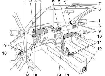
Part 1
OPERATION OF INSTRUMENTS AND CONTROLS—Chapter 1−4
Lights, Wipers and DefoggerD Headlights and turn signals D Emergency flashers D Instrument panel light control D Interior light D Ignition switch light D Personal light D Windshield wipers and washer D Rear window and outside
rear view mirror defoggers
78
Headlights and turn signals
tail,
license plate,
HEADLIGHTS To turn on the following lights: Twist the headlight/turn signal lever knob. Position 1—Parking, side marker and instrument panel lights Position 2—Headlights and all of above The lights automatically turn off when the driver’s door is opened with the ignition turned off. To turn them on again, turn the key to the ”ON” position or actuate the headlight switch. If you are going to park for over one week, make sure the head- light switch is off.
the
NOTICE
To prevent the battery from being dis- charged, do not leave the lights on for a long period when the engine is not running.
Daytime running light system (Canada only) The headlights turn on at reduced intensi- ty when the parking brake is released with the engine started, even with light switch in the ”OFF” position. They will not go off until the ignition switch is turned off. To turn on the other exterior lights and instrument panel lights, twist the knob to the position 1. Twist the knob to the position 2 to turn to full intensity for driving at night.
the
Emergency flashers
High−Low beams—For high beams, turn the headlights on and push the lever away from you (position 1). Pull the lever to- ward you (position 2) for low beams. The headlight high beam light indicator (blue light) on the instrument panel will tell you that the high beams are on. Flashing the high beam headlights (position 3)—Pull the way back. The high beam headlights turn off when you release the lever. You can flash the high beam headlights with the knob turned to ”OFF”.
the lever all
TURN SIGNALS To signal a turn, push the headlight/ turn signal lever up or down to position 1. The key must be in the ”ON” position. The lever automatically returns after you make a turn, but you may have to return it by hand after you change lanes. To signal a lane change, move the lever up or down to the pressure point (position 2) and hold it. If the turn signal indicator lights (green lights) on the instrument panel flash faster than normal, a front or rear turn signal bulb is burned out.
flashers,
turn on
the emergency
To push the switch. All the turn signal lights will flash. To turn them off, push the switch once again. Turn on the emergency flashers to warn other drivers if your vehicle must be stopped where it might be a traffic hazard. Always pull as far off the road as pos- sible. The turn signal light switch will not work when the emergency flashers are operat- ing.
79
Instrument panel light control
Interior light
NOTICE
To prevent the battery from being dis- charged, do not leave the switch on longer than necessary when the en- gine is not running.
To adjust the brightness of the instru- ment panel lights, turn the knob.
80
To turn on the interior light, slide the switch. The interior light switch has the following positions: ”ON”—Keeps the light on all the time. ”OFF”—Turns the light off. ”DOOR”—Turns the light on when any of the door is opened. The light goes off when all the doors are closed. On some models, for some time after all of the doors are closed.
light remains on
the
Ignition switch light
Personal light
Windshield wipers and washer
For easy access to the ignition switch, the ignition switch light comes on when any of the doors are opened. The light remains on for a certain time after all the doors are closed. Vehicles with power door lock system —When all the doors are locked or the ignition switch is turned to ”ACC”, ”ON” after all the doors are closed, the light fades out.
To turn on the personal light, push the switch. To turn it off, push the switch once again.
To turn on the windshield wipers, move the lever to the desired setting. The key must be in the ”ON” position.
Lever position
Speed setting
Position 1
Position 2
Position 3Intermittent
Slow Fast
interval adjuster: The
With ”INT TIME” band lets you adjust the wiping time inter- val when the wiper lever is in the intermit- tent position (position 1). Twist the band upward time between sweeps, and downward to decrease it.
increase
the
to
81
To squirt washer fluid, pull the lever toward you. If the windshield wipers are off, they will operate a couple of times after the washer squirts. For instructions on adding washer fluid, see ”Adding washer fluid” in Chapter 7−3. In freezing weather, warm the windshield with the defroster before using the washer. This will help prevent fluid from freezing on your windshield, which can block your vision.
the washer
NOTICE
Do not operate the wipers if the wind- shield the glass.
It may scratch
is dry.
82
Rear window and outside rear view mirror defoggers
To defog or defrost the rear window, push the switch. The key must be in the ”ON” position. The thin heater wires on the inside of the rear window will quickly clear the sur- faces. An indicator light will illuminate to indicate the defogger is operating. in the On some models, heater panels outside rear view mirrors will also quickly clear the surfaces. Push the switch once again to turn the defogger off. The system will automatically shut off af- ter the defogger has operated about 15
minutes.CAUTION
Since the mirror surfaces can get hot keep your hands off them when the switch is on.
turn
the defoggers off Make sure you when the surfaces are clear. Leaving the defoggers on for a long time could cause the battery to discharge, especially during stop−and−go driving. The defoggers are not designed for drying rain water or for melting snow. If the outside rear view mirrors are heavi- ly coated with ice, use a spray de−icer before operating the switch.
NOTICE
When cleaning the inside of the rear window, be careful not to scratch or damage the heater wires.
83
On inclines or curves, due to the move- ment of fuel in the tank, the fuel gauge needle may fluctuate or the low fuel level warning light may come on earlier than usual. If the fuel tank is completely empty, the malfunction indicator lamp comes on. Fill the fuel tank immediately. The indicator lamp goes off after driving several times. If the indicator lamp does not go off, contact your Toyota dealer as soon as possible.
Part 1
OPERATION OF INSTRUMENTS AND CONTROLS—Chapter 1−5
Gauges, Meters and Service reminder indicatorsD Fuel gauge D Engine coolant temperature
gauge
D Tachometer D Odometer and two trip meters D Service reminder indicators and
warning buzzers
84
Fuel gauge
Low fuel level warning light
the
The gauge works when ignition switch is on and indicates the approxi- mate quantity of fuel remaining in the tank. Nearly full—Needle at ”F” Nearly empty—Needle at ”E” It is a good idea to keep the tank over 1/4 full. This fuel gauge has a non−return type needle which remains at the last indicated position when the ignition switch is turned off. If the fuel level approaches ”E” or the low fuel level warning light comes on, fill the fuel tank as soon as possible.
Engine coolant temperature gauge
Tachometer
D Idling for a long period with the air conditioning on in stop−and−go traffic.
D Towing a trailer.
NOTICE
z Do not remove the thermostat
in the engine cooling system as this may cause the engine to overheat. The thermostat is designed to con- trol the flow of coolant to keep the temperature of the engine within the specified operating range.
z Do not continue driving with an overheated engine. See ”If your ve- hicle overheats” in Part 4.
The gauge indicates the engine coolant temperature when the ignition switch is on. The engine operating temperature will vary with changes in weather and engine load. If the needle moves into the red zone, your engine is too hot. If your vehicle overheats, stop your vehicle and allow the engine to cool. Your vehicle may overheat during severe operating conditions, such as: D Driving up a long hill on a hot day. D Reducing speed or stopping after high
speed driving.
The tachometer indicates engine speed in thousands of rpm ( revolutions per minute). Use it while driving to select correct shift points and to prevent en- gine lugging and overrevving. Driving with the engine running too fast causes excessive engine wear and poor fuel economy. Remember, in most cases the slower the engine speed, the greater the fuel economy.
NOTICE
Do not let the indicator needle get into the red zone. This may cause severe engine damage.
85
3. Trip meter reset knob—It can reset the to zero, and also
trip meters
two change the meter display. To change the meter display, quickly push and release the knob. The meter display changes in the order from the odometer to trip meter A to trip meter then back B, the odometer each time you push. To reset the trip meter A to zero, dis- play the meter A reading, then push and hold the knob until the meter is set to zero. The same process can be applied for resetting the trip meter B.
to
Service and warning buzzers
reminder
indicators
If the indicator or buzzer comes on...
Do this.
(a)
(type A)
If parking brake is off, stop and check.
(type B)
(b)
Fasten seat belts.
(Indicator and buzzer)
(c)
(d)
Stop and check.
Take vehicle to Toyota dealer.
(e)
Low fuel level warning light
Fill up tank.
Odometer and two trip meters
This meter displays the odometer and two trip meters. 1. Odometer—It shows the total distance
the vehicle has been driven.
2. Two trip meters—They show two differ- ent distances independently driven since the last time each trip meter was set to zero. You can use one trip meter to calculate the to measure the distance on each trip. All trip meter data is cancelled if the elec- trical power source is disconnected.
fuel economy and
the other
86
If the indicator or buzzer comes on...
Do this.
If the indicator or buzzer comes on...
Do this.
(f)
(g)
(h)
(i)
(j)
Stop and check.
Take vehicle to Toyota dealer immediately.
(k)
(l)
Add washer fluid.
Take vehicle to Toyota dealer.
(m)
Key reminder buzzer
Remove key.
(type A)
(type B)
Close all doors.
Replace bulb.
Take vehicle to Toyota dealer immediately.
(a) Brake System Warning Light This light has the following functions: Parking brake reminder If this light is on, make sure the parking brake is fully released. The light should go off. Low brake fluid level warning If this light comes on and stays on while you are driving, slow down and pull off the road. Then stop the vehicle carefully. Remember that stopping distance and ped- al effort may be increased. There may be a problem somewhere in the brake sys- tem. Check the see− through reservoir. To make sure the parking brake has not caused to come on, check to see that the parking brake is fully released. If the brake fluid level is low... At a safe place, test your brakes by start- ing and stopping. D If you judge that the brakes still work to your
adequately, drive cautiously nearest dealer or shop for repairs.
the fluid level of
the warning
light
D If the brakes are not working, have the vehicle towed in for repairs. (For tow- ing information, see Part 4.)
87
CAUTION
NOTICE
It is dangerous to continue driving normally when the brake fluid level is low.
If the brake fluid level is correct... Have the warning system checked by your Toyota dealer. (b) Seat Belt Reminder Light and Buzz-
er
fastens
the driver
the reminder
Once the ignition key is turned to ”ON” or ”START”, light and buzzer come on if the driver’s seat belt is not fastened. Unless the belt, the light stays on and the buzzer stops after about 4 to 8 seconds. (c) Discharge Warning Light This light warns that the battery is being discharged. If it comes on while you are driving, there is a problem somewhere in the charging system. The engine ignition will continue to oper- the battery ate, however, until is dis- charged. Turn off the air conditioning, blower, radio, etc., and drive directly to the nearest Toyota dealer or repair shop.
88
Do not continue driving if the engine drive belt is broken or loose.
in
following
lamp comes on
(d) Malfunction Indicator Lamp This the cases. a. The fuel tank is completely empty. (See ”Fuel gauge” in Chapter 1−5 for instruc- tions.) b. The fuel tank cap is not tightened se- curely. (See ”Fuel tank cap” in Chapter 1−2 for instructions.) c. There is a problem somewhere in your engine or automatic transmission electrical system. If it comes on while you are driving in case c, have your vehicle checked/re- paired by your Toyota dealer as soon as possible. (e) Low Fuel Level Warning Light This light comes on when the fuel level in the tank becomes nearly empty. Fill up the tank as soon as possible. On inclines or curves, due to the move- ment of fuel in the tank, the low fuel level warning light may come on earlier than usual.
(f) Low Oil Pressure Warning Light This light warns that the engine oil pres- sure is too low. If it flickers or stays on while you are driving, pull off the road to a safe place and stop the engine immediately. Call a Toyota dealer or qualified repair shop for assistance. The flicker when the engine is idling or it may come on briefly after a hard stop. There is no cause for concern if it then goes out when the engine is accelerated slightly. The light may come on when the oil level is extremely is not designed to indicate low oil level, and the oil level must be checked using the level dipstick.
light may occasionally
low. It
NOTICE
Do not drive the warning light on—even for one block. It may ruin the engine.
the vehicle with
(g) ”ABS” Warning Light This light warns that there is a problem somewhere in your anti−lock brake sys- tem.
If the light comes on while you are driv- ing, have your vehicle checked by your Toyota dealer as soon as possible. The light will come on when the ignition key is turned to the ”ON” position. After about 3 seconds, the light will go off. When the ”ABS” warning light is on (and the brake system warning light is off), the brake system operates conventionally but anti−lock brake system is not assisting brake performance so that the wheels can lock−up during sudden braking or braking on slippery road surfaces. (h) Open Door Warning Light This light remains on until all the doors and back door are completely closed. (i) Rear Light Failure Warning Light If this light comes on when the headlight switch is turned on (at the first or second clickstop), it indicates that one or more of the tail lights are burned out. If it comes on when the brake pedal is depressed, one or more stop lights are burned out. Have defective bulbs replaced as soon as possible.
(j) SRS Airbag Warning Light This light will come on when the igni- tion key is turned to the ”ACC” or ”ON” position. After about 6 seconds, the light will go off. This means the systems of the airbag and front seat belt pretensioner are operating properly. The warning light system monitors the air- bag sensor assembly, seat belt pretension- er assembly, inflators, warning light, inter- connecting wiring and power sources. If either of the following conditions occurs, this indicates a malfunction somewhere in the parts monitored by the warning light system. Contact your Toyota dealer as soon as possible to service the vehicle. D The light does not come on when the ignition key is turned to the ”ACC” or ”ON” position or remains on.
D The light comes on or flashes while
driving.
(k) Low Windshield Washer Fluid Level
Warning Light
The light warns that the windshield washer fluid level is too low. Add washer fluid at your earliest opportunity. (For instructions, see ”Adding washer fluid” in Chapter 7−3.)
(l) ”TRAC OFF” Indicator/Warning Light This light comes on when the ignition key is turned to ”ON”, and will go off after 3
seconds. This means that the system is operating properly. If one of the following conditions occurs, this indicates a malfunction somewhere in the parts monitored by the warning light system. Contact your Toyota dealer as soon as possible to service the vehicle. D The light remains on more than 3 se- conds after the ignition switch is turned on.D The light comes on while driving even is not
”TRAC OFF” switch
if the pushed.
D The light flashes. (m) Key Reminder Buzzer This buzzer reminds you to remove the key when you open the driver’s door with the ignition key in the ”ACC” or ”LOCK” position.
89
CHECKING SERVICE REMINDER INDICA- TORS (except the low fuel level warning light and low windshield washer fluid level warning light) 1. Apply the parking brake. 2. Open one of the doors.
The open door warning come on.
light should
3. Close the door.
The open door warning light should go off.
4. Turn the ignition key to ”ACC”.
The SRS airbag warning light should come on. It goes off after about 6 se- conds.
5. Turn the ignition key to ”ON”, but do
not start the engine.
All the service reminder indicators except the open door warning light, SRS airbag warning light and low windshield washer fluid level warning light should come on. The ”ABS” warning light goes off after about 3 seconds. If any service reminder indicator or warn- ing buzzer does not function as described above, either the bulb is burned out or the circuit it checked by your Toyota dealer as soon as possible.
repair. Have
in need of
is
90
91
Part 1
OPERATION OF INSTRUMENTS AND CONTROLS—Chapter 1−6
Ignition switch, Transmission and Parking brakeD Ignition switch with steering lock D Automatic transmission D Manual transmission D Parking brake D Cruise control
92
Ignition switch with steering lock
”START”—Starter motor on. The key will return to the ”ON” position when released. For starting tips, see Part 3. ”ON”—Engine on and all accessories on. This is the normal driving position. ”ACC”—Accessories such as the radio operate, but the engine is off. the ”ACC” or If you ”LOCK” position and open the driver’s door, a buzzer will remind you to remove the key. ”LOCK”—Engine is off and the steering wheel is locked. The key can be re- moved only at this position.
the key
leave
in
You must push in the key to turn the key from ”ACC” to the ”LOCK” position. On vehicles with an automatic transmission, the selector lever must be put in the ”P” position before pushing the key. Vehicles with engine immobiliser system— Once you remove the key, the engine im- mobiliser system is automatically set. (See ”Engine in Chapter 1−2.) When starting the engine, the key may seem stuck at the ”LOCK” position. To free it, first be sure the key is pushed all the way in, and then rock the steering wheel slightly while turning the key gently.
immobiliser system”
CAUTION
For manual transmission: Never remove the key when the ve- hicle is moving, as this will lock the steering wheel and result in loss of steering control.
NOTICE
leave the key
in the ”ON” Do not position if the engine is not running. The battery will discharge and the ignition could be damaged.
93
Automatic transmission
Lock release button To prevent misshifting
Parking, engine starting and key removable postion
Reverse position
Neutral position
Normal driving position Position for engine braking Position for stronger engine braking than that in ”2” position
With the brake pedal depressed, shift while holding the lock release button in. (The ignition switch must be in ”ON” position.)
Shift while holding the lock release button in
Shift normally
Overdrive switch For selecting either a three-speed or four-speed transmission
ON position (Shifting into overdrive possible)
OFF position (Shifting into overdrive not possible)
”O/D OFF” indicator light shows the overdrive switch is in OFF position
Vehicles with cruise control⎯When the cruise control is being used, even if you downshift the transmission by turning off the overdrive switch, engine braking will not be applied because the cruise control is not cancelled. For ways to decrease the vehicle speed, see ”Cruise control” in this chapter. 94
Your automatic transmission has a shift lock system to minimize the possibility of incorrect operation. This means you can only shift out of ”P” position when the brake pedal is depressed (with the ignition switch in ”ON” position and the lock re- lease button depressed). (a) Normal driving 1. Start the engine as instructed in ”How in Part 3. The
to start transmission must be in ”P” or ”N”.
the engine”
2. With your foot holding down the brake
pedal, shift the selector lever to ”D”.
In ”D” position, the automatic transmission system will select the most suitable gear for the running conditions such as normal cruising, hill climbing, hard towing, etc. Always turn the overdrive switch on for better fuel economy and quieter driving. If the engine coolant temperature is low, the transmission will not shift into overdrive gear even with the overdrive switch on.
CAUTION
Never put your foot on the accelera- tor pedal while shifting.
3. Release the parking brake and brake the accelerator pedal
pedal. Depress slowly for smooth starting.
(b) Using engine braking To use engine braking, you can downshift the transmission as follows: D Turn off the overdrive switch. The ”O/D OFF” indicator light will come on and the transmission will downshift to the third gear.
D Shift into the ”2” position. The trans- the second mission will downshift the vehicle speed drops gear when down lower the following to or speed, and more powerful engine brak- ing will be obtained.
than
to
5S−FE engine...... 106 km/h (65 mph) 1MZ−FE engine.... 119 km/h (73 mph) D Shift into the ”L” position. The trans- mission will downshift to the first gear When the vehicle speed drops down to or lower than the following speed, and maximum engine braking will be ap- plied.
5S−FE engine........ 46 km/h (28 mph) 1MZ−FE engine..... 56 km/h (34 mph)
Vehicles with cruise control⎯When the cruise control is being used, even if you downshift the transmission by turning off the overdrive switch, engine braking is not applied because the cruise control is not cancelled. For ways to decrease the vehicle speed, see ”Cruise control” in this chapter.
CAUTION
Be careful when downshifting on a slippery shifting could cause the vehicle to spin or skid.
surface. Abrupt
(c) Using ”2” and ”L” positions The ”2” and ”L” positions are used for strong engine braking as described pre- viously. With the selector lever in ”2” or ”L”, you can start the vehicle in motion as with the lever in ”D”. With the selector lever in ”2”, the vehicle will start in the first gear and automatical- ly shift to the second gear. With the selector lever in ”L”, the trans- mission is engaged in the first gear.
95
NOTICE
z Be careful not to overrev the en- gine. Watch the tachometer to keep engine rpm from going into the red zone. The approximate maximum al- lowable speed for each position is given below for your reference:
”2”.................125 km/h (77 mph) ”L”.................. 69 km/h (42 mph) z Do not continue hill climbing or hard towing for a long time in the ”2” or ”L” position. This may cause severe automatic transmission dam- age from overheating. To prevent such damage, ”D” position should be used in hill climbing or hard towing.
(d) Backing up 1. Bring the vehicle to a complete stop. 2. With the brake pedal held down with your foot, shift the selector lever to the ”R” position.
NOTICE
Never shift into reverse while the ve- hicle is moving.
96
(e) Parking 1. Bring the vehicle to a complete stop. 2. Pull the parking brake lever up fully to
securely apply the parking brake.
3. With
the brake pedal pressed down, shift the selector lever to the ”P” posi- tion.
CAUTION
is moving, never While the vehicle lever attempt to move the selector into ”P” position under any circum- stances. Serious mechanical damage and loss of vehicle control may re- sult.
(f) Good driving practice D If
the
transmission is repeatedly up- shifted and downshifted between the third gear and overdrive when climbing a gentle slope, the overdrive switch should be turned off. Be sure to turn the switch on immediately afterward.
D When towing a trailer, in order to main- tain engine braking efficiency, do not use overdrive.
CAUTION
Always keep your foot on the brake pedal while stopped with the engine running. This prevents the vehicle from creeping.
NOTICE
Do not hold the vehicle on an up- grade with the accelerator pedal. It can cause the transmission to over- heat. Always use the brake pedal or parking brake.
(g) Rocking your vehicle if stuck
CAUTION
To rock your vehicle if it becomes stuck in snow, mud, sand, etc., first check that there are no objects or people around the vehicle. During the rocking operation the vehicle may suddenly move forward or backward as it becomes unstuck, causing injury or damage to nearby people or ob- jects.
NOTICE
Manual transmission
to
the
If you rock your vehicle, observe the following precautions to prevent dam- age transmission and other parts. z Do not depress the accelerator ped- al while shifting the selector lever