- 2006 Toyota Camry Owners Manuals
- Toyota Camry Owners Manuals
- 1998 Toyota Camry Owners Manuals
- Toyota Camry Owners Manuals
- 2015 Toyota Camry Owners Manuals
- Toyota Camry Owners Manuals
- 2001 Toyota Camry Owners Manuals
- Toyota Camry Owners Manuals
- 2010 Toyota Camry Owners Manuals
- Toyota Camry Owners Manuals
- 2004 Toyota Camry Owners Manuals
- Toyota Camry Owners Manuals
- 2005 Toyota Camry Owners Manuals
- Toyota Camry Owners Manuals
- 1997 Toyota Camry Owners Manuals
- Toyota Camry Owners Manuals
- 2000 Toyota Camry Owners Manuals
- Toyota Camry Owners Manuals
- 2002 Toyota Camry Owners Manuals
- Toyota Camry Owners Manuals
- 2012 Toyota Camry Owners Manuals
- Toyota Camry Owners Manuals
- 1996 Toyota Camry Owners Manuals
- Toyota Camry Owners Manuals
- 2003 Toyota Camry Owners Manuals
- Toyota Camry Owners Manuals
- 2009 Toyota Camry Owners Manuals
- Toyota Camry Owners Manuals
- 2008 Toyota Camry Owners Manuals
- Toyota Camry Owners Manuals
- Download PDF Manual
-
9. Windshield washer fluid tank
201
1. Power steering fluid reservoir
2. Engine coolant reservoir
3. Engine oil level dipstick
4. Engine oil filler cap
5. Brake fluid reservoir
6. Fuse blocks
7. Battery
8. Electric cooling fans
9. Windshield washer fluid tank
"1MZ−FE engine
202
Fuse locations
Spare fuses
Canada
California
203
Do−it−yourself service precautions If you perform maintenance by yourself, be sure to follow the correct procedure given in this part. You should be aware that improper or in- complete servicing may result in operating problems. Performing do−it−yourself maintenance during the warranty period may affect your warranty coverage. Read the separate Toyota Warranty statement for details and suggestions. This part gives instructions only for those items that are relatively easy for an owner to perform. As explained in Part 6, there are still a number of items that must be done by a qualified technician with special tools. For information on tools and parts for do− it−yourself maintenance, see ”Parts and tools”. Utmost care should be taken when work- ing on your vehicle to prevent accidental injury. Here are a few precautions that you should be especially careful to ob- serve:
Type A
Type B
204
CAUTION
D When the engine is running, keep hands, clothing, and tools away from the moving fan and engine drive rings, watches, and ties is advisable.)
(Removing
belts.
D Right after driving,
the engine compartment—the engine, radiator, exhaust manifold and spark plug boots, etc. —will be hot. So be careful not them. Oil, fluids and spark plugs may also be hot.
touch
to
D If the engine is hot, do not remove the radiator cap or loosen the drain plugs to prevent burning yourself. D Do not smoke, cause sparks or al- low open flames around fuel or the battery. Their fumes are flammable. D Be extremely cautious when work- ing on the battery. It contains poi- sonous and corrosive sulfuric acid. D Do not get under your vehicle with just the body jack supporting it. Al- ways use automotive jack stands or other solid supports.
D Be sure that the ignition is off if you work near the electric cooling fans or radiator grille. With the ignition on, the electric cooling fans will automatically start to run if the engine coolant temperature is high and/or the air conditioning is on.
D Use eye protection whenever you work on or under your vehicle where you may be exposed to flying or falling material, fluid spray, etc. D Used engine oil contains potentially harmful contaminants which may cause skin disorders such as in- flammation or skin cancer, so care should be taken to avoid prolonged and repeated contact with it. To re- move used engine oil from your skin, wash thoroughly with soap and water.
D Do not
leave used oil within the
reach of children.
D Dispose of used oil and filter only in a safe and acceptable manner. Do not dispose of used oil and fil- ter in household trash, in sewers or onto the ground. Call your dealer or a service station information concerning recycling or disposal.
for
NOTICE
z Remember that battery and ignition cables carry high currents or volt- ages. Be careful of accidentally causing a short circuit.
z Add only demineralized or distilled water to fill the radiator. And if you spill some of the coolant, be sure to wash off with water to prevent it from damaging the parts or paint.
z Do not allow dirt or anything else to fall through the spark plugholes. z Use only spark plugs of the speci- fied type. Using other types will cause engine damage, loss of per- formance or radio noise.
z Do not reuse platinum−tipped spark
plugs by cleaning or regapping.
205
z Do not overfill automatic transmis- transmission
fluid, or
the
sion could be damaged.
z Do not drive with the air cleaner filter removed, or excessive engine wear could result. Also backfiring could cause a fire in the engine compartment.
z Be careful not to scratch the glass
surface with the wiper frame.
z When closing
the engine hood, check to see that you have not for- gotten any tools, rags, etc.
206
Parts and tools Here is a list of parts and tools you will need on performing do−it−yourself mainte- nance. Remember all Toyota parts are de- signed in metric sizes, so your tools must be metric. Checking the engine oil level Parts (if level is low): D Engine oil API grade SH, ”Energy−Con- serving II” or SJ, ”Energy−Conserving” multigrade or ILSAC multigrade having viscosity proper for your climate
Tools: D Rag or paper towel D Funnel (only for adding oil) Checking the engine coolant level Parts (if level is low): D Ethylene−glycol antifreeze D Demineralized or distilled water Tools: D Funnel (only for adding coolant) Checking brake fluid Parts (if level is low): D SAE J1703 or FMVSS No. 116 DOT 3
brake fluid
Tools: D Rag or paper towel D Funnel (only for adding fluid)
Checking power steering fluid Parts (if level is low): D Automatic
transmission
DEXRON®II or III
Tools: D Rag or paper towel D Funnel (only for adding fluid) Checking battery condition Tools: D Warm water D Baking soda D Grease D Conventional wrench
(for
clamp bolts)
fluid
terminal
Checking and replacing fuses Parts (if replacement is necessary): D Genuine Toyota fuse or equivalent with
same amperage rating as original
Adding washer fluid Parts: D Water D Washer fluid containing antifreeze (for
winter use)
Tools: D Funnel
Replacing light bulbs Parts: D Bulb with same number and wattage rating as original (See charts in ”Re- placing light bulbs” in Chapter 7−3.)
Tools: D Screwdriver D Flat−bladed screwdriver
207
Part 7
DO−IT−YOURSELF MAINTENANCE—Chapter 7−2
Engine and ChassisD Checking the engine oil level D Checking the engine coolant
level
D Checking brake fluid D Checking power steering fluid D Checking tire pressure D Checking and replacing tires D Rotating tires D Installing snow tires and chains D Replacing wheels D Aluminum wheel precautions
208
Checking the engine oil level
Low level
Full level
CAUTION
Type A
Type B
Add oil
O.K.
Too full
With the engine at operating tempera- ture and turned off, check the oil level on the dipstick. 1. To get a
the vehicle should be on a level spot. After turning off the engine, wait a few minutes for the oil to drain back into the bottom of the engine.
reading,
true
2. Pull out the dipstick, and wipe it clean
with a rag.
3. Reinsert the dipstick—push it in as far as it will go, or the reading will not be correct.
4. Pull the dipstick out and look at the oil
level on the end.
Be careful not to touch the hot ex- haust manifold.
If the oil level is below or only slightly above the low level line, add engine oil of the same type as already in the en- gine. Remove the oil filler cap and add engine oil in small quantities at a time, checking the dipstick. The approximate quantity of oil needed to fill between the low level and the full level on the dipstick is indicated below for ref- erence. When the level reaches within the correct range, install the filler cap hand−tight. Oil quantity, L (qt., lmp. qt.):
5S−FE engine 1MZ−FE engine
0.7 (0.7, 0.6) 1.5 (1.6, 1.3)
NOTICE
z Avoid overfilling, or
the engine
could be damaged.
z Check the oil level on the dipstick
once again after adding the oil.
Engine oil selection Use API grade SH, ”Energy−Conserving II” or SJ, ”Energy−Conserving” multigrade engine oil or ILSAC multigrade engine oil. Recommended viscosity (SAE):
API service symbol
for good
SAE 5W−30 is the best choice for your vehicle, fuel economy, and good starting in cold weather. If you use SAE 10W−30 engine oil in extremely low temperatures, the engine may become difficult to start, so SAE 5W−30engine oil is recommended.
Oil identification marks Either or both API registered marks are added to some oil containers to help you select the oil you should use. The API Service Symbol is located any- where on the outside of the container. The top portion of the label shows the oil quality by API (American Petroleum Insti- tute) designations such as SJ. The center portion of the label shows the SAE viscos- ity grade such as SAE 5W−30. ”Energy− Conserving” shown in the lower portion, indicates that the oil has fuel−saving ca- pabilities. The ILSAC (International Lubricant Stan- dardization and Approval Committee) Certi- fication Mark is displayed on the front of the container.
ILSAC certification mark
209
Checking the engine coolant level Look at the see−through coolant reser- voir when the engine is cold. The cool- ant level is satisfactory if it is between the ”FULL” and ”LOW” lines on the reservoir. If the level is low, add ethyl- ene−glycol type coolant. The coolant level in the reservoir will vary with engine temperature. However, if the level is on or below the ”LOW” line, add coolant. Bring the level up to the ”FULL” line. Use only ethylene−glycol See information in the next column. If the coolant level drops within a short time after replenishing, there may be a leak the radiator, hoses, engine coolant filler cap, radiator cap and drain cock and water pump. If you can find no leak, have your Toyota dealer test the cap pressure and check for leaks in the cooling system.
the system. Visually check
type coolant.
in
CAUTION
To prevent burning yourself, do not remove the radiator cap when the en- gine is hot.
210
Coolant type selection Your coolant must contain ethylene−glycol antifreeze. In addition to preventing freez- ing and subsequent damage to the engine, this will also prevent corrosion. Further supplemental inhibitors or additives are neither needed nor recommended. Read the antifreeze container for informa- tion on the manufacturer’s directions for how much to mix with water. The total capacity of the cooling system is given in Part 8. We recommend 50 % solution be used for your Toyota, or a sufficient quantity to provide about —35_C (—31_F).
freeze protection. Follow
protection
to
NOTICE
Do not use alcohol type antifreeze or plain water alone.
Checking brake fluid
reservoir. The
To check the fluid level, simply look at the see−through level should be between the ”MAX” and ”MIN” lines on the reservoir. It is normal for the brake fluid level to go down slightly as the brake pads wear. So be sure to keep the reservoir filled. If the reservoir needs frequent refilling, it may indicate a serious mechanical prob- lem. If the level is low, add SAE J1703 or FMVSS No. 116 DOT 3 brake fluid to the brake reservoir. Remove and replace the reservoir cover by hand.
Use only newly opened brake fluid. Once opened, brake fluid absorbs moisture from the air, and excess moisture can cause a dangerous loss of braking.
CAUTION
Take care when filling the reservoir because brake fluid can harm your eyes and damage painted surfaces. If fluid gets in your eyes, flush your eyes with clean water.
NOTICE
If you spill some of the fluid, be sure to wash it off with water to prevent it from damaging the parts or paint.
Checking power steering fluid
Open
If cold O.K.
If cold add
Close
If hot O.K.
If hot add
III.
Check the fluid level through the reser- voir. If necessary, add automatic trans- mission fluid DEXRONrII or If the vehicle has been driven around 80
km/h (50 mph) for 20 minutes (a little more in frigid temperatures), the fluid is hot (60_C—80_C or 140_F—175_F). You may also check the level when the fluid is temperature, 10_C—30_C or 50_F—85_F) if the engine has not been run for about five hours.(about
room
cold
Clean all dirt from outside of the reservoir tank and look at the fluid level. If the fluid is cold, the level should be in the ”COLD” range. Similarly, if it is hot, the fluid level should be in the ”HOT” range. If the level is at the low side of either range, add automatic fluid DEXRONrII or III to bring the level within the range. To remove the filler cap, turn it counter- clockwise and lift up. To reinstall it, turn it clockwise. After filler cap,visually check the steering box case, vane pump and hose connections for leaks or damage.
transmission
replacing
the
CAUTION
The reservoir tank may be hot so be careful not to burn yourself.
NOTICE
Avoid overfilling, or the power steer- ing could be damaged.
211
Checking tire pressure
Keep your tire pressures at the proper level. The recommended cold tire pressures, tire size and the vehicle capacity weight are given in Part 8. They are also on the tire pressure label as shown. You should check the tire pressures every two weeks, or at least once a month. And don’t forget the spare! Incorrect tire pressure can reduce tire life and make your vehicle less safe to drive.
212
the
results
tire pressure
tire pressure
is excessively
Low in excessive wear, poor handling, reduced fuel econo- my, and the possibility of blowouts from overheated tires. Also, low tire pressure can cause poor sealing of the tire bead. If low, there is the possibility of wheel deforma- tion and/or tire separation. High tire pressure produces a harsh ride, handling problems,excessive wear at the center of the tire tread, and a greater possibility of tire damage from road haz- ards. If a tire frequently needs refilling, have it checked by your Toyota dealer. The following instructions for checking tire pressure should be observed: D The pressure should be checked only when the tires are cold. If your ve- hicle has been parked for at least 3
hours and has not been driven for more than 1.5 km or 1 mile since, you will get an accurate cold tire pressure reading.D Always use a tire pressure gauge. The appearance of a tire can be mis- leading. Besides, that are even just a few pounds off can degrade handling and ride.
tire pressures
D Take special care when adding air to the compact spare tire. The smaller tire size can gain pressure very quick- ly. Add compressed air in small quanti- ties and check the pressure often until it reaches the specified pressure.
D Do not bleed or reduce tire pressure after driving. It is normal for the tire pressure to be higher after driving.
D Never exceed
the vehicle capacity weight. The passenger and luggage weight should be located so that the vehicle is balanced.
D Be sure to reinstall the tire inflation valve caps. Without the valve caps, dirt or moisture could get into the valve core and cause air leakage. If the caps have been lost, have new ones put on as soon as possible.
Checking and replacing tires
Tread wear indicator
CHECKING YOUR TIRES Check the tires tread for the tread wear indicators. If the indicators show, re- place the tires. The tires on your Toyota have built−in tread wear indicators to help you know when the tires need replacement. When the tread depth wears to 1.6 mm (0.06
in.) or less, the indicators will appear. If you can see the indicators in two or more adjacent grooves, the tire should be re- placed. The lower the tread, the higher the risk of skidding. The effectiveness of snow tires is lost if the tread wears down below 4 mm (0.16 in.).Check the tires regularly for damage such as cuts, splits and cracks. If any damage is found, consult with a techni- cian and have the tire repaired or re- placed. Even if the damage does not appear seri- ous, a qualified technician should examine the damage. Objects which have pene- trated the tire may have caused internal damage. Any tires which are over six years old must be checked by a qualified techni- cian even if damage is not obvious. Tires deteriorate with age even have never or seldom been used. This applies also to the spare tire and tires stored for future use. REPLACING YOUR TIRES When replacing a tire, use only the same size and construction as original- ly installed and with the same or great- er load capacity. Using any other size or type of tire may seriously affect handling, ride, speedome- ter/odometer calibration, ground clearance, and clearance between the body and tires or snow chains.
they
if
CAUTION
D Do not mix radial, bias belted, or bias−ply tires on your vehicle. It can cause dangerous handling char- acteristics, resulting in loss of con- trol.
D Do not use tires or wheels other recom-
the manufacturer’s
than mended size.
tire
Toyota recommends all four tires, or at least both of the front or rear tires be replaced at a time as a set. See ”If you have a flat tire” in Part 4 for tire change procedure. When a is replaced, should always be balanced. An unbalanced wheel may affect vehicle handling and tire life. Wheels can get out of balance with regular use and should therefore be balanced occasionally. When replacing a tubeless tire, the air valve should also be replaced with a new one.
the wheel
213
Rotating tires
CAUTION
Do not include a compact spare tire when rotating the tires. It is designed for temporary use only.
To equalize the wear and help extend tire life, Toyota recommends that you rotate your tires approximately every 12000 km (7500 miles). However, the most appropriate timing for tire rotation may vary according to your driving hab- its and road surface conditions. See ”If you have a flat tire” in Part 4 for tire change procedure. When for uneven wear and damage. Abnormal wear is usu- ally caused by incorrect tire pressure, im- proper wheel alignment, out−of−balance wheels, or severe braking.
tires, check
rotating
214
Installing snow tires and chains WHEN TO USE SNOW TIRES OR CHAINS Snow tires or chains are recommended when driving on snow or ice. On wet or dry roads, conventional tires provide better traction than snow tires. SNOW TIRE SELECTION If you need snow tires, select the same size, construction and load capacity as the original tires on your Toyota. Do not use tires other than those men- tioned above. Do not install studded tires without first checking local regulations for possible restrictions. SNOW TIRE INSTALLATION Snow tires should be installed on all wheels. Installing snow tires on the front wheels only can lead to an excessive difference in road grip capability between the front and rear tires which could cause loss of vehicle control. When storing removed tires you should store them in a cool dry place. Mark the direction of rotation and be sure to install them in the same direction when replac- ing.
CAUTION
D Do not drive with the snow tires
incorrectly inflated.
D Never drive over 120 km/h (75 mph)
with any type of snow tires.
TIRE CHAIN SELECTION Use the tire chains of correct size and type. Use SAE Class ”S” type radial tire chains except radial cable chains or V−bar type chains. Regulations regarding the use of tire chains vary according to location or type of road, so always check them before installing chains. CHAIN INSTALLATION Install the chains on the front tires as tightly as possible. Do not use tire tires. Retighten chains on chains after km (1/4—1/2 mile). When installing chains on your tires, care- fully follow the instructions of the chain manufacturer.
rear driving
0.5—1.0
the
If wheel covers are used, they will be scratched by the chain band,so remove the covers before putting on the chains.
CAUTION
D Do not exceed 50 km/h (30 mph) or recom- is
the chain manufacturer’s mended speed lower.
limit, whichever
D Drive carefully avoiding bumps, holes, and sharp turns, which may cause the vehicle to bounce.
D Avoid sharp turns or locked−wheel braking, as use of chains may ad- versely affect vehicle handling.
NOTICE
Do not attempt to use a tire chain on the compact spare tire, as it may re- sult in damage to the vehicle as well as the tire.
Replacing wheels WHEN TO REPLACE YOUR WHEELS If you have wheel damage such as bending, cracks or heavy corrosion, the wheel should be replaced. If you fail to replace damaged wheels, the tire may slip off the wheel or they may cause loss of handling control. WHEEL SELECTION When replacing wheels, care should be taken to ensure that the wheels are re- placed by ones with the same load ca- pacity, diameter, rim width, and offset. This must be observed on compact spare tires, too. Correct replacement wheels are available at your Toyota dealer. A wheel of a different size or type may adversely affect handling, wheel and bear- ing life, brake cooling, speedometer/odom- eter calibration, stopping ability, headlight aim, bumper height, vehicle ground clear- ance, and tire or snow chain clearance to the body and chassis.
215
Aluminum wheel precautions D After driving your vehicle the first 1600
km (1000 miles), check that the wheel nuts are tight. repaired, or D If you have changed your the wheel nuts are still tight after driving 1600 km (1000 miles).rotated, tires, check
that
D When using tire chains, be careful not
to damage the aluminum wheels.
D Use only the Toyota wheel nuts and for your aluminum
wrench designed wheels.
D When balancing your wheels, use only Toyota balance weights or equivalent and a plastic or rubber hammer.
D As with any wheel, periodically check your aluminum wheels for damage. If damaged, replace immediately.
Replacement with used wheels is not rec- ommended as they may have been sub- jected to rough treatment or high mileage and could fail without warning. Also, bent wheels which have been straightened may have structural damage and therefore should not be used. Never use an inner tube in a leaking wheel which is designed for a tubeless tire.
216
217
Part 7
DO−IT−YOURSELF MAINTENANCE—Chapter 7−3
Electrical componentsD Checking battery condition D Battery recharging precautions D Checking and replacing fuses D Adding washer fluid D Replacing light bulbs
218
Checking battery condition— —Precautions
CAUTION
BATTERY PRECAUTIONS The battery produces flammable and explosive hydrogen gas. D Do not cause a spark from the bat-
tery with tools.
D Do not smoke or light a match near
the battery.
The electrolyte contains poisonous and corrosive sulfuric acid. D Avoid contact with eyes, skin or
clothes.
D Never ingest electrolyte. D Wear protective safety glasses when
working near the battery.
D Keep children away from the bat-
tery.
EMERGENCY MEASURES D If electrolyte gets
in your eyes, flush your eyes with clean water immediatly and get immediate medi- cal attention. If possible, continue to apply water with a sponge or cloth while en route to the medical office.
D If electrolyte gets on your skin, thoroughly wash the contact area. If you feel pain or burning, get medi- cal attention immediately.
D If electrolyte gets on your clothes, there is a possibility of its soaking through to your skin, so immediate- ly take off the exposed clothing and follow the procedure above, if nec- essary.
D If you happen to swallow electro- lyte, drink a large quantity of water or milk. Follow with milk of magne- sia, beaten raw egg or vegetable oil. Then go immediately for emer- gency help.
—Checking battery exterior
Terminals Ground cable
NOTICE
z Be sure the engine and all accesso- ries are off before performing main- tenance.
z When checking the battery, remove the ground cable from the negative terminal (”—” mark) first and rein- stall it last.
z Be careful not to cause a short cir-
cuit with tools.
z Take care no solution gets into the
battery when washing it.
Hold−down clamp
Check the battery for corroded or loose terminal connections, cracks, or loose hold−down clamp. a.
If the battery is corroded, wash it off with a solution of warm water and bak- ing soda. Coat the outside of the termi- nals with grease to prevent further cor- rosion. If the terminal connections are loose, tighten their clamp nuts—but do not overtighten.
b.
c. Tighten
the hold−down clamp only enough to keep the battery firmly in place. Overtightening may damage the battery case.
—Checking battery fluid
Type A
Green
Dark
Clear or light yellow
Type B
Blue
White
Red
CHECKING BY THE HYDROMETER Check the battery condition by hydrometer color.
the
Hydrometer color
Type A
Type B
GREEN
BLUE
DARK
WHITE
Condition
Good
Charging necessary. Have battery checked by your Toyota dealer.
CLEAR or LIGHT YELLOW
RED
Have battery checked by your Toyota dealer.
219
Battery recharging precautions During recharging, the battery is pro- ducing hydrogen gas. Therefore, before recharging: 1. If recharging with the battery installed on the vehicle, be sure to disconnect the ground cable.
2. Be sure the power switch on the re- charger the charger cables to the battery and when disconnecting them.
is off when connecting
Checking and replacing fuses
Type A
Pull−out tool
Good
Blown
CAUTION
Type B
D Always charge the battery in an un- confined area. Do not charge the battery in a garage or closed room where there is not sufficient ventila- tion.
D Only do a slow charge (5A or less). Charging at a quicker rate is dan- gerous. The battery may explode, causing personal injuries.
NOTICE
Never recharge the battery while the engine is running. Also, be sure all accessories are turned off.
220
Good
Blown
Type C
Good
Blown
If the headlights or other electrical components do not work, check the fuses. If any of the fuses are blown, they must be replaced. See ”Fuse locations” in Chapter 7−1 for locations of the fuses. Turn the ignition switch and inoperative component off. Pull a suspected fuse straight out and check it. Determine which fuse may be causing the problem. The lid of the fuse box shows the name of the circuit for each fuse. See Part 8 of this manual for the functions controlled by each circuit.
can
you
Types A and B fuses can be pulled out by the pull−out tool. The location of the pull−out tool is shown in the illustration. If you are not sure whether the fuse has blown, try replacing the suspected fuse with one that you know is good. If the fuse has blown, push a new fuse into the clip. Only install a fuse with the amperage rat- ing designated on the fuse box lid. If you do not have a spare fuse, in an emergency the ”A/C” ”MIRROR−HEATER”, fuse, which may be dispensable for normal driving, and use it if its amperage rating is the same. If you cannot use one of the same amper- age, use one that is lower,but as close as possible to, the rating. If the amperage is lower than that specified, the fuse might blow out again but this does not indicate anything wrong. Be sure to get the correct fuse as soon as possible and return the substitute to its original clip. It is a good idea to purchase a set of spare fuses and keep them in your ve- hicle for emergencies.
”DOME” or
pull
out
the new
If fuse immediately blows out, there is a problem with the electrical sys- tem. Have your Toyota dealer correct it as soon as possible.
CAUTION
Never use a fuse with a higher am- perage rating, or any other object, in place of a fuse. This may cause ex- tensive damage and possibly a fire.
Adding washer fluid If any washer does not work or low windshield washer fluid level warning light comes on, the washer tank may be empty. Add washer fluid. You may use plain water as washer fluid. in cold areas where tempera- However, tures freezing point, use fluid containing antifreeze. This washer product is available at your Toyota dealer and most auto parts stores. Follow the manufacturer’s directions for how much to mix with water.
range below
NOTICE
Do not use engine antifreeze or any other substitute because it may dam- age your vehicle’s paint.
221
following
illustrations show how
Replacing light bulbs— The to gain access to the bulbs. When replacing a bulb, make sure the ignition switch and light switch are off. Use bulbs with the wattage ratings given in the table.
CAUTION
Halogen bulbs have pressurized gas inside and require special handling. They can burst or shatter if scratched or dropped. Hold a bulb only by its plastic or metal case. Do not touch the glass part of a bulb with bare hands.
NOTICE
Only use a bulb of the listed type.
222
W Type
60/55
A: HB2 halogen bulbs B: Single end bulbs C: Wedge base bulbs D: Double end bulbs
— 27/8
Light bulbs
Headlights
Bulb No. HB2
Parking, front side marker and front turn signal lights Rear side marker lights Rear turn signal lights Stop and tail lights 3157
3156
194
Tail light
Back−up lights
904
921
License plate lights —
High mounted stop light Personal light
Interior light
Vanity lights
Glovebox light
Trunk light
21CP
—
—
—
—
—
3.8
27
27/8
9.3
18
18
10
10
1.2
3.8
—Headlights
1. Open the hood. Unplug the connec-
tor. Remove the rubber cover. If the connector is tight, wiggle it.
2. Release
the bulb retaining spring and remove the bulb. Install a new bulb and the bulb retaining spring.
To install a bulb, align the tabs of the bulb with the mounting hole.
the cutouts of
3. Install
the rubber cover with
the ”TOP” mark upward, and snuggle on the boss. Insert the connector. Then install the plastic cover.
Make sure the rubber cover fits snugly on the connector and the headlight body. Aiming is not necessary after replacing the bulb. When aiming adjustment is nec- essary, contact your Toyota dealer.
223
—Parking, front side marker and front turn signal lights
Use a flat−bladed screwdriver. Remove and install the cover clips as shown in the following illustrations.
Removing cover clips
Use a flat−bladed screw driver. To protect the surface, place several sheets of paper over the surface.
224
Installing cover clips
—Rear side maker, rear turn signal, stop and tail lights
a: Rear side marker light b: Rear turn signal light c: Stop and tail light
225
—Back−up and (type A)
tail
lights
—Back−up and (type B)
tail
lights
a: Back−up light b: Tail light
Use a flat−bladed screwdriver. Remove and install the cover clips as shown in the following illustrations.
226
—License plate lights
Removing the cover clips
Use a phillips−head screw driver. Remove and install the cover clips as shown in the following illustrations.
Installing the cover clips
a: Back−up light b: Tail light
227
—High mounted stoplight
Removing cover clips
Installing cover clips
228
229
Dimensions and weight
Part 8
SPECIFICATIONSD Dimensions and weight D Engine D Fuel D Service specifications D Tires D Fuses
231
Engine Model:
5S−FE and 1MZ−FE
Type:
5S−FE engine
Fuel Fuel type:
5S−FE engine
Unleaded gasoline, Octane Rating 87
(Research Octane Number 91) or higher4 cylinder in line, 4 cycle, gasoline
1MZ−FE engine
Service specifications ENGINE Valve clearance (engine cold), mm (in.):
5S−FE engine
Intake Exhaust
0.19—0.29 (0.007—0.011) 0.28—0.38 (0.011—0.015)
1MZ−FE engine
Intake Exhaust
0.15—0.25 (0.006—0.010) 0.25—0.35 (0.010—0.014)
Spark plug type:
DENSO NGK
PK20TR11
BKR6EKPB11Unleaded gasoline, Octane Rating 87
(Research Octane Number 91) or higher. For improved vehicle performance, the use of premium unleaded gasoline with an Octane Rating of 91 (Research Oc- tane Number 96) or higher is recom- mended.Fuel tank capacity, L (gal., Imp. gal.):
70 (18.5, 15.4)
Spark plug gap, mm(in.):
1.1 (0.043)
Drive belt tension measured with Borroughs drive belt tension gauge No. BT−33−73F (used belt), Ibf: 5S−FE engine
With air conditioning
Generator belt Power steering pump belt
130"10
80"20WIthout air conditioning
Generator belt Power steering pump belt
1MZ−FE engine
95"20
80"20
115"201MZ−FE engine
6 cylinder V type 4 cycle, gasoline
Bore and stroke, mm (in.):
5S−FE engine
87.0 x 91.0 (3.43 x 3.58)
1MZ−FE engine
87.5 x 83.0 (3.44 x 3.27)
Displacement, cm3 (cu. in.):
5S−FE engine 2164 (132.0) 1MZ−FE engine 2995 (182.8)
232
ENGINE LUBRICATION Oil capacity (drain and refill), L (qt., Imp. qt.):
5S−FE engine
With filter Without filter 1MZ−FE engine
With filter Without filter
Oil grade:
3.6 (3.8, 3.2) 3.4 (3.6, 3.0)
4.7 (5.0, 4.1) 4.5 (4.8, 4.0)
API grade SH, ”Energy−Conserving II” or SJ, ”Energy−Conserving” multigrade en- gine oil or ILSAC multigrade engine oil is recommended.
Recommended oil viscosity (SAE):
COOLING SYSTEM Total capacity, L (qt., Imp. qt.):
5S−FE engine 1MZ−FE engine
6.9 (7.3, 6.1) 9.1 (9.6, 8.4)
Coolant type:
With ethylene−glycol antifreeze (Do not use alcohol type.)
BATTERY Open voltage∗ at 20_C (68_F): 11.8—12.0V Fully charged 12.2—12.4V Half charged 12.6—12.8V Discharged
∗: Voltage that is checked 20 minutes after the key is removed with all the lights turned off
Charging rates:
5 A max.
CLUTCH Pedal freeplay, mm (in.):
5—15 (0.2—0.6)
Fluid type:
SAE J1703 or FMVSS No. 116 DOT 3
MANUAL TRANSAXLE Oil capacity, L (qt., Imp. qt.):
5S−FE engine 1MZ−FE engine
2.2 (2.3, 1.9) 4.2 (4.9, 4.0)
Oil type:
Gear oil API GL−4 or GL−5
Recommended oil viscosity:
SAE 75W−90
AUTOMATIC TRANSAXLE Automatic transmission
Fluid capacity (drain and refill), L (qt., Imp. qt.): 5S−FE engine Up to 2.5 (2.6, 2.2) 1MZ−FE engine Up to 3.5 (3.7, 3.1)
Fluid type:
Automatic transmission fluid D−ll or DEXRONrIIl (DEXRONrII)
233
STEERING Wheel freeplay:
Less than 30 mm (1.2 in.)
Power steering fluid type:
Automatic transmission fluid DEXRONrII or III
Differential
Fluid capacity L (qt., Imp. qt.):
5S−FE engine 1MZ−FE engine
1.6 (1.7, 1.4) 0.85 (0.9, 0.7)
Fluid type:
Automatic transmission fluid D−II or DEXRONrIII (DEXRONrII)
BRAKES Minimum pedal clearance when depressed with the pressure of 490 N (50 kgf, 110 lbf) with the engine running, mm (in.):
70 (2.8)
Pedal freeplay, mm (in.):
1—6 (0.04—0.24)
Pad wear limit, mm (in.):
1.0 (0.04)
Lining wear limit, mm (in.):
1.0 (0.04)
Parking brake adjustment when pulled with the force of 196 N (20 kgf, 44 lbf):
6—9 clicks
Fluid type:
SAE J1703 or FMVSS No. 116 DOT 3
234
Tires Normal driving
Tire size
P195/70R14 90S
P205/65R15 92H
Trailer towing
For all loads including full rated loads
For reduced loads (1 to 4 passengers)
Front
210 (2.1, 30)
220 (2.2, 32)
Rear
210 (2.1, 30)
220 (2.2, 32)
Front
210 (2.1, 30)
200 (2.0, 29)
Rear
210 (2.1, 30)
200 (2.0, 29)
Wheel size
14 5.5JJ
15 6JJ
kPa (kgf/cm2 or bar, psi)
Tire size
P195/70R14 90S
P205/65R15 92H
Front
210 (2.1, 30)
220 (2.2, 32)
kPa (kgf/cm2 or bar, psi)
Rear
210 (2.1, 30)
220 (2.2, 32)
When driving under the above vehicle load conditions at sustained high speeds above 160 km/h (100 mph), in countries where such speeds are permitted by−law, inflate the front and rear tires to 240 kPa (2.4 kgf/cm2 or bar, 35 psi) provided that it does not exceed the maximum cold tire pressure molded on the tire sidewall. Wheel nut torque, N@m (kgfm, ft@lbf):
104 (10.5, 77)
235
Fuses
Engine compartment (Canada)
Engine compartment (California)
Fuses (type A) 1. A/C 10 A: Air conditioning system 2. SPARE 10 A: Spare fuse 3. SPARE 15 A: Spare fuse 4. SPARE 30 A: Spare fuse 5. ALT−S 5 A: Charging system 6. HEAD RH(HI) 15 A: Right−hand head-
9. HAZARD 10 A: Emergency flasher 10. AM2 30 A: Gauge and meter, SRS airbag system, seat belt pretensioners, Multiport fuel injection system/sequen- tial multiport injection system, ”IGN” and ”ST” fuses 11. TEL 5 A: No circuit 12. HEAD LH(HI) 15 A: Left−hand head-
fuel
light
light
7. EFI 15 A: Multiport fuel injection sys- injection
tem/sequential multiport system
fuel
13. RADIO NO.1 20 A: Audio system
Engine compartment
236
8. HORN 10 A: Horn, theft deterrent sys-
tem
Engine compartment (type A)
Engine compartment (type B)
Instrument panel
running
14. DOME 7.5 A: Theft deterrent system, daytime light system, clock, locking with wireless remote control system, ignition switch light, personal light, light, electric moon roof lamp, interior light, vanity mirror light, door courtesy lock system
light, power door
trunk
15. ECU−B 10 A: Cruise control system, anti−lock brake system, SRS airbag system, seat belt pretensioners
16. DRL NO.2 5 A (vehicles sold in Can-
ada): Daytime running light system
17. H−LP LH(LWR) 10 A: Left−hand head-
light
18. H−LP RH(LWR) 10 A: Right−hand
24. MIRROR−HEATER 10 A: Outside rear
headlight
19. A/F HTR 25 A: A/F sensor 20. SEAT−HEATER 20 A: No circuit 21. HEATER 10 A: Air conditioning system, rear window defogger, starting system 22. GAUGE 10 A: Gauges and meters, back−up lights, cruise control system, charging system, traction control sys- tem, daytime light system, power windows, service reminder indi- cators and warning buzzers
running
23. WIPER 20 A: Windshield wipers and
washer
view mirror defogger
25. ECU−IG 15 A: Cruise control system, anti−lock brake system, power antenna, SRS airbag system, seat belt preten- theft deterrent system, shift sioners, lock control system, traction control system, daytime running light system, locking with wireless remote control system, multiport fuel injection system/ sequential multiport fuel injection sys- tem
237
26. IGN 5 A: Gauges and meters, charg- ing system, SRS airbag system, seat belt pretensioners, multiport fuel injec- tion system/sequential multiport fuel in- jection system
27. STOP 15 A: Stop lights, cruise control system, high−mounted stoplight, anti− lock brake system, shift lock control system, multiport fuel injection system/ sequential multiport fuel injection sys- tem
tail
28. TAIL 10 A: Parking lights, license plate front side marker lights, lights, daytime light system, multiport fuel injection system/sequen- tial multiport fuel injection system
running
lights,
29. POWER−OUTLET 15 A: Power outlet 30. OBD 7.5 A: On−board diagnosis sys-
tem
31. FOG 15 A: No circuit 32. STARTER 5 A: Gauges and meters, Multiport fuel injection system/sequen- tial multiport fuel injection system
33. DOOR 25 A: Power door lock system, theft deterrent system, fuel filler door control system
238
43. PWR 30 A: Power window control sys-
tem, power seat, electric moon roof
44. AM1 40 A: Head lamp cleaner Fuses (type C) 45. ALT 100 A: ”RDI”, ”CDS” fuses 46. ABS 60 A: Anti−lock brake system
reminder
34. PANEL 7.5 A: Gauge and meter, audio system, cigarette lighter, glove box light, clock, instrument panel light con- trol, service indicators, air conditioning control panel lights, ash- tray light, emergency flasher, seat heat- er control system, daytime running light system, rear window defogger, electron- ically controlled automatic transmission system
35. TURN 7.5 A: Emergency flasher 36. RAD−NO.2 7.5 A: Audio system, power
antenna
37. CIG 15 A: Cigarette lighter, shift lock control system, power rear view mirror controls, theft deterrent system, power door lock system, SRS airbag system, seat belt pretensioners, outside rear view mirror defogger, air conditioning system
Fuses (type B) 38. CDS 30 A: Electric cooling fans 39. RDI 30 A: Electric cooling fans 40. MAIN 40 A: ”HEAD RH (HI)”, ”HEAD
RH (LWR)” fuses
41. HTR 50 A: ”AM1”, ”A/C” fuses 42. DEF 40 A: Rear window defogger
Part 9
REPORTING SAFETY DEFECTS FOR U.S. OWNERS AND UNIFORM TIRE QUALITY GRADINGD Reporting safety defects for U.S.
owners
D Uniform tire quality grading
Reporting safety defects for U.S. owners If you believe that your vehicle has a defect which could cause a crash or could cause injury or death, you should immediately inform the Na- tional Highway Traffic Safety Ad- ministration (NHTSA) in addition to notifying Toyota Motor Sales, U.S.A., Inc. (Toll−free: 1−800−331−4331).
If NHTSA receives similar com- plaints, it may open an investiga- tion, and if it finds that a safety de- fect exists in a group of vehicles, it may order a recall and remedy campaign. However, NHTSA cannot become involved in individual prob- lems between you, your dealer, or Toyota Motor Sales, U.S.A., Inc.
To contact NHTSA, you may either call the Auto Safety Hotline toll−free at 1−800−424−9393 (or 366−0123 in Washington.D.C. area) or write to: NHTSA. U.S.Department of Trans- portation. Washington.D.C. 20590. You can also obtain other information about motor vehicle safety from the Hotline.
239
tires must conform
Uniform tire quality grading This information has been prepared in ac- cordance with regulations issued by the National Highway Traffic Safety Adminis- tration of the U.S. Department of Trans- portation. It provides the purchasers and/ or prospective purchasers of Toyota vehicles with information on uniform tire quality grading. Your Toyota dealer will help answer any questions you may have as you read this information. DOT quality grades—All passenger ve- hicle to Federal Safety Requirements to these grades. These quality grades are molded on the sidewall. Treadwear—The is a comparative rating based on the wear rate of the tire when tested under controlled conditions on a specified government test course. For example, a tire graded 150
would wear one and a half (1−1/2) times as well on the government course as a tire graded 100. The relative performance of tires depends upon the actual condi- tions of their use, however, and may de- part significantly the norm due to variations in driving habits, service prac- tices and differences in road characteris- tics and climate.treadwear grade
in addition
from
240
Warning: The temperature grades for this tire are established for a tire that is prop- erly inflated and not overloaded. Exces- sive speed, underinflation, or excessive loading, either separately or in combina- tion, can cause heat buildup and possible tire failure.
tire
Traction A, B, C—The traction grades, from highest to lowest, are A, B, and C, and they represent the tire’s ability to stop on wet pavement as measured under con- trolled conditions on specified government test surfaces of asphalt and concrete. A tire marked C may have poor traction per- formance. Warning: The traction grade assigned to this is based on braking (straight ahead) traction tests and does not include cornering (turning) traction. Temperature A, B, C—The temperature grades are A (the highest), B, and C, representing the tire’s resistance to the generation of heat and its ability to dissi- pate heat when tested under controlled conditions on a specified indoor laboratory test wheel. Sustained high temperature can cause the material of the tire to de- generate and reduce tire life, and exces- sive temperature can lead to sudden tire failure. The grade C corresponds to a lev- el of performance which all passenger car tires must meet under the Federal Motor Vehicle Safety Standard No. 109. Grades B and A represent higher levels of perfor- mance on the laboratory test wheel than the minimum required by law.
Part 1
OPERATION OF INSTRUMENTS AND CONTROLS—Chapter 1−1
Overview of instruments and controlsD Instrument panel overview D Instrument cluster overview D Indicator symbols on the
instrument panel
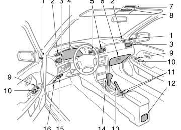
Instrument panel overview
1. Rear view mirror remote control lever
2. Side defroster outlet
3. Side vent
4. Instrument cluster
5. Center vents
6. Glovebox
7. Electric moon roof switch and
personal light
8. Garage door opener box or
miscellaneous box
9. Power door lock switch
10. Power window switches
11. Cup holders
12. Cup holder or rear ashtray
13. Parking brake lever
14. Automatic transmission selector lever or
manual transmission gear shift lever
15. Auxiliary box
16. Hood lock release lever
1. Power rear view mirror control switch
2. Headlight and turn signal switch
3. Wiper and washer switches
4. Clock
5. Emergency flasher switch
6. Car audio
7. Rear window and outside rear view
mirror defoggers switch
8. Air conditioning controls
9. Front ashtray
10. Power outlet
11. Cigarette lighter
12. Ignition switch
13. Cruise control switch
14. Tilt steering lock release lever
15. Traction control system off switch
16. Instrument panel light control knob
Instrument cluster overview
1. Engine coolant temperature gauge
4. Speedometer
7. Tachometer
2. Service reminder indicators or indicator
lights
3. Fuel gauge
5. Odometer and two trip meters
8. Trip meter reset knob
6. Theft deterrent system/Engine
immobiliser system indicator light
9. Low fuel level warning light
Indicator symbols on the instrument panel
(type A)
(type B)
Brake system warning light∗1
Seat belt reminder light∗1
Discharge warning light∗1
Malfunction indicator lamp∗1
Anti-lock brake system warning light∗1
(type A)
(type B)
Open door warning light∗1
Rear light failure warning light∗1
SRS airbag warning light∗1
Low oil pressure warning light∗1
Low windshield washer fluid level warning light∗1