- 2009 Toyota 4runner Owners Manuals
- Toyota 4runner Owners Manuals
- 2005 Toyota 4runner Owners Manuals
- Toyota 4runner Owners Manuals
- 2002 Toyota 4runner Owners Manuals
- Toyota 4runner Owners Manuals
- 2010 Toyota 4runner Owners Manuals
- Toyota 4runner Owners Manuals
- 2012 Toyota 4runner Owners Manuals
- Toyota 4runner Owners Manuals
- 2001 Toyota 4runner Owners Manuals
- Toyota 4runner Owners Manuals
- 2015 Toyota 4runner Owners Manuals
- Toyota 4runner Owners Manuals
- 2006 Toyota 4runner Owners Manuals
- Toyota 4runner Owners Manuals
- 2004 Toyota 4runner Owners Manuals
- Toyota 4runner Owners Manuals
- 2003 Toyota 4runner Owners Manuals
- Toyota 4runner Owners Manuals
- 2008 Toyota 4runner Owners Manuals
- Toyota 4runner Owners Manuals
- 2014 Toyota 4runner Owners Manuals
- Toyota 4runner Owners Manuals
- 2000 Toyota 4runner Owners Manuals
- Toyota 4runner Owners Manuals
- 2011 Toyota 4runner Owners Manuals
- Toyota 4runner Owners Manuals
- 2007 Toyota 4runner Owners Manuals
- Toyota 4runner Owners Manuals
- Download PDF Manual
-
Replace the battery by using the following procedures: 1. Pull
the case out while pushing
the
lock release button to the side.
2. Remove the discharged battery. 3. Put a new battery with the positive (+)
side up. Put in the case securely.
2005 4RUNNER from Sep. ’04 Prod. (OM35843U)
’05 4Runner_U (L/O 0409)
Audio system operating hints
NOTICE
NOTICE
z Make sure that the positive side of the controller battery is facing cor- rectly.
z Do not replace the battery with wet
hands. Water may cause rust.
z Do not touch or move any compo- nents inside of the controller, or it may interfere with proper operation. z Be careful not to bend the electrode insertion of the controller battery and that dust or oil does not ad- here to the transmitter case.
z Close the battery case securely.
After replacing the battery, check that the controller operates properly. If the control- ler still does not operate properly, contact your Toyota dealer.
To ensure correct audio system op- erations: z Be careful not to spill beverages
over the audio system.
z Do not put anything other than a cassette tape or compact disc into the slot.
z The use of a cellular phone inside or near the vehicle may cause a noise from the speakers of the au- dio system. This does not indicate a malfunction.
RADIO RECEPTION Usually, a problem with radio reception does not mean there is a problem with your radio—it is just the normal result of conditions outside the vehicle. For example, nearby buildings and terrain can interfere with FM reception. Power lines or telephone wires can interfere with AM signals. And of course, radio signals have a limited range. The farther you are from a station, the weaker its signal will be. conditions change constantly as your vehicle moves.
In addition,
reception
signals are
Here are some common reception prob- lems that probably do not indicate a prob- lem with your radio: FM Fading and drifting stations—Generally, the effective range of FM is about 40 km (25
miles). Once outside this range, you may notice fading and drifting, which increase with the distance from the radio transmit- ter. They are often accompanied by distor- tion. Multi−path—FM reflective, making it possible for two signals to reach your antenna at the same time. If this happens, the signals will cancel each oth- er out, causing a momentary flutter or loss of reception. Static and fluttering—These occur when signals are blocked by buildings, trees, or other large objects. Increasing the bass level may reduce static and fluttering. the FM signal you Station swapping—If are interrupted or weak- is ened, and there is another strong station nearby on the FM band, your radio may tune in the second station until the origi- nal signal can be picked up again.listening to
225
2005 4RUNNER from Sep. ’04 Prod. (OM35843U)
’05 4Runner_U (L/O 0409)
Use high−quality cassettes. D Low−quality cassette tapes can cause many problems, including poor sound, inconsistent and constant auto−reversing. They can also get stuck or tangled in the cassette player.
playing
speed,
D Do not use a cassette if it has been damaged or tangled or if its label is peeling off.
D Do not leave a cassette in the player if you are not listening to it, especially if it is hot outside.
D Store cassettes in their cases and out
of direct sunlight.
D Avoid using cassettes with a total play- ing time longer than 100 minutes (50
minutes per side). The tape used in these cassettes is thin and could get stuck or tangled in the cassette player.they can
AM Fading—AM broadcasts are reflected by the upper atmosphere—especially at night. These reflected signals can interfere with those received directly from the radio sta- tion, causing the radio station to sound alternately strong and weak. Station interference—When a reflected sig- nal and a signal received directly from a radio station are very nearly the same frequency, interfere with each other, making it difficult to hear the broad- cast. Static—AM is easily affected by external sources of electrical noise, such as high tension power lines, lightening, or electri- cal motors. This results in static. CARING FOR YOUR CASSETTE PLAYER AND TAPES For the best performance for your cas- sette player and tapes: Clean the tape head and other parts regu- larly. D A dirty
tape head or tape path can decrease sound quality and tangle your cassette to clean them is by using a cleaning tape. (A wet type is recommended.)
tapes. The easiest way
226
CARING FOR YOUR COMPACT DISC PLAYER AND DISCS D Your compact disc player is intended for use with 12 cm (4.7 in.) discs only. D Extremely high temperatures can keep your compact disc player from working. On hot days, use the air conditioning to cool the vehicle interior before you listen to a disc.
D Bumpy roads or other vibrations may to
cause your compact disc player skip.
D If moisture gets into your compact disc player, you may not hear any sound even though your compact disc player appears the disc from the player and wait until it dries.
to be working. Remove
CAUTION
Compact disc players use an invisible laser beam which could cause hazard- ous if directed outside the unit. Be sure to operate the player correctly.
radiation exposure
2005 4RUNNER from Sep. ’04 Prod. (OM35843U)
’05 4Runner_U (L/O 0409)
Special shaped discs
Low quality discs
D Use only compact discs marked as shown above. The following products may not be playable on your compact disc player. Copy−protected CD CD−R (CD−Recordable) CD−RW (CD−Re−writable) CD−ROM
Transparent/translucent discs
Labeled discs
227
2005 4RUNNER from Sep. ’04 Prod. (OM35843U)
’05 4Runner_U (L/O 0409)
NOTICE
Do not use special shaped, transpar- ent/translucent, low quality or labeled discs such as those shown in the il- lustrations. The use of such discs may damage the player or changer, or it may be the disc.
impossible
to eject
Correct
Wrong
inserting
D Handle compact discs carefully, espe- them. cially when you are them on the edge and do not Hold them. Avoid getting fingerprints bend on them, particularly on the shiny side. D Dirt, scratches, warping, pin holes, or other disc damage could cause the player to skip or to repeat a section of a track. (To see a pin hole, hold the disc up to the light.)
D Remove discs from the compact disc player when you are not listening to them. Store them in their plastic cases away from moisture, heat, and direct sunlight.
To clean a compact disc: Wipe it with a soft, lint−free cloth that has been damp- ened with water. Wipe in a straight line from the center to the edge of the disc (not in circles). Dry it with another soft, lint−free cloth. Do not use a conventional record cleaner or anti−static device.
2005 4RUNNER from Sep. ’04 Prod. (OM35843U)
228
’05 4Runner_U (L/O 0409)
SECTION 1− 9
OPERATION OF INSTRUMENTS AND CONTROLS Air conditioning system Controls Air flow selector settings Operating tips Instrument panel and rear vents Air conditioning filter
. . . . . . . . . . . . . . . . . . . . . . . . . . . . . . . . . . . . . . . . . . . . . . . . . . . . . . . . . . . . . . . . . . . . . . . . . . . . . . . . . . . . . . . . . . . . . . . . . . . . . . . . . . . . . . . . . . . . . . . . . . . . . . . . . . . . . . . . . . . . . . . . . . . . . . . . . . . . . . . . . . . . . . . . . . . . . . . . . . . . . . . . . . . . . . . . . . . . . . . . . . . .
230
237
237
240
241229
2005 4RUNNER from Sep. ’04 Prod. (OM35843U)
Controls (without “DUAL” button)
’05 4Runner_U (L/O 0409)
1. Fan speed selector 2. “AUTO” button 3. Temperature selector 4. “A/C” button 5. Air flow selector 6. Air intake selector 7. “OFF” button
230
2005 4RUNNER from Sep. ’04 Prod. (OM35843U)
“AUTO” button For automatic operation of the air condi- tioning, push the “AUTO” button. An indi- cator light will illuminate to show that the automatic operation mode has been se- lected. In the automatic operation mode, the air conditioning selects the most suitable fan speed, air flow, air intake and on−off of the air conditioning according to the tem- perature. When you push the “AUTO” button with the air intake mode at FRESH, internal circulation may be applied for maximum cooling. You may use manual controls if you want to select your own settings. Fan speed selector Select the mode button you desire to ad- just the fan speed and push it. An indica- tor light will illuminate to show which fan speed mode is being selected. In automatic operation, you do not have to adjust the fan speed unless you desire another fan speed mode.
’05 4Runner_U (L/O 0409)
the the
the to decrease
temperature, push it, push
Temperature selector To increase “UP” side, “DOWN” side. “LO” appears when you adjust to maxi- mum cooling, and “HI” appears when you adjust to maximum warming. “OFF” button Push the “OFF” button to turn off the air conditioning system.
illuminate
to select
the buttons
to show which air
Air flow selector Push one of the vents used for air flow. An indicator light will flow mode is being selected. In automatic operation, you do not have to select the air flow unless you desire another air flow mode. 1. Panel—Air
the panel vents and rear vents.
instrument
flows
from
2. Bi−level—Air flows from both the floor vents, the instrument panel vents and rear vents.
3. Floor—Air flows mainly from the floor
vents.
231
2005 4RUNNER from Sep. ’04 Prod. (OM35843U)
4. Floor/Windshield—Air
flows mainly floor vents and windshield
the
from vents.
5. Windshield—Air flows mainly from the
windshield vents. When this button is pressed, air flows mainly from the windshield vents and turns on the defogging function with the purpose of clearing the front view. Pressing this button once again returns the air flow mode to the last one used. This button allows to select FRESH automatically. This is to clean up the front view more quickly. If you want to return the setting to RECIRCULATE mode, press the air in- take selector button once again. Press the “A/C” button for dehumidified heating or cooling. This setting clears the front view more quickly.
the air
intake
For details about air flow selector settings, see “Air flow selector settings” described below.
232
’05 4Runner_U (L/O 0409)
“A/C” button To turn on the air conditioning, push the “A/C” button. The “A/C” button indicator will come on. To turn the air conditioning off, push the button again. If the “A/C” button indicator flashes, there is a problem in the air conditioning system and the air conditioning automatically shuts off. If this happens, take your ve- hicle to a Toyota dealer for service.
Air intake selector Push the button to select the air source. An indicator light will illuminate to show which the air source is being selected. 1. Recirculate—Recirculates the air inside
the vehicle.
2. Fresh—Draws outside air into the sys-
tem.
To prevent fogging up of the windshield, the air intake mode may change automati- cally to FRESH depending on the condi- tion of the air conditioning system.
2005 4RUNNER from Sep. ’04 Prod. (OM35843U)
’05 4Runner_U (L/O 0409)
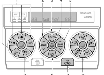
Controls (with “DUAL” button)
1. Fan speed selector 2. Temperature selector
(at the independent mode: for driver) (at the linked mode: for driver and front passenger)
3. “AUTO” button 4. “DUAL” button 5. Temperature selector (for front passenger)
6. Air flow selector 7. Air intake selector 8. “A/C” button 9. “OFF” button
233
2005 4RUNNER from Sep. ’04 Prod. (OM35843U)
’05 4Runner_U (L/O 0409)
“AUTO” button For automatic operation of the air condi- tioning, push the “AUTO” button. An indi- cator light will illuminate to show that the automatic operation mode has been se- lected. In the automatic operation mode, the air conditioning selects the most suitable fan speed, air flow, air intake and on−off of the air conditioning according to the tem- perature. When you push the “AUTO” button with the air intake mode at FRESH, internal circulation may be applied for maximum cooling. You may use manual controls if you want to select your own settings. Fan speed selector Select the mode button you desire to ad- just the fan speed and push it. An indica- tor light will illuminate to show which fan speed mode is being selected. In automatic operation, you do not have to adjust the fan speed unless you desire another fan speed mode.
234
the mode
the button changes
Temperature selector To increase the temperature, push the “Ɯ” side, to decrease it, push the “Ɲ” side. “LO” appears when you adjust to maxi- mum cooling, and “HI” appears when you adjust to maximum warming. “DUAL” button This button is used to set the tempera- tures independently for the driver’s seat and front passenger seat. Pushing from independent and linked. Independent mode: Temperatures can be set independently for the driver’s seat and front passenger’s seat. An indicator light will illuminated to show that the indepen- dent mode has been selected. Linked mode: The same temperature is set for the driver’s seat and front passen- ger’s seat. When the temperature for the front pas- senger’s seat is changed in linked mode, the mode is changed automatically to in- dependent mode. “OFF” button Push the “OFF” button to turn off the air conditioning system.
illuminate
to select
the buttons
Air flow selector Push one of the vents used for air flow. An indicator light will flow mode is being selected. In automatic operation, you do not have to select the air flow unless you desire another air flow mode.
to show which air
2005 4RUNNER from Sep. ’04 Prod. (OM35843U)
1. Panel—Air
the panel vents and rear vents.
flows
from
instrument
2. Bi−level—Air flows from both the floor vents, the instrument panel vents and rear vents.
3. Floor—Air flows mainly from the floor
vents.
4. Floor/Windshield—Air
flows mainly floor vents and windshield
the
from vents.
5. Windshield—Air flows mainly from the
windshield vents. When this button is pressed, air flows mainly from the windshield vents and turns on the defogging function with the purpose of clearing the front view. Pressing this button once again returns the air flow mode to the last one used. This button allows to select FRESH automatically. This is to clean up the front view more quickly. If you want to return the setting to RECIRCULATE mode, press the air in- take selector button once again. Press the “A/C” button for dehumidified heating or cooling. This setting clears the front view more quickly.
the air
intake
’05 4Runner_U (L/O 0409)
For details about air flow selector settings, see “Air flow selector settings” described below.
Air intake selector Push the button to select the air source. An indicator light will illuminate to show which the air source is being selected. 1. Recirculate—Recirculates the air inside
the vehicle.
2. Fresh—Draws outside air into the sys-
tem.
To prevent fogging up of the windshield, the air intake mode may change automati- cally to FRESH depending on the condi- tion of the air conditioning system.
235
2005 4RUNNER from Sep. ’04 Prod. (OM35843U)
’05 4Runner_U (L/O 0409)
“A/C” button To turn on the air conditioning, push the “A/C” button. The “A/C” button indicator will come on. To turn the air conditioning off, push the button again. If the “A/C” button indicator flashes, there is a problem in the air conditioning system and the air conditioning automatically shuts off. If this happens, take your ve- hicle to your Toyota dealer for service.
236
2005 4RUNNER from Sep. ’04 Prod. (OM35843U)
Air flow selector settings
’05 4Runner_U (L/O 0409)
Operating tips D To cool off your Toyota after
it has been parked in the hot sun, drive with the windows open for a few minutes. This vents the hot air, allowing the air conditioning to cool the interior more quickly.
D Make sure the air intake grilles in front of the windshield are not blocked (by leaves or snow, for example).
D On humid days, do not blow cold air on the windshield. The windshield could fog up because of the difference in air temperature on the inside and outside of the windshield.
D Keep the area under the front seats clear to allow air to circulate through- out the vehicle.
for a minute
D On cold days, set the fan speed to high the intake ducts of snow or moisture. This can reduce the amount of fogging on the windows.
to help clear
D When driving on dusty roads, close all windows. If dust thrown up by the ve- hicle is still drawn into the vehicle after closing the windows, it is recommended that the air intake selector be set to FRESH and the fan speed selector to any setting.
237
2005 4RUNNER from Sep. ’04 Prod. (OM35843U)
’05 4Runner_U (L/O 0409)
D If following another vehicle on a dusty road, or driving in windy and dusty conditions, it is recommended that the air intake selector be temporarily set to RECIRCULATE, which will close off the outside passage and prevent outside air and dust from entering the vehicle interior.
Heating For best results, set controls as follows: For automatic operation—
Air conditioning For best results, set controls as follows: For automatic operation—
Press in the “AUTO” button. Temperature—To the desired
temperature
Air intake—FRESH (outside air) Air conditioning—OFF
Press in the “AUTO” button. Temperature—To the desired
temperature
Air intake—FRESH (outside air) Air conditioning—ON
For manual operation—
For manual operation—
Fan speed—To the desired fan speed Temperature—Towards WARM Air intake—FRESH (outside air) Air flow—FLOOR Air conditioning—OFF
Fan speed—To the desired fan speed Temperature—Towards COLD Air intake—FRESH (outside air) Air flow—PANEL Air conditioning—ON
for a
few minutes. To keep
D For quick heating, select recirculated air the windows from fogging, select fresh af- ter the vehicle interior has been war- med.
D Press the “A/C” button on for dehumidi-
fied heating.
D Choose floor/windshield air flow to heat the vehicle interior while defrosting or defogging the windshield.
238
D For quick cooling, select recirculated
air for a few minutes.
2005 4RUNNER from Sep. ’04 Prod. (OM35843U)
’05 4Runner_U (L/O 0409)
Ventilation For best results, set controls as follows: For automatic operation—
Press in the “AUTO” button. Temperature—Towards low temperature Air intake—FRESH (outside air) Air conditioning—OFF
For manual operation—
Fan speed—To the desired fan speed Temperature—Towards COLD Air intake—FRESH (outside air) Air flow—PANEL Air conditioning—OFF
Defogging and defrosting —The inside of the windshield For best results, set controls as follows: —For automatic operation
Temperature—Towards high temperature to heat; low temperature to cool
Air intake—FRESH (outside air) Air flow—WINDSHIELD
—For manual operation
Fan speed—To the desired fan speed Temperature—Towards high temperature to heat; low temperature to cool
Air intake—FRESH (outside air) Air flow—WINDSHIELD
the windshield air
Pressing flow button turns on the defogging function with the purpose of clearing the front view. When pressing the windshield air flow but- ton, the air intake selects FRESH auto- matically. This is to clean up the front view more quickly. If you want to return the setting to RE- CIRCULATE mode, press intake selector button once again.
the air
the “A/C” button
Press for dehumidified heating or cooling. This setting clears the front view more quickly. D On humid days, do not blow cold air on the windshield—the difference be- tween the outside and inside tempera- tures could make the fogging worse.
—The outside of the windshield For best results, set controls as follows: —For automatic operation
Temperature—Towards high temperature Air intake—FRESH (outside air) Air flow—WINDSHIELD
—For manual operation
Fan speed—To the desired fan speed Temperature—Towards high temperature Air intake—FRESH (outside air) Air flow—WINDSHIELD
239
2005 4RUNNER from Sep. ’04 Prod. (OM35843U)
’05 4Runner_U (L/O 0409)
Instrument panel and rear vents
Center vents
Rear vents
If air flow control is not satisfactory, check the instrument panel vents and rear vents. The instrument panel vents and rear vents may be opened or closed as shown.
the windshield air
Pressing flow button turns on the defogging function with the purpose of clearing the front view. When pressing the windshield air flow but- ton, the air intake selects FRESH auto- matically. This is to clean up the front view more quickly. If you want to return the setting to RE- CIRCULATE mode, press intake selector button once again. Press for dehumidified heating or cooling. This setting clears the front view more quickly. D To heat the vehicle interior while de- choose
the “A/C” button
windshield,
the air
frosting floor/windshield air flow.
the
240
Side vents
2005 4RUNNER from Sep. ’04 Prod. (OM35843U)
’05 4Runner_U (L/O 0409)
Air conditioning filter—
The air conditioning filter information label is placed on the upper right side of the glove box as shown and indi- cates that a filter has been installed. The air conditioning filter prevents dust from entering the vehicle through the air conditioning vent.
The air conditioning filter is behind the glove box.
—Checking and replacing the air conditioning filter The air conditioning filter may clog af- ter long use. The filter may need to be replaced if the air flow of the air condi- tioning and heater experiences extreme reductions in operating efficiency, or if the windows begin to fog up easily. To maintain the air conditioning efficiency, inspect and replace the air conditioning filter according to the maintenance sched- ule. In dusty areas or areas with heavy traffic flow, such as inner city or desert areas, early replacement may be required. (For scheduled maintenance information, please refer the “Scheduled Mainte- nance Guide” or “Owner’s Manual Supple- ment”.)
to
241
2005 4RUNNER from Sep. ’04 Prod. (OM35843U)
’05 4Runner_U (L/O 0409)
2. Push in each side of the glove box
to disconnect the claws.
3. Remove the filter case by holding
both sides.
1. Open
the glove box. Remove
the screw with a Phillips−head screw- driver and slide the hook as shown.
242
2005 4RUNNER from Sep. ’04 Prod. (OM35843U)
’05 4Runner_U (L/O 0409)
INFORMATION
The air filter should be installed prop- erly in position. The use of air condi- tioning with filter removed may cause deteriorated dustproof per- formance and then affect air condi- tioning performance.
the air
4. Remove
case.
the
filter
from
the
filter
5. Inspect the filter on the surface. If it is the just moderately dusty, it may be cleaned by blowing compressed air from the reverse surface. Do not wash or oil the filter. If it is dirty, it should be replaced. When setting the filter to the filter case, ensure that the flat side of the filter is down and the ribbed side is up. Position the filter case so that the “↑UP” mark is pointing up and install it in the vehicle.
243
2005 4RUNNER from Sep. ’04 Prod. (OM35843U)
’05 4Runner_U (L/O 0409)
244
2005 4RUNNER from Sep. ’04 Prod. (OM35843U)
’05 4Runner_U (L/O 0409)
SECTION 1− 10
OPERATION OF INSTRUMENTS AND CONTROLS Other equipment Multi−information display Compass Rear view monitor system Power outlet Glove box Garage door opener Auxiliary boxes Rear console box Tissue box holder Coin holder Trash holder Front cup holders Rear cup holders and tray Rear cup holders Bottle holders Tie−down hooks Grocery bag hooks Cargo net hooks Luggage cover Double deck Roof luggage carrier Floor mat
. . . . . . . . . . . . . . . . . . . . . . . . . . . . . . . . . . . . . . . . . . . . . . . . . . . . . . . . . . . . . . . . . . . . . . . . . . . . . . . . . . . . . . . . . . . . . . . . . . . . . . . . . . . . . . . . . . . . . . . . . . . . . . . . . . . . . . . . . . . . . . . . . . . . . . . . . . . . . . . . . . . . . . . . . . . . . . . . . . . . . . . . . . . . . . . . . . . . . . . . . . . . . . . . . . . . . . . . . . . . . . . . . . . . . . . . . . . . . . . . . . . . . . . . . . . . . . . . . . . . . . . . . . . . . . . . . . . . . . . . . . . . . . . . . . . . . . . . . . . . . . . . . . . . . . . . . . . . . . . . . . . . . . . . . . . . . . . . . . . . . . . . . . . . . . . . . . . . . . . . . . . . . . . . . . . . . . . . . . . . . . . . . . . . . . . . . . . . . . . . . . . . . . . . . . . . . . . . . . . . . . . . . . . . . . . . . . . . . . . . . . . . . . . . . . . . . . . . . . . . . . . . . . . . . . . . . . . . . . . . . . . . . . . . . . . . . . . . . . . . . . . . . . . . . . . . . . . . . . . . . . . . . . . . . . . . . . . . . . . . . . . . . . . . . . . . . . . . . . . . . . . . . . . . . . . . . . . . . . . . . . . . . . . . . . . . . . . . . . . . . . . . . . . . . . . . . . . . . . . . . . . . . . . . . . . . . . . . . . . . . . . . . . . . . . . . . . . . . . . . . . . . . . . . . . . . . . . . . . . . . . . . . . . . . . . . . . . . . . . . . . . . . . . . . . . . . . . . . . . . . . . . . . . . . . . . . . . . . . . . . . . . . . . . . . . . . . . . . . . . . . . . . . . . . . . . . . . . . . . . . . . . . . . . . . . . . . . . . . . . . . . . . . . . . . . . . . . . . . . . . . . . . . . . . . . . . . . . . . . . . . . . . . . . . . . . . . . . . . . . . . . . . . . . . . . . . . . . . . . . . . . . . . . . . . . . . . . . . . . . . . . . . . . . . . . . . . . . . . . . . . . . . . . . . . . . . . . . . . . . . . . . . . . . . . . . . . . . . . . . . .
246
249
254
258
260
261
264
266
267
267
268
269
270
271
272
273
273
273
274
275
276
277245
2005 4RUNNER from Sep. ’04 Prod. (OM35843U)
’05 4Runner_U (L/O 0409)
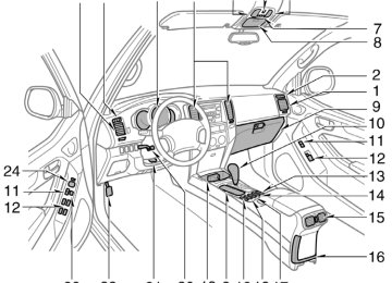
Multi−information display—
1. “RESET” button 2. “MODE” button 3. Air conditioning system without “DUAL”
button—Cruise information display Air conditioning system with “DUAL” button—Outside temperature and cruise information display
4. Clock 5. Air conditioning system without “DUAL”
button only—Outside temperature display
6. “:00” button 7. “M” button 8. “H” button
246
2005 4RUNNER from Sep. ’04 Prod. (OM35843U)
’05 4Runner_U (L/O 0409)
—Clock
—Outside temperature display (air conditioning system without “DUAL” button)
the
ignition switch
the multi−information display
—Before using the multi−information display Operate with the ignition switch on. to When “ON”, the last previously used mode dis- played just before the ignition switch is turned off will appear. If the electrical power source has been disconnected the multi−information display, the display will automatically be set to the initial mode.
turned
from
is
CAUTION
Do not adjust the display while the vehicle is moving. Be sure to adjust the display only when the vehicle is stopped.
the
time
To reset the hour: Push the “H” button. To reset the minutes: Push the “M” button. If quick adjustment to a full hour is de- sired, push the “:00” button. if the “:00” button is de- For example, pressed when is between 1:01—1:29, the time will change to 1:00. If the time will change to 2:00. The key must be in the “ACC” or “ON” position. If the electrical power source has been disconnected from the clock, the time dis- play will automatically be set to 1:00 (one o’clock).
is between 1:30—1:59,
time
the
from
temperature
the outside air
The displayed ranges −30_C (−22_F) up to 50_C (122_F). The key must be in the “ON” position. If an abnormality exists in the connection of temperature sensor, “−−_C” (“−−_F”) will appear on the display. If “−−_C” (“−−_F”) appears on the display, contact your Toyota dealer. There may be a case that “−−_C” (“−−_F”) appears momentarily when the ignition is quickly turned to “ON”. It is normal if it goes out soon.
247
2005 4RUNNER from Sep. ’04 Prod. (OM35843U)
’05 4Runner_U (L/O 0409)
—Cruise information display
Air conditioning system with “DUAL” button only—
temperature display
The outside (air conditioning system with “DUAL” but- ton) and cruise information display indi- cates the following information. Every time you push the “MODE” but- ton, the display toggles through this information. 1. Outside temperature 2. Driving range 3. Average fuel consumption 4. Average vehicle speed 5. Display off The displayed values in the cruise infor- mation display indicate general driving conditions. Accuracy varies with driving habits and road conditions.
1. Outside temperature (“OUTSIDE _C”
or “OUTSIDE _F”)
from
temperature
the outside air
The displayed value is updated every 1
second. The displayed ranges −30_C (−22_F) up to 50_C (122_F). If an abnormality exists in the connection of temperature sensor, “−−_C” (“−−_F”) will appear on the display. If “−−_C” (“−−_F”) appears on the display, contact your Toyota dealer. There may be a case that “−−_C” (“−−_F”) appears momentarily when the ignition is quickly turned to “ON”. It is normal if it goes out soon.248
2005 4RUNNER from Sep. ’04 Prod. (OM35843U)
’05 4Runner_U (L/O 0409)
2. Driving range
(“RANGE MI” or “RANGE km”)
3. Average fuel consumption
(“AVG. MPG” or “AVG. L/100 km”)
Compass
It
the
fuel
indicates
fuel gauge reaches “E”.
The distance the vehicle can travel with the remaining is calculated and displayed based on the quantity of re- maining fuel and past fuel consumption. The driving range display the approximate distance that you can drive until is different from the actual distance traveled. The displayed value is updated about ev- ery 10 seconds. Every time you refuel the vehicle, the cal- culation is reset. The actual driving range varies with driv- ing habits and road conditions. If fuel con- sumption is good, the driving range will be longer than indicated. If fuel consumption is poor, the driving range will be shorter than indicated. If the low fuel level warning light comes on, refuel the vehicle even if the display indicates that the vehicle can be driven further.
total
Average fuel consumption is calculated and displayed based on total driving distance and fuel consumption with the engine running. The displayed value is updated about ev- ery 10 seconds. To the “RESET” button about 1 second. 4. Average vehicle speed
calculation,
reset
push
the
(“AVG. MPH” or “AVG. km/h”)
Average vehicle speed is calculated and displayed based on total driving dis- tance and total driving time with the engine running. The displayed value is updated about ev- ery 10 seconds. To the “RESET” button about 1 second.
calculation,
reset
push
the
The direction is indicated on the inside rear view mirror. If the ignition switch was turned off with the system on, the system will automati- cally turn back on when the ignition switch is turned on. Push the “COMP” switch to turn the com- pass system on and off.
249
2005 4RUNNER from Sep. ’04 Prod. (OM35843U)
indicates
the vehicle
the direction The compass that the above case, it shows that the vehicle is heading north.
is heading.
In
Displays
NE SE SW NW
Directions
North
Northeast
East
Southeast
South
Southwest
West
Northwest
The compass may not show the correct direction in the following conditions: D The vehicle is stopped immediately af-
ter turning.
D The compass does not adjust while the
vehicle is stopped.
D The ignition switch is turned off imme-
diately after turning.
D The vehicle is on an inclined surface.
250
’05 4Runner_U (L/O 0409)
D The vehicle is in a place where the earth’s magnetic field is subject to in- terference by artificial magnetic fields (underground parking, under a steel tower, between buildings, roof parking, near a crossing, near a large vehicle, etc.).
D The vehicle is magnetized. (There is a magnet or a metal object on or near the inside rear view mirror.)
the deviation
D The battery has been disconnected. If your vehicle is out of the set zone, refer to “CALIBRATING THE COMPASS” below to set the zone number. If the compass works to calibrate the direction automati- cally while the vehicle is in motion. For additional precision or calibrating, see COMPASS” below.
for complete THE
“CALIBRATING
is small,
Compass sensor
The compass sensor is on the wind- shield.
NOTICE
Do not put magnets or a metal object on or near the inside rear view mirror of the vehicle. Doing this may cause malfunction of the compass sensor.
2005 4RUNNER from Sep. ’04 Prod. (OM35843U)
’05 4Runner_U (L/O 0409)
251
2005 4RUNNER from Sep. ’04 Prod. (OM35843U)
the
from
CALIBRATING THE COMPASS (deviation calibration) the compass The direction display on true direction deter- deviates mined by the earth’s magnetic field. The angle of deviation varies according to the geographic position of the vehicle. To adjust this deviation, stop the vehicle, then push and hold the “COMP” switch until the zone number appears on the dis- play. Then push the “COMP” switch, refer- ring to the following map to select the number of the zone where the vehicle is.
’05 4Runner_U (L/O 0409)
Samoa: 5
Guam:
Saipan: 8
After calibration, leaving the system for several seconds returns it to the compass mode.
CAUTION
Do not adjust the display while the vehicle is moving. Be sure to adjust the display only when the vehicle is stopped.
Zone number
252
2005 4RUNNER from Sep. ’04 Prod. (OM35843U)
’05 4Runner_U (L/O 0409)
the direction display on
CALIBRATING THE COMPASS (circling calibration) Sometimes the compass may not change after a turn. To rectify this, stop the vehicle and push and hold the “COMP” switch until “C” appears on the display. If “C” appears on the display because of a drastic change in the magnetic field, perform circling calibration.
in a circle, drive around
Drive the vehicle in a circle at 8 km/h (5
mph) or less. If there is not enough space to drive the block. After driving 1 to 3 circles in the above method, calibration is completed when the direction is shown on the display. If calibration cannot be performed because of the magnetized vehicle etc., take your vehicle to Toyota dealer.Perform circling calibration just after you have purchased your Toyota. And then always perform circling calibration after the battery has been removed, re- placed or disconnected. D Do not perform circling calibration of the compass the earth’s magnetic field is subject to in- terference by artificial magnetic fields (underground parking, under a steel tower, between buildings, roof parking, near a crossing, near a large vehicle, etc.).
in a place where
D During calibration, do not operate elec- tric systems (moon roof, power win- dows, etc.) as they may interfere with the calibration.
253
2005 4RUNNER from Sep. ’04 Prod. (OM35843U)
’05 4Runner_U (L/O 0409)
CAUTION
D When doing the circling calibration, be sure to secure a wide space, and watch out for people and ve- hicles in the neighborhood. Do not violate any local traffic rules while performing circling calibration.
D Do not adjust the display while the vehicle is moving. Be sure to adjust the display only when the vehicle is stopped.
Rear view monitor system The rear view monitor system assists the driver by displaying images of the rear of the vehicle during backing up. The displayed image on the screen is a horizontally reversed mirror image of the inside rear view mirror. To display the rear view on the screen, place the selector lever in the “R” posi- tion when the in the “ON” position. If you move the selector lever out of the “R” position, the previous screen. Operating another func- tion of the navigation system will display another screen. The rear view monitor system is an auxil- iary device intended to back up. When backing up, be sure to check behind and all around the vehicle visually.
the screen returns
ignition switch
to
CAUTION
D Do not rely entirely on the rear
view monitor system. Use caution just as you would when backing up any vehicle.
254
image on
D Never back up while looking only at the screen. The the screen may differ from actual con- ditions. If you back up while look- ing only at the screen, you may hit a vehicle or have an unexpected accident. When backing up, be sure to check behind and all around the vehicle visually and with mirrors before proceeding.
NOTICE
z Do not use the system when the back door is not completely closed. z If the back of the vehicle is hit, the position and mounting angle of the camera may slip. Be sure to have the camera’s position and mounting angle checked at your Toyota deal- er.
z If the temperature changes rapidly, such as when hot water is poured on it in cold weather, the system may not operate normally.
2005 4RUNNER from Sep. ’04 Prod. (OM35843U)
z If the camera lens becomes dirty, it cannot transmit a clear If water droplets, snow, or mud ad- here to the lens, rinse with water and wipe with a soft cloth. If the lens is extremely dirty, wash with a mild cleanser and rinse.
image.
z Use your own eyes to assure safety as the displayed image may become darker and moving images may be slightly distorted when the display is cold.
’05 4Runner_U (L/O 0409)
AREA DISPLAYED ON SCREEN Image is displayed approximately level on screen. D The area detected by the camera is limited. The camera does not detect objects which are close to either corner of the bumper or under the bumper.
On screen
Corners of bumper
255
2005 4RUNNER from Sep. ’04 Prod. (OM35843U)
’05 4Runner_U (L/O 0409)
that appears on
The distance the screen between three−dimensional ob- jects (such as vehicles) and flat sur- faces (such as the road) and the actual distance differ as follows. In reality, A=B
D The area displayed on the screen may vary according to vehicle status or road conditions.
On screen
256
2005 4RUNNER from Sep. ’04 Prod. (OM35843U)
’05 4Runner_U (L/O 0409)
When water droplets are adhering to the camera, or when humidity is high (for example, when it rains) When mud) is adhering to the camera When the sun or the beam of head- lights is shining directly into the cam- era lens
foreign matter
(for example,
D If a bright light (for example, sunlight reflected off the vehicle body) is picked up by the camera, the smear effect∗ peculiar to the CCD camera may occur. ∗: Smear effect—A phenomenon that oc- curs when a bright light (for example, sun- is light reflected off picked up by trans- mitted by light source appears to have a vertical streak above and below it.
the camera; when
the vehicle body)
the camera,
the
257
2005 4RUNNER from Sep. ’04 Prod. (OM35843U)
THE REAR VIEW MONITOR SYSTEM CAMERA D The rear view monitor system camera is located on the back door as shown in the illustration.
D The rear view monitor system camera uses a special lens. The distance of the images that appear on the screen differs from the actual distance.
the
to see
images on
D In the following cases, it may become the
difficult screen, but this is not a malfunction. In the dark (for example, at night) When the temperature near the lens is high or low
’05 4Runner_U (L/O 0409)
Power outlet (12 VDC)
NOTICE
the
fuse
z To prevent
from being blown, do not use the electricity over the total vehicle capacity of 12
VDC/120W.z To prevent the battery from being discharged, do not use the power outlets longer than necessary when the engine is not running.
z Close the power outlet
lids when the power outlets are not in use. Inserting anything other than an ap- propriate plug that fits the outlet, or allowing any liquid to get into the outlet may cause electrical fail- ure or short circuits.
Luggage compartment
for
The power outlets are designed power supply for car accessories. In the rear console box—To use the power outlet, push the lid of the auxil- iary box to open. The key must be in the “ACC” or “ON” position for the power outlet to be used.
Rear console box
258
2005 4RUNNER from Sep. ’04 Prod. (OM35843U)
’05 4Runner_U (L/O 0409)
Power outlet (115 VAC)
This power outlet is designed for use as a power supply for electric ap- pliances in the vehicle. The key must be in the “ON” position for the power outlet to be used. The maximum capacity for this power out- let is 115 VAC/100W. If you attempt to use an appliance that requires more than 115 VAC or 100W, the protection circuit will activate and cut the power supply. The power supply will restart automatically when you use an appliance that operates within the 115 VAC/100W limits.
To use the power outlet, push the main switch on the instrument panel. An indicator light will illuminate to indicate that the power outlet is ready for use. Push the main switch once again to turn the power outlet off. When the power out- let is not in use, make sure that the main switch is turned off.
NOTICE
z To prevent the battery from being discharged, do not use the power outlet longer than necessary when the engine is not running.
z Close the power outlet lid when the power outlet is not in use. Inserting anything other than an appropriate plug that fits the outlet may cause electrical failure or short circuits.
The power outlet is not designed for the following electric appliances even though their power consumption is un- der 115 VAC/100W. These appliances may not operate properly.
259
2005 4RUNNER from Sep. ’04 Prod. (OM35843U)
’05 4Runner_U (L/O 0409)
Glove box
D Appliances with high initial peak watt- age: cathode−ray tube type televisions, compressor−driven refrigerators, electric pumps, electric tools, etc.
D Measuring devices which process pre- cise data: medical equipment, measur- ing instruments, etc.
D Other appliances requiring an extremely stable power supply: microcomputer− controlled electric blankets, touch sen- sor lamps, etc.
Certain electrical appliances may cause radio noise.
To use the glove box, do this. To open: Pull the lever. With the instrument panel lights on, the glove box light will come on. To lock: Insert the master key and turn it clockwise.
CAUTION
To reduce the chance of in case of an accident or a sudden stop, always keep the glove box door closed while driving.
injury
260
2005 4RUNNER from Sep. ’04 Prod. (OM35843U)
’05 4Runner_U (L/O 0409)
Garage door opener
On some models, an auxiliary box is located inside the glove box. To increase the capacity of the glove box, raise the lower panel of the auxiliary box.
The garage door opener ( Universal Transceiver) is manufactured under license from HomeLinkR and can be programmed to operate garage doors, gates, entry doors, door locks, home lighting systems, and security systems, etc.
transmitter prior
(a) Programming the HomeLinkR The HomeLinkR in your vehicle has 3
buttons and you can store one program for each button. To ensure correct programming into the HomeLinkR, install a new battery in the hand−held to program- ming. The battery side of the hand−held trans- mitter must be pointed away the HomeLinkR during the programming pro- cess. For Canadian users, follow the procedure “Programming an entrance gate/pro- in gramming all devices the Canadian market”. 1. Decide which of 3 HomeLinkR buttonsfrom
in
you want to program.
2. Place your hand−held garage transmit- ter 25 to 75 mm (1 to 3 in.) away from the surface of the HomeLinkR.
Keep the indicator light on the HomeLinkR in view while programming.
261
2005 4RUNNER from Sep. ’04 Prod. (OM35843U)
’05 4Runner_U (L/O 0409)
3. Simultaneously press and hold
the hand−held garage transmitter button along with the selected HomeLinkR but- ton.
4. When
the
indicator
the HomeLinkR changes from a slow to a rapid flash after 20 seconds, you can release both buttons.
light on
5. Test the operation of the HomeLinkR by pressing the newly programmed button. If programming a garage door opener, check to see if the garage door opens and closes.
(on
light
indicator
If the garage door does not operate, iden- tify if your garage transmitter is of the “Rolling Code” type. Press and hold the programmed HomeLinkR button. The ga- rage door has the rolling code feature if the HomeLinkR) the flashes rapidly and then remains lit after 2 seconds. If your garage transmitter is the “Rolling Code” type, proceed to the heading “Programming a rolling code sys- tem”. 6. Repeat steps 2 through 5 for each re- maining HomeLinkR button to program another device.
it
is
to
is necessary
Programming a rolling code system “Rolling Code” If your device follow equipped, steps 1 through 4 under the heading “Programming the HomeLinkR” before proceeding with the steps listed below. 1. Locate the “training” button on the ceil- ing mounted garage door opener motor. The exact the button may vary by brand of garage door opener. Refer the owner’s guide supplied by the garage door opener manufacturer for the location of this “training” button.
location and color of
to
2. Press the “training” button on the ceil- ing mounted garage door opener motor. Following this step, you have 30 seconds in which to initiate step 3 below. 3. Press and release the vehicle’s pro- grammed HomeLinkR button twice. The garage door may open. the door does open, the programming process is complete. If the door does not open, press and release the button a third time. This third press and release will complete the programming process by opening the garage door.
If
now
should
recognize
The ceiling mounted garage door opener motor the HomeLinkR unit and be able activate the garage door up/down. 4. Repeat steps 1 through 3 for each re- maining HomeLinkR button to program another rolling code system.
Programming an entrance gate/program- ming all devices in the Canadian market 1. Decide which of the 3 HomeLinkR but-
2. Place
your
tons you want to program. hand−held
gate/device transmitter 25 to 75 mm (1 to 3 in.) away the HomeLinkR.
surface
from
the
of
Keep the indicator light on the HomeLinkR in view while programming. 3. Press
selected
hold
and
the
HomeLinkR button.
4. Continuously press and release (cycle) transmitter the hand−held gate/device button every two seconds until step 5
is complete. thethe HomeLinkR changes from a slow to a rapid flash after 20 seconds, you can release both buttons.
light on
5. When
indicator
262
2005 4RUNNER from Sep. ’04 Prod. (OM35843U)
’05 4Runner_U (L/O 0409)
(c) Erasing
the
entire HomeLinkR
memory (all three programs)
To erase all previously programmed codes at one time, press and hold down the 2
outside buttons for 20 seconds until the indicator light flashes. If you sell your vehicle, be sure to erase the programs stored the HomeLinkR memory.in
6. Test the operation of the HomeLinkR by pressing the newly programmed button. Check to see if the gate/device oper- ates correctly.
7. Repeat steps 1 through 6 for each re- maining HomeLinkR button to program another device.
Programming other devices To program other devices such as home security systems, home door locks or lighting, contact your authorized Toyota dealer for assistance. Reprogramming a button buttons cannot be Individual HomeLinkR erased, however, to reprogram a single button, follow the procedure “Programming the HomeLinkR”. (b) Operating the HomeLinkR To operate the appropriate HomeLinkR button to activate the programmed device. The HomeLinkR indicator light should come on. The HomeLinkR continues to send the signal for up the button is pressed.
the HomeLinkR, press
to 20 seconds as
long as
CAUTION
D When programming the HomeLinkR Universal Transceiver, you may be operating a garage door or other device. Make sure people and ob- jects are out of the way of the ga- rage door or other device to pre- vent potential harm or damage.
D Do not use this HomeLinkR Univer- sal Transceiver with any garage door opener that lacks the safety stop and reverse feature as re- quired by federal safety standards. (This includes any garage door opener model manufactured before April 1, 1982.) A garage door open- er which cannot detect an object (signaling the door to stop and re- verse), does not meet current feder- al safety standards. Using a garage door opener without these features increases risk of serious injury or death.
263
2005 4RUNNER from Sep. ’04 Prod. (OM35843U)
received,
This device complies with Part 15 of the FCC Rules and with RSS−210 of the IC Rules. Operation is subject to the fol- lowing two conditions: (1) This device may not cause harmful interference, and (2) this device must accept any interfer- ence interference that may cause undesired operation. WARNING: This transmitter has been tested and complies with FCC and IC rules. Changes or modifications not expressly approved by the party re- sponsible for compliance could void the user’s authority to operate the device.
including
264
’05 4Runner_U (L/O 0409)
Auxiliary boxes— To use the auxiliary boxes, open the lids as shown in the following illustra- tions.
CAUTION
D To reduce the chance of injury in case of an accident or a sudden stop, always keep the auxiliary box closed while driving.
D Type A—As this holder is designed for holding a light object such as eyeglasses, do not place any heavy objects in them. Heavy objects may cause the holder to open and the contents to fly out resulting in inju- ries.
NOTICE
Type A—During hot weather, the inte- rior of the vehicle becomes very hot. Do not leave anything flammable or deformable such as a lighter, glasses, etc. inside.
Type A (over head console)
Type B (instrument panel)
2005 4RUNNER from Sep. ’04 Prod. (OM35843U)
’05 4Runner_U (L/O 0409)
—Using the holding belts
Type C (rear console box)
Type E (right side of luggage compart- ment)
Type D (rear tire house)
The right side of luggage compartment auxiliary box is equipped with a belt to hold the objects. To use the belt, do the following. 1. To loosen: Pull the buckle forward. 2. To tighten: Pull on the belt. Make sure the objects are securely held.
265
2005 4RUNNER from Sep. ’04 Prod. (OM35843U)
’05 4Runner_U (L/O 0409)
CONSOLE BOX TABLE To use the console box table, open it.
CAUTION
To reduce the chance of in