- 2006 Subaru Legacy Owners Manuals
- Subaru Legacy Owners Manuals
- 2004 Subaru Legacy Owners Manuals
- Subaru Legacy Owners Manuals
- 2008 Subaru Legacy Owners Manuals
- Subaru Legacy Owners Manuals
- 2005 Subaru Legacy Owners Manuals
- Subaru Legacy Owners Manuals
- 2007 Subaru Legacy Owners Manuals
- Subaru Legacy Owners Manuals
- 2000 Subaru Legacy Owners Manuals
- Subaru Legacy Owners Manuals
- 2003 Subaru Legacy Owners Manuals
- Subaru Legacy Owners Manuals
- 2012 Subaru Legacy Owners Manuals
- Subaru Legacy Owners Manuals
- 2001 Subaru Legacy Owners Manuals
- Subaru Legacy Owners Manuals
- 2010 Subaru Legacy Owners Manuals
- Subaru Legacy Owners Manuals
- 2011 Subaru Legacy Owners Manuals
- Subaru Legacy Owners Manuals
- 2009 Subaru Legacy Owners Manuals
- Subaru Legacy Owners Manuals
- 2002 Subaru Legacy Owners Manuals
- Subaru Legacy Owners Manuals
- Download PDF Manual
-
Vehicle Dynamics Control system also becomes inoperative, causing the warning light to illuminate. Though both the Vehicle Dynamics Control and ABS systems are inop- erative in this case, the ordinary functions of the brake system are still available. You will be safe while driving with this condition, but drive carefully and have your vehicle checked at a SUBARU dealer as soon as possible.
NOTE . If the electrical circuit of the Vehicle Dynamics Control system itself mal- functions, the warning light only illumi- nates. At this time, the ABS (Anti-lock Brake System) remains fully opera- tional. . The warning light illuminates when the electronic control system of the ABS/Vehicle Dynamics Control system malfunctions. The Vehicle Dynamics Control system is probably inoperative under any of the following conditions. Have your vehicle
checked at a SUBARU dealer immedi- ately. . The warning light does not illuminate when the ignition switch is turned to the “ON” position. . The warning light illuminates while the vehicle is running. NOTE If the warning light behavior is as described in the following examples, the Vehicle Dynamics Control system may be considered normal. . The warning light illuminates right after the engine is started but turns off immediately, remaining off. . The warning light illuminates after the engine has started and turns off while the vehicle is subsequently being driven. . The warning light illuminates during driving, but it turns off immediately and remains off. ! Vehicle Dynamics Control opera-
tion indicator light
The indicator light flashes during activa- tion of the skid suppression function and during activation of the traction control function.
Instruments and controls 3-21
NOTE . The light may remain illuminated for a short period of time after the engine has been started, especially in cold weather. This does not indicate the existence of a problem. The light should turn off as soon as the engine has warmed up. . The indicator light illuminates when the engine has developed a problem and the CHECK ENGINE warning light/ malfunction indicator lamp is on. The Vehicle Dynamics Control system is probably malfunctioning under the follow- ing condition. Have your vehicle checked at a SUBARU dealer as soon as possible. . The light does not turn off even after the lapse of several minutes (the engine has warmed up) after the engine has started. & Vehicle Dynamics
Control OFF indicator light The light illuminates when the ignition switch is turned to the “ON” position and turns off after approximately 2 seconds. The light illuminates when the Vehicle Dynamics Control OFF switch is pressed to deactivate the Vehicle Dynamics Con- trol system.
– CONTINUED –
3-22 Instruments and controls
The Vehicle Dynamics Control system is probably malfunctioning under any of the following conditions. Have your vehicle checked at a SUBARU dealer immedi- ately. . The light does not illuminate when the ignition switch is turned to the “ON” position. . The light does not turn off even after a period of approximately 2 seconds after the ignition switch has been turned to the “ON” position. & Security indicator light This indicator light shows the status of the alarm system. It also indicates operation of the immobilizer system. ! Alarm system It blinks to show the driver the operational status of the alarm system. For detailed information, refer to “Alarm system” F2- 16. ! Immobilizer system This light blinks approximately 60 seconds after the ignition switch is turned from “ON” position to the “Acc” or “LOCK” position or immediately after the key is pulled out. Refer to “Immobilizer” F2-3. If the indicator light does not flash, it may indicate that immobilizer system may be
faulty. Contact your nearest SUBARU dealer immediately.
In the event that an unauthorized key (for example, an unauthorized duplicate) is used, illumi- nates.
the security indicator light
& Select lever/gear position in-
dicator
“Automatic transmission/Continuously variable transmission” F7-18. ! MT models The shift-up indicator light illuminates and informs the driver about the upshift timing for fuel-efficient driving. The gear position indicator light and the shift-up indicator can be activated or deactivated by performing the following procedure. 1. Turn the ignition switch to the “LOCK” position. 2. Press the trip knob to show “ “ The display can be switched as shown in the following illustration by pressing the trip knob.
” on the trip meter display.
” or
This indicator shows the position of the shift lever (MT models) or select lever (AT and CVT models). ! AT and CVT models When the manual mode is selected, the gear position indicator (which shows the current gear selection) and the upshift/ downshift to
light up. Refer
indicator
*1: “
” or “
” and “
” cannot be displayed when the ignition switch is in the “ON” position.
” or “
*2: MT models only
3. To change the current setting, press the trip knob for at least 2 seconds.
& High beam indicator
light
& Cruise control set in-
dicator light
Instruments and controls 3-23
: Activated : Deactivated
NOTE . The initial setting for your vehicle of the gear position indicator and shift-up indicator has been set for activation “ ” at the time of shipment from the factory. . It is not possible to change the setting of the gear position indicator/ shift-up indicator when the ignition switch is in the “ON” position. Change the setting when the ignition switch is in the “LOCK” or “Acc” position. & Turn signal indicator
lights
These lights show the operation of the turn signal or lane change signal. If the indicator lights do not blink or blink rapidly, the turn signal bulb may be burned out. Replace the bulb as soon as possible. Refer to “Replacing bulbs” F11-50.
This light shows that the headlights are in the high beam mode. This indicator light also illuminates when the headlight flasher is operated. & Cruise control indica-
tor light
indicator light
The cruise control illumi- nates when the ignition switch is turned to the “ON” position and turns off after approximately 3 seconds. This light illuminates when the “CRUISE” main switch is pressed. NOTE . If you move the cruise control lever or press the main switch button while turning the ignition switch “ON”, the cruise control function is deactivated and the “CRUISE” indicator light flashes. To reactivate the cruise control function, turn the ignition switch back to the “Acc” or “LOCK” position, and then turn it again to the “ON” position. . If this indicator light and the CHECK ENGINE warning light/malfunction in- dicator lamp flash simultaneously dur- ing driving, have the vehicle checked by your nearest SUBARU dealer.
indicator
The cruise control set light illuminates when the ignition switch is turned to the “ON” position and turns off after approximately 3 seconds. This light illuminates when vehicle speed has been set. & Headlight indicator
light
” or “
” position
This indicator light illuminates under the following conditions. . when the light switch is turned to the “ . when the light switch is in the “AUTO” position and the headlights illuminate automatically & Front fog light indicator
light (if equipped)
This indicator light front fog lights are illuminated.
illuminates while the
indicated time will change in one-minute decrements. If you keep the button pressed, the rate at which the indicated time changes will speed up.
Multi function display
With the ignition switch in the “ON” position, each successive press of the multi function display switching knob toggles the display in the following se- quence.
3-24 Instruments and controls
Clock
NOTE Your SUBARU dealer can change the settings of activating/deactivating the automatic adjustment of the clock by the GPS (Global Positioning System) (for models with the genuine SUBARU navigation system). Contact your SUBARU dealer for details.
The clock shows the time while the ignition switch is in the “Acc” or “ON” position. To adjust the time shown by the clock, press the “+” button or the “−” button. If you press the “+” button, the indicated time will change in one-minute incre- ments. the
If you press the “−” button,
& Outside temperature indica-
tor
! Road surface freeze warning indi-
cation
1) U.S.-spec. models 2) Except U.S.-spec. models
1) U.S.-spec. models 2) Except U.S.-spec. models
The outside temperature indicator shows the outside temperature in a range from −22 to 1228F (−30 to 508C). The indicator can give a false reading under any of the following conditions: . When there is too much sun. . During idling; while running at low speeds in a traffic jam; when the engine is restarted immediately following a shut- down. . When the actual outside temperature falls outside the specified indicator range.
lower,
When the outside temperature drops to 378F (38C) or the temperature indication flashes to show that the road surface may be frozen. If the outside temperature drops to 378F (38C) or lower while the display is giving an indication other than the outside temperature, the display switches to the outside temperature indication and flashes for 5 seconds before returning to its original indication. If the display is already indicating an outside temperature of 378F (38C) or lower when the ignition switch is turned to the
Instruments and controls 3-25
the indication does not
“ON” position, flash. NOTE The outside temperature indication may differ from the actual outside temperature. The road surface freeze warning indication should be treated only as a guide. Be sure to check the condition of the road surface before driving.
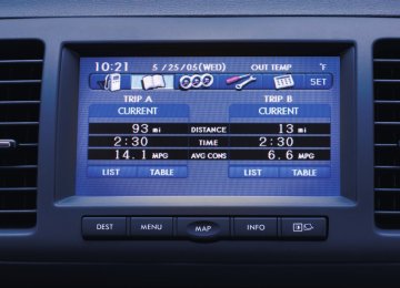
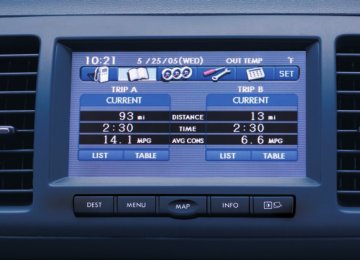
& Average fuel consumption
1) U.S.-spec. models 2) Except U.S.-spec. models
This indication shows the average rate of fuel consumption since the trip meter was last reset.
– CONTINUED –
3-26 Instruments and controls
Pressing the trip knob toggles the indica- tion between the average fuel consump- tion corresponding to the A trip meter indication and the average fuel consump- tion corresponding to the B trip meter indication. When either of the trip meter indications is reset, the corresponding average fuel consumption value is also reset. NOTE . The indicated values vary in accor- dance with changes in the vehicle’s running conditions. Also, the indicated values may differ slightly from the actual values and should thus be treated only as a guide. . When either trip meter indication is reset, the average fuel consumption corresponding to that trip meter indica- tion is not shown until the vehicle has subsequently covered a distance of 1
mile (or 1 km).& Current fuel consumption
& Driving range on remaining
fuel
1) U.S.-spec. models 2) Except U.S.-spec. models
This indication shows the rate of consumption at the present moment.
fuel
1) U.S.-spec. models 2) Except U.S.-spec. models
The driving range indicates the distance that can be driven taking into account the amount of fuel remaining in the tank and the average rate of fuel consumption. When the low fuel warning light illumi- nates, the driving range indication flashes for 5 seconds. (The display first switches to the driving range indication if it was originally giving some other indication.)
Light control switch
the position of
The light control switch only operates when the key is inserted into the ignition switch. Regardless of the light control switch, the illuminated lights are turned off when the key is removed from the ignition switch. NOTE . Even if the key is removed from the ignition switch, the lights can be illu- minated by operating the light control switch position from “OFF” to “ ” and/or “ . If the driver’s door is opened while the lights are illuminated and the key is removed from the ignition switch, the chirp sound informs the driver that the lights are illuminated.
”.
CAUTION
. Use of any lights for a long period of time while the engine is not running can cause the battery to discharge.
. Before leaving the vehicle, make sure that the light control switch is turned to the “OFF” position. If the vehicle is left unattended for
1) U.S.-spec. models 2) Except U.S.-spec. models the driving range is shown as “
”, If there is only a tiny amount of fuel left in the tank. You must refuel the vehicle immedi- ately. NOTE The driving range on remaining fuel is only a guide. The indicated value may differ from the actual driving range on remaining fuel, so you must immedi- ately fill the tank when the low fuel warning light illuminates.
Instruments and controls 3-27
a long time with the light control switch set to a position other than “OFF”, the battery may be discharged.
& Headlights
To turn on the headlights, turn the knob on the end of the turn signal lever.
first position Instrument panel lights, front side marker lights and license plate lights are on.
illumination,
tail
second position
Headlights, instrument panel illumination, front side marker lights, lights and license plate lights are on.
tail
– CONTINUED –
3-28 Instruments and controls
: Auto on/off headlights
When the ignition switch is in the “ON” position, the headlights, instrument panel illumination, front side marker lights, tail lights and license plate lights are auto- matically on or off depending on the level of the ambient light. NOTE The sensitivity of the auto on/off head- lights can be changed by your SUBARU dealer. Contact your SUBARU dealer for details. ! Sensor of the auto on/off headlights
CAUTION
& Headlight flasher
If any object is placed on or near the sensor, the sensor may not detect the level of the ambient light cor- rectly and the auto on/off headlights may not operate properly.
& High/low beam change
(dimmer)
The sensor is on the instrument panel as shown in the illustration.
To change from low beam to high beam, push the turn signal lever forward. When the headlights are on high beam, the high beam indicator light “ ” on the combina- tion meter is also on. To switch back to low beam, pull the lever back to the detent position.
CAUTION
Do not hold the lever in the flashing position for more than just a few seconds.
To flash the headlights, pull the lever toward you and then release it. The high beam will stay on for as long as you hold the lever. The headlight flasher works even though the lighting switch is in the “OFF” position.
When the headlights are on high beam, the high beam indicator light “ ” on the combination meter also illuminates.
& Daytime running light system
WARNING
The brightness of the illumination of the high beam headlights is reduced by the daytime running light system. The light switch must always be turned to the “ ” position when it is dark outside.
”
The high beam headlights will automati- cally illuminate at reduced brightness when the engine has started, under the following conditions. . The parking brake is fully released. . The light switch is in the “OFF” or “ position. . The light switch is in the “AUTO” position and the headlights do not turn on automatically. . The select lever is in a position other than the “P” position (AT and CVT mod- els). NOTE . When the light switch is in the “ ” position, the front side marker lights, tail lights and license plate lights are illuminated. . After turning on the ignition switch to the “ON” position, even if the
Instruments and controls 3-29
parking brake is applied, the daytime running lights continue to illuminate until the ignition switch is returned to the “LOCK” position.
Turn signal lever
To activate the right turn signal, push the lever up. To activate the left turn signal turn signal, push the turn signal lever down. When the turn is finished, the lever will return automatically. If the lever does not return after cornering, return the lever to the neutral position by hand.
To signal a lane change, push the turn signal lever up or down slightly and hold it during the lane change. The turn signal indicator lights will flash in the direction of the turn or lane change. The lever will return automatically to the neutral position when you release it.
3-30 Instruments and controls
Illumination brightness con- trol
Front fog light switch (if equipped)
NOTE . When the control dial is turned fully upward, the illumination brightness becomes the maximum and the auto- matic dimming function does not work at all. . The brightness setting is not can- celed even when the ignition switch is turned to the “LOCK” position.
The illumination brightness of the clock display, audio, air conditioner, multi func- tion display and meter/gauge dims under the following conditions. . when the light switch is in the “ “ . when the light switch is in the “AUTO” position and the headlights illuminate automatically
” position
” or
You can adjust the illumination brightness for better visibility. To brighten, turn the control dial upward. To darken, turn the control dial downward.
fog lights operate under the
The front following conditions. . when the light switch is in the “ position . when the light switch is in the “AUTO” position and the headlights turn on auto- matically
”
However, the front fog lights turn off when the headlights are switched to high beam.
To turn on the front fog lights, turn the front fog light switch on the turn signal lever upward to the “ ” position. To turn off the front fog lights, turn the switch back down to the “OFF” position.
The indicator light located on the combi- nation meter will illuminate when the front fog lights are on.
Wiper and washer
WARNING
In freezing weather, do not use the windshield washer until the wind- shield is sufficiently warmed by the defroster. Otherwise the washer fluid can freeze on the windshield, blocking your view.
CAUTION
. Do not operate the washer con- tinuously for more than 10 sec- onds, or when the washer fluid tank is empty. This may cause overheating of the washer motor. Check the washer fluid level frequently, such as at fuel stops. . Do not operate the wipers when the windshield or rear window is dry. This may scratch the glass, damage the wiper blades and cause the wiper motor to burn out. Before operating the wiper on a dry windshield or rear window, always use the wind- shield washer.
Instruments and controls 3-31
If
. In freezing weather, be sure that the wiper blades are not frozen to the windshield or rear window before switching on the wipers. Attempting to operate the wiper with the blades frozen to the window glass could cause not only the wiper blades to be damaged but also the wiper mo- tor to burn out. the wiper blades are frozen to the window glass, be sure to operate the defroster, wiper deicer (if equipped) or rear window defog- ger before turning on the wiper. . If the wipers stop during opera- tion because of ice or some other obstruction on the window, the wiper motor could burn out even if the wiper switch is turned off. If this occurs, promptly stop the vehicle in a safe place, turn the ignition switch to the “LOCK” position and clean the window glass to allow proper wiper op- eration.
. Use clean water if windshield washer fluid is unavailable. In areas where water freezes in winter, use SUBARU Windshield Washer Fluid or the equivalent. Refer to “Windshield washer – CONTINUED –
3-32 Instruments and controls
fluid” F11-42. Also, when driving the vehicle when there are freezing tempera- tures, use non-freezing type wi- per blades.
. Do not clean the wiper blades with gasoline or a solvent, such as paint thinner or benzine. This will cause deterioration of the wiper blades.
NOTE . The front wiper motor is protected against overloads by a circuit breaker. the motor operates continuously If under an unusually heavy load, the circuit breaker may trip to stop the motor temporarily. If this happens, park your vehicle in a safe place, turn off the wiper switch, and wait for approxi- mately 10 minutes. The circuit breaker will reset itself, and the wipers will again operate normally. . Clean your wiper blades and win- dow glass periodically with a washer solution to prevent streaking, and to remove accumulations of road salt or road film. Keep the washer button depressed at least for 1 second so that washer solution will be sprinkled all over the windshield or rear window.
. Grease, wax, insects or other mate- rial on the windshield or the wiper blades results in jerky wiper operation and streaking on the glass. If you cannot remove those streaks after operating the washer or if the wiper operation is jerky, clean the outer sur- face of the windshield or rear window and the wiper blades using a sponge or soft cloth with a neutral detergent or mild-abrasive cleaner. After cleaning, rinse the window glass and wiper blades with clean water. The glass is clean if no beads form on the glass when you rinse with water. . If you cannot eliminate the streaking even after following this procedure, replace the wiper blades with new ones. For replacement instructions, refer to “Replacement of wiper blades” F11-43.
& Windshield wiper and washer
switches
The wiper operates only when the ignition switch is in the “ON” position. ! Windshield wipers
MIST : Mist (for a single wipe) OFF : Off INT: Intermittent LO: Low speed HI: High speed
To turn the wipers on, push the wiper control lever down.
To turn the wipers off, return the lever to the “OFF” position.
For a single wipe of the wipers, push the lever up. The wipers operate until you release the lever.
! Wiper intermittent time control
! Windshield washer
NOTE
Instruments and controls 3-33
When the wiper switch is in the “INT” position, turn the dial to adjust the operat- ing interval of the wiper. The operating interval can be adjusted in five steps from the shortest interval to the longest.
To wash the windshield, pull the wiper control lever toward you. The washer fluid sprays until you release the lever. The wipers operate while you pull the lever.
The windshield washer fluid warning light illuminates when the washer fluid level in the tank has dropped to the lower limit. If the warning light illumi- nates, refill the tank with fluid. For the tank refilling method, refer to “Wind- shield washer fluid” F11-42.
– CONTINUED –
3-34 Instruments and controls
& Rear window wiper and washer switch (Outback)
: Washer (accompanied by wiper operation)
ON: Continuous INT: Intermittent OFF: Off
: Washer (accompanied by wiper operation)
! Rear wiper To turn the rear wiper on, turn the knob on the end of the wiper control lever upward to the “INT” or “ON” position. To turn the wiper off, return the knob on the end of the lever to the “OFF” position. With the switch turned to the “INT” position, the rear wiper will operate inter- mittently at intervals corresponding to the vehicle speed. When you subsequently move the select
Defogger and deicer
lever to the “R” position (AT and CVT models) or the shift lever to the reverse position (MT models), the rear wiper will switch to continuous operation. When you move the select lever/shift lever from the “R” (reverse) position to another position, the rear wiper will return to intermittent operation. ! Washer To wash the rear window while the rear wiper is operating, turn the knob on the end of the wiper control lever upward to the “ ” position. The washer fluid sprays until you release the knob. To wash the rear window when the rear wiper is not in use, turn the knob on the end of the wiper control lever downward to the “ ” position. The washer fluid sprays and the wiper operates until you release the knob.
1) Rear window defogger 2) Outside mirror defogger (if equipped) 3) Windshield wiper deicer (if equipped)
The vehicle is equipped with a rear
window defogger. Some models are also equipped with an outside mirror defogger and/or windshield wiper deicer. The de- fogger and deicer system is activated only when the ignition switch is in the “ON” position.
Manual climate control system
Instruments and controls 3-35
completely before that time, press the control switch to turn them off. If defrost- ing, defogging or deicing is not complete, you have to press the control switch to turn them on again.
The defogger and deicer system setting can be changed for continuous operation by a SUBARU dealer. Contact your SUBARU dealer for details.
If the battery voltage drops below the permissible level, continuous operation of the defogger and deicer system is can- celed and the system stops operating.
CAUTION
. To prevent the battery from being discharged, do not operate the defogger and deicer system con- tinuously for any longer than necessary.
. Do not use sharp instruments or window cleaner containing abra- sives to clean the inner surface of the rear window. They may damage the conductors printed on the window.
– CONTINUED –
Automatic climate control system
To activate the defogger and deicer system, press the control switch that is located on the climate control panel. The rear window defogger, outside mirror defogger and windshield wiper deicer are activated simultaneously. The indicator light on the control switch illuminates while the defogger and deicer system is acti- vated. To turn them off, press the control switch again. They also turn off when the ignition switch is turned to the “Acc” or “LOCK” position.
The defogger and deicer system will automatically shut off after approximately 15 minutes. If the rear window and outside mirror have been cleared and the wind- shield wiper blades have been deiced
3-36 Instruments and controls
NOTE . Turn on the defogger and deicer system if the wipers are frozen to the windshield. . If the windshield is covered with snow, remove the snow so that the windshield wiper deicer works effec- tively. . While the defogger and deicer sys- tem is in the continuous operation mode, if the vehicle speed remains at 9 mph (15 km/h) or lower for 15
minutes, the windshield wiper deicer automatically stops operating, though the rear window defogger and outside mirror defogger maintain continuous operation in this condition.Mirrors
Always check that the inside and outside mirrors are properly adjusted before you start driving.
& Inside mirror
& Auto-dimming mirror/com-
pass (if equipped)
The inside mirror has a day and night position. Pull the tab at the bottom of the mirror toward you for the night position. Push it away for the day position. The night position reduces glare from head- lights.
Left button
1) 2) Auto dimming indicator 3) Photosensor 4) Right button
The auto-dimming mirror/compass has an anti-glare feature which automatically re- duces glare coming from headlights of vehicles behind you. It also contains a built-in compass. . By pressing and releasing the left button, the automatic dimming function is toggled on or off. When the automatic dimming function is on, the auto dimming indicator light (green) located to the right of the button will illuminate. . By pressing and releasing the right
button, the compass display is toggled on or off. When the compass is on, an illuminated compass reading will appear in the lower part of the mirror.
Even with the mirror in anti-glare mode, the mirror surface turns bright the transmission is shifted into reverse. This is to ensure good rearward visibility during reversing. ! Photosensors
if
The mirror has a photosensor attached on both the front and back sides. If the glare from the headlights of vehicles behind you strikes the mirror, these sensors detect it and make the reflection surface of the mirror dimmer to help prevent you from being blinded. For this reason, use care not to cover the sensors with stickers, or
other similar items. Periodically wipe the sensors clean using a piece of dry soft cotton cloth or an applicator. ! Compass calibration 1. For optimum calibration, switch off all nonessential electrical accessories (rear window defogger, heater/air conditioning system, spotlight, etc.) and ensure all doors are shut. 2. Drive to an open, level area away from large metallic objects or structures and make certain the ignition switch is in the “ON” position. 3. Press and hold the left button for 3
seconds then release, and the compass will enter the calibration mode. “CAL” and direction will be displayed. 4. Drive slowly in a circle until “CAL” disappears from the display (approxi- mately two or three circles). The compass is now calibrated. 5. Further calibration may be necessary should outside influences cause the mirror to read inaccurately. You will know that this has occurred if your compass begins to read in only limited directions. Should you encounter this situation, return to step one of the above procedure and recali- brate the mirror.Instruments and controls 3-37
! Compass zone adjustment 1. The zone setting is factory preset to Zone 8. Refer to the “Compass calibration zone” map attached to the end of this manual to verify that the compass zone setting is correct for your geographical location. 2. Press and hold the right button for 3
seconds then release, and the word “ZONE” will briefly appear and then the zone number will be displayed. 3. Press the right-hand button repeatedly to cycle the display through all possible zone settings. Stop cycling when the correct zone setting for your location is displayed. 4. Releasing the button for 3 seconds will exit the zone setting mode.– CONTINUED –
3-38 Instruments and controls
& Outside mirrors ! Convex mirror (passenger side)
WARNING
Objects look smaller in a convex mirror and farther away than when viewed in a flat mirror. Do not use the convex mirror to judge the distance of vehicles behind you when changing lanes. Use the inside mirror (or glance backwards) to determine the actual size and dis- tance of objects that you view in convex mirror.
! Remote control mirror switch
Tilt/telescopic steering wheel
WARNING
Do not adjust the steering wheel tilt/ telescopic position while driving. This may cause loss of vehicle control and result in personal injury.
The remote control mirrors operate only when the ignition switch is in the “ON” or “Acc” position. 1. Turn the knob to the “L” side to adjust the left-hand mirror or to the “R” side to adjust the right-hand mirror. 2. Move the knob in the direction you want to move the mirror. 3. Return the knob to the neutral position to prevent unintentional operation.
The mirrors can also be adjusted manu- ally.
to
the seat position. Refer
1. Adjust “Front seats” F1-2. 2. Pull the tilt/telescopic lock lever down. 3. Move the steering wheel to the desired level. 4. Pull the lever up to lock the steering wheel in place. 5. Make sure that the steering wheel is securely locked by moving it up and down,
and forward and backward.
Horn
Instruments and controls 3-39
To sound the horn, push the horn pad.
— — — — — — — — — — — — — — — — — — — — — — — — — — — — — — — — — — — — — — — —
— — — — — — — — — — — — — — — — — — — — — — — — — — — — — — — — — — — — — — — —
— — — — — — — — — — — — — — — — — — — — — — — — — — — — — — — — — — — — — — — —
— — — — — — — — — — — — — — — — — — — — — — — — — — — — — — — — — — — — — — — —
— — — — — — — — — — — — — — — — — — — — — — — — — — — — — — — — — — — — — — — —
— — — — — — — — — — — — — — — — — — — — — — — — — — — — — — — — — — — — — — — —
— — — — — — — — — — — — — — — — — — — — — — — — — — — — — — — — — — — — — — — —
— — — — — — — — — — — — — — — — — — — — — — — — — — — — — — — — — — — — — — — —
— — — — — — — — — — — — — — — — — — — — — — — — — — — — — — — — — — — — — — — —
— — — — — — — — — — — — — — — — — — — — — — — — — — — — — — — — — — — — — — — —
— — — — — — — — — — — — — — — — — — — — — — — — — — — — — — — — — — — — — — — —
— — — — — — — — — — — — — — — — — — — — — — — — — — — — — — — — — — — — — — — —
— — — — — — — — — — — — — — — — — — — — — — — — — — — — — — — — — — — — — — — —
Ventilator.............................................................. Air flow selection ................................................ Ventilators...........................................................
Manual climate control system
(if equipped) ..................................................... Control panel ...................................................... Heater operation ................................................. Air conditioner operation.....................................
4-2
4-2
4-34-4
4-4
4-6
4-7Automatic climate control system
4-8
(if equipped) ..................................................... Control panel ...................................................... 4-9
Temperature sensors.......................................... 4-13Operating tips for heater and air
conditioner....................................................... 4-14
Cleaning ventilator grille..................................... 4-14Climate control
Efficient cooling after parking in direct
sunlight ...........................................................
Lubrication oil circulation in the refrigerant
circuit.............................................................. Checking air conditioning system before summer season ............................................................ Cooling and dehumidifying in high humidity and low temperature weather condition................... Air conditioner compressor shut-off when engine is heavily loaded.............................................. Refrigerant for your climate control system ........ Air filtration system ........................................... Replacing an air filter.........................................
4-14
4-14
4-14
4-14
4-14
4-14
4-15
4-154-2 Climate control
Ventilator & Air flow selection
& Ventilators ! Center ventilators
! Side ventilators
Climate control 4-3
1) Open 2) Close
Move the tab up and down or right and left to adjust the flow direction. To open the ventilator, turn the center grille open/close wheel to the “ To close it, position.
” position. to the “
turn the wheel
”
1) Open 2) Close
Move the tab up and down or right and left to adjust the flow direction. To open the ventilator, turn the side grille open/close wheel upward to the “ ” position. To close it, turn the wheel downward to the “
” position.
4-4 Climate control
Manual climate control system (if equipped) & Control panel
Fan speed control dial 1) 2) Temperature control dial 3) Air flow control buttons 4) Air conditioner button 5) Air inlet selection button 6) Rear window defogger button (Refer to
“Defogger and deicer” F3-34.)
! Fan speed control dial
This dial regulates the temperature of air flow from the air outlets over a range from the blue side (cool) to red side (warm). ! Air flow control buttons
The fan operates only when the ignition switch is turned to the “ON” position. The fan speed control dial is used to select four fan speeds. ! Temperature control dial
The air flow control buttons consist of the following five buttons:
: Air flows through the instrument panel
outlets.
: Air flows through the instrument panel
outlets and the foot outlets.
: Air flows through the instrument panel outlets, the foot outlets, and some through the windshield defroster outlets.
: Air flows through the instrument panel the windshield defroster outlets,
outlets, and the foot outlets.
Climate control 4-5
: Air flows through the instrument panel outlets and the windshield defroster out- lets. NOTE When the “ ” button or “ ” button is pressed the air conditioner compres- sor automatically operates to quickly defog the windshield. However the indicator on the air conditioner button will not illuminate. At the same time, the air inlet selection is automatically set to “outside air” mode.
– CONTINUED –
4-6 Climate control
! Air conditioner button
! Air inlet selection button
The air conditioner operates only when the engine is running.
Press the air conditioner button while the fan is in operation to turn on the air conditioner. The indicator light will illumi- nate.
Press it again to turn off the air condi- tioner.
ON position (recirculation): Interior air is recirculated inside the vehicle. Press the air inlet button to the ON position. The indicator light will illuminate. Place this button in the ON position when you wish to cool the cabin quickly or are driving on a dusty road. OFF position (outside air): Outside air is drawn into the passenger compartment. Press the air inlet button again to the OFF position. The indicator light will turn off. Place this button in the OFF position when you reach a road that is not dusty and when you wish to achieve a comfortable temperature in the cabin.
WARNING
Continued operation in the ON posi- tion may fog up the windows. Switch to the OFF position as soon as the outside dusty condition clears.
& Heater operation NOTE . When the “ ” button or “ ” button is pressed the air conditioner compres- sor automatically operates to quickly defog the windshield. However the indicator on the air conditioner button will not illuminate. At the same time, the air inlet selection is automatically set to “outside air” mode. . Warm air also comes out from the right and left air outlets. To stop warm air flow from these outlets, turn the corresponding wheel to the “ ” posi- tion. ! Defrosting or defogging the wind-
shield
To direct warm air to the windshield and front door windows: 1. Set the air inlet selection button to the OFF position. 2. Press the “
” button.
3. Turn the temperature control dial all the way to the right. 4. Set the fan speed control dial to the highest speed.
! Heating and defrosting To direct warm air toward the floor and the windshield: 1. Set the air inlet selection button to the OFF position. 2. Press the “ 3. Set the temperature control dial to the most comfortable level. 4. Set the fan speed control dial to the desired speed.
” button.
! Heating To direct warm air toward the floor: 1. Set the air inlet selection button to the OFF position. 2. Press the “ 3. Set the temperature control dial to the most comfortable level. 4. Set the fan speed control dial to the desired speed.
” button.
! Bi-level heating This setting allows you to direct air of different temperatures from the instrument panel and foot outlets. The air from the
foot outlets is slightly warmer than from the instrument panel outlets. 1. Set the air inlet selection button to the OFF position. 2. Press the “ 3. Set the temperature control dial to the desired temperature level. 4. Set the fan speed control dial to the desired speed.
” button.
Setting the temperature control dial fully turned to the red area or blue area decreases the temperature difference between the air from the instrument panel outlets and the air from the foot outlets. ! Ventilation To force outside air through the instrument panel outlets: 1. Set the air inlet selection button to the OFF position. 2. Press the “ 3. Set the temperature control dial all the way left. 4. Set the fan speed control dial to the desired speed.
” button.
When driving on a dusty road, set the air inlet control button to the ON position.
Climate control 4-7
WARNING
Continued operation in the ON posi- tion may fog up the windows. Switch to the OFF position as soon as the outside dusty condition clears.
& Air conditioner operation ! Cooling or dehumidifying For cooling and dehumidification of the passenger compartment, air flows through the instrument panel outlets: 1. Set the air inlet selection button to the OFF position. 2. Press the “ 3. Set the air conditioner button to the “ON” position. 4. Set the temperature control dial to the blue side. 5. Set the fan speed control dial at the desired speed.
” button.
! Defrosting or defogging To direct warm air to the windshield and front door windows: 1. Press the “ 2. Set the temperature control dial to the red side. 3. Set the fan speed control dial at the highest speed.
” button.
– CONTINUED –
4-8 Climate control
NOTE When the “ ” button or “ ” button is pressed the air conditioner compres- sor automatically operates to quickly defog the windshield. However the indicator on the air conditioner button will not illuminate. At the same time, the air inlet selection is automatically set to “outside air” mode.
Automatic climate control system (if equipped)
The temperature can be set within a range of 61 to 898F (18.5 to 31.58C).
NOTE . Operate the automatic climate con- trol system when the engine is running. . The blower fan rotates at a low speed when the engine coolant tem- perature is low. For efficient defogging or dehumidify- ing in cold weather, press the “A/C” button. . Even when cooling is not necessary, setting the temperature much lower than the current outlet air temperature turns on the air conditioner compres- sor automatically and the “A/C” indi- cator light on the control panel illumi- nates. The automatic climate control system automatically controls outlet air tempera- ture, fan speed, air flow distribution air- inlet control, and air conditioner compres- sor operation. It activates when the fan speed control button or the “AUTO” button is pressed, and is used to maintain a constant, comfortable climate within the passenger compartment. If you press the defroster button while the automatic cli- mate control system is deactivated, only the defroster function will be activated.
& Control panel
Climate control 4-9
Temperature control button (driver’s side)
1) 2) Dual mode button 3) Air flow mode selection button 4) 5)
Fan speed control button Temperature control button (front pas- senger’s side) 6) AUTO button 7) OFF button 8) Air inlet selection button 9) Defroster button 10) Rear window defogger button (Refer to
“Defogger and deicer” F3-34.)
11) Air conditioner button
– CONTINUED –
4-10 Climate control
! AUTO button FULL AUTO mode operation:
you operated. To change the system back to the FULL AUTO mode, press the “AUTO” button. ! OFF button
! Temperature control button
When the “AUTO” button is pressed, the indicator light “FULL AUTO” on the display illuminates. fan speed, air flow distribution, air-inlet control, and air conditioner compressor operation are automatically controlled.
In this state,
AUTO mode operation: If you operate any of the buttons on the control panel other than the “OFF” button, rear window defogger button and tem- perature control buttons during FULL AUTO mode operation, the indicator light “FULL” on the control panel will turn off and the indicator light “AUTO” will remain illuminated. You can then manually control the system as desired using the button
Driver’s side
The automatic climate control system turns off (the air conditioner compressor and fan turn off) when the “OFF” button is pressed. When the “OFF” button is pressed, the outside air circulation mode (air inlet selection OFF) is automatically selected.
Passenger’s side
To increase the temperature setting, press the “ ” side of the temperature control
button. To decrease the temperature setting, press the “ ” side of the tempera- ture control button. Each temperature setting is shown on the display. When the “LO” the system provides maximum cooling perfor- mance. When the “HI” the system provides maximum heating perfor- mance. ! DUAL mode
is shown,
is shown,
To deactivate the DUAL mode: Press the “DUAL” button again. When the DUAL mode is deactivated, the indicator light on the “DUAL” button turns off and the temperature setting for the front passenger’s side becomes the same as the setting for the driver’s side.
– Defroster button
Climate control 4-11
After eliminating the fogging from the windshield, return the climate control system to the FULL AUTO mode by pressing the “AUTO” button or turn off by pressing the “OFF” button. Alternatively, press the “ ” button again to return the system to the setting that was selected before you activated the defros- ter. ! Fan speed control button
It is possible to make separate tempera- the driver’s side and ture settings for passenger’s side (DUAL mode).
To activate the DUAL mode: Press the “DUAL” button. When the DUAL mode is activated, the indicator light on the “DUAL” button illuminates.
”. When the “
To defrost or dehumidify the windshield and front door windows, press the defros- ter button “ ” button is pressed, the air conditioner compressor automatically operates to quickly defog the windshield, outside air is drawn into the passenger compartment, air flow is directed towards the windshield and front door windows, and the indicator light on the button illuminates.
The fan speed control button has 6
different fan speed positions. The fan speed is shown by the display.– CONTINUED –
4-12 Climate control
! A/C – Air conditioner button
! Air flow mode selection button
NOTE When the “ ” mode is selected, the air conditioner compressor automatically operates to quickly defog the wind- shield and the air inlet selection is automatically set to the “outside air” mode. ! Air inlet selection button
If the windshield starts to fog when the climate control system is operated in the AUTO mode, press the air conditioner button “A/C” to defog and dehumidify. When this button is pressed, the air conditioner compressor turns on and the indicator light “A/C” on the display illumi- nates. To turn off the air conditioner compressor, press the “A/C” button again. NOTE The air conditioner compressor does not operate when the outside air tem- perature is below 328F (08C).
the desired air
Select pressing the air button. The selected air shown on the display.
flow mode by flow mode selection flow mode is
(Ventilation): Air
flows through the
instrument panel outlets.
(Bi-level): Air flows through the instru-
ment panel outlets and the foot outlets.
(Heat): Air flows through the instrument panel outlets, the foot outlets, and some through the windshield defroster outlets.
(Heat-def): Air flows through the instru- ment panel outlets, the windshield defros- ter outlets, and the foot outlets.
”.
Select air flow by pressing the air inlet selection button “ ON position (recirculation): Interior air is recirculated inside the vehicle. Press the air inlet selection button to the ON position for fast cooling with the air conditioner or when driving on a dusty road. The indicator light will illuminate. OFF position (outside Air): Outside air is drawn into the passenger compartment.
Climate control 4-13
and become damaged, the system may not be able to control the interior tempera- ture correctly. To avoid damaging the sensors, observe the following precau- tions: – Do not subject the sensors to impact. – Keep water away from the sensors. – Do not cover the sensors.
The sensors are located as follows: – Solar sensor: beside windshield defroster grille – Interior air temperature sensor: on the side of the driver-side part of the center panel – Outside temperature sensor: behind front grille.
& Temperature sensors
Press the air inlet selection button to the OFF position when the interior has cooled to a comfortable temperature and the road is no longer dusty. The indicator light will turn off.
WARNING
Continued operation in the ON posi- tion (recirculation) may fog up the windows. Switch to the OFF position (outside air) as soon as the outside dusty condition clears.
NOTE When driving on a dusty road or behind a vehicle that emits unpleasant exhaust gases, set the air inlet selection button to the ON position (recirculation). From time to time, return the air inlet selection button to the OFF position (outside air) to draw outside air into the passenger compartment.
1) Solar sensor 2)
Interior air temperature sensor
The automatic climate control system employs several sensors. These sensors are delicate. If they are treated incorrectly
4-14 Climate control
Operating tips for heater and air conditioner & Cleaning ventilator grille
Always keep the front ventilator inlet grille free of snow, leaves, or other obstructions to ensure efficient heating and defrosting. Since the condenser is located in front of the radiator, this area should be kept clean because cooling performance is impaired by any accumulation of insects and leaves on the condenser.
& Efficient cooling after parking
in direct sunlight
After parking in direct sunlight, drive with the windows open for a few minutes to allow outside air to circulate into the
system.
& Air conditioner compressor
shut-off when engine is heavily loaded
To improve acceleration and gas mileage, the air conditioner compressor is designed to temporarily shut off during air condi- tioner operation whenever the accelerator is fully depressed such as during rapid acceleration or when driving on a steep upgrade.
& Refrigerant for your climate
control system
Your air conditioner uses ozone friendly refrigerant HFC134a. Therefore, the meth- od of adding, changing or checking the refrigerant is different from the method for CFC12 (freon). Consult your SUBARU dealer for service. Repairs needed as a result of using the wrong refrigerant are not covered under warranty.
heated interior. This results in quicker cooling by the air conditioner. Keep the windows closed during the operation of the air conditioner for maximum cooling efficiency.
& Lubrication oil circulation in
the refrigerant circuit
Operate the air conditioner compressor at a low engine speed (at idle or low driving speeds) a few minutes each month during the off-season to circulate its oil.
& Checking air conditioning
system before summer sea- son
Check the air conditioner unit for refriger- ant leaks, hose conditions, and proper operation each spring. Have the air con- ditioning system checked by your SUBARU dealer.
& Cooling and dehumidifying in
high humidity and low tem- perature weather condition
Under certain weather conditions (high relative humidity, low temperatures, etc.) a small amount of water vapor emission from the air outlets may be noticed. This condition is normal and does not indicate any problem with the air conditioning
Air filtration system
Your vehicle’s air conditioning system is equipped with an air filtration system. Replace the air filter element according to the replacement schedule shown in the following table. This schedule should be followed to maintain the filter’s dust collection ability. Under extremely dusty conditions, the filter should be replaced more frequently. Have your filter checked or replaced by your SUBARU dealer. For replacement, use only a genuine SUBARU air filter kit.
Replacement schedule:
Every 15 months or 15,000 miles (24,000
km) whichever comes firstCAUTION
Contact your SUBARU dealer if the following occurs, even if it is not yet time to change the filter. . Reduction of the air flow through
the vents.
. Windshield gets easily fogged or
misted.
NOTE The filter can influence the air condi- tioning, heating and defroster perfor- mance if not properly maintained.
& Replacing an air filter 1. Remove the glove box. (1) Open the glove box.
(2) Remove the damper shaft from the glove box.
Climate control 4-15
(3) Pull out the glove box.
2. Remove the cover of the air filter.
– CONTINUED –
4-16 Climate control
CAUTION
The arrow mark on the filter must point UP.
3. Remove the air filter.
1) Service label
(2) Attach the service label driver’s side door pillar.
to the
6. Reinstall the glove box, and connect the damper shaft. 7. Close the glove box. 8. LABEL installation
(1) Fill out service label (small).
the information on the
4. Replace the air filter element with a new one. 5. Reinstall the cover of the air filter.
1) Caution label
(3) Attach the caution label on the
driver’s side of the instrument panel as shown in the illustration.
Climate control 4-17
— — — — — — — — — — — — — — — — — — — — — — — — — — — — — — — — — — — — — — — —
— — — — — — — — — — — — — — — — — — — — — — — — — — — — — — — — — — — — — — — —
— — — — — — — — — — — — — — — — — — — — — — — — — — — — — — — — — — — — — — — —
— — — — — — — — — — — — — — — — — — — — — — — — — — — — — — — — — — — — — — — —
— — — — — — — — — — — — — — — — — — — — — — — — — — — — — — — — — — — — — — — —
— — — — — — — — — — — — — — — — — — — — — — — — — — — — — — — — — — — — — — — —
— — — — — — — — — — — — — — — — — — — — — — — — — — — — — — — — — — — — — — — —
— — — — — — — — — — — — — — — — — — — — — — — — — — — — — — — — — — — — — — — —
— — — — — — — — — — — — — — — — — — — — — — — — — — — — — — — — — — — — — — — —
— — — — — — — — — — — — — — — — — — — — — — — — — — — — — — — — — — — — — — — —
— — — — — — — — — — — — — — — — — — — — — — — — — — — — — — — — — — — — — — — —
— — — — — — — — — — — — — — — — — — — — — — — — — — — — — — — — — — — — — — — —
— — — — — — — — — — — — — — — — — — — — — — — — — — — — — — — — — — — — — — — —
Audio
Antenna system .................................................. Printed antenna................................................... FM reception ....................................................... XMTM satellite radio reception (if equipped)...... Installation of accessories.................................. Audio set ............................................................. Type A audio set (if equipped) ............................. Type B audio set (if equipped) ............................. Power and sound controls ................................. Power switch and volume control ........................ Sound control ..................................................... Adjustable level of each mode .............................
5-2
5-2
5-2
5-2
5-4
5-4
5-5
5-6
5-7
5-7
5-7
5-9
FM/AM radio operation ...................................... 5-10
FM selection ...................................................... 5-10
AM selection ...................................................... 5-10
Tuning ............................................................... 5-10
RDS text display ................................................ 5-12
Station preset .................................................... 5-13
Satellite radio operation (if equipped) .............. 5-14
XMTM satellite radio ............................................ 5-14
Sirius satellite radio ........................................... 5-14
Satellite radio reception...................................... 5-15
Displaying satellite radio ID of tuner ................... 5-15
Band selection ................................................... 5-15
Channel and category selection.......................... 5-15
Channel preset................................................... 5-17
Display selection................................................ 5-18CD player operation .......................................... How to insert a CD (type A)................................ How to insert a CD(s) (type B)............................ How to play back a CD ...................................... To select a track from its beginning.................... Fast-forwarding and fast-reversing ..................... Repeating .......................................................... Random playback .............................................. Scan ................................................................. Display selection ............................................... Folder selection ................................................. How to eject a CD from the player (type A) ......... How to eject CDs from the player (type B) .......... When the following messages are displayed....... AUX unit operation ............................................ Precautions to observe when handling a
compact disc................................................... Audio control buttons (if equipped) ................. MODE button..................................................... “ ” and “ ” switch .......................................... Volume control switch ....................................... MUTE button (if equipped) ................................. Hands-free system (if equipped) ...................... Tips for the Hands-free system .......................... Certification for the Hands-free system............... Safety precautions............................................. Using the Hands-free system .............................
5-18
5-18
5-18
5-20
5-21
5-22
5-22
5-23
5-24
5-25
5-25
5-26
5-26
5-27
5-285-29
5-30
5-31
5-31
5-31
5-32
5-32
5-32
5-33
5-33
5-345-2 Audio
Antenna system & Printed antenna
CAUTION
Do not use sharp instruments or window cleaner containing abra- sives to clean the inner surface of the window on which the antenna is printed. Doing so may damage the antenna printed on the window.
& FM reception Although FM is normally static free, reception can be affected by the surround- ing area, atmospheric conditions, station strength and transmitter distance. Build- ings or other obstructions may cause momentary static, flutter or station inter- ference. reception continues to be unsatisfactory, switch to a stronger station.
If
The antenna is printed on the inner surface of the rear window glass.
XMTM satellite radio reception (if equipped)
XMTM is a continental U.S. based satellite radio service including music, news, sports, talk and children’s programming. XMTM provides digital quality audio and text information, including song title and artist name. A service fee is required to receive the XMTM service. For more information, contact XMTM at w w w. x m r ad i o . c o m o r c a l l 1 - 8 00 - XMRADIO (1-800-967-2346) for U.S. www.xmradio.ca or call 1-877-GET-XMSR (1-877-438-9677) for Canada. The XMTM satellite radio receiver that is fitted to your vehicle receives the neces- sary signals from two specially designated satellites that are in a geostationary orbit over the equator. One satellite covers the east coast and the other covers the west coast. Both of their signals north. These signals are then relayed throughout the USA by a network of ground repeater stations. The satellite radio signals are transmitted as “line of sight” signals. Line of sight signals can be blocked by objects such as buildings, but the network of repeater stations allows signal coverage within urban areas such as cities.
them direct
You may experience problems in receiving XMTM satellite radio signals in the follow- ing situations. . If you are driving northward in a coastal area
the XMTM satellite You will notice that radio antenna is fixed to the upper right hand corner of your windshield.
Audio 5-3
. If you are driving in a tunnel or a covered parking area . If you are driving beneath the top level of a multi-level freeway . If you drive under a bridge . If you are driving next to a tall vehicle (such as a truck or a bus) that blocks the signal . If you are driving in a valley where the surrounding hills or peaks block the signal from the south . If you are driving on a mountain road where the southern direction is blocked by mountains
. If you are driving in an area with tall trees that block the signal (10 m or more), for example on a road that goes through a dense forest . The signal can become weak in some areas that are not covered by the repeater station network.
Please note that these may be other unforeseen circumstances when there are problems with the reception of XMTM satellite radio signals.
The signal comes from the south and may not be able to reach the antenna in some circumstances when you are driving north.
5-4 Audio
Installation of accessories
Audio set
Always consult your SUBARU dealer before installing a citizen band radio or other transmitting device in your vehicle. Such devices may cause the electronic control system to malfunction if they are incorrectly installed or they are not suited for the vehicle.
if
Your SUBARU may be equipped with one of the following audio sets. See the pages indicated in this section for operating details. NOTE If a cell phone is placed near the audio set, it may cause the audio set to emit noise when the phone receives calls. This noise does not indicate an audio set malfunction. Note that a cell phone should be placed as far as possible from the audio set.
& Type A audio set (if equipped)
Audio 5-5
The audio set will operate only when the ignition switch is in the “Acc” or “ON” position. . Power and sound controls: page 5-7
. Radio operation: refer to page 5-10
. Satellite radio operation (if equipped): refer to page 5-14
. CD (compact disc) player operation: refer to page 5-18
. AUX unit operation: refer to page 5-28refer
to
– CONTINUED –
5-6 Audio
& Type B audio set (if equipped)
The audio set will operate only when the ignition switch is in the “Acc” or “ON” position. . Power and sound controls: page 5-7
. Radio operation: refer to page 5-10
. Satellite radio operation (if equipped): refer to page 5-14
. CD (compact disc) player operation: refer to page 5-18
. AUX unit operation: refer to page 5-28refer
to
Power and sound controls & Power switch and volume