- 2006 Subaru Legacy Owners Manuals
- Subaru Legacy Owners Manuals
- 2004 Subaru Legacy Owners Manuals
- Subaru Legacy Owners Manuals
- 2008 Subaru Legacy Owners Manuals
- Subaru Legacy Owners Manuals
- 2005 Subaru Legacy Owners Manuals
- Subaru Legacy Owners Manuals
- 2007 Subaru Legacy Owners Manuals
- Subaru Legacy Owners Manuals
- 2000 Subaru Legacy Owners Manuals
- Subaru Legacy Owners Manuals
- 2003 Subaru Legacy Owners Manuals
- Subaru Legacy Owners Manuals
- 2012 Subaru Legacy Owners Manuals
- Subaru Legacy Owners Manuals
- 2001 Subaru Legacy Owners Manuals
- Subaru Legacy Owners Manuals
- 2010 Subaru Legacy Owners Manuals
- Subaru Legacy Owners Manuals
- 2011 Subaru Legacy Owners Manuals
- Subaru Legacy Owners Manuals
- 2009 Subaru Legacy Owners Manuals
- Subaru Legacy Owners Manuals
- 2002 Subaru Legacy Owners Manuals
- Subaru Legacy Owners Manuals
- Download PDF Manual
-
switches
Keys and doors 2-23
! Operating the windows
Lock
1) 2) Unlock
To lock: Press the lock switch. When the lock switch is in the pressed “LOCK” position, the passengers’ windows cannot be opened or closed. To unlock: Press the lock switch again.
Each passenger window can be controlled by the power window switch located on the door.
To open: Press the switch down and hold it until the window reaches the desired position. To close: Pull the switch up and hold it until window reaches the desired position.
the
When the lock switch on the power located on the window switch cluster, driver’s side door, is in the “LOCK” position, the passengers’ windows cannot be operated with the passengers’ switches.
– CONTINUED –
2-24 Keys and doors
& Initialization of power win-
dow
If the vehicle’s battery is disconnected due to situations such as battery or fuse replacement, the following functions are deactivated. . One-touch auto up/down function . Anti-entrapment function
Initialize the power window in the following procedure to reactivate such functions. 1. Close the driver’s door. 2. Turn the ignition switch to the “ON” position. 3. Open the driver’s side window halfway by pushing down the power window switch. 4. Pull up the power window switch and close the window completely. Continue pulling up the switch for approximately 1
second after the window is closed com- pletely.Trunk lid (Legacy)
WARNING
. To prevent dangerous exhaust gas from entering the vehicle, always keep the trunk lid closed while driving.
. Help prevent children, adults or animals from locking themselves in the trunk. On hot or sunny days, the temperature in the trunk could quickly become high enough to cause death or serious heat-related injuries including brain damage to anyone locked inside, particularly for small chil- dren.
. When leaving the vehicle, close all windows and lock all doors. Also make certain that the trunk is closed.
& To open and close the trunk
lid from outside
The trunk lid can be opened using the remote keyless entry system. Refer to “Unlocking the rear gate (Outback)” F2- 10.
lightly press the
To close the trunk lid, trunk lid down until the latch engages. NOTE . Do not leave your valuables in the trunk when you leave your vehicle. . Even when the trunk lid cannot be opened using the remote keyless entry system, you can open the trunk lid by using the key. Refer to “Trunk lid (Legacy) – if the trunk lid cannot be opened” F9-19.
& To open the trunk lid from
inside
Press the trunk lid opener switch for more than 1 second.
! To lock and unlock the trunk lid
opener switch
& Internal trunk lid release
handle
The internal trunk lid release handle is a device designed to open the trunk lid from inside the trunk. In the event children or adults become locked inside the trunk, the handle allows them to open the lid. The handle is located on the inside of the trunk lid.
When you entrust your vehicle key to another person, you can lock the trunk lid opener switch to prevent items in the trunk from being stolen. To lock the trunk lid opener switch, per- form the following procedure. 1. Open the glove box. Refer to “Glove box” F6-6. 2. Press the trunk lid opener lock button.
To unlock the trunk lid opener switch, perform the same procedure again.
To open the trunk lid from inside the trunk, pull the yellow handle as indicated by the arrow on the handle. This operation unlocks the trunk lid. Then, push up the lid. that The handle is made of material for approximately remains luminescent an hour in the dark trunk space after it is exposed to ambient light even for a short time.
Keys and doors 2-25
WARNING
Never allow any child to get in the trunk and play with the release handle. If the driver starts the vehi- cle without knowing that a child is inside the trunk and the child opens the lid using the release handle, the child could fall out and be killed or seriously injured.
CAUTION
. Do not close the lid while grip- ping the release handle. The handle may be damaged.
. Do not use the handle as a hook to fasten straps or ropes to secure your cargo in the trunk. Such use may result in damage of the handle.
. Load the trunk so that cargo can not strike the release handle. If the cargo hits the handle while the vehicle is being driven, the handle may be pulled and the trunk lid may open. That may cause cargo to fall out of the trunk, which could create a traffic safety hazard.
– CONTINUED –
If the latch is not released, contact your SUBARU dealer. In that case, use the key to release the latch, then close the trunk lid. Also, the release handle feels restricted or not entirely smooth during operation, or the handle and/or handle base is cracked, contact your SUBARU dealer.
the movement of
if
2-26 Keys and doors
! Inspection Perform the following steps at least twice a year to check the release handle for correct operation. 1. Open the trunk lid.
2. Use a flat-head screwdriver with a thin blade. Slide the flat-head screwdriver blade from the slit aperture of the lock assembly fully to the end until you hear a click.
This places the latch in the locked posi- tion.
3. Move the release handle, from outside the vehicle, in the direction of the arrow to check if the latch is released.
Rear gate (Outback)
To close: Lower the rear gate slowly and push down firmly until the latch engages. The rear gate can be lowered easily if you pull it down holding the recessed grip.
The rear gate can be locked and unlocked using any of the following systems. . Power door locking switch: Refer to “Power door locking switches” F2-7. . Remote keyless entry system: Refer to “Remote keyless entry system” F2-8. To open: First unlock the rear gate lock then push the rear gate opener button.
Keys and doors 2-27
WARNING
. To prevent dangerous exhaust gas from entering the vehicle, always keep the rear gate closed while driving.
. Do not attempt to shut the rear gate while holding the recessed grip. Also avoid closing the rear gate by pulling on the recessed grip from inside the cargo space. There is a danger of your hand being caught and injured.
CAUTION
. Do not jam a plastic bag in or place cellophane tape on the rear gate stays or scratch the stays while loading or unloading cargo. That could cause leakage of gas from the stays, which may result in their inability to hold the rear gate open.
. Be careful not to hit your head or face on the rear gate when open- ing or closing the rear gate and when loading or unloading car- go.
– CONTINUED –
2-28 Keys and doors
NOTE If the rear gate cannot be unlocked due to a discharged vehicle battery, a malfunction in the door locking/unlock- ing system or other causes, you can unlock it by manually operating the rear gate lock release lever. For the procedure, refer to “Rear gate (Out- back) – if the rear gate cannot be unlocked” F9-19.
Moonroof (if equipped)
WARNING
Never let anyone’s hands, arms, head or any objects protrude from the moonroof. A person could be seriously injured if the vehicle stops suddenly or turns sharply or if the vehicle is involved in an accident. To avoid serious personal injury caused by entrapment, you must conform to the following instruc- tions without exception. . Before closing the moonroof, make sure that no one’s hands, arms, head or other objects will be accidentally caught in the moonroof.
. Before leaving the vehicle, al- ways remove the key from the ignition switch for safety and never allow an unattended child to remain in the vehicle. Failure to follow this procedure could result in injury to a child operat- ing the moonroof.
. Never try to check the anti-en- trapment function by deliberately placing part of your body in the moonroof.
CAUTION
. Do not sit on the edge of the open
moonroof.
. Do not operate the moonroof if falling snow or extremely cold conditions have caused it to freeze shut.
. The anti-entrapment
function does not operate when the moon- roof is being tilted down. Be sure to confirm that it is safe to do so before tilting the moonroof down.
The moonroof has both tilting and sliding functions.
The moonroof operates only when the ignition switch is in the “ON” position.
& Moonroof switches ! Tilting moonroof
NOTE One-touch operation does not take place when the moonroof is lowered. Press the switch continuously to lower the moonroof. ! Sliding moonroof
1) Raise 2) Lower
The raising function will only operate when the moonroof is fully closed. The lowering function will only operate when the moon- roof is raised.
Press the rear side of switch to raise the moonroof. Press the front side of the “UP/DOWN” switch to lower the moonroof.
the “UP/DOWN”
Release the switch after the moonroof has been raised or has been lowered com- pletely. Pressing the switch continuously may cause damage to the moonroof.
1) Open 2) Close
Press the “OPEN/CLOSE” switch rear- ward to open the moonroof. The sun shade will also be opened together with the moonroof. For Outback, the moonroof will stop at a position 11 in (29 cm) away from the fully closed position. Press the switch again to open the moonroof com- pletely. Press the “OPEN/CLOSE” switch forward to close the moonroof.
Keys and doors 2-29
To stop the moonroof at a selected mid- way position while opening or closing it, momentarily press the switch to the “OPEN” side or “CLOSE” side.
After washing the vehicle or after it rains, wipe away water on the roof prior to opening the moonroof to prevent drops of water from falling into the passenger compartment. NOTE . For the sake of safety, it is recom- mended that you avoid driving with the moonroof fully opened. . If the moonroof cannot be closed through the switch operation because of system failure, it can be closed manually using a hex-head wrench. For the procedure, refer to “Moonroof – if moonroof cannot be closed” F9-20. ! Anti-entrapment function When the moonroof senses a substantial enough object trapped between its glass and the vehicle’s roof during closure, it automatically moves back to the fully open position and stops there. The anti-entrap- ment function may also be activated by a strong shock on the moonroof even when there is nothing trapped.
– CONTINUED –
2-30 Keys and doors
CAUTION
Never attempt to test this function using fingers, hands or other parts of your body.
& Sun shade
The sun shade can be slid forward or backward by hand while the moonroof is closed. If the moonroof is opened, the sun shade also moves back.
Ignition switch ..................................................... LOCK.................................................................. Acc..................................................................... ON...................................................................... START ................................................................ Key reminder chime ............................................ Ignition switch light ............................................. Hazard warning flasher....................................... Meters and gauges.............................................. Combination meter illumination ........................... Canceling the function for meter/gauge needle
3-3
3-3
3-4
3-4
3-4
3-4
3-4
3-5
3-5
3-5movement upon turning on the ignition switch............................................................... Speedometer....................................................... Odometer............................................................ Double trip meter ................................................ Tachometer ......................................................... Fuel gauge.......................................................... ECO gauge ......................................................... Warning and indicator lights ..............................
3-5
3-6
3-6
3-6
3-7
3-7
3-8
3-9
Seatbelt warning light and chime ........................ 3-10
SRS airbag system warning light ........................ 3-11
Front passenger’s frontal airbag ON and OFF indicators......................................................... 3-12CHECK ENGINE warning light/Malfunction
indicator lamp .................................................. 3-12
Coolant temperature low indicator light/Coolant
temperature high warning light ......................... 3-13
Charge warning light .......................................... 3-14
Oil pressure warning light .................................. 3-14
Engine low oil level warning light ....................... 3-14Instruments and controls
AT OIL TEMP warning light
(AT and CVT models) .......................................
Low tire pressure warning light
(U.S.-spec. models).......................................... ABS warning light.............................................. Brake system warning light................................ Hill Holder indicator light ................................... Low fuel warning light ....................................... Door open warning light .................................... Door open indicator light ................................... Windshield washer fluid warning light ................ All-Wheel Drive warning light (AT and CVT
models) ...........................................................
Vehicle Dynamics Control warning light/Vehicle
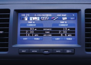
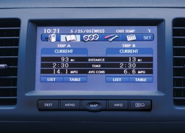
Dynamics Control operation indicator light ....... Vehicle Dynamics Control OFF indicator light ..... Security indicator light....................................... Select lever/gear position indicator..................... Turn signal indicator lights................................. High beam indicator light ................................... Cruise control indicator light.............................. Cruise control set indicator light ........................ Headlight indicator light ..................................... Front fog light indicator light (if equipped).......... Clock .................................................................. Multi function display ........................................ Outside temperature indicator ............................ Average fuel consumption ................................. Current fuel consumption .................................. Driving range on remaining fuel .........................
3-15
3-15
3-16
3-17
3-19
3-19
3-20
3-20
3-203-20
3-20
3-21
3-22
3-22
3-23
3-23
3-23
3-23
3-23
3-23
3-24
3-24
3-25
3-25
3-26
3-26Instruments and controls
Light control switch ........................................... 3-27
Headlights.......................................................... 3-27
High/low beam change (dimmer)......................... 3-28
Headlight flasher ................................................ 3-28
Daytime running light system ............................. 3-29
Turn signal lever ................................................ 3-29
Illumination brightness control ......................... 3-30
Front fog light switch (if equipped) .................. 3-30Wiper and washer.............................................. Windshield wiper and washer switches .............. Rear window wiper and washer switch
(Outback) ........................................................ Defogger and deicer.......................................... Mirrors ................................................................ Inside mirror...................................................... Auto-dimming mirror/compass (if equipped) ....... Outside mirrors ................................................. Tilt/telescopic steering wheel ........................... Horn....................................................................
3-31
3-323-34
3-34
3-36
3-36
3-36
3-38
3-38
3-39Ignition switch
WARNING
. Never turn the ignition switch to “LOCK” while the vehicle is being driven or towed because that will lock the steering wheel, preventing steering control. And when the engine is turned off, it takes a much greater effort than usual to steer.
. Before leaving the vehicle, al- ways remove the key from the ignition switch for safety and never allow an unattended child to remain in the vehicle. Failure to follow this procedure could result in injury to a child or others. Children could operate the power windows, the sunroof or other controls or even make the vehicle move.
CAUTION
Do not attach a large key holder or key case to either key. If it banged against your knees or hands while you are driving, it could turn the ignition switch from the “ON” posi-
if
tion to the “Acc” or “LOCK” posi- tion, thereby stopping the engine. Also, the key is attached to a keyholder or to a large bunch of other keys, centrifugal force may act on it as the vehicle moves, resulting in unwanted turning of the ignition switch.
The ignition switch has four positions: LOCK, Acc, ON and START.
Instruments and controls 3-3
. If the ignition switch will not move from the “LOCK” position to the “Acc” position, turn the steering wheel slightly to the left and right as you turn the ignition switch.
& LOCK The key can only be inserted or removed in this position. The ignition switch will lock the steering wheel when you remove the key. If turn the steering wheel slightly to the right and left as you turn the key.
turning the key is difficult,
NOTE . Keep the ignition switch in the “LOCK” position when the engine is not running. . Using electrical accessories for a long time with the ignition switch in the “ON” or “Acc” position can cause the battery to go dead.
The key can be turned from “Acc” to “LOCK” only when the key is pushed in while turning it (all models) and the select lever is in the “P” position (AT and CVT models).
– CONTINUED –
3-4 Instruments and controls
& Acc In this position the electrical accessories (radio, accessory power outlet, etc.) can be used.
& ON This is the normal operating position after the engine is started.
& START
CAUTION
Do not turn the ignition switch to the “START” position while the engine is running.
The engine is started in this position. The starter cranks the engine to start it. When the key is released (after the engine has started), the key automatically returns to the “ON” position. If the engine does not start with your registered key, pull out the key once (at this time, the security indicator light will blink), wait least 10 seconds, reinsert the key in the ignition switch and then try to start the engine again. NOTE The engine may not start in the follow- ing cases:
for at
. The key grip is touching another key or a metallic key holder.
. The key is near another key that contains an immobilizer transponder. . The key is near or touching another transmitter.
& Key reminder chime The reminder chime sounds when the driver’s door opens and the key is in the “LOCK” or “Acc” positions. The chime stops when the ignition switch is turned to the “ON” position or the key is removed from the ignition switch.
& Ignition switch light For easy access to the ignition switch in the dark, the ignition switch light illumi- nates when driver’s door is opened or when the driver’s door is unlocked using the remote keyless entry transmitter.
The light remains illuminated for approxi- mately 30 seconds and gradually turns off under the following conditions. . When the driver’s door is closed . When the doors are unlocked using the remote keyless entry transmitter
The light gradually turns off under the following conditions. . When the ignition switch is turned to the “ON” position . When the doors are locked using the remote keyless entry transmitter
Hazard warning flasher
Meters and gauges
NOTE Liquid-crystal displays are used in some of the meters and gauges in the combination meter. You will find their indications hard to see if you wear polarized glasses.
& Combination meter illumina-
tion
the various parts of
When the ignition switch is turned to the “ON” position, the combination meter are illuminated in the following sequence. 1. Warning lights, indicator lights, meter needles, gauge needles, odometer and trip meter back light illuminate. 2. Meter needles and gauge needles each show MAX position. 3. Meter needles and gauge needles each show MIN position. 4. Dials and indicators in meters and gauges light up. 5. Regular illumination (for driving) be- gins.
The hazard warning flasher is used to warn other drivers when you have to park your vehicle under emergency conditions. The hazard warning flasher works with the ignition switch in any position.
To turn on the hazard warning flasher, press the hazard warning button on the instrument panel. To turn off the flasher, press the button again. NOTE When the hazard warning flasher is on, the turn signals do not work.
Instruments and controls 3-5
NOTE The above sequence of operations may not take place if you quickly turn the ignition switch to start the engine. This is not a malfunction. & Canceling the function for meter/gauge needle move- ment upon turning on the ignition switch
It is possible to activate or deactivate the movement of the meter needles and gauge needles that takes place when the ignition switch is turned to the “ON” position. 1. Turn the ignition switch to the “LOCK” or “Acc” position. 2. Press the trip knob to show “
” or
– CONTINUED –
3-6 Instruments and controls
” on the trip meter display.
“ The display can be switched as shown in the following illustration by pressing the trip knob.
needles when the ignition switch is in the “ON” position. Change the setting when the ignition switch is in the “LOCK” or “Acc” position. & Speedometer The speedometer shows the vehicle speed.
& Odometer
seconds of illumination of the odometer/ trip meter, the odometer/trip meter will turn off. Also, if you open and close the driver’s door within 10 seconds of illumination of the odometer/trip meter, the odometer/trip meter will turn off.
& Double trip meter
*1: “
” or “
” and “
” cannot be displayed when the ignition switch is in the “ON” position.
” or “
*2: MT models only
3. To change the current setting, press the trip knob for at least 2 seconds.
: Activated : Deactivated
NOTE . Your vehicle’s initial movement the meter/gauge needles setting of has been set for activation “ ” at the time of shipment from the factory. . It is not possible to change the initial movement setting of the meter/gauge
This meter displays the odometer when the ignition switch is in the “ON” position. The odometer shows the total distance that the vehicle has been driven.
If you press the trip knob when the ignition switch is in the “LOCK” or “Acc” position, the odometer/trip meter will light up. If you do not press the trip knob within 10
This meter displays the two trip meters when the ignition switch is in the “ON” position. The trip meter shows the distance that the vehicle has been driven since you last set it to zero.
If you press the trip knob when the ignition switch is in the “LOCK” or “Acc” position, the odometer/trip meter will light up. It is
possible to switch between the A trip meter and B trip meter indications while the odometer/trip meter is lit up. If you do not press the trip knob within 10 seconds of illumination of the odometer/trip meter, the odometer/trip meter will turn off. Also, if you open and close the driver’s door within 10 seconds of illumination of the odometer/trip meter, the odometer/trip meter will turn off.
The display can be switched as shown in the following illustration by pressing the trip knob.
*1: “
” or “
” and “
” cannot be displayed when the ignition switch is in the “ON” position.
” or “
*2: MT models only
To set the trip meter to zero, select the A trip or B trip meter by pressing the knob and keep the knob pressed for more than 2 seconds.
CAUTION
To ensure safety, do not attempt to change the function of the indicator during driving, as an accident could result.
NOTE If the connection between the combina- tion meter and battery is broken for any reason such as vehicle maintenance or fuse replacement, the data recorded on the trip meter will be lost.
& Tachometer The tachometer shows the engine speed in thousands of revolutions per minute.
CAUTION
Do not operate the engine with the pointer of the tachometer in the red zone. In this range, fuel injection will be cut by the engine control module to protect the engine from overrev- ving. The engine will resume run- ning normally after the engine speed is reduced below the red zone.
Instruments and controls 3-7
NOTE To protect the engine while the select lever is in the “P” or “N” position (for AT and CVT models) or the shift lever is in the neutral position (for MT models), the engine is controlled so that the engine speed may not become too high even if the accelerator pedal is pressed hard.
& Fuel gauge
1)
Low fuel warning light
The fuel gauge shows the approximate amount of fuel remaining in the tank. When the ignition switch is in the “LOCK” or “Acc” position, the fuel gauge shows “E” even if the fuel tank contains fuel.
– CONTINUED –
3-8 Instruments and controls
indicate the amount of
The gauge may move slightly during braking, turning or acceleration due to fuel level movement in the tank. If you press the trip knob while the ignition switch is in the “LOCK” or “Acc” position, the fuel gauge’s dial will light up and the needle will fuel remaining in the tank. If, while the fuel gauge needle is indicating the amount of fuel remaining in the tank, you (a) do not press the trip knob for 10
seconds or (b) open and close the driver’s door, the fuel gauge needle will drop to the “E” position and the dial and needle will turn off. NOTEYou will see the “
” sign in the fuel
gauge. This indicates that the fuel filler door (lid) is located on the right side of the vehicle. ! Low fuel warning light The low fuel warning light illuminates when the fuel tank is nearly empty. It only operates when the ignition switch is in the “ON” position. When this light illuminates, fill the fuel tank immediately.
CAUTION
Promptly put fuel in the tank when- ever the low fuel warning light illuminates. Engine misfires as a result of an empty tank could cause damage to the engine.
NOTE . The low fuel warning light illumi- nates when the remaining amount of fuel in the tank has reached approxi- mately 2.6 US gal (10 liters, 2.2 Imp. gal). . The low fuel warning light does not turn off unless the tank is replenished up to a fuel quantity of approximately 4.0 US gal (15 liters, 3.3 Imp gal).
& ECO gauge
1) U.S.-spec. models 2) Except U.S.-spec. models
The ECO gauge shows the difference between the average rate of fuel con- sumption and the current fuel consumption. Using the average rate of fuel consumption since the trip meter was last reset, the indicator needle behaves as described in the following items.
rate of
than the average rate of
U.S.-spec. models: If the current rate of fuel consumption is lower fuel consumption, the indicator needle points to the “+” side. If the current rate of fuel consumption is higher than the average rate of the indicator needle points to the “−” side. When the
fuel consumption,
indicator needle is pointing to the “+” side, it indicates fuel-efficient driving.
fuel consumption,
than the average rate of
Except U.S.-spec. models: If the current rate of fuel consumption is lower fuel consumption, the indicator needle points to the “−” side. If the current rate of fuel consumption is higher than the average rate of the indicator needle points to the “+” side. When the indicator needle is pointing to the “−” side, it indicates fuel-efficient driving. NOTE . The ECO gauge shows only an approximate indication. . After resetting the trip meter, the average rate of fuel consumption is not shown until driving 0.6 mile (1 km). Until that time, the ECO gauge does not operate.
Warning and indicator lights
Several of the warning and indicator lights illuminate momentarily and then go out when the ignition switch is initially turned to the “ON” position. This permits check- ing the operation of the bulbs. Apply the parking brake and turn the ignition switch to the “ON” position. The following lights illuminate:
: Seatbelt warning light
(The seatbelt warning light only when the driver seatbelt.) : Front passenger’s seatbelt warning
turns off fastens the
light (The seatbelt warning light turns off only when the front seat passenger fastens the seatbelt.)
: SRS airbag system warning light
: CHECK ENGINE warning light/Mal-
function indicator lamp
: Coolant temperature high warning light
: Charge warning light
: Oil pressure warning light
: Engine low oil level warning light
Instruments and controls 3-9
: AT OIL TEMP warning light
(AT and CVT models)
: ABS warning light
: Vehicle Dynamics Control warning light/Vehicle Dynamics Control opera- tion indicator light
: Vehicle Dynamics Control OFF indica-
tor light
: Brake system warning light
: Hill Holder indicator light
: All-Wheel Drive warning light (AT and CVT models)
: Low tire pressure warning light
(U.S.-spec. models)
ON /
: Front passenger’s frontal airbag
ON indicator light
: Front passenger’s frontal airbag
OFF indicator light
: Low fuel warning light
: Door open warning light
: Door open indicator light
: Cruise control indicator light
: Cruise control set indicator light
: Windshield washer fluid warning light
: Select lever/gear position indicator
– CONTINUED –
3-10 Instruments and controls
If any lights fail to illuminate, it indicates a burned-out bulb or a malfunction of the corresponding system. Consult your authorized SUBARU dealer for repair. & Seatbelt warning light
and chime
Your vehicle is equipped with a seatbelt warning device at the driver’s and front passenger’s seat, as required by current safety standards. With the ignition switch turned to the “ON” position, this device reminds the driver and front passenger to fasten their seat- belts by the warning lights in the locations indicated in the following illustration and a chime.
Driver’s warning light
The warning light(s) for unfastened seatbelt(s) will alternate between steady illumination and flashing at 15-second intervals. The chime will not sound. – At speeds higher than approxi- mately 9 mph (15 km/h) The warning light(s) for unfastened seatbelt(s) will alternate between flashing and steady illumination at 15-second intervals and the chime will sound while the warning light(s) is/are flashing.
time, however,
. It is possible to cancel the warning operation that follows the 6-second warning after turning ON the ignition switch. When the ignition switch is turned ON next the the warning complete sequence of operation resumes. For further details about canceling the warning operation, please contact your SUBARU dealer. there is no passenger on the front If passenger’s seat, the seatbelt warning device for the front passenger’s seat will be deactivated. The front passenger’s occupant detection system monitors whether or not there is a passenger on the front passenger’s seat. Observe the following precautions. Failure to do so may prevent the device from functioning correctly or cause the device to fail.
Front passenger’s warning light ! Operation If the driver and/or front passenger have/ has not yet fastened the seatbelt(s) when the ignition switch is turned to the “ON” position, the seatbelt warning light(s) will flash for 6 seconds, the seatbelt(s) is/are unfastened. the dri- ver’s seatbelt is not fastened, a chime will also sound simultaneously. NOTE . If the driver’s and/or front passen- ger’s seatbelt(s) are/is still not fastened 6 seconds later, the seatbelt warning device operates as follows according to the vehicle speed.
to warn that
If
– At speeds lower than approxi- mately 9 mph (15 km/h)
. Do not install any accessory such as a table or TV onto the seatback. . Do not store a heavy load in the seatback pocket. . Do not allow the rear seat occupant to place his/her hands or legs on the front passenger’s seatback, or allow him/her to pull the seatback. . Do not use front seats with their back- ward-forward position and seatback not being locked into place securely. If any of them are not locked securely, adjust them again. For adjusting procedure, refer to “Manual seat” F1-3 (models equipped with manual seats only).
If the seatbelt warning device for the front passenger’s seat does not function cor- rectly (e.g., it is activated even when the front passenger’s seat is empty or it is deactivated even when the front passen- ger has not fastened his/her seatbelt), take the following actions. . Ensure that no article is placed on the seat other than a child restraint system and its child occupant. . Ensure that there is no article left in the seatback pocket. . Ensure that the backward-forward po- sition and seatback of front passenger’s seat are locked into place securely by moving the seat back and forth. (Models
equipped with manual seats only)
If still the seatbelt warning device for front passenger’s seat does not function cor- rectly after taking relevant corrective ac- tions described above, immediately con- tact your SUBARU dealer for an inspec- tion. & SRS airbag system
warning light
When the ignition switch is turned to the “ON” position, the SRS airbag system warning light will illuminate for approxi- mately 6 seconds and turn off. This shows the SRS frontal airbag and SRS side airbag and SRS curtain airbag and seat- belt pretensioners are in normal operation.
WARNING
If the warning light exhibits any of the following conditions, there may be a malfunction in the seatbelt pretensioners and/or SRS airbag system. Immediately take your vehi- cle to your nearest SUBARU dealer to have the system checked. Unless checked and properly repaired, the seatbelt pretensioners and/or SRS airbags will operate improperly (e.g. SRS airbags may inflate in a very
Instruments and controls 3-11
minor collision or not inflate in a severe collision), which may in- crease the risk of injury. . Flashing or flickering of the warn-
ing light
. No illumination of
the warning light when the ignition switch is first turned to the “ON” position the
. Continuous illumination of
warning light
. Illumination of the warning light
while driving
– CONTINUED –
3-12 Instruments and controls
& Front passenger’s frontal
airbag ON and OFF indica- tors
ON /
: Front passenger’s frontal airbag ON indicator
: Front passenger’s frontal airbag OFF indicator
The front passenger’s frontal airbag ON and OFF indicators show you the status of the front passenger’s SRS frontal airbag. The indicators are located next to the clock in the center portion of the dash- board. When the ignition switch is turned to the “ON” position, both the ON and OFF indicators illuminate for 6 seconds during which time the system is checked. Follow- ing the system check, both indicators turn off for 2 seconds. After that, one of the
indicators illuminates depending on the status of the front passenger’s SRS frontal airbag determined by the SUBARU ad- vanced frontal airbag system monitoring. If the front passenger’s SRS frontal airbag is activated, the passenger’s frontal airbag ON indicator will illuminate while the OFF indicator will remain off. If the front passenger’s SRS frontal airbag the passenger’s frontal is deactivated, airbag ON indicator will remain off while the OFF indicator will illuminate. With the ignition switch turned to the “ON” position, if both the ON and OFF indica- tors remain illuminated or off simulta- neously even after the system check the system is malfunctioning. period, Contact your SUBARU dealer immedi- ately for an inspection. & CHECK ENGINE warn-
ing light/Malfunction indicator lamp
CAUTION
If the CHECK ENGINE warning light/ malfunction indicator lamp illumi- nates while you are driving, have your vehicle checked/repaired by your SUBARU dealer as soon as possible. Continued vehicle opera-
tion without having the emission control system checked and re- paired as necessary could cause serious damage, which may not be covered by your vehicle’s warranty.
If this light illuminates steadily or blinks while the engine is running, it may indicate that there is a problem or potential problem somewhere in the emission con- trol system. ! If the light illuminates steadily If the light illuminates steadily while driving or does not turn off after the engine starts, an emission control system malfunction has been detected. You should have your vehicle checked by an authorized SUBARU dealer immedi- ately. NOTE This light also illuminates when the fuel filler cap is not tightened until it clicks. If you have recently refueled your vehicle, the cause of the CHECK ENGINE warning light/malfunction indicator lamp coming on could be a loose or missing fuel filler cap. Remove the cap and retighten it until it clicks. Make sure nothing is interfering with the sealing of the cap. Tightening the cap will not make the CHECK ENGINE
the light
warning light/malfunction indicator lamp turn off immediately. It may take several driving trips. If the light does not turn off, take your vehicle to your authorized SUBARU dealer immediately. ! If the light is blinking If is blinking while driving, an engine misfire condition has been de- tected which may damage the emission control system. To prevent serious damage to the emis- sion control system, you should conform to the following instructions. . Reduce vehicle speed. . Avoid hard acceleration. . Avoid steep uphill grades. . Reduce the amount of cargo, if possi- ble. . Stop towing a trailer as soon as possible.
The CHECK ENGINE warning light/mal- function indicator lamp may stop blinking and illuminate steadily after several driv- ing trips. You should have your vehicle checked by an authorized SUBARU deal- er immediately.
& Coolant temperature
low indicator light/Cool- ant temperature high warning light
CAUTION
if
. After turning the ignition switch to the “ON” position, this indicator light/warning light be- haves under any of the following conditions, the electrical system may be malfunctioning. Contact your SUBARU dealer immedi- ately for an inspection. – It remains blinking in RED. – It remains illuminated in RED
for more than 2 seconds.
– It remains blinking in RED and
BLUE alternately.
. While driving,
if
this indicator light/warning light behaves under any of the following conditions, take the specified appropriate measure listed below. – Blinking in RED:
Decelerate the vehicle. After the blinking RED light turns off, you can drive the vehicle normally.
– Illuminated in RED:
Instruments and controls 3-13
Safely stop the vehicle as soon as possible, and refer to the emergency steps for the case of engine overheating. After that, have the system checked by your nearest SUBARU dealer. Refer to “En- gine overheating” F9-12.
– Blinking in RED and BLUE
alternately: The electrical system may be malfunctioning. Contact your SUBARU dealer for an inspec- tion.
temperature low indicator temperature high warning
This coolant light/coolant light has the following three functions. . Illumination in BLUE indicates insuffi- cient warming up of the engine . Blinking in RED indicates that engine is close to overheating . Illumination in RED indicates overheat- ing condition of the engine
the
For the system check, this indicator light/ warning light illuminates in RED for approximately 2 seconds when the igni- tion switch is turned to the “ON” position. After that, this indicator light/warning light changes to BLUE and maintains illumina- tion in BLUE. This BLUE illuminated light
– CONTINUED –
3-14 Instruments and controls
turns off when the engine is warmed up sufficiently.
the engine coolant
If temperature in- creases over the appropriate range, the indicator light/warning light blinks in RED. At this time, decelerate the vehicle. After the blinking RED light turns off, you can drive the vehicle normally. However, if the indicator light/warning light often blinks in RED, the electrical system may be mal- functioning. Contact your SUBARU dealer for an inspection.
the engine coolant
If temperature in- creases further, the indicator light/warning light illuminates in RED continuously. At this time, the engine may be overheating. Safely stop the vehicle as soon as possible, and refer to the emergency steps for the case of engine overheating. to “Engine overheating” F9-12. Refer After that, have the system checked by your nearest SUBARU dealer. NOTE If the engine is restarted after a certain driving condition, this indicator light/ warning light may illuminate in RED. However, this is not a malfunction if the indicator light/warning light turns off after a short time.
& Charge warning light If this light illuminates when the engine is running, it may indicate that the charging system is not working properly.
If the light illuminates while driving or does not turn off after the engine starts, stop the engine at the first safe opportunity and the belt check the alternator belt. is loose, broken or if is in good condition but the light remains illuminated, contact your nearest SUBARU dealer immediately. & Oil pressure warning
If the belt
light
CAUTION
Do not operate the engine with the oil pressure warning light on. This may cause serious engine damage.
If this light illuminates when the engine is running, it may indicate that the engine oil pressure is low and the lubricating system is not working properly. If the light illuminates while driving or does not turn off after the engine starts, stop the engine at the first safe opportunity and check the engine oil level. If the oil level is low, add oil immediately. If the engine oil is
at the proper level but the light remains illuminated, contact your nearest SUBARU dealer immediately. & Engine low oil level
warning light The engine low oil level warning light illuminates when the ignition switch is turned to the “ON” position and turns off after approximately 2 seconds. This light also illuminates when the engine oil level decreases to the lower limit. The illuminating conditions and remaining oil level are shown in the following items. 2.5 L models: . when the ignition switch is in the “ON” position but the engine is not running: approximately 1.9 US qt (1.8 liters, 1.6
Imp qt) . while the engine is running: approxi- mately 3.2 US qt (3.0 liters, 2.6 Imp qt)3.6 L models: . when the ignition switch is in the “ON” position but the engine is not running: approximately 4.0 US qt (3.8 liters, 3.3
Imp qt) . while the engine is running: approxi- mately 5.6 US qt (5.3 liters, 4.7 Imp qt)the engine low oil
If level warning light illuminates while driving, park the vehicle
level
location, and then level. When the is not within the normal if necessary.
at a safe and level check the engine oil engine oil range, refill with engine oil Refer to “Engine oil” F11-12. If the warning light does not turn off after refilling with engine oil or the warning light illuminates even though the engine oil level is within the normal range, have the system checked by a SUBARU dealer. NOTE . The engine low oil level warning light will not turn off immediately even if you replace or add engine oil. It will turn off only when the vehicle is idling and the engine is warmed up comple- tely. . When the vehicle is considerably inclined on an uphill or steep slope, the warning light may illuminate tempora- rily due to the movement of engine oil in the engine.
& AT OIL TEMP warning
light (AT and CVT mod- els)
The AT oil temperature warning light “AT OIL TEMP” illuminates when the ignition switch is turned to the “ON” position and turns off after approximately 2 seconds.
If this light illuminates when the engine is running, it may indicate that the transmis- sion fluid temperature is too hot. If the light illuminates while driving, im- mediately stop the vehicle in a safe place and let the engine idle until the warning light turns off. ! Transmission control system warn-
ing
the engine has started,
If the “AT OIL TEMP” warning light flashes after it may indicate that the transmission control system is not working properly. Contact your nearest SUBARU dealer for service immediately. & Low tire pressure
warning light (U.S.-spec. models)
When the ignition switch is turned to the “ON” position, the low tire pressure warn- ing light will illuminate for approximately 2
seconds to check that the tire pressure monitoring system (TPMS) is functioning properly. If there is no problem and all tires are properly inflated, the light will go out. Each tire, including the spare (if provided), should be checked monthly when cold and inflated to the inflation pressure recommended by the vehicle manufac- turer on the vehicle placard or tire inflationInstruments and controls 3-15
pressure label. (If your vehicle has tires of a different size than the size indicated on the vehicle placard or tire inflation pres- sure label, you should determine the proper those tires.)
tire inflation pressure for
As an added safety feature, your vehicle has been equipped with a tire pressure monitoring system (TPMS) that illuminates a low tire pressure telltale when one or more of your tires is significantly under- inflated. Accordingly, when the low tire pressure telltale illuminates, you should stop and check your tires as soon as possible, and inflate them to the proper pressure. Driving on a significantly under- inflated tire causes the tire to overheat and can lead to tire failure. Under-inflation also reduces fuel efficiency and tire tread life, and may affect the vehicle’s handling and stopping ability. the TPMS is not a Please note that tire maintenance, substitute for proper is the driver’s responsibility to and it maintain correct tire pressure, even if under-inflation has not reached the level to trigger illumination of the TPMS low tire pressure telltale. Your vehicle has also been equipped with a TPMS malfunction indicator to indicate when the system is not operating properly. The TPMS malfunction indicator is com- – CONTINUED –
3-16 Instruments and controls
bined with the low tire pressure telltale. When the system detects a malfunction, the telltale will flash for approximately one minute and then remain continuously illuminated. This sequence will continue upon subsequent vehicle start-ups as long as the malfunction exists. When the malfunction indicator is illuminated, the system may not be able to detect or signal low tire pressure as intended. TPMS malfunctions may occur for a variety of reasons, including the installation of re- placement or alternate tires or wheels on the vehicle that prevent the TPMS from functioning properly. Always check the TPMS malfunction telltale after replacing one or more tires or wheels on your vehicle to ensure that the replacement or alternate tires and wheels allow the TPMS to continue to function properly. Should the warning light illuminate stea- dily after blinking for approximately one minute, have the system inspected by your nearest SUBARU dealer as soon as possible.
WARNING
this light does not
If illuminate briefly after the ignition switch is turned ON or the light illuminates steadily after blinking for approxi- mately one minute, you should have
this light still
your Tire Pressure Monitoring Sys- tem checked at a SUBARU dealer as soon as possible. If this light illuminates while driving, never brake suddenly and keep driving straight ahead while gradu- ally reducing speed. Then slowly pull off the road to a safe place. Otherwise an accident involving serious vehicle damage and serious personal injury could occur. If illuminates while driving after adjusting the tire pres- sure, a tire may have significant damage and a fast leak that causes the tire to lose air rapidly. If you have a flat tire, replace it with a spare tire as soon as possible. When a spare tire is mounted or a wheel rim is replaced without the original pressure sensor/transmitter being transferred, the Low tire pres- sure warning light will illuminate steadily after blinking for approxi- mately one minute. This indicates the TPMS is unable to monitor all four road wheels. Contact your SUBARU dealer as soon as possible for tire and sensor replacement and/ or system resetting. the light illuminates steadily after blinking for approximately one minute,
If
promptly contact a SUBARU dealer to have the system inspected.
CAUTION
The tire pressure monitoring system is NOT a substitute for manually checking tire pressure. The tire pressure should be checked peri- odically (at least monthly) using a tire gauge. After any change to tire pressure(s), the tire pressure mon- itoring system will not re-check tire inflation pressures until the vehicle is first driven more than 20 mph (32
km/h). After adjusting the tire pres- sures, increase the vehicle speed to at least 20 mph (32 km/h) to start the TPMS re-checking of the tire infla- tion pressures. If the tire pressures are now above the severe low pressure threshold, the low tire pressure warning light should turn off a few minutes later. Therefore, be sure to install the specified size for the front and rear tires.& ABS warning light The ABS warning light illuminates when the ignition switch is turned to the “ON”
position and turns off after approximately 2
seconds. This is an indication that the ABS system is working properly.CAUTION
If the warning light behaves as follows, the ABS system may not work properly. When the warning light illuminates, the ABS function shuts down; how- ever, the conventional brake system continues to operate normally. . The warning light does not illu- minate when the ignition switch is turned to the “ON” position.
. The warning light
illuminates when the ignition switch is turned to the “ON” position, but it does not turn off even when the vehicle speed exceeds approxi- mately 8 mph (12 km/h).
. The warning light illuminates dur-
ing driving. If any of these conditions occur, have the ABS system repaired at the first available opportunity by your SUBARU dealer.
The ABS warning light
illuminates to-
gether with the brake system warning light the EBD system malfunctions. For if further details of the EBD system mal- function warning, refer to “Brake system warning light” F3-17. NOTE If the warning light behavior is as described in the following conditions, the ABS system may be considered normal. . The warning light illuminates right after the engine is started but turns off immediately, remaining off. . The warning light remains illumi- nated after the engine has been started, but it turns off when the vehicle speed reaches approximately 8 mph (12
km/h). . The warning light illuminates during driving, but it turns off immediately and remains off. When driving with an insufficient battery voltage such as when the engine is jump started, the ABS warning light may illumi- nate. This is due to the low battery voltage and does not indicate a malfunction. When the battery becomes fully charged, the light will turn off.Instruments and controls 3-17
& Brake system warning light
WARNING
. Driving with the brake system warning light on is dangerous. This indicates your brake system may not be working properly. If the light remains illuminated, have the brakes inspected by a SUBARU dealer immediately.
. If at all in doubt about whether the brakes are operating prop- erly, do not drive the vehicle. Have your vehicle towed to the nearest SUBARU dealer for re- pair.
. If the brake system warning light flashes, the electronic parking brake system may be malfunc- tioning. Immediately stop your vehicle in a safe location, use tire stops under the tires to prevent the vehicle from moving and contact your SUBARU deal- er. For details, refer to “Electro- nic parking brake” F7-34.
– CONTINUED –
3-18 Instruments and controls
NOTE . When the ignition switch is turned to the “LOCK” position with the electronic parking brake applied, the brake sys- tem warning light remains illuminated for approximately 30 seconds and then turns off. . When the electronic parking brake switch is pressed to apply the electro- nic parking brake while the ignition switch is in the “LOCK” position, the brake system warning light illuminates, remains illuminated for approximately 30 seconds and then turns off. . Even if the brake system warning light flashes, if the warning light beha- vior is as described in the following examples, the electronic parking brake system is not malfunctioning.
– The warning light turns off when the electronic parking brake is ap- plied or released. – The warning light turns off when the ignition switch is turned to the “ON” position again.
. The brake system warning light may flash when the engine is started im- mediately after the electronic parking brake is applied or released. However, the electronic parking brake system is not malfunctioning if the warning light turns off after the electronic parking
brake is applied or released after that. . The brake system warning light may flash after the electronic parking brake is frequently applied and released. However, the electronic parking brake system is not malfunctioning if the light turns off for a short period of time. This light has the following functions: ! Parking brake warning The light illuminates with the parking brake applied while the ignition switch is in the “ON” position. It turns off when the parking brake is fully released. ! Brake fluid level warning This light illuminates when the brake fluid level has dropped to near the “MIN” level of the brake fluid reservoir with the ignition switch in the “ON” position and with the parking brake fully released.
If the brake system warning light should illuminate while driving (with the parking brake fully released and with the ignition switch positioned in “ON”), it could be an indication of leaking of brake fluid or worn brake pads. immediately stop the vehicle at the nearest safe place and check the brake fluid level. If the fluid is below the “MIN” mark in the level reservoir, do not drive the vehicle. Have the vehicle towed to the nearest SUBARU
this occurs,
If
dealer for repair. ! Electronic Brake Force Distribution
(EBD) system warning
The brake system warning light also illuminates if a malfunction occurs in the EBD system. In that event, it illuminates together with the ABS warning light. The EBD system may be malfunctioning if the brake system warning light and ABS warning light illuminate simultaneously during driving. Even if the EBD system fails, the conven- tional braking system will still function. However, the rear wheels will be more prone to locking when the brakes are applied harder than usual and the vehi- cle’s motion may therefore become some- what harder to control. If the brake system warning light and ABS warning light illuminate simultaneously, take the following steps: 1. Stop the vehicle in the nearest safe, flat place. 2. Shut down the engine, then restart it. 3. Release the parking brake. If both warning lights turn off, the EBD system may be malfunctioning. Drive carefully to the nearest SUBARU dealer and have the system inspected. 4. If both warning lights illuminate again and remain illuminated after the engine
has been restarted, shut down the engine again, apply the parking brake, and check the brake fluid level. If the brake fluid level is not below the 5. “MIN” mark, the EBD system may be malfunctioning. Drive carefully to the nearest SUBARU dealer and have the system inspected. 6. is below the “MIN” mark, DO NOT drive the vehicle. Instead, have the vehicle towed to the nearest SUBARU dealer for repair.
the brake fluid level
If
! Electronic parking brake system
warning
If
The brake system warning light flashes when the electronic parking brake system is malfunctioning. the warning light flashes, promptly park in a safe location as soon as possible and contact your SUBARU dealer. The brake system warning light remains illuminated when the parking brake cannot be released even if the parking brake switch is pulled. For details, to “Electronic parking brake” F7-34. ! Parking brake apply inhibit warning The brake system warning light flashes for 10 seconds and a chirp sound will be heard if the parking brake switch is operated when the parking brake cannot
refer
be applied. ! Frequent operation warning The brake system warning light flashes for 20 seconds and a chirp sound will be heard if the parking brake switch is operated too frequently. In this case, the operation of the parking brake switch is restricted to protect the electronic parking brake system. NOTE Wait until the warning light turns off. ! Emergency released warning The brake system warning light flashes when the parking brake is automatically released in case of an emergency. & Hill Holder indicator
light
WARNING
If the Hill Holder indicator light does not illuminate even when the Hill Holder switch is pressed to activate the Hill Holder function, the electro- nic parking brake system may be malfunctioning. Immediately stop the vehicle in a safe location and contact your SUBARU dealer.
Instruments and controls 3-19
The light illuminates when the ignition switch is turned to the “ON” position and turns off after approximately 2 seconds.
The light illuminates when the Hill Holder switch is pressed to activate the Hill Holder function. & Low fuel warning
light
The low fuel warning light illuminates when the tank is nearly empty approxi- mately 2.6 US gal (10.0 liters, or 2.2 Imp gal). It only operates when the ignition switch is in the “ON” position. NOTE This light does not turn off unless the tank is replenished up to an internal fuel quantity of approximately 3.7 US gal (14 liters, 3.1 Imp gal).
CAUTION
Promptly put fuel in the tank when- ever the low fuel warning light illuminates. Engine misfires as a result of an empty tank could cause damage to the engine.
– CONTINUED –
3-20 Instruments and controls
& Door open warning
light
& Windshield washer fluid warning light
When the ignition switch is in the “ON” position, the door open warning light illuminates for approximately 2 seconds and then turns off. The door open warning light illuminates if any door, the rear gate (Outback) or trunk fully closed. This lid (Legacy) function is effective even if the ignition switch is in the “LOCK” or “Acc” position or the key is removed from the ignition switch.
is not
Always make sure this light is not illumi- nated before you start to drive. & Door open indicator
light
the doors,
When any of the rear gate (Outback) or the trunk lid (Legacy) is not fully closed, the door open indicator light illuminates. This function is effective even if the ignition switch is in the “LOCK” or “Acc” position or the key is removed from the ignition switch. The open door is indicated by the corre- sponding part of the door open warning light.
Always make sure this light is not illumi- nated before you start to drive.
This light illuminates when the fluid level in the windshield washer fluid tank de- creases to the lower limit (approximately 0.6 US qt, 0.6 liter, 0.5 Imp qt). & All-Wheel Drive
warning light (AT and CVT models)
WARNING
If
Continued driving with the AWD warning light flashing can lead to powertrain damage. the AWD warning light flashes, promptly park in a safe place then check whether all four tires are the same diameter and whether any of the tires has a puncture or has lost air pressure for some other reason.
The All-Wheel Drive warning light illumi- nates when the ignition switch is turned to the “ON” position and turns off after the engine has started. ! For AT models This light flashes if the vehicle is driven with tires of different diameters fitted on its wheels or with the air pressure exces-
sively low in any of its tires. ! For CVT models This light illuminates when All-Wheel Drive is disengaged and the drive me- chanism is switched to Front Wheel Drive for maintenance or similar purposes. This light flashes if the vehicle is driven with tires of different diameters fitted on its wheels or with the air pressure exces- sively low in any of its tires. & Vehicle Dynamics
Control warning light/ Vehicle Dynamics Con- trol operation indicator light The light illuminates when the ignition switch is turned to the “ON” position and turns off several seconds after the engine has started. This lighting pattern indicates that the Vehicle Dynamics Control system is operating normally. ! Vehicle Dynamics Control warning
light
CAUTION
The Vehicle Dynamics Control sys- tem provides its ABS control through the electrical circuit of the
ABS system. Accordingly, if the ABS is inoperative, the Vehicle Dynamics Control system becomes unable to provide ABS control. As a result, the