- 2006 Subaru Legacy Owners Manuals
- Subaru Legacy Owners Manuals
- 2004 Subaru Legacy Owners Manuals
- Subaru Legacy Owners Manuals
- 2008 Subaru Legacy Owners Manuals
- Subaru Legacy Owners Manuals
- 2005 Subaru Legacy Owners Manuals
- Subaru Legacy Owners Manuals
- 2007 Subaru Legacy Owners Manuals
- Subaru Legacy Owners Manuals
- 2000 Subaru Legacy Owners Manuals
- Subaru Legacy Owners Manuals
- 2003 Subaru Legacy Owners Manuals
- Subaru Legacy Owners Manuals
- 2012 Subaru Legacy Owners Manuals
- Subaru Legacy Owners Manuals
- 2001 Subaru Legacy Owners Manuals
- Subaru Legacy Owners Manuals
- 2010 Subaru Legacy Owners Manuals
- Subaru Legacy Owners Manuals
- 2011 Subaru Legacy Owners Manuals
- Subaru Legacy Owners Manuals
- 2009 Subaru Legacy Owners Manuals
- Subaru Legacy Owners Manuals
- 2002 Subaru Legacy Owners Manuals
- Subaru Legacy Owners Manuals
- Download PDF Manual
-
– CONTINUED – 1-45
UG1090BA
Seat, seatbelt and SRS airbags
latch the hook onto the top tether anchor and tighten the top tether. See the “Top tether anchorages” for ad- ditional instructions.
(cid:132) Installing a booster seat
(cid:121) Child restraint systems and seatbelts can be- come hot in a vehicle that has been closed up in sunny weather; they could burn a small child. Check the child restraint system before you place a child in it. (cid:121) Do not leave an unsecured child restraint system in your vehicle. Unsecured child re- straint systems can be thrown around inside of the vehicle in a sudden stop, turn or accident; it can strike and injure vehicle occupants as well as result in serious injuries or death to the child.
When you install a child restraint system, fol- low the manufacturer’s instructions supplied with it. After installing the child restraint sys- tem, check to ensure that it is held securely in position. If it is not held tight and secure, the danger of your child suffering personal injury in
UG1094BA
9. To remove the child restraint system, press the re- lease button on the seatbelt buckle and allow the belt to retract completely. The belt will return to the ELR mode. NOTE When the child restraint system is no longer in use, remove it and restore the ELR function of the retractor. That function is restored by allowing the seatbelt to retract fully.
1-46
the event of an accident may be increased.
Seat, seatbelt and SRS airbags
UB1128BA
4. To remove the booster seat, press the release but- ton on the seatbelt buckle and allow the belt to retract.
UB1152BA
1. Place the booster seat in the rear seating position and sit the child on it. The child should sit well back on the booster seat. 2. Run the lap and shoulder belt through or around the booster seat and the child following the instruc- tions provided by its manufacturer. 3. Insert the tongue plate into the buckle until you hear a click. Take care not to twist the seatbelt. Make sure the shoulder belt is positioned across the center of child’s shoulder and that the lap belt is posi- tioned as low as possible on the child’s hips.
(cid:121) Never use a belt that is twisted or reversed. In an accident, this can increase the risk or sever- ity of injury to the child. (cid:121) Never place the shoulder belt under the child’s arm or behind the child’s back. If an ac- cident occurs, this can increase the risk or se- verity of injury to the child. (cid:121) The seatbelt should fit snugly in order to pro- vide full restraint. Loose fitting belts are not as – CONTINUED – 1-47
Seat, seatbelt and SRS airbags
effective in preventing or reducing injury. (cid:121) Place the lap belt as low as possible on the child’s hips. A high-positioned lap belt will in- crease the risk of sliding under the lap belt and of the lap belt sliding up over the abdomen, and both can result in serious internal injury or death. (cid:121) Make sure the shoulder belt is positioned across the center of child’s shoulder. Placing the shoulder belt over the neck may result in neck injury during sudden braking or in a colli- sion.
(cid:132) Installation of child restraint systems by use of lower and tether anchorages (LATCH)
(cid:121) Child restraint systems and seatbelts can be- come hot in a vehicle that has been closed up in sunny weather; they could burn a small child. Check the child restraint system before you place a child in it. (cid:121) Do not leave an unsecured child restraint system in your vehicle. Unsecured child re-
1-48
straint systems can be thrown around inside of the vehicle in a sudden stop, turn or accident; it can strike and injure vehicle occupants as well as result in serious injuries or death to the child.
When you install a child restraint system, fol- low the manufacturer’s instructions supplied with it. After installing the child restraint sys- tem, check to ensure that it is held securely in position. If it is not held tight and secure, the danger of your child suffering personal injury in the event of an accident may be increased.
Some types of child restraint systems can be installed on the rear seat of your vehicle without use of the seat- belts. Such child restraint systems are secured to the dedicated anchorages provided on the vehicle body. The lower and tether anchorages are sometimes re- ferred to as the LATCH system (Lower Anchors and Tethers for CHildren).
Seat, seatbelt and SRS airbags
UB1086CA
UB1090BA
Your vehicle is equipped with four lower anchorages (bars) and three upper anchorages (tether anchorag- es) for accommodating such child restraint systems.
The lower anchorages (bars) are used for installing a child restraint system only on the rear seat window- side seating positions. For each window-side seating position, two lower anchorages are provided. Each lower anchorage is located where the seat cush- ion meets the seatback.
– CONTINUED – 1-49
Seat, seatbelt and SRS airbags
The tether anchorages (upper anchorages) are pro- vided for all the seating positions (middle and both window-side ones) of the rear seat.
You will find marks “ ” at the bottom of the rear seat seatbacks. These marks indicate the positions of the lower anchorages (bars).
UB1087BA
US1078BA
1-50
Seat, seatbelt and SRS airbags
1. Use the “Child” marks to locate the two lower an- chorages (bars) for the position where you want to in- stall the child restraint system.
Each lower anchorage is located where the seat cush- ion meets the seatback.
UB1088BA
When you install a child restraint system, fol- low the manufacturer’s instructions supplied with it. After installing the child restraint sys- tem, check to ensure that it is held securely in position. If it is not held tight and secure, the danger of your child suffering personal injury in the event of an accident may be increased.
US1588CA
2. While following the instructions supplied by the child restraint system manufacturer, connect the low- er hooks onto the lower anchorages located at “ ” marks on the bottom of the rear seatback. When the hooks are connected, make sure the adjacent seat- belts are not caught.
– CONTINUED – 1-51
Seat, seatbelt and SRS airbags
UG1098BA
US1113BA
3. [If your child restraint system is of a flexible attach- ment type (which uses tether belts to connect the child restraint system properly to the lower anchorages)] While pushing the child restraint into the seat cushion, pull both left and right lower tether belts up to secure the child restraint system firmly by taking up the slack in the belt. 4. Connect the top tether hook to the tether anchor- age and firmly tighten the tether. For information on how to set the top tether, read the following “Top tether anchorages”.
5. Before seating a child in the child restraint system, try to move seat back and forth and left and right to verify that it is held securely in position. 6. To remove the child restraint system, follow the re- verse procedures of installation. If you have any question concerning this type of child restraint system, ask your SUBARU dealer.
(cid:132) Top tether anchorages Your vehicle is equipped with three top tether anchor- ages so that a child restraint system having a top teth- er can be installed in the rear seat. When installing a child restraint system using top tether, proceed as fol-
1-52
lows, while observing the instructions by the child re- straint system manufacturer. Since a top tether can provide additional stability by of- fering another connection between a child restraint system and the vehicle, we recommend that you use a top tether whenever one is required or available.
Seat, seatbelt and SRS airbags
(cid:84) Anchorage location
TOP TETHER
UB1159BB
Sedan A) Center anchorage B) Left (right) anchorage
– CONTINUED – 1-53
Seat, seatbelt and SRS airbags
(on Sedan) or on the rear edge of the roof (on Station wagon). (cid:84) To hook the top tether (cid:86) Sedan
TOP TETHER
UB1160BB
Station wagon A) Center anchorage B) Left (right) anchorage Three anchorages, i.e., ones for the right, center and left positions, are already installed on the rear shelf
1-54
UBS063BA
1. Remove the headrest at the seating position where the child seat has been installed with the seatbelt or lower anchorages; lift up the headrest while pressing the release button. Store the headrest in the cargo area. Avoid placing the headrest in the passenger compartment to prevent it from being thrown around in the passenger compart- ment in a sudden stop or a sharp turn.
Seat, seatbelt and SRS airbags
2. Fasten the top tether hook of the child restraint sys- tem to the appropriate upper anchorage.
3. Tighten the top tether securely.
UG1087BA
UB1163BA
Do not route the top tether over the headrest. It may happen that the top tether cannot be fas- tened tightly. When the child restraint system is to be se- cured using the top tether, pass the top tether under the headrest between the headrest stay posts. If the top tether still cannot be fastened tightly, remove the headrest.
– CONTINUED – 1-55
Seat, seatbelt and SRS airbags
(cid:86) Station wagon
Window-side seating position
UB1096BA
UB1099CA
Center seating position 1. Remove the headrest (if so equipped) at the seat- ing position where the child restraint system has been installed with the seatbelt or lower anchorages; lift up the headrest while pressing the release button. Store the headrest in the cargo area. Avoid placing the headrest in the passenger compartment to prevent it from being thrown around in the passenger compart- ment in a sudden stop or a sharp turn.
1-56
Seat, seatbelt and SRS airbags
*SRS airbag (Supplemental Restraint System airbag) *SRS: This stands for supplemental restraint system. This name is used because the airbag system supple- ments the vehicle’s seatbelts.
(cid:132) Vehicle with driver’s and front passen- ger’s SRS airbags and lap/shoulder re- straints
Your vehicle is equipped with a supplemental restraint system in addition to a lap/shoulder belt at each front seating position. The supplemental restraint system (SRS) consists of two airbags (driver’s and front passenger’s frontal air- bags) or four airbags (driver’s and front passenger’s frontal airbags and driver’s and front passenger’s side airbags). These SRS airbags are designed only as a supple- ment to the primary protection provided by the seatbelt. The system also controls front seatbelt pretensioners. For operation, instructions are precautions concerning the seatbelt pretensioner, see the “Front seatbelt pre- tensioners” section in this chapter.
– CONTINUED – 1-57
2. Fasten the top tether hook of the child restraint sys- tem to the appropriate upper anchorage. 3. Tighten the top tether securely.
UG1090BA
Always remove the headrest when mounting a child restraint system with a top tether. Other- wise, it may happen that the top tether cannot be fastened tightly.
Seat, seatbelt and SRS airbags
(cid:121) To obtain maximum protection in the event of an accident, the driver and all passengers in the vehicle should always wear seatbelts when the vehicle is moving. The SRS airbag is designed only as a supplement to the primary protection provided by the seatbelt. It does not do away with the need to fasten seatbelts. In combina- tion with the seatbelts, it offers the best com- bined protection in case of a serious accident. Not wearing a seatbelt increases the chance of severe injury or death in a crash even when the car has the SRS airbag. For instructions and precautions concerning the seatbelt system, see the “Seatbelts” sec- tions in this chapter. (cid:121) Do not sit or lean unnecessarily close to the SRS airbag. Because the SRS airbag deploys with considerable speed – faster than the blink of an eye – and force to protect in high speed collisions, the force of an airbag can injure an occupant whose body is too close to SRS air- bag. It is also important to wear your seatbelt to help avoid injuries that can result when the SRS air- bag contacts an occupant not in proper posi-
1-58
tion such as one thrown forward during pre-ac- cident braking. Even when properly positioned, there remains a possibility that an occupant may suffer minor injury such as abrasions and bruises to the face or arms because of the SRS airbag deploy- ment force. (cid:121) The SRS airbags deploy with considerable speed and force. Occupants who are out of proper position when the SRS airbag deploys could suffer very serious injuries. Because the SRS airbag needs enough space for deploy- ment, the driver should always sit upright and well back in the seat as far from the steering wheel as practical while still maintaining full ve- hicle control and the front passenger should move the seat as far back as possible and sit upright and well back in the seat. (cid:121) Do not place any objects over or near the SRS airbag cover or between you and the SRS airbag. If the SRS airbag deploys, those objects could interfere with its proper operation and could be propelled inside the car and cause in- jury.
Seat, seatbelt and SRS airbags
es) sit in the REAR seat properly restrained at all times in a child restraint device or in a seat- belt, whichever is appropriate for the child’s age, height and weight. Secure ALL types of child restraint devices (in- cluding forward facing child seats) in the REAR seats at all times. According to accident statistics, children are safer when properly restrained in the rear seat- ing positions than in the front seating posi- tions. For instructions and precautions concerning the child restraint system, see the “Child re- straint systems” section in this chapter. (cid:121) NEVER INSTALL A REARWARD FACING CHILD SEAT IN THE FRONT SEAT. DOING SO RISKS SERIOUS INJURY OR DEATH TO THE CHILD BY PLACING THE CHILD’S HEAD TOO CLOSE TO THE SRS AIRBAG. (cid:121) Never allow a child to stand up, or to kneel on the front passenger’s seat, or never hold a child on your lap or in your arms. The SRS airbag de- ploys with considerable force and can injure or even kill the child.
– CONTINUED – 1-59
HS1034BA
(cid:121) Put children aged 12 and under in the rear seat properly restrained at all times. The SRS airbag deploys with considerable speed and force and can injure or even kill children, espe- cially if they are 12 years of age and under and are not restrained or improperly restrained. Be- cause children are lighter and weaker than adults, their risk of being injured from deploy- ment is greater. For that reason, we strongly recommend that ALL children (including those in child seats and those that have outgrown child restraint devic-
Seat, seatbelt and SRS airbags
(cid:121) When the SRS airbag deploys, some smoke will be released. This smoke could cause breathing problems for people with a history of asthma or other breathing trouble. If you or your passengers have breathing problems after SRS airbag deploys, get fresh air promptly. (cid:121) A deploying SRS airbag releases hot gas. Oc- cupants could get burnt if they come into direct contact with the hot gas.
NOTE When you sell your vehicle, we urge you to explain to the buyer that it is equipped with SRS airbags by alerting him to the applicable section in this owner’s manual.
1-60
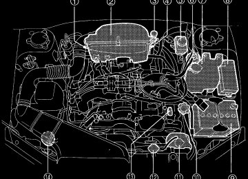
(cid:84) Components
10
12
11
UB1079DB
Seat, seatbelt and SRS airbags
1) Airbag control module (including
impact sensors)
2) Airbag module (driver’s side) 3) Airbag module (passenger’s
4) Front sub sensor (left hand side) 5) Front sub sensor (right hand
6) Seatbelt pretensioner (driver’s
7) Seatbelt pretensioner (passen-
ger’s side)
8) Side airbag module (driver’s
side – if equipped)
9) Side airbag module (passen-
ger’s side – if equipped)
10) Side airbag sensor (driver’s
side)
side)
side)
side)
side)
11) Side airbag sensor (passenger’s
12) Airbag wiring (yellow)
– CONTINUED – 1-61
Seat, seatbelt and SRS airbags
(cid:132) SRS frontal airbag The driver’s SRS frontal airbag is stowed in the center portion of the steering wheel. The passenger’s SRS frontal airbag is stowed near the top of the dashboard under an “SRS AIRBAG” mark. In a moderate to severe frontal collision, the driver’s and front passenger’s SRS frontal airbags deploy and supplement the seatbelts by reducing the impact on the driver’s and front passenger’s head and chest.
RISKS SERIOUS INJURY OR DEATH TO THE CHILD BY PLACING THE CHILD’S HEAD TOO CLOSE TO THE SRS AIRBAG.
HS1070BA
HG1043BA
Never allow a child to stand up, or to kneel on the front passenger’s seat. The SRS airbag de- ploys with considerable force and can injure or even kill the child.
NEVER INSTALL A REARWARD FACING CHILD SAFETY SEAT IN THE FRONT SEAT. DOING SO
1-62
Seat, seatbelt and SRS airbags
HS1069BA
HS1084BA
Never hold a child on your lap or in your arms. The SRS airbag deploys with considerable force and can injure or even kill the child.
The SRS airbag deploys with considerable speed and force. Occupants who are out of proper position when the SRS airbag deploys could suffer very serious injuries. Because the SRS airbag needs enough space for deploy- ment, the driver should always sit upright and well back in the seat as far from the steering wheel as practical while still maintaining full ve- hicle control and the front passenger should move the seat as far back as possible and sit upright and well back in the seat. It is also important to wear your seatbelt to help – CONTINUED – 1-63
Seat, seatbelt and SRS airbags
avoid injuries that can result when the SRS air- bag contacts an occupant not in proper posi- tion such as one thrown toward the front of the car during pre-accident braking.
UG1514BA
UG1513BA
Do not attach accessories to the windshield, or fit an extra-wide mirror over the rear view mir- ror. If the SRS airbag deploys, those objects could become projectiles that could seriously injure vehicle occupants.
Do not put any objects over the steering wheel pad and dashboard. If the SRS frontal airbag deploys, those objects could interfere with its proper operation and could be propelled inside the vehicle and cause injury.
1-64
(cid:84) Operation
Seat, seatbelt and SRS airbags
A) Driver’s side B) Passenger’s side 1) SRS airbags deploy as soon as a collision occurs. 2) After deployment, SRS airbags start to deflate immediately so that the driver’s vision is not obstructed.
HS1087BB
– CONTINUED – 1-65
Seat, seatbelt and SRS airbags
The SRS airbag can function only when the ignition switch is in the “ON” position. If the front sub sensors inside the both front fenders and the impact sensors in the airbag control module detect a certain predetermined amount of force during a frontal collision, the control module sends signals to the frontal airbag modules instructing them to inflate the SRS frontal airbags. Then both airbag modules produce gas, which instantly inflates driver’s and pas- senger’s SRS frontal airbags. After the deployment, the SRS airbags immediately start to deflate so that the driver’s vision is not obstructed. The time required from detecting impact to the deflation of the SRS air- bag after deployment is shorter than the blink of an eye. The front passenger’s SRS frontal airbag deploys to- gether with driver’s SRS frontal airbag even when no one occupies the front passenger’s seat. When the SRS frontal airbags deploy, the driver’s and front passenger’s seatbelt pretensioners operate at the same time. Although it is highly unlikely that the SRS airbag would activate in a non-accident situation, should it occur, the SRS airbag will deflate quickly, not obscuring vi- sion and will not interfere with the driver’s ability to
1-66
maintain control of the vehicle. When the SRS airbag deploys, a sudden, fairly loud inflation noise will be heard and some smoke will be released. These occurrences are normal result of the deployment. This smoke does not indicate a fire in the vehicle.
Do not touch the SRS airbag system compo- nents around the steering wheel and dash- board with bare hands right after deployment. Doing so can cause burns because the compo- nents can be very hot as a result of deployment.
The SRS frontal airbag is designed to deploy in the event of an accident involving a moderate to severe frontal collision. It is basically not designed to deploy in lesser frontal impacts because the necessary pro- tection can be achieved by the seatbelt alone. Also, it is basically not designed to deploy in side or rear im- pacts or in roll-over accidents because deployment of the SRS frontal airbag would not help the occupant in those situations. The SRS airbag is designed to func- tion on a one-time-only basis. SRS airbag deployment depends on the level of force
experienced in the passenger compartment during a collision. That level differs from one type of collision to another, and it may have no bearing on the visible damage done to the vehicle itself. (cid:86) Examples of accident in which the SRS frontal
airbag will most likely deploy.
Seat, seatbelt and SRS airbags
(cid:86) Examples of the types of accidents in which it is possible that the SRS frontal airbag will de- ploy.
UB1055BA
A head-on collision against a thick concrete wall at a vehicle speed of 12 to 19 mph (20 to 30 km/h) or high- er activates the SRS frontal airbag. The SRS frontal airbag will also be activated when the vehicle is ex- posed to a frontal impact similar in fashion and magni- tude to the above-mentioned collision.
UB1164BA
The SRS frontal airbag may be activated when the ve- hicle sustains a hard impact in the undercarriage area – CONTINUED – 1-67
Seat, seatbelt and SRS airbags
from the road surface (such as when the vehicle plunges into a deep ditch, is severely bumped or knocked hard against an obstacle on the road such as a curb).
(cid:86) Examples of the types of accidents in which the
SRS frontal airbag is unlikely to deploy.
There are many types of collisions which might not necessarily require SRS frontal airbag deployment. If the vehicle strikes an object, such as a telephone pole
UB1165BA
1-68
or sign pole, or if it slides under a truck’s load bed, or if it sustains an oblique offset frontal impact, the SRS frontal airbag may not deploy depending on the level of accident forces involved.
Seat, seatbelt and SRS airbags
(cid:86) Examples of the types of accidents in which the
SRS frontal airbag will basically not deploy.
UB1166BA
The SRS frontal airbag is basically not designed to de- ploy if the vehicle is struck from side or from behind, or if it rolls onto its side or roof, or if it is involved in a low- – CONTINUED – 1-69
(cid:132) SRS side airbag (if equipped) The SRS side airbag is stored in the door side of each front seatback, which bears an “SRS AIRBAG” label. In a moderate to severe side impact collision, the SRS side airbag on the impacted side of the vehicle de- ploys between the occupant and the door panel and supplements the seatbelt by reducing the impact on the occupant’s chest.
The SRS side airbag is designed as only a sup- plement to the primary protection provided by the seatbelt. It does not do away with the need to fasten seatbelts. It is also important to wear your seatbelt to help avoid injuries that can re- sult when an occupant is not seated in a proper upright position.
Seat, seatbelt and SRS airbags
speed frontal collision.
UB1070BB
1) First impact! 2) Second impact!! In an accident where the vehicle is impacted more than once, the SRS frontal airbag deploys only once. Example: In the case of a double collision, first with an- other vehicle, then against a concrete wall in immedi- ate succession, once the SRS frontal airbag is activat- ed on the first impact, it will not be activated on the second.
1-70
Seat, seatbelt and SRS airbags
HS1092BA
HS1093BA
Do not sit or lean unnecessarily close to either front door. The SRS side airbag is stored in both front seat seatbacks next to the door, and it provides protection by deploying rapidly (faster than the blink of an eye) in the event of a side impact collision. However, the force of SRS side airbag deployment may cause injuries if your head or other body parts are too close to the SRS side airbag.
Do not rest your arm on either front door or its internal trim. It could be injured in the event of SRS side airbag deployment.
– CONTINUED – 1-71
Never allow a child to kneel on the front pas- senger’s seat facing the side window or to wrap his/her arms around the front seat seatback. In the event of an accident, the force of SRS side airbag deployment could seriously injure or even kill the child because his/her head or arms or other body parts are close to the side airbag. Since your vehicle is also equipped with a pas- senger’s SRS frontal airbag, children aged 12
and under should be placed in the rear seat anyway and should be properly restrained at all times.Seat, seatbelt and SRS airbags
HS1094BA
HS1095BA
1-72
Seat, seatbelt and SRS airbags
HS1096BA
UG1534BA
Do not attach accessories to the door trim or near either SRS side airbags and do not place objects near the SRS side airbags. In the event of the SRS side airbag deployment, they could be propelled dangerously toward the vehicle’s occupants and cause injuries.
Do not put any kind of cover or clothes or other objects over either front seatback and do not attach labels or stickers to the front seat sur- face on or near the SRS side airbag. They could prevent proper deployment of the SRS side air- bag, reducing protection available to the front seat’s occupant.
– CONTINUED – 1-73
Seat, seatbelt and SRS airbags
(cid:84) Operation
UB0359
A) SRS side airbag deploys as soon as a collision oc-
B) After deployment, SRS side airbag starts to deflate im-
curs.
mediately.
1-74
The SRS side airbag can function only when the igni- tion switch is in the “ON” position. The driver’s and front passenger’s SRS side airbags deploy independently of each other since each has its own impact sensor. Also, the SRS side airbag deploys independently of the frontal airbags in the steering wheel and instrument panel. An impact sensor is incorporated into each of the ve- hicle’s center pillars. If either sensor detects a certain predetermined amount of force during a side impact collision, the control module sends a signal to the side airbag module on the impacted side of the vehicle, in- structing it to inflate the SRS side airbag. Then the side airbag module produces gas, which instantly in- flates the SRS side airbag. After the deployment, the SRS side airbag immediately starts to deflate. The time required from detecting impact to the deflation of the SRS side airbag after deployment is shorter than the blink of an eye. The SRS side airbag deploys even when no one occu- pies the seat on the side of which an impact is applied. When the SRS side airbag deploys, a sudden, fairly loud inflation noise will be heard and some smoke will be released. These occurrences are normal result of the deployment. This smoke does not indicate a fire in
the vehicle.
(cid:86) Example of the type of accident in which the
SRS side airbag will most likely deploy.
Seat, seatbelt and SRS airbags
Do not touch the SRS side airbag system com- ponents around the front seatback with bare hands right after deployment. Doing so can cause burns because the components can be very hot as a result of deployment.
The SRS side airbag is designed to deploy in the event of an accident involving a moderate to severe side im- pact collision. It is basically not designed to deploy in lesser side impact. Also, it is basically not designed to deploy in frontal or rear impacts because SRS side air- bag deployment would not help the occupant in those situations. Each SRS side airbag is designed to function on a one-time-only basis. SRS side airbag deployment depends on the level of force experienced in the passenger compartment dur- ing a side impact collision. That level differs from one type of collision to another, and it may have no bearing on the visible damage done to the vehicle itself.
A severe side impact near the front seat activates the SRS side airbag.
UB0313
– CONTINUED – 1-75
1) The vehicle is involved in an ob-
lique side impact.
2) The vehicle is involved in a side
impact in an area outside the vicin- ity of the passenger compartment.
3) The vehicle strikes a telephone
pole or similar object.
4) The vehicle is involved in a side
impact from a motorcycle.
5) The vehicle rolls onto its side or
roof.
Seat, seatbelt and SRS airbags
(cid:86) Examples of the types of accidents in which the SRS side airbag
is unlikely to deploy.
UB1167BB
1-76
There are many types of collisions which might not necessarily require SRS side airbag deployment. In the event of accidents like those illustrated below, the SRS side airbag may not deploy depending on the lev- el of accident forces involved.
Seat, seatbelt and SRS airbags
(cid:86) Examples of the types of accidents in which the
SRS side airbag will basically not deploy.
1) The vehicle is involved in a frontal collision with anoth-
er vehicle (moving or stationary). 2) The vehicle is struck from behind.
UB1168BB
– CONTINUED – 1-77
Seat, seatbelt and SRS airbags
The SRS side airbag is basically not designed to de- ploy if the vehicle is involved in a frontal collision or is struck from behind. Examples of such accidents are il- lustrated below.
vated on the second.
(cid:132) SRS airbag system monitors
UB1071BB
1) First impact! 2) Second impact!! In an accident where the vehicle is struck from the side more than once, the SRS side airbag deploys only once. Example: In the case of a double side impact collision, first with one vehicle and immediately followed by an- other from the same direction, once the SRS side air- bag is activated on the first impact, it will not be acti-
1-78
UB4010EA
SRS airbag system warning light A diagnostic system continually monitors the readi- ness of the SRS airbag system (including front seat- belt pretensioners) while the vehicle is being driven. The SRS airbag system warning light “AIRBAG” will show normal system operation by lighting for about 6
seconds when the ignition key is turned to the “ON” position. The following components are monitored by the indi-cator: (cid:121) Front sub sensor (Right hand side) (cid:121) Front sub sensor (Left hand side) (cid:121) Airbag control module (including impact sensors) (cid:121) Frontal airbag module (Driver’s side) (cid:121) Frontal airbag module (Passenger’s side) (cid:121) Side airbag sensor (Driver’s side – if equipped) (cid:121) Side airbag sensor (Passenger’s side – if equipped) (cid:121) Side airbag module (Driver’s side – if equipped) (cid:121) Side airbag module (Passenger’s side – equipped) (cid:121) Seatbelt pretensioner (Driver’s side) (cid:121) Seatbelt pretensioner (Passenger’s side) (cid:121) All related wiring In the event of a malfunction indicated by any of follow- ing, the vehicle should be taken promptly to your near- est SUBARU dealer to have the system checked. Un- less checked and repaired, the SRS airbags will not function reliably: (cid:121) Flashing or flickering of the indicator light. (cid:121) No illumination of the warning light when the ignition switch is first turned to the “ON” position. (cid:121) Continuous illumination of the warning light. (cid:121) Illumination of the warning light while driving.
if
Seat, seatbelt and SRS airbags
(cid:132) SRS airbag system servicing
(cid:121) When discarding an airbag module or scrap- ping the entire car damaged by a collision, con- sult your SUBARU dealer. (cid:121) The SRS airbag has no user-serviceable parts. Do not use electrical test equipment on any circuit related to the SRS airbag system. For required servicing of the SRS airbag, see your nearest SUBARU dealer. Tampering with or disconnecting the system’s wiring could re- sult in accidental inflation of the SRS airbag or could make the system inoperative, which may result in serious injury. The wiring harnesses of the SRS airbag system are covered with yellow insulation and system connectors are yellow for easy identification.
If you need service or repair in areas listed be- low, we recommend that you have an autho- rized SUBARU dealer perform the work. The SRS airbag control module, impact sensors and airbag modules are stored in these areas.
– CONTINUED – 1-79
Seat, seatbelt and SRS airbags
(cid:121) Under the center console (cid:121) Inside each front fender (cid:121) Steering wheel and column and nearby areas (cid:121) Top of the dashboard on front passenger’s side and nearby areas (cid:121) Each front seat and nearby area (only for ve- hicles with SRS side airbags) (cid:121) Inside each center pillar
In the event that the SRS airbag is deployed, re- placement of the system should be performed only by an authorized SUBARU dealer. When the components of the SRS airbag system are re- placed, use only genuine SUBARU parts. To ensure their long-term reliability, the SRS airbags must be inspected by a SUBARU dealer ten years af- ter the date of manufacture, which is shown on the cer- tification label attached to the driver’s door. NOTE In the following cases, contact your SUBARU deal- er as soon as possible. (cid:121) The front part of the vehicle was involved in an accident in which the SRS frontal airbags did not deploy. (cid:121) The pad section of the steering wheel or front
1-80
passenger’s frontal airbag cover is scratched, cracked, or otherwise damaged. In addition, if your vehicle is equipped with SRS side airbags, contact your SUBARU dealer as soon as possible in the following cases. (cid:121) Either center pillar or a nearby area of the vehi- cle was involved in an accident in which the SRS side airbag did not deploy. (cid:121) The fabric or leather of either front seatback is cut, frayed, or otherwise damaged.
(cid:132) Precautions against vehicle modifica-
tion
(cid:121) To avoid accidental activation of the system or rendering the system inoperative, which may result injury, no modifications should be made to any components or wiring of the SRS airbag system. This includes following modifications:
in serious
(cid:121) Installation of custom steering wheels (cid:121) Attachment of additional trim materials to the dashboard (cid:121) Installation of custom seats (only for vehi-
cles with SRS side airbags) (cid:121) Replacement of seat fabric or leather (only for vehicles with SRS side airbags) (cid:121) Installation of additional fabric or leather on the front seat (only for vehicles with SRS side airbags)
(cid:121) Installation of additional electrical/electronic equipment such as a mobile two-way radio on or near the SRS airbag system components and/or wiring is not advisable. This could inter- fere with proper operation of the SRS airbag system.
Do not perform any of the following modifica- tions. Such modifications can interfere with proper operation of the SRS airbag system. (cid:121) Attachment of any equipment (brush bar, winches, snow plow, skid plate, etc.) other than SUBARU genuine accessory parts to the front end. (cid:121) Modification of the suspension system or front end structure. (cid:121) Installation of a tire of different size and con- struction from the tires specified on the tire
Seat, seatbelt and SRS airbags
placard attached to the driver’s door jamb. (cid:121) Attachment of any equipment (side steps or side sill protectors, etc.) other than SUBARU genuine accessory parts to the side body (only for vehicles with side airbags).
Always consult your SUBARU dealer if you want to in- stall any accessory parts to your vehicle.
– CONTINUED – 1-81
Keys ............................................................... Key number ....................................................... Door locks ..................................................... Locking and unlocking from the outside ........ Locking and unlocking from the inside .......... Power door locking switches ...................... Remote keyless entry system (if equipped) .............................................. Locking the doors ............................................. Unlocking the doors ......................................... Illuminated entry ............................................... Vehicle finder function ..................................... Sounding a panic alarm ................................... Selecting audible signal operation .................. Replacing the battery ....................................... Replacing lost transmitters .............................. Security system (if equipped) ..................... System operation .............................................. Arming the system ............................................ Disarming the system ....................................... Sounding a panic alarm ................................... Valet mode ......................................................... Passive arming .................................................. Child safety locks ......................................... Windows ........................................................ Power windows ................................................. Trunk lid (Sedan) .......................................... To open and close the trunk lid from outside ............................................................ To open the trunk lid from inside ....................
2-2
2-2
2-3
2-3
2-4
2-5
2-7
2-8
2-8
2-9
2-9
2-9
2-9
2-10
2-11
2-15
2-15
2-15
2-17
2-18
2-18
2-18
2-22
2-23
2-23
2-26
2-27
2-27Keys and doors
To cancel the trunk lid release ........................ Internal trunk lid release handle ......................
2-28
2-28
Rear gate (Station wagon) ............................ 2-31
Moonroof (if equipped) ................................. 2-32
2-33
2-34Tilting/sliding moonroof (Sedan) .................... Dual moonroofs (Station wagon) ....................
2-1
Keys and doors
Keys and doorsKeys
HS2011BB
1) Master key 2) Submaster key 3) Valet key 4) Key number plate Three types of keys are provided for your vehicle. Master key, submaster key and valet key. The master key and submaster key fit all locks on your vehicle. (cid:121) Ignition switch (cid:121) Doors (cid:121) Trunk (sedan) or Rear gate (station wagon)
2-2
(cid:121) Glove box The valet key fits only the ignition switch and door locks. You can keep the trunk and glove box locked when you leave your vehicle and valet key at a parking facility. NOTE If the key is attached to a keyholder or to a large bunch of other keys, centrifugal force may act on it as the vehicle moves, resulting in unwanted turning of the ignition switch. Also, if a large key- holder is attached to the key, your knees or hands may accidentally touch it in a way that turns the ig- nition switch.
(cid:132) Key number The key number is stamped on the metal plate at- tached to the key set. Write down the key number and keep it in another safe place, not in the vehicle. This number is needed to make a replacement key if you lose your key or lock it inside the vehicle.
Door locks (cid:132) Locking and unlocking from the out-
side
OM-U2394
To lock the door from the outside with the key, turn the key toward the rear. To unlock the door, turn the key toward the front. Lift the outside door handle to open an unlocked door.
Keys and doors
UB2024BD
Locking without the key 1) Rotate the lock lever rearward. 2) Close the door. To lock the door from the outside without the key, ro- tate the lock lever rearward and then close the door.
– CONTINUED – 2-3
Keys and doors
vehicle before locking the doors from the outside without the key.
(cid:132) Locking and unlocking from the inside
Keep all doors locked when you drive, especial- ly when small children are in your vehicle. Along with the proper use of seat belts and child restraints, locking the doors reduces the chance of being thrown out of the vehicle in an accident. It also helps prevent passengers from falling out if a door is accidentally opened, and intrud- ers from unexpectedly opening doors and en- tering your vehicle.
UB2024CB
Locking without the key 1) Push the power door locking switch forward. 2) Close the door. To lock the door from the outside using the power door locking switch, push the switch forward (“LOCK” side) and then close the door. In this case, all closed doors and the rear gate (for station wagon) are locked at the same time. Always make sure that all doors and the rear gate are locked before leaving your vehicle. NOTE Make sure that you do not leave the key inside the
2-4
1
UB2001BC
1) Lock 2) Unlock To lock the door from the inside, rotate the lock lever rearward. To unlock the door from the inside, rotate the lock lever forward. The red mark on the lock lever appears when the door is unlocked. Pull the inside door handle to open an unlocked door. Always make sure that all doors and the rear gate (sta- tion wagon) are closed and locked before starting to drive.
Keys and doors
Power door locking switches
Driver’s switch 1) Lock 2) Unlock
UB2008CB
– CONTINUED – 2-5
NOTE Make sure that you do not leave the key inside the vehicle before locking the doors from the outside using power door locking switches.
Keys and doors
UB2009BB
Front passenger’s switch 1) Lock 2) Unlock All doors and the rear gate (station wagon) can be locked and unlocked by the power door locking switch- es located at the driver’s side and the front passen- ger’s side doors. To lock the doors, push the switch forward. To unlock the doors, push the switch rearward. When you close the doors after you set the door locks, the doors remain locked.
2-6
Remote keyless entry system (if equipped)
(cid:121) Do not expose the transmitter to severe shocks, such as those experienced as a result of dropping or throwing. (cid:121) Do not take the transmitter apart except when replacing the battery. (cid:121) Do not get the transmitter wet. If it gets wet, wipe it dry with a cloth immediately.
This device complies with Part 15 of the FCC Rules and with RSS-210 of Industry Canada. Oper- ation is subject to the following two conditions: (1) This device may not cause harmful interference, and (2) this device must accept any interference received, including interference that may cause undesired operation. Changes or modifications not expressly approved by the party responsible for compliance could void the user’s authority to operate the equipment. Two transmitters are provided for your vehicle. The keyless entry system has the following functions.
Keys and doors
(cid:121) Locking and unlocking the doors (and rear gate on the station wagon) without a key (cid:121) Sounding a panic alarm (cid:121) Arming and disarming the security system (if your vehicle is equipped with an optional security system). See the next section “Security system (if equipped)” for detailed information. The operable distance of the keyless entry system is approximately 30 feet (10 meters). However, this dis- tance will vary depending on environmental condi- tions. Range may be reduced near sources of RF in- terference such as power plants and radio/television broadcasting towers. The keyless entry system does not operate when the key is inserted in the ignition switch.
– CONTINUED – 2-7
Keys and doors
B1
B2
HS2016BB
A: “LOCK/ARM” button (Orange)
Press to lock all doors. Press and Hold to activate panic alarm. Press three times in a five second period to use vehi- cle finder function.
B: “UNLOCK/DISARM” button (Blue)
1) Press once to Unlock driver’s door. 2) Press a second time to Unlock all other doors and
rear gate.
C: LED
(cid:132) Locking the doors Briefly press the “LOCK/ARM” button (for less than two seconds) to lock all doors (and rear gate on the
2-8
station wagon). An electronic chirp will sound one time and the turn signal lights will flash one time. If any of the doors (or the rear gate) is not fully closed, an electronic chirp will sound five times and the turn signal lights will flash five times to alert you that the doors (or the rear gate) are not properly closed. When you close the door, it will automatically lock. NOTE If the “LOCK/ALARM” button is pressed for two seconds or longer, the panic alarm will sound. When locking the doors in normal circumstances, press the “LOCK/ALARM” button for less than two seconds. For details on the panic alarm, refer to “Sounding a panic alarm”.
(cid:132) Unlocking the doors Briefly press the “UNLOCK/DISARM” button (for less than two seconds) to unlock the driver’s door. An elec- tronic chirp will sound two times and the turn signal lights will flash two times. To unlock all doors (and rear gate on the station wagon), briefly press the “UN- LOCK/DISARM” button a second time within 5 sec- onds. NOTE If the interval between the first and second press-
es of the “UNLOCK/DISARM” button (for unlock- ing of all of the doors and the rear gate) is extreme- ly short, the system may not respond.
(cid:132) Illuminated entry The interior (dome) light will illuminate when the “UN- LOCK/DISARM” button is pressed. These lights stay illuminated for approximately 30 seconds if any of the doors (or the rear gate on the station wagon) is not opened. If the “LOCK/ARM” button is pressed before 30 sec- onds have elapsed, these lights will go out. Also, these lights will go out if the key is inserted in the ignition switch. The interior light must be set to the middle po- sition in order for this function to operate.
(cid:132) Vehicle finder function Use this function to find your vehicle parked among many vehicles in a large parking lot. Provided you are within 30 feet (10 meters) of the vehicle, pressing the “LOCK/ARM” button three times in a five-second peri- od will cause your vehicle’s horn to sound one time and its turn signal lights to flash three times.
(cid:132) Sounding a panic alarm To activate the alarm, keep the “LOCK/ARM” button
Keys and doors
pressed for more than two seconds. The horn will sound and the turn signal lights will flash. To deactivate it, press the “LOCK/ARM” button or “UNLOCK/DISARM” button. Unless a button on the re- mote is pressed, the alarm will be deactivated after ap- proximately 30 seconds.
(cid:132) Selecting audible signal operation Using an electronic chirp, the system will give you an audible signal when the doors lock and unlock. If de- sired, you may turn the audible signal off. To turn the audible signal off, unlock the doors by pushing “UNLOCK/DISARM” button and then simulta- neously depress “LOCK/ARM” and “UNLOCK/DIS- ARM” buttons for more than two seconds. An electron- ic chirp will sound two times and the turn signal lights will flash two times to inform you that the audible signal has been turned off. To turn the audible signal on, unlock the doors by pushing “UNLOCK/DISARM” button and then simulta- neously depress “LOCK/ARM” and “UNLOCK/DIS- ARM” buttons for more than two seconds. An electron- ic chirp will sound one time and the turn signal lights will flash one time to inform you that the audible signal has been turned on.
– CONTINUED – 2-9
Keys and doors
(cid:132) Replacing the battery
Do not let dust, oil or water get on or in the transmitter when replacing the battery.
When the transmitter battery begins to get weak, transmitter range will begin to decrease and the LED will not illuminate. Replace the battery as soon as pos- sible. To replace the battery:
1. Remove the two screws on the back of the trans-
HS2017BA
2-10
mitter case by using a phillips screwdriver. 2. Separate the case. 3. Remove the old battery from the holder.
HS2018BB
1) Positive (+) side facing up 4. Replace with a new battery (Type CR2032 or equivalent) making sure to install the new battery with the positive (+) side facing up. 5. Install the back half of the transmitter case. 6. Reinstall the two screws on the back of the trans- mitter case. After the battery is replaced, the transmitter must be synchronized with the keyless entry system’s control unit. Press either the “LOCK/ARM” or “UN-
LOCK/DISARM” button six times to synchronize the unit.
(cid:132) Replacing lost transmitters If you lose a transmitter or want to purchase additional transmitters (up to four can be programmed), you should re-program all of your transmitters for security reasons. It is recommended that you have your dealer program all of your transmitters into your system. (cid:84) Programming the transmitters The keyless entry system is equipped with a special code learning feature that allows you to program new transmitter codes into the system or to delete old ones. The system can learn up to four unique transmit- ter codes. The four transmitter codes may be the same or different.
Keys and doors
To enter the programming mode:
1. Press “UNLOCK/DISARM” button to disarm the se- curity system. (if your vehicle is equipped with the op- tional security system.)
HS2016CA
– CONTINUED – 2-11
Keys and doors
HS2019BB
HS2020BB
2. Open the driver’s door and sit in the driver’s seat. 3. Close the driver’s door.
1) ON 2) LOCK 4. Place the ignition key into the ignition switch and cycle the switch from LOCK to ON ten times within 15
seconds. Be sure to stop at the LOCK position. The horn will sound once to indicate that you are in the transmitter programming mode. NOTE You must finish the next step (opening the driver’s door) within 45 seconds of starting this proce- dures.2-12
To program the transmitters:
1. Open the driver’s door. 2. Close the driver’s door.
HS2019BC
Keys and doors
HS2016DB
1) Press any button. 3. Press and release any button on the transmitter that you wish to program into the system. The horn will sound two times to indicate that the transmitter has been programmed. Any additional transmitters can also be programmed at this time. Repeat steps 1 through 3 for an additional transmitter. To exit the programming mode: 1. After all of your transmitters are programmed, re- move the key from the ignition switch. The horn will sound three times to indicate that the – CONTINUED – 2-13
to your vehicle.
Keys and doors
system has exited the programming mode. 2. Make sure that the keyless entry system properly operates by operating each transmitter. (cid:84) Deleting old transmitter codes The control unit of the keyless entry system has four memory locations to store transmitter codes, giving it the ability to operate with up to four transmitters. When you lose a transmitter, the lost transmitter’s code re- mains in the memory. For security reasons, lost trans- mitter codes should be deleted from the memory. To delete old transmitter codes, program four trans- mitter codes into the system. If you have only one cur- rent transmitter, program it four times. If you have two current transmitters, program each one twice. If you have three current transmitters, program two of them once and the third one twice. This process will leave only current transmitter codes in the system’s memo- ry. NOTE Make sure no one else is operating their keyless entry system within range of your vehicle when programming transmitters. If someone else were to operate their remote transmitter while you are programming your transmitters, it is possible that their transmitter code will be programmed into your system, allowing them unauthorized access
2-14
Security system (if equipped) The security system helps to protect your vehicle and valuables from theft. The horn sounds and the turn signal lights flash if someone attempts to break into your vehicle. The starter motor is also interrupted to prevent starting the vehicle without a key. The system can be armed and disarmed with the re- mote transmitter. The system does not operate when the key is inserted into the ignition switch.
(cid:132) System operation The security system will give the following alarm indi- cations when triggered: (cid:121) The turn signal lights will flash and the horn will sound intermittently. In addition, the starter motor will not operate. (cid:121) The alarm automatically resets after 30 seconds; however, the alarm will reactivate if the vehicle is tam- pered with again. The alarm will continue for six times if any sensor continues to be activated. The alarm is triggered by: (cid:121) Opening a door, the rear gate or trunk lid. (cid:121) Application of physical shock to the vehicle (e.g.
Keys and doors
breaking glass or forced entry). Note that there are two alarm levels for shock: warning and alarm. In warning mode, the alarm detects lower level vibrations and triggers 2 warning chirps on the horn and two flashes on the lights as a deterrent to would be vandals. In alarm mode, higher levels of shock are detected and the system will go into full alarm. (cid:121) Ignition switch being turned on while in armed state. NOTE With the valet mode selected, the security system does not operate and the parking lights do not flash when the remote transmitter is used for lock- ing and unlocking. The security system indicator light in the combi- nation meter flashes twice per second to show that the valet mode is selected. For details, refer to “Valet mode” in this section.
(cid:132) Arming the system (cid:84) To arm the system using remote transmitter 1. Close all windows and moonroofs (if so equipped). 2. Remove the key from the ignition switch. 3. Open the doors and get out of the vehicle. 4. Make sure that the engine hood (and the trunk lid) are locked.
– CONTINUED – 2-15
Keys and doors
5. Close all doors (and the rear gate on the station wagon).
1) Press to Arm the system. 2) Press to Disarm the system.
HS2016EB
2-16
UB2033BB
1) Security system indicator light 6. Briefly press the “LOCK/ARM” button (for less than two seconds). All doors (and the rear gate on the sta- tion wagon) will lock, an electronic chirp will sound one time, the turn signal lights will flash one time and the indicator light starts flashing slowly (approximately once every two seconds). If any of the doors, (rear gate or trunk lid) is not fully closed, an electronic chirp sounds five times, the turn signal lights flash five times to alert you that the doors (or the rear gate) are not properly closed. When you close the door, the system will automatically arm and doors will automatically lock.
(cid:84) To arm the system using power door locking
switches
1. Close all windows and moonroofs (if so equipped). 2. Remove the key from the ignition switch. 3. Open the doors and get out of the vehicle. 4. Make sure that the engine hood (and the trunk lid) is locked. 5. Close the doors (and the rear gate on the station wagon) but leave only the driver’s door or the front passenger’s door open.
UB2024CC
6. Push the power door locking switch forward (“LOCK” side) to set the door locks. 7. Close the door. An electronic chirp will sound one time, the turn signal lights will flash one time and the
Keys and doors
indicator light will start flashing slowly (approximately once every two seconds) to inform you that the system has armed. NOTE The system can be armed even if the engine hood, the windows and/or moonroofs are opened. Al- ways make sure that they are fully closed before arming the system.
(cid:132) Disarming the system Briefly press the “UNLOCK/DISARM” button (for less than two seconds) on the remote transmitter. The driv- er’s door will unlock, an electronic chirp will sound two times, the turn signal lights will flash two times and the indicator light will go off. To unlock all other doors (and the rear gate on the sta- tion wagon), briefly press the “UNLOCK/DISARM” but- ton a second time. (cid:84) Emergency disarming If you cannot disarm the system using the transmitter (i.e. the transmitter is lost, broken or the transmitter battery is too weak), you can disarm the system with- out using the transmitter. To disarm the system:
– CONTINUED – 2-17
Keys and doors
1. Unlock the door with the key and then open the door. 2. The alarm will sound. 3. Insert the key into the ignition switch and cycle it from the “LOCK” to the “ON” position three (3) times within 5 seconds.
(cid:132) Sounding a panic alarm To activate the alarm, keep the “LOCK/ARM” button pressed for more than two seconds. The horn will sound and the turn signal lights will flash. To deactivate it, press the “LOCK/ARM” button or “UNLOCK/DISARM” button. Unless a button on the remote is pressed, the alarm will be deactivated after approximately 30 seconds.
(cid:132) Valet mode When you choose the valet mode, the security system does not operate. In valet mode, the remote transmit- ter is used only for locking and unlocking the doors (and rear gate on the station wagon) and panic activa- tion. To enter the valet mode, open the driver’s door and keep the “UNLOCK/DISARM” button depressed for more than two seconds. The security system indica- tor light will continue to flash 2 times per second indi-
2-18
cating that the system is in the valet mode. To exit valet mode, open the driver’s door and keep the “UNLOCK/DISARM” button pressed for more than two seconds. The indicator will stop flashing.
(cid:132) Passive arming When passive arming mode has been programmed by the dealer, arming of the system is automatically ac- complished without using the remote transmitter. Note that in this mode, DOORS MUST BE MANUALLY LOCKED. (cid:84) To enter the passive mode
Do not disconnect or tamper with any yellow connector and/or any harness covered with yel- low insulation and/or tape. Doing so could result in accidental inflation of the SRS airbag or could make the SRS airbag system inoperative, which may result in serious injury.
0
Keys and doors
UB2036BA
HS2023BB
1. Remove the side sill cover on the driver’s side.
1)Open the driver’s door. 2)Remove the two clips fastening the front portion of the cover with a screwdriver. 3)Remove the side sill cover by pulling it up.
1) Connector for SRS airbag system (yellow) 2) White (1P) 2. Connect the white (1 pole) connector. 3. Turn the ignition switch from the “LOCK” to the “ON” position. 4. Install the side sill cover. To place the system in active arming mode (remote re- quired for activation), disconnect the white connector.
– CONTINUED – 2-19
Keys and doors
(cid:84) Arming the system
In passive mode, the system will automatically activate the alarm but WILL NOT automatically lock the doors. In order to lock the doors you must either lock them as indicated in step 4 be- low or with the key once they have been closed. Failure to lock the doors manually will result in a higher security risk.
1. Turn the ignition switch to the “ON” position.
HS2024BB
1) ON 2) LOCK 2. Turn the ignition switch from “ON” to “LOCK” posi- tion and remove the key from the ignition switch.
2-20
4
UB2024DB
3. Open the doors and get out of the vehicle. 4. Before closing the doors, lock all doors with the in- side door lock levers. 5. Close the doors. The system will automatically arm after one minute. In the passive mode, the system can also be armed with the remote transmitter or with the power door locking switches. If the remote transmitter or power door lock switch is used to lock the vehicle, arming will take place immediately regardless of whether or not the passive mode has been selected. (cid:84) Disarming the system To disarm the system, briefly press the “UNLOCK/
Keys and doors
DISARM” button on the transmitter. (cid:84) Tripped sensor identification If an electronic chirp sounds four times and the turn signal lights flash four times when you disarm the sys- tem, this indicates that the alarm was triggered. The number of times the indicator light flashes indicates what sensor caused the alarm condition. To enter identification mode: 1. Open the driver’s door and leave it open. 2. Turn the ignition switch to the “ON” position two times. (“LOCK” → “ON” → “LOCK” → “ON” → “LOCK”) 3. The indicator light will start flashing. The indicator light provides the following indications. Flashing one time: Any door, the rear gate or the trunk lid has been opened. Flashing three times: The impact sensor in the sys- tem’s unit has been activated. This may indicate that your vehicle has been shocked or tampered with by some outside force and/or unauthorized person. Flashing four times: The ignition switch has been turned on or the battery has been disconnected. NOTE The battery must be reconnected before the indi- cator light will flash.
– CONTINUED – 2-21
Keys and doors
To exit this mode, close the door and turn the ignition switch to the “ON” position.
Child safety locks
Always use the child safety lock whenever a child rides in the rear seat. Serious injury could result if a child accidentally opened the door and fell out.
1) Lock 2) Unlock Each rear door has a child safety lock that prevents
UB2002BB
2-22
the doors from being opened even if the inside door handle is pulled. When the child safety lock lever is in the lock position, the door cannot be opened from inside regardless of the position of the inner door handle lock lever. The door can only be opened from the outside.
Keys and doors
Windows (cid:132) Power windows
To avoid serious personal injury caused by en- trapment, you must do the followings. (cid:121) When operating the power windows, be ex- tremely careful to prevent anyone’s fingers, arms, neck or head from being caught in the window. (cid:121) Always lock the passengers’ windows using the lock switch when children are riding in the vehicle. (cid:121) Before leaving the vehicle, always remove the key from the ignition switch for safety and never allow an unattended child to remain in the vehicle. Failure to follow this procedure could result in injury to a child operating the power window.
The power windows operate only when the ignition switch is in the “ON” position.
– CONTINUED – 2-23
Keys and doors
(cid:84) Driver’s side switches
(cid:86) Operating the driver’s window
UB2008BB
UB2008DB
1) Lock switch 2) For driver’s window 3) For rear left passenger’s window 4) For front passenger’s window 5) For rear right passenger’s window All door windows can be controlled by the power win- dow switch cluster at the driver side door.
1) Lock 2) Unlock 3) Close 4) Open 5) Automatically open To open: Push the switch down lightly and hold it. The window will open as long as the switch is held. This switch also has a one-touch auto down feature that allows the window to be opened fully without hold- ing the switch. Push the switch down until it clicks and release it, and the window will fully open. To stop the window half-
2-24
way, pull the switch up lightly. To close: Pull the switch up lightly and hold it. The window will close as long as the switch is held. (cid:86) Operating the passengers’ windows To open the passengers’ windows, push the appropri- ate switch down and hold it until the window reaches the desired position. To close the window, pull the switch up and hold it until it reaches the desired posi- tion. (cid:86) Locking the passengers’ windows To lock the passengers’ windows, push the lock switch. When the lock switch is in the “LOCK” position, the passengers’ windows cannot be opened or closed.
Keys and doors
(cid:84) Passengers’ side switches
1) Open 2) Close
UB2009CB
– CONTINUED – 2-25
Trunk lid (Sedan)
(cid:121) To prevent dangerous exhaust gas from en- tering the vehicle, always keep the trunk lid closed while driving. (cid:121) Help prevent young children from locking themselves in the trunk. When leaving the vehi- cle, either close all windows and lock all doors or cancel the inside trunk lid release. Also make certain that the trunk is closed. On hot or sunny days, the temperature in the trunk could quickly become high enough to cause death or serious heat-related injuries including brain damage, particularly for small children.
Keys and doors
UB2005BB
1) Open 2) Close To open the window, push the switch down and hold it until the window reaches the desired position. To close the window, pull the switch up and hold it until the window reaches the desired position. When the lock switch on the power window switch cluster, located on the driver’s side door, is in the “LOCK” position, the passengers’ windows cannot be operated with the passengers’ switches.
2-26
(cid:132) To open and close the trunk lid from
outside
(cid:132) To open the trunk lid from inside
Keys and doors
UBF013CB
1) Open To open the trunk lid from outside, insert the key and turn it clockwise. To close the trunk lid, lightly press the trunk lid down until the latch engages.
1) Open Pull the trunk lid release lever upward.
UB3000CB
– CONTINUED – 2-27
Keys and doors
(cid:132) To cancel the trunk lid release
trunk, the handle allows them to open the lid. The han- dle is located on the inside of the trunk lid.
UBF014BA
The inside trunk lid release can be cancelled to help prevent unauthorized entry into the trunk. To cancel the trunk lid release, set the lid release cancel lever (located on the inside of the trunk lid, mounted to the trunk lid latch) to the “CANCEL” position. When this lock is in the “CANCEL” position, the trunk can be opened only with the key.
(cid:132) Internal trunk lid release handle The internal trunk lid release handle is a device de- signed to open the trunk lid from inside the trunk. In the event children or adults become locked inside the
UBS070BA
To open the trunk lid from inside the trunk, press the yellow handle downward as indicated by the arrow on the handle. This operation unlocks the trunk lid. Then, push up the lid. The handle is made of material that remains lumines- cent for approximately an hour in the dark trunk space after it is exposed to ambient light even for a short time.
Never allow any child to get in the trunk and
2-28
play with the release handle. If the driver starts the vehicle without knowing that a child is in- side the trunk and the child opens the lid using the release handle, the child could fall out and be killed or seriously injured.
1. Open the trunk lid.
Keys and doors
(cid:121) Do not close the lid while gripping the release handle. The handle may be damaged. (cid:121) Do not use the handle as a hook to fasten straps or ropes to secure your cargo in the trunk. Such use may result in damage of the handle. (cid:121) Load the trunk so that cargo can not strike the release handle. If the cargo hits the handle while the vehicle is being driven, the handle may be pushed down and the trunk lid may open. That may cause cargo to fall out of the trunk, which could create a traffic safety haz- ard.
(cid:84) Inspection Perform the following steps at least twice a year to check the release handle for correct operation.
2. Use a screwdriver with a thin blade. Slide the screwdriver blade from the slit aperture of the lock as- sembly fully to the end until you hear a click.
UBS071BA
– CONTINUED – 2-29
3. Move the release handle, from outside the vehicle, in the direction of the arrow to check if the latch is re- leased. If the latch is not released, contact your SUBARU dealer. In that case, use the key to release the latch, then close the trunk lid. Also, if the movements of the release handle feel re- stricted or not entirely smooth during operation, or the handle and/or handle base is cracked, contact your SUBARU dealer.
Keys and doors
This places the latch in the locked position.
UBS072BA
UG2018BA
2-30
Rear gate (Station wagon)
Then, hold the rear gate and raise it as high as it will go.
Keys and doors
UB2022BB
1) Lock 2) Unlock To unlock the rear gate, insert the key in the keyhole and turn it clockwise. To lock the rear gate, insert the key in the keyhole and turn it counterclockwise. If your vehicle is equipped with power door locking switches, the rear gate can also be locked and unlocked through use of the power door locking switches. Refer to “Pow- er door locking switches” section in this chapter. To open the rear gate, first unlock the rear gate lock then pull the outside handle up.
UG2512BA
To close the rear gate, lower it slowly and push down firmly until the latch engages. The rear gate can be lowered easily if you pull down on the recessed grip.
(cid:121) To prevent dangerous exhaust gas from en- tering the vehicle, always keep the rear gate closed while driving. (cid:121) Do not attempt to shut the rear gate while holding the recessed grip. Also avoid closing – CONTINUED –