- 2006 Subaru Legacy Owners Manuals
- Subaru Legacy Owners Manuals
- 2004 Subaru Legacy Owners Manuals
- Subaru Legacy Owners Manuals
- 2008 Subaru Legacy Owners Manuals
- Subaru Legacy Owners Manuals
- 2005 Subaru Legacy Owners Manuals
- Subaru Legacy Owners Manuals
- 2007 Subaru Legacy Owners Manuals
- Subaru Legacy Owners Manuals
- 2000 Subaru Legacy Owners Manuals
- Subaru Legacy Owners Manuals
- 2003 Subaru Legacy Owners Manuals
- Subaru Legacy Owners Manuals
- 2012 Subaru Legacy Owners Manuals
- Subaru Legacy Owners Manuals
- 2001 Subaru Legacy Owners Manuals
- Subaru Legacy Owners Manuals
- 2010 Subaru Legacy Owners Manuals
- Subaru Legacy Owners Manuals
- 2011 Subaru Legacy Owners Manuals
- Subaru Legacy Owners Manuals
- 2009 Subaru Legacy Owners Manuals
- Subaru Legacy Owners Manuals
- 2002 Subaru Legacy Owners Manuals
- Subaru Legacy Owners Manuals
- Download PDF Manual
-
11-30
11-32
11-33
11-34
11-35
11-36
11-37
11-38
11-39
11-39
11-40
11-41
11-42
11-43
11-45
11-46
11-48
11-48
11-4911
Legacy U.S.A..(ENG.)A2280BE–A
Headlight Front fog light (if equipped) Front turn signal light, parking light and marker light Rear combination lights License plate light Dome light, spot light, luggage compartment light
. . . . . . . . . . . . . . . . . . . . . . . . . . . . . . . . . . . . . . . . . . . . . . . . . . . . . . . . . . . . . . . . . . . . . . . . . . . . . . . . . . . . . . . . . . . . . . . . . . . . . . . . . . . . . . . . . . . . . . . . . . . . . . . . . . . . . . . . . . . . . . . . . . . . . . . . . . . . . . . . . . . . . . . . . . . . . . . . . . . . . . . . . . . . . . . . . . . . . . . . . . . . . . . . . . . . . . . . . . . . . . . .
and door step light
Trunk light High mount stop light
. . . . . . . . . . . . . . . . . . . . . . . . . . . . . . . . . . . . . . . . . . . . . . . . . . . . . . . . . . . . . . . . . . . . . . . . . . . . . . . . . . . . . . . . . . . . . . . . . . . . . . . . . . . . . . . . . . . . . . . . . . . . . . . . . . . . . . . . . . . . . . . . . . . . . . . . . . . . . . . . . . . . . . .
11-51
11-53
11-53
11-55
11-5811-59
11-60
11-6011-2
Legacy U.S.A..(ENG.)A2280BE–A
Maintenance and service
Maintenance schedule
The scheduled maintenance items required to be serviced at regular in- tervals are shown in the “Warranty and Maintenance Booklet”.
For details of your maintenance schedule, read the separate “Warranty and Maintenance Booklet”.
Maintenance precautions
When maintenance and service are required, it is recommended that all work be done by an authorized SUBARU dealer.
If you perform maintenance and service by yourself, you should familiar- ize yourself with the information provided in this section on general main- tenance and service for your SUBARU.
Incorrect or incomplete service could cause improper or unsafe vehicle operation. Any problems caused by improper maintenance and service performed by you are not eligible for warranty coverage.
WARNING
D Testing of an All-Wheel Drive vehicle must NEVER be per- formed on a single two-wheel dynamometer or similar apparatus. Attempting to do so will result in transmission damage and in uncontrolled vehicle movement and may cause an accident or injuries to persons nearby. D Always select a safe area when performing maintenance on your vehicle. D Always be very careful to avoid injury when working on the ve- hicle. Remember that some of the materials in the vehicle may be hazardous if improperly used or handled, for example, battery acid. D Your vehicle should only be serviced by persons fully compe- tent to do so. Serious personal injury may result to persons not experienced in servicing vehicles.
– CONTINUED –
11-3
11
Legacy U.S.A..(ENG.)A2280BE–A
D Always use the proper tools and make certain that they are well maintained. D Never get under the vehicle supported only by a jack. Always use a safety stands to support the vehicle. D Never keep the engine running in a poorly ventilated area, such as a garage or other closed areas. D Do not smoke or allow open flames around the fuel or battery. This will cause a fire. D Because the fuel system is under pressure, replacement of the fuel filter should be performed only by your SUBARU dealer. D Wear adequate eye protection to guard against getting oil or fluids in your eyes. If something does get in your eyes, thorough- ly wash it out with clean water. D Do not tamper with the wiring of the SRS airbag system or seatbelt pretensioner system, or attempt to take its connectors apart, as that may activate the system or it can render it inopera- tive. The wiring and connectors of these systems are yellow for easy identification. NEVER use a circuit tester for these wiring. If your SRS airbag or seatbelt pretensioner needs service, con- sult your nearest SUBARU dealer.
J Before checking or servicing in the engine compart-
ment
D Always stop the engine and set the parking brake firmly to pre- vent the vehicle from moving. D Always let the engine cool down. Engine parts become very hot when the engine is running and remain hot for some time af- ter the engine is stopped. D Do not spill engine oil, engine coolant, brake fluid or any other fluid on hot engine components. This may cause a fire. D Always remove the key from the ignition switch. When the ignition switch is in the “ON” position, the cooling fan may oper- ate suddenly even when the engine is stopped.
11-4
Legacy U.S.A..(ENG.)A2280BE–A
Maintenance and service
J When you do checking or servicing in the engine
compartment while the engine is running
A running engine can be dangerous. Keep your fingers, hands, clothing, hair and tools away from the cooling fan, belts and any other moving engine parts. Removing rings, watches and ties is advisable.
Engine hood
WARNING
Always check that the hood is properly locked before you start driving. If it is not, it might fly open while the vehicle is moving and block your view, which may cause an accident and serious bodily injury.
HBB001BA
HBB002BA
11
– CONTINUED –
11-5
Legacy U.S.A..(ENG.)A2280BE–A
HBB003BA
To open the hood: 1. Pull the hood release knob under the instrument panel. 2. Release the secondary hood release located under the front grille by moving the lever toward the left. Lift up the hood, release the hood prop from its retainer and put the end of the hood prop into the slot in the hood.
To close the hood: 1. Lift the hood slightly and remove the hood prop from the slot in the hood and return the prop to its retainer. 2. Lower the hood until it approaches about 6 in. (15 cm) from the closed position and let it drop. 3. After closing the hood, be sure the hood is securely locked.
If this does not close the hood, release it from a slightly higher position. Do not push the hood forcibly to close it. It could deform the metal.
11-6
Legacy U.S.A..(ENG.)A2280BE–A
Maintenance and service
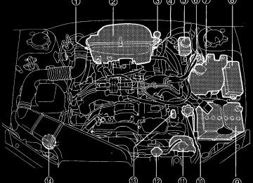
Engine compartment overview
B 2.5 liter models
1 Manual transmission oil level gauge (MT) (page 11-23) or Differential gear oil level gauge (AT) (page 11-26)
2 Air cleaner element
(page 11-18)
3 Clutch fluid reservoir
(page 11-32)
4 Automatic
transmission level gauge (page 11-24)
5 Brake fluid reservoir
(page 11-30)
6 Fuel filter
HBB036BB
7 Windshield washer tank
(page 11-42)
8 Fuse box (page 11-46) 9 Battery (page 11-45) Q Engine oil filler cap
(page 11-9)
W Engine coolant reservoir
(page 11-15)
11
fluid
E Radiator cap (page 11-15) R Engine oil level gauge
(page 11-9)
T Power steering fluid reservoir
(page 11-29)
– CONTINUED –
11-7
Legacy U.S.A..(ENG.)A2280BE–A
B 3.0 liter models
1 Air cleaner element
(page 11-18)
2 Differential gear oil level gauge
(AT) (page 11-26)
3 Automatic
transmission level gauge (page 11-24)
4 Brake fluid reservoir
(page 11-30)
5 Fuel filter 6 Windshield washer tank
(page 11-42)
11-8
HBB058BB
7 Fuse box (page 11-46) 8 Battery (page 11-45) 9 Engine coolant reservoir
(page 11-15)
fluid
Q Engine oil filler cap
(page 11-9)
W Engine oil level gauge
(page 11-9)
E Radiator cap (page 11-15) R Power steering fluid reservoir
(page 11-29)
Legacy U.S.A..(ENG.)A2280BE–A
Maintenance and service
Engine oil
B Checking the oil level Check the engine oil level at each fuel stop.
HBB004BA
HSB008BB
1. Park the vehicle on a level surface and stop the engine. 2. Pull out the dipstick, wipe it clean, and insert it again. 3. Be sure the dipstick is correctly inserted until it stops with the graphic symbol on its top appearing as shown in the illustra- tion. 4. Pull out the dipstick again and check the oil level on it. If it is below the lower level, add oil to bring the level up to the upper level.
CAUTION
Use only engine oil with the recommended grade and viscosity.
If you check the oil level just after stopping the engine, wait a few min- utes for the oil to drain back into the oil pan before checking the level. Just after driving or while the engine is warm, the engine oil level reading may be in a range between the upper level and the notch mark. This is caused by thermal expansion of the engine oil. To prevent overfilling the engine oil, do not add any additional oil above the upper level when the engine is cold.
11
– CONTINUED –
11-9
Legacy U.S.A..(ENG.)A2280BE–A
B Changing the oil and oil filter Change the oil and oil filter according to the maintenance schedule in the “Warranty and Maintenance Booklet”. The engine oil and oil filter must be changed more frequently than listed in the maintenance schedule when driving on dusty roads, when short trips are frequently made, or when driving in extremely cold whether.
1. Warm up the engine by letting the engine idle for about 10 minutes to ease draining the engine oil. 2. Park the vehicle on a level surface and stop the engine. 3. Remove the oil filler cap.
HBB005BB
4. Drain out the engine oil by removing the drain plug while the en- gine is still warm. The used oil should be drained into an appropriate container and disposed of properly.
WARNING
Be careful not to burn yourself with hot engine oil.
5. Wipe the seating surface of the drain plug with a clean cloth and tighten it securely with a new sealing washer after the oil has com- pletely drained out.
11-10
Legacy U.S.A..(ENG.)A2280BE–A
Maintenance and service
HBB051BB
HBB054BA
HBB055BA
6. Remove three clips at the front of the cover under the oil filter. 7. Slide the cover toward the vehicle front to remove it. 8. Remove the oil filter with an oil filter wrench. 9. Before installing a new oil filter, apply a thin coat of engine oil to the seal. 10. Clean the rubber seal seating area of the lower crank case and install the oil filter by hand turning. Be careful not to twist or damage the seal. 11. Tighten it approximately two-thirds of a turn after the seal makes contact with the lower crank case.
CAUTION
Never over tighten the oil filter because that can result in an oil leak.
– CONTINUED –
11-11
11
Legacy U.S.A..(ENG.)A2280BE–A
12. Reinstall the cover under the oil filter. 13. Pour the specified amount of engine oil through the filler neck.
Oil capacity:
2.5 liter models: 4.2 US qt (4.0 liters, 3.5 Imp qt) 3.0 liter models: 6.0 US qt (5.7 liters, 5.0 Imp qt)
14. Start the engine and make sure that no oil leaks appear around the filter’s rubber seal. 15. Run the engine until it reaches the normal operating temperature. Then stop the engine and wait a few minutes to allow the oil drain back. Check the oil level again and if necessary, add more engine oil.
B Recommended grade and viscosity
CAUTION
Use only engine oil with the recommended grade and viscosity.
Oil grade: API classification SJ or SH with the words “ENERGY CONSERVING II” (if you cannot obtain the oil with SJ or SH grade, you may use SG grade oil.) or the new API certification mark (Starburst mark) dis- played on the container.
New API Certification Mark (Starburst Mark)
API Service label
1 Indicates the oil quality by API designations 2 Indicates the SAE oil viscosity grade 3 Indicates that the oil has fuel saving capabilities
11-12
Legacy U.S.A..(ENG.)A2280BE–A
Maintenance and service
In choosing an oil, you want the proper quality and viscosity, as well as one that will add to fuel economy. The following table lists the rec- ommended viscosities and applicable temperatures. When adding oil, different brands may be used together as long as they are the same API classification and SAE viscosity as those rec- ommended by SUBARU.
Engine oil viscosity (thickness) affects fuel economy. Oils of lower vis- cosity provide better fuel economy. However, in hot weather, oil of higher viscosity is required to properly lubricate the engine.
SAE viscosity numbr and applicable temperature
OM-H2756
B Recommended grade and viscosity under severe driving
conditions
If the vehicle is used in desert areas, in areas with very high tempera- tures, or used for heavy-duty applications such as a towing a trailer, use of oil with the following grade and viscosities is recommended.
API classification SJ or SH: SAE viscosity No.: 30, 40, 10W-50, 20W-40, 20W-50
11
– CONTINUED –
11-13
Legacy U.S.A..(ENG.)A2280BE–A
Cooling system
WARNING
Never attempt to remove the radiator cap until the engine has been shut off and has cooled down completely. Since the coolant is under pressure, you may suffer serious burns from a spray of boiling hot coolant when the cap is removed.
CAUTION
D The cooling system has been filled at the factory with a high quality, corrosion-inhibiting, year-around coolant which provides protection against freezing down to –33°F (–36°C). For adding, use genuine SUBARU coolant or an equivalent: a mixture of 50% soft water and 50% ethylene-glycol basis coolant. Use of improp- er coolants may result in corrosion in the cooling system. It is im- portant to maintain protection against freezing and corrosion, even if freezing temperatures are not expected. Never mix differ- ent kinds of coolant. D Do not splash the engine coolant over painted parts. The alco- hol contained in the engine coolant may damage the paint sur- face.
B Hose and connections Your vehicle employs an electric cooling fan which is thermostatically controlled to operate when the engine coolant reaches a specific tem- perature. If the radiator cooling fan does not operate even when the engine coolant temperature gauge exceeds the normal operating range, the cooling fan circuit may be defective. Check the fuse and replace it if necessary. If the fuse is not blown, have the cooling system checked by your SUBARU dealer. If frequent addition of coolant is necessary, there may be a leak in the engine cooling system. It is recommended that the cooling system and connections be checked for leaks, damage, or looseness.
11-14
Legacy U.S.A..(ENG.)A2280BE–A
Maintenance and service
J Engine coolant
B Checking the coolant level Check the coolant level at each fuel stop.
HBB004FB
1. Check the coolant level on the outside of the reservoir while the engine is cool. 2. If the level is close to or lower than the “LOW” level mark, add coolant up to the “FULL” level mark. If the reserve tank is empty, re- move the radiator cap and refill as required.
Rubber gaskets
11
HG0115
3. After refilling the reserve tank and the radiator, reinstall the caps and check that the rubber gaskets inside the radiator cap are in the proper position.
– CONTINUED –
11-15
Legacy U.S.A..(ENG.)A2280BE–A
B Changing the coolant
WARNING
Never attempt to remove the radiator cap until the engine has been shut off and has cooled down completely. Since the coolant is under pressure, you may suffer serious burns from a spray of boiling hot coolant when the cap is removed.
Change the engine coolant using the following procedures according to the maintenance schedule in the “Warranty and Maintenance Book- let”. 1. Remove the under cover. 2. Place a proper container under the drain plug and loosen the drain plug.
HBB006BB
HBB059BB
3. Loosen the radiator cap to drain the coolant from the radiator. Then drain the coolant from the reserve tank. Tighten the drain plug secure- ly.
11-16
Legacy U.S.A..(ENG.)A2280BE–A
Maintenance and service
HBB007BB
HBB004FB
4. Slowly pour the coolant and fill to the radiator filler neck and to the reserve tank’s “FULL” level mark. Do not pour the coolant too quickly, as this may lead to insufficient air bleeding and trapped air in the sys- tem.
Coolant capacity:
2.5 liter models
3.0 liter models
MT. 7.2 US qt (6.8 liters, 6.0 Imp qt) AT. 7.1 US qt (6.7 liters, 5.9 Imp qt) 8.1 US qt (7.7 liters, 6.7 Imp qt)
Rubber gaskets
11
HG0115
5. Put the radiator cap back on and tighten firmly. At this time, make sure that the rubber gasket in the radiator cap is correctly in place. 6. Start and run the engine for more than five minutes at 2,000 to 3,000 rpm.
– CONTINUED –
11-17
Legacy U.S.A..(ENG.)A2280BE–A
7. Stop the engine and wait until the coolant cools down (122 to 140°F [50 to 60°C]). If there is any loss of coolant, add coolant to the radiator’s filler neck and to the reserve tank’s “FULL” level. 8. Put the radiator cap and reservoir cap back on and tighten firmly.
Air cleaner element
WARNING
Do not operate the engine with the air cleaner element removed. The air cleaner element not only filters intake air but also stops flames if the engine backfires. If the air cleaner element is not installed when the engine backfires, you could be burned.
The air cleaner element functions as a filter screen. When the element is perforated or removed, engine wear will be excessive and engine life shortened.
The air cleaner element is a viscous type. It is unnecessary to clean or wash the element.
B Replacing the air cleaner element Replace the air cleaner element according to the maintenance sched- ule in the “Warranty and Maintenance Booklet”. Under extremely dusty conditions, replace it more frequently. It is recommended that you always use genuine SUBARU parts.
11-18
Legacy U.S.A..(ENG.)A2280BE–A
n 2.5 liter models
Maintenance and service
Bolt
Air cleaner element
HBA002BB
HBA003BB
1. Remove the bolt securing the rear air cleaner element case. 2. Unsnap the three clamps holding the rear air cleaner element case. 3. Separate the rear air cleaner element case from the front air clean- er element case and remove the air cleaner element. 4. Clean the inside of the front and rear air cleaner element cases with a damp cloth and install a new air cleaner element. 5. Insert the four projections on the rear air cleaner element case into the slits on the front air cleaner element case and snap the three clamps on the rear air cleaner element case and then tighten the bolt.
n 3.0 liter models
11
1. Unsnap the two clamps holding the air cleaner case cover.
HBB056BA
– CONTINUED –
11-19
Legacy U.S.A..(ENG.)A2280BE–A
2. Open the air cleaner case cover and remove the air cleaner ele- ment. 3. Clean the inside of the air cleaner cover and case with a damp cloth and install a new air cleaner element.
HBB057BA
To install the air cleaner case cover, insert two projections on the air cleaner case into the slits on the air cleaner case cover and then snap the two clamps on the air cleaner case cover.
Spark plugs
CAUTION
D When disconnecting the spark plug cables, always grasp the spark plug cap, not the cables. D Make sure the cables are replaced in the correct order.
11-20
Legacy U.S.A..(ENG.)A2280BE–A
Maintenance and service
HBA004BA
It may be difficult to replace the spark plugs. It is recommended that you have the spark plugs replaced by your SUBARU dealer.
The spark plugs should be replaced according to the maintenance schedule in the “Warranty and Maintenance Booklet”.
B Recommended spark plugs
2.5 liter models:
RC10YC4 (Champion) RC8YC4 (Champion) BKR6E-11 (NGK) K20PR-U11 (NIPPON DENSO) 3.0 liter models: PLFR6A-11 (NGK)
11
– CONTINUED –
11-21
Legacy U.S.A..(ENG.)A2280BE–A
Drive belts
The alternator, power steering pump, and air conditioner compressor de- pend on drive belts. Satisfactory performance requires that belt tension be correct.
B 2.5 liter models
HGA005BB
Deflection
in (mm)
New belt
0.28 — 0.35
(7.0 — 9.0)0.30 — 0.33
(7.5 — 8.5)Used belt
0.35 — 0.43
(9.0 — 11.0)0.35 — 0.40
(9.0 — 10.0)To check belt tension, place a straightedge (ruler) across two adja- cent pulleys and apply a force of 22 lb (98 N, 10 kg) midway between the pulleys by using a spring scale. Belt deflection should be the amount specified.
B 3.0 liter models It is unnecessary to check belt tension periodically because your engine is equipped with an automatic belt tension adjuster. However, replacement of the belt should be done according to the maintenance
11-22
Legacy U.S.A..(ENG.)A2280BE–A
Maintenance and service
schedule in the “Warranty and Maintenance Booklet”. Consult your SUBARU dealer for replacement. If a belt is loose, cracked, or worn, contact your SUBARU dealer.
Manual transmission oil
B Checking the oil level Check the oil level monthly. 1. Park the vehicle on a level surface and stop the engine.
Upper level
Lower level
HBB004DB
OM-H0210
2. Pull out the dipstick, wipe it clean, and insert it again. 3. Pull out the dipstick again and check the oil level on it. If it is below the lower level, add oil through the dipstick hole to bring the level up to the upper level.
B Recommended grade and viscosity Each oil manufacturer has its own base oils and additives. Never use different brands together.
11
Oil grade: API classification GL-5
– CONTINUED –
11-23
Legacy U.S.A..(ENG.)A2280BE–A
SAE viscosity No. and Applicable Temperature
OM-H0205
Automatic transmission fluid
B Checking the fluid level The automatic transmission fluid expands largely as its temperature rises; the fluid level differs according to fluid temperature. Therefore, there are two different scales for checking the level of hot fluid and cold fluid on the dipstick.
Though the fluid level can be checked without warming up the fluid on the “COLD” range, we recommend checking the fluid level when the fluid is at operating temperature.
n Checking the fluid level when the fluid is hot Check the fluid level monthly. 1. Drive the vehicle several miles to raise the temperature of the transmission fluid up to normal operating temperature; 140 to 176°F (60 to 80°C) is normal. 2. Park the vehicle on a level surface and set the parking brake. 3. First shift the selector lever in each position. Then shift it in the “P” position, and run the engine at idling speed.
11-24
Legacy U.S.A..(ENG.)A2280BE–A
Maintenance and service
Upper level
Lower level
COLD range
HOT range
Upper level
Lower level
HBB004CB
HBA008BB
4. Pull out the dipstick and check the fluid level on the gauge. If it is below the lower level on the “HOT” range, add the recommended au- tomatic transmission fluid up to the upper level.
n Checking the fluid level when the fluid is cold When the fluid level has to be checked without time to warm up the automatic transmission, check to see that the fluid level is between the lower level and upper level on the “COLD” range. If it is below that range, add fluid up to the upper level. Be careful not to overfill.
B Recommended fluid
“Dexron II” or “Dexron III” Type Automatic Transmission Fluid
11
– CONTINUED –
11-25
Legacy U.S.A..(ENG.)A2280BE–A
Front differential gear oil (AT vehicles)
B Checking the oil level Check the differential oil level monthly.
HBB004EB
Upper level
Lower level
HBA010BB
1. Park the vehicle on a level surface and stop the engine. 2. Pull out the dipstick, wipe it clean, and insert it again. 3. Pull out the dipstick again and check the oil level on it. If it is below the lower level, add oil to bring the level up to the upper level.
B Recommended grade and viscosity Each oil manufacturer has its own base oils and additives. Never use different brands together.
Oil grade: API classification GL-5
11-26
Legacy U.S.A..(ENG.)A2280BE–A
SAE viscosity No. and Applicable Temperature
Maintenance and service
OM-H0212
Rear differential gear oil
B Checking the gear oil level
CAUTION
If the vehicle requires frequent refilling, there may be an oil leak. If you suspect a problem, have the vehicle checked at your SUBARU dealer.
Your vehicle may be equipped with a rear differential protector. The differential protector provides protection to the rear differential assem- bly during off-road use. Removal of the rear differential protector is not required when checking the oil level.
11
– CONTINUED –
11-27
Legacy U.S.A..(ENG.)A2280BE–A
Filler hole
Oil level
Drain hole
HB0077
Filler hole
Drain hole
HB0078
Remove the plug from the filler hole and check the oil level. The oil level should be kept even with the bottom of the filler hole. If the oil level is below the bottom edge of the hole, add oil through the filler hole to raise the level.
B Recommended grade and viscosity Each oil manufacturer has its own base oils and additives. Never use different brands together.
Oil grade: API classification GL-5
SAE viscosity No. and Applicable Temperature
OM-H0205
11-28
Legacy U.S.A..(ENG.)A2280BE–A
Power steering fluid
B Checking the fluid level
Maintenance and service
WARNING
Be careful not to burn yourself because the fluid may be hot.
CAUTION
D When power steering fluid is being added, use only clean fluid, and be careful not to allow any dirt into the tank. And never use different brands together. D Avoid spilling fluid when adding it in the tank.
The power steering fluid expands greatly as its temperature rises; the fluid level differs according to fluid temperature. Therefore, the reser- voir tank has two different checking ranges for hot and cold fluids.
Check the power steering fluid level monthly. 1. Park the vehicle on a level surface, and stop the engine. 2. Check the fluid level of the reservoir tank. When the fluid is hot after the vehicle has been run: Check that the oil level is between “HOT MIN” and “HOT MAX” on the surface of the reservoir tank. When the fluid is cool before the vehicle is run: Check that the oil level is between “COLD MIN” and “COLD MAX” on the surface of the res- ervoir tank. 3. If the fluid level is lower than the applicable “MIN” line, add the recommended fluid as necessary to bring the level between the “MIN” and “MAX” line.
11
– CONTINUED –
11-29
Legacy U.S.A..(ENG.)A2280BE–A
Reservoir tank
Specified range
Specified range
HBB030BB
HBB031BB
If the fluid level is extreme low, it may indicate possible leakage. Con- sult your SUBARU dealer for inspection.
B Recommended fluid
“Dexron IIE” or “Dexron III” Type Automatic Transmission Fluid
Brake fluid
B Checking the fluid level
WARNING
D Never let brake fluid contact your eyes because brake fluid can be harmful to your eyes. If brake fluid gets in your eyes, immedi- ately flush them thoroughly with clean water. For safety, when performing this work, wearing eye protection is advisable. D Brake fluid absorbs moisture from the air. Any absorbed mois- ture can cause a dangerous loss of braking performance. D If the vehicle requires frequent refilling, there may be a leak. If you suspect a problem, have the vehicle checked at your SUBARU dealer.
11-30
Legacy U.S.A..(ENG.)A2280BE–A
Maintenance and service
CAUTION
D Never use different brands of brake fluid together. D When adding brake fluid, be careful not to allow any dirt into the reservoir. D Never splash the brake fluid over painted surfaces or rubber parts. Alcohol contained in the brake fluid may damage them.
Check the fluid level monthly.
“MAX” level mark
“MIN” level mark
HBB004GB
Check the fluid level on the outside of the reservoir. If the level is be- low “MIN”, add the recommended brake fluid to “MAX”. Use only brake fluid from a sealed container.
B Recommended brake fluid
FMVSS No. 116, fresh DOT 3 or 4 brake fluid
11
– CONTINUED –
11-31
Legacy U.S.A..(ENG.)A2280BE–A
Clutch fluid (MT vehicles)
B Checking the fluid level
WARNING
Never let clutch fluid contact your eyes because clutch fluid can be harmful to your eyes. If clutch fluid gets in your eyes, immedi- ately flush them thoroughly with clean water. For safety, when performing this work, wearing eye protection is advisable.
CAUTION
D Clutch fluid absorbs moisture from the air. Any absorbed moisture can cause improper clutch operation. D If the vehicle requires frequent refilling, there may be a leak. If you suspect a problem, have the vehicle checked at your SUBARU dealer. D Never use different brands of clutch fluid together. D When clutch fluid is added, be careful not to allow any dirt into the tank.
Check the fluid level on the outside of the reservoir. If the level is below “MIN” level mark, add the recommended clutch fluid to “MAX” level mark. Use only clutch fluid from a sealed container.
“MAX” level mark
“MIN” level mark
11-32
HBB004HB
Legacy U.S.A..(ENG.)A2280BE–A
Maintenance and service
B Recommended clutch fluid
FMVSS No. 116, fresh DOT 3 or 4 brake fluid
Brake booster
If the brake booster does not operate as described below, have it checked by your SUBARU dealer. 1. With the engine off, depress the brake pedal several times, applying the same pedal force each time. The distance the pedal travels should not vary. 2. With the brake pedal depressed, start the engine. The pedal should move slightly down to the floor. 3. With the brake pedal depressed, stop the engine and keep the pedal depressed for 30 seconds. The pedal height should not change. 4. Start the engine again and run for about one minute then turn it off. Depress the brake pedal several times to check the brake booster. Brake booster operates properly if the pedal stroke decreases with each depression.
11
– CONTINUED –
11-33
Legacy U.S.A..(ENG.)A2280BE–A
Brake pedal
Check the brake pedal free play and reserve distance according to the maintenance schedule in the “Warranty and Maintenance Booklet”.
B Checking the brake pedal free play
0.04 — 0.12 in (1.0 — 3.0 mm)
OM-H0224
Stop the engine and firmly depress the brake pedal several times. Lightly press the brake pedal down with one finger to check the free play with a force of less than 2 lb (10 N, 1 kg). If the free play is not within proper specification, contact your SUBARU dealer.
B Checking the brake pedal reserve distance
More than 2.56 in (65 mm)
Depress the pedal with a force of approximately 66 lb (294 N, 30 kg)
OM-H0225
11-34
Legacy U.S.A..(ENG.)A2280BE–A
Maintenance and service
and measure the distance between the upper surface of the pedal pad and the floor. When the measurement is smaller than the specification, or when the pedal does not operate smoothly, contact with your SUBARU dealer.
Clutch pedal (Manual transmission vehicles)
Check the clutch pedal free play and reserve distance according to the maintenance schedule in the “Warranty and Maintenance Booklet”.
B Checking the clutch function Check the clutch engagement and disengagement. 1. With the engine idling, check that there are no abnormal noises when the clutch pedal is depressed, and that shifting into 1st or re- verse feels smooth. 2. Start the vehicle by releasing the pedal slowly to check that the en- gine and transmission smoothly couple without any sign of slippage.
B Checking the clutch pedal free play
0.16 — 0.51 in (4.0 — 13.0 mm)
OM-H0224
11
Lightly press the clutch pedal down with your finger until you feel re- sistance, and check the free play. If the free play is not within proper specification, contact your SUBARU dealer.
– CONTINUED –
11-35
Legacy U.S.A..(ENG.)A2280BE–A
Replacement of brake pad and lining
CAUTION
If you continue to drive despite the scraping noise from the audi- ble brake pad wear indicator, it will result in the need for costly brake rotor repair or replacement.
OM-H0163
The front disc brakes and the right rear disc brake have an audible wear indicators on the brake pads. If the brake pads wear close to their ser- vice limit, the wear indicator makes a very audible scraping noise when the brake pedal is applied.
If you hear this scraping noise each time you apply the brake pedal, have the brake pads serviced by your SUBARU dealer as soon as pos- sible.
B Breaking-in of new brake pads and linings When replacing the brake pad or lining, use only genuine SUBARU parts. After replacement, the new parts must be broken in as follows:
n Brake pad and lining While maintaining a speed of 30 to 40 mph (50 to 65 km/h), step on the brake pedal lightly. Repeat this five or more times.
11-36
Legacy U.S.A..(ENG.)A2280BE–A
Maintenance and service
n Parking brake lining
WARNING
A safe location and situation should be selected for break-in driv- ing.
CAUTION
Pulling the parking brake lever too forcefully may cause the rear wheels to lock. To avoid this, be certain to pull the lever up slowly and gently.
1. Drive the vehicle at a speed of about 22 mph (35 km/h). 2. With the parking brake release button pushed in, pull the parking brake lever SLOWLY and GENTLY. (Pulling with a force of approxi- mately 33 lb [147 N, 15 kg].) 3. Drive the vehicle for about 220 yards (200 meters) in this condition. 4. Wait 5 to 10 minutes for the parking brake to cool down. Repeat this procedure. 5. Check the parking brake stroke. If the parking brake stroke is out of the specified range, adjust it by turning the adjusting nut located on the parking brake lever.
Parking brake stroke: 7 — 8 notches / 44 lb (196 N, 20 kg)
Parking brake stroke
11
Check the parking brake stroke according to the maintenance schedule in the “Warranty and Maintenance Booklet”. When the parking brake is properly adjusted, braking power is fully applied by pulling the lever up seven to eight notches gently but firmly (about 44 lb, 196 N, 20 kg). If the parking brake lever stroke is not within the specified range, have the brake system checked and adjusted at your SUBARU dealer.
– CONTINUED –
11-37
Legacy U.S.A..(ENG.)A2280BE–A
HB4001CB
Tires and wheels
WARNING
D When replacing a tire, make sure you use only the same size, circumferences, construction, brand, speed symbol and load in- dex as the original tires listed on the tire placard. Using other sizes, circumferences or construction may result in severe me- chanical damage to the drivetrain of your vehicle and may affect ride, handling, braking, speedometer/odometer calibration, and clearance between the body and tires. It also may be dangerous and lead to loss of vehicle control. D Do not use a combination of radial, belted bias or bias tires since it may cause dangerous handling characteristics and lead to an accident. D Do not let air out of warm tires to adjust pressure. Doing so will result in low tire pressure.
The tires should be checked frequently for proper tire pressure, wear, and cuts.
11-38
Legacy U.S.A..(ENG.)A2280BE–A
Maintenance and service
J Tire pressure For the best balance between fuel economy, tire life, ride comfort, and handling, tire pressure should be maintained in accordance with specifi- cations. Check the tire pressure when the tires are cold. Cold means that the vehicle has been parked for three hours or has been driven less than 1 mile (1.6 km).
HB0382
The recommended tire pressure and sizes are provided on the tire plac- ard, which is located under the door latch on the driver’s side.
J Tire rotation Tire wear will vary with each wheel. To increase the life of tires and keep wear uniform, it is best to rotate them every 7,500 mile (12,500 km). When rotating tires, replace any unevenly worn or damaged tire. After rotating the tires, adjust tire pressure and be sure to check wheel nut tightness.
11
– CONTINUED –
11-39
Legacy U.S.A..(ENG.)A2280BE–A
New tread Worn tread
Tread wear indicator
OM-H0230
OM-H0231
A tire should be replaced when the tread wear indicator appears as a solid band across the tread. The indicators appear when the remaining tread has been worn to 0.063 in (1.6 mm) or less.
J Wheel covers
B Removing the wheel cover
HGA012BB
Insert the wheel nut wrench into the notch provided, and pry the wheel cover off.
11-40
Legacy U.S.A..(ENG.)A2280BE–A
B Installing the wheel cover
Maintenance and service
HGA013BA
Align the valve with the valve hole in the cover, then fit the cover on the wheel by tapping your hand evenly around the circumference of the cover.
NOTE When any of the wheels is removed and replaced for tire rotation or to change a flat tire, always check the tightness of the wheel nuts after driving approximately 600 miles (1,000 km). If any nut is loose, tighten it to the specified torque.
Aluminum wheels (If equipped)
Aluminum wheels can be scratched and damaged easily. Handle them carefully to maintain their appearance, performance, and safety.
D When any of the wheels is removed and replaced for tire rotation or to change a flat, always check the tightness of the wheel nuts after driving approximatly 600 miles (1,000 km). If any nut is loose, tighten it to the specified torque. D Never apply oil to the threaded parts, wheel nuts, or tapered surface of the wheel. D Never let the wheel rub against sharp protrusions or curbs. D Be sure to fit tire chains on uniformly and completely around the tire, otherwise the chains may scratch the wheel.
– CONTINUED –
11-41
11
Legacy U.S.A..(ENG.)A2280BE–A
D When wheel nuts, balance weights, or the center cap replaced, be sure to replace them with genuine SUBARU parts designed for aluminum wheels.
Windshield washer fluid
CAUTION
Never use engine coolant as washer fluid because it could cause paint damage.
Check the level of the washer fluid at each fuel stop. If the level is low, fill the fluid up to the neck of the reservoir. Use windshield washer fluid. If windshield washer fluid is unavailable use clean water. In areas where water freezes in winter, use an anti-freeze type windshield washer fluid. SUBARU Windshield Washer Fluid contains 58.5% methyl alcohol and 41.5% surfactant, by volume. Its freezing temperature varies according to how much it is diluted, as indicated below.
Washer Fluid Concentration
Freezing Temperature
30% 50% 100%
10.4°F (–12°C) –4 °F (–20°C) –49°F (–45°C)
HBB004IA
11-42
Legacy U.S.A..(ENG.)A2280BE–A
Maintenance and service
Replacement of windshield wiper blades
Grease, wax, insects, or other materials on the windshield or the wiper blade results in jerky wiper operation and streaking on the glass. If you cannot remove the streaks after operating the windshield washer or if the wiper operation is jerky, clean the outer surface of the windshield (or rear window) and the wiper blades using a sponge or soft cloth with a neutral detergent or mild-abrasive cleaner. After cleaning, rinse the windshield and wiper blades with clean water. The windshield is clean if beads do not form when you rinse the windshield with water.
CAUTION
Do not clean the wiper blades with gasoline or a solvent, such as paint thinner or benzene. This will cause deterioration of the wiper blades.
If you cannot eliminate the streaking even after following this method, replace the wiper blades using the following procedures: 1. Raise the wiper arm off the windshield. 2. Remove the wiper blade assembly by holding its pivot area and push- ing it in the direction shown by the arrow while depressing the wiper blade stopper.
11
Stopper
HS0190
3. Grasp the locked end of the blade rubber assembly and pull it firmly until the stoppers on the rubber are free of the metal support.
– CONTINUED –
11-43
Legacy U.S.A..(ENG.)A2280BE–A
Metal support
HS0191
4. If the new blade rubber is not provided with two metal spines, remove the metal spines from the old blade rubber and install them in the new blade rubber.
Metal spines
HS0192
5. Align the claws of the metal support with the grooves in the rubber and slide the blade rubber assembly into the metal support until it locks. Be sure to position the claws at the end of the metal support between the stoppers on the rubber as shown. If the rubber is not retained properly, the wiper blade may scratch the windshield.
11-44
Legacy U.S.A..(ENG.)A2280BE–A
Maintenance and service
Stopper
HS0193
HS0194
6. Install the wiper blade assembly to the wiper arm. Make sure that it locks in place. 7. Lower the wiper arm.
Battery
WARNING
D Before beginning work on or near any battery, be sure to extin- guish all cigarettes, matches, and lighters. Never expose a bat- tery to an open flame or electric sparks. Batteries give off a gas which is highly flammable and explosive. D For safety, in case an explosion does occur, wear eye protec- tion or shield your eyes when working near any battery. Never lean over a battery. D Do not let battery fluid contact eyes, skin, fabrics, or paint be- cause battery fluid is a corrosive acid. If battery fluid gets on your skin or in your eyes, immediately flush the area with water thor- oughly. Seek medical help immediately if acid has entered the eyes. If battery fluid is accidentally swallowed, immediately drink a large amount of milk or water, and seek medical attention immediately. D To lessen the risk of sparks, remove rings, metal watchbands,
– CONTINUED –
11-45
11
Legacy U.S.A..(ENG.)A2280BE–A
and other metal jewelry. Never allow metal tools to contact the positive battery terminal and anything connected to it WHILE you are at the same time in contact with any other metallic portion of the vehicle because a short circuit will result. D Keep everyone including children away from the battery. D Charge the battery in a well-ventilated area.
CAUTION
Never use more than 10 amperes when charging the battery be- cause it will shorten battery life.
It is unnecessary to periodically check the battery fluid level or periodi- cally refill with distilled water.
Fuses
CAUTION
Never replace a fuse with one having a higher rating or with mate- rial other than a fuse because serious damage or a fire could re- sult.
HBB008DA
HB8003CA
The fuses are designed to melt during an overload to prevent damage to the wiring harness and electrical equipment. The fuses are located in
11-46
Legacy U.S.A..(ENG.)A2280BE–A
Maintenance and service
two fuse boxes. The one is located under the instrument panel behind the coin tray on the driver’s seat side. The other one is housed in the engine compartment. The fuse puller and spare fuses are stored in the main fuse box cover in the engine compartment. If any lights, accessories or other electrical controls do not operate, in- spect the corresponding fuse. If a fuse has blown, replace it.
Good
Blown
Fuse puller
Spare fuses
HS0204
HS0208
1. Turn the ignition switch to the “LOCK” position and turn off all electri- cal accessories. 2. Remove the cover. (For behind the coin tray: open the coin tray and pull it horizontally to remove it.) 3. Determine which fuse may be blown. The back side of each fuse box cover and the “Fuse and circuits” section in chapter 12 in this manual show the circuit for each fuse.
Fuse puller
11
HS0207
– CONTINUED –
11-47
Legacy U.S.A..(ENG.)A2280BE–A
4. Pull out the fuse with the fuse puller. 5. Inspect the fuse. If it has blown, replace it with a spare fuse of the same rating. 6. If the same fuse blows again, this indicates that its system has a problem. Contact your SUBARU dealer for repairs.
Main fuse and fusible link
HB8003CB
The main fuses and fusible link are designed to melt during an overload to prevent damage to the wiring harness and electrical equipment. Check the main fuses and fusible link if any electrical component fails to operate (except the starter motor) and other fuses are good. A melted main fuse or fusible link must be replaced. Use only replacements with the same specified rating as the melted main fuse or fusible link. If a main fuse or fusible link blows after it is replaced, have the electrical sys- tem checked by your nearest SUBARU dealer.
Installation of accessories
Always consult your SUBARU dealer before installing fog lights or any other electrical equipment in your vehicle. Such accessories may cause the electronic system to malfunction if they are incorrectly installed or if they are not suited for the vehicle.
11-48
Legacy U.S.A..(ENG.)A2280BE–A
Replacing bulbs
Maintenance and service
1 Headlight
GT and OUTBACK models
Low beam High beam
Except GT and OUTBACK models
2 Front turn signal 3 Spot light 4 Dome light 5 Door step light 6 Front turn signal light/
HB5019EB
Wattage
Bulb No.
H1
12V–55W 12V–60W 9005 (HB3) 12V–60/55W 9007 (HB5) 12V–27W 12V–8W 12V–8W 12V–3.4W1156NA (Amber) — — —
11
parking and front side marker light
12V–27/8W
1157NA (Amber)
7 Front fog light
Except OUTBACK OUTBACK
12V–55W 12V–51W
H3
9006 (HB4)– CONTINUED –
11-49
Legacy U.S.A..(ENG.)A2280BE–A
HBF013FC
8 Backup light
Sedan Station wagon
9 Luggage area light Q High mount stop light
Sedan Station wagon
W Rear turn signal light
Sedan Station wagon
E Brake/tail light
Sedan Station wagon R Licence plate light
Sedan Station wagon T Trunk room light
11-50
HBB033BC
Wattage
Bulb No.
12V–27W 12V–27W 12V–13W
12V–18W 12V–13W
12V–21W 12V–21W
3156K 1156
—921
912— R2172 7440
12V–27/8W 12V–27/8W
3157K 1157
12V–5W 12V–3.8W or 5W 194 or 168
12V–5WW5W
168
Legacy U.S.A..(ENG.)A2280BE–A
Maintenance and service
J Headlight
CAUTION
Halogen headlight bulbs become very hot while in use. If you touch the bulb surface with bare hands or greasy gloves, finger prints or grease on the bulb surface develop into hot spots, caus- ing the bulb to break. If there are finger prints or grease on the bulb surface, wipe them away with a soft cloth moistened with al- cohol.
NOTE If headlight aiming is required, consult your SUBARU dealer for proper adjustment of the headlight aim.
B For GT and OUTBACK models
Remove the headlight bulb cover, by turning it counterclockwise.
HBB039BA
HBB040BB
11
– CONTINUED –
11-51
Legacy U.S.A..(ENG.)A2280BE–A
n Low beam light bulbs
HBB041BB
HBB042BA
1. Disconnect the electrical connector for the black cable. 2. Remove the retainer spring. 3. Replace the bulb, then set the retainer spring securely. 4. Reconnect the electrical connector for black cable. 5. Install the headlight bulb cover.
n High beam light bulbs
HBB043BA
HBB044BB
1. Disconnect the electrical connector from the bulb. 2. Remove the bulb from the headlight assembly by turning it coun- terclockwise. 3. Replace the bulb with new one. 4. Reconnect the electrical connector. At this time, use care not to touch the bulb surface.
11-52
Legacy U.S.A..(ENG.)A2280BE–A
Maintenance and service
5. To install the bulb to the headlight assembly, turn it clockwise until it clicks. 6. Install the headlight bulb cover. B Except GT and OUTBACK models
HBB045BB
HBB046BA
1. Disconnect the electrical connector while pressing the lock release tab. 2. Remove the bulb holder from the headlight assembly by turning it counterclockwise. 3. Remove the bulb from the headlight assembly. 4. Install the new bulb. 5. Install the bulb holder in the headlight assembly by turning it clock- wise until it locks. 6. Remove the electrical connector.
J Front fog light (if equipped) It may be difficult to replace the bulbs. Have your SUBARU dealer replace the bulbs if necessary.
11
J Front turn signal light, parking light and side marker
light
The headlight assembly must be removed before the front turn signal light and parking light bulbs can be replaced. When the headlight as- sembly has been removed and then reinstalled, it may become neces- sary to make a headlight aiming adjustment. After a bulb has been re- placed, it is recommended that the headlight aiming adjustment be
– CONTINUED –
11-53
Legacy U.S.A..(ENG.)A2280BE–A
made at a SUBARU dealer.
HBB016BA
1. Remove the headlight assembly mounting screws located at the top of and the front of the headlight assembly using a phillips screwdriver or an open-end wrench. 2. Move the headlight assembly forward.
HBB039CB
HBB020BA
3. Remove the bulb socket from the headlight assembly by turning it counterclockwise. 4. Remove the bulb from the socket by pushing it and turning counter- clockwise. Install a new bulb in the socket. 5. Set the bulb socket into the headlight assembly and turn it clockwise until it locks. 6. Set the headlight assembly into the vehicle body. Tighten the mount- ing screws.
11-54
Legacy U.S.A..(ENG.)A2280BE–A
J Rear combination lights
B Sedan
Maintenance and service
HBF014DA
HBB034BC
HBB035BB
1. Open the trunk lid. 2. Open the rear combination light cover. For covers on the trunk lid: Unlatch the cover by pushing the knob and open the cover. For covers on the trunk wall: Unlatch the cover by moving the knob upward and open the cover. 3. Remove the bulb socket from the light assembly by turning it coun- terclockwise. 4. Remove the bulb from the socket. Rear turn signal light: Remove the bulb from the socket by pushing it and turning it counterclockwise. Others: Pull the bulb out of the socket.
– CONTINUED –
11-55
11
Legacy U.S.A..(ENG.)A2280BE–A
5. Install a new bulb in the socket. 6. Set the bulb socket into the rear combination light assembly and turn it clockwise until it locks. 7. Close the cover and latch the clock.
B Station wagon n Brake/tail and rear turn signal light bulbs It may be difficult to replace the bulbs. It is recommended that you have the bulbs replaced by your SUBARU dealer.
HBB021BB
HBB022BB
1. Remove the light bulb replacement service hole covers at two places by prying the edge of the cover with a regular screwdriver. 2. Remove the upper and lower nuts. Then, slide the rear combina- tion lamp assembly to the rear and remove it from the vehicle.
Rear turn signal light bulb
Brake/tail light bulb
HBB047BB
HBB024BB
11-56
Legacy U.S.A..(ENG.)A2280BE–A
Maintenance and service
3. Using a Phillips screwdriver, remove the upper and lower screws that secure the side cover of the rear combination light assembly. 4. Remove the bulb socket from the rear combination light assembly by turning it counterclockwise.
HBB025BA
HBB048BA
5. Remove the bulb from the socket. Turn signal light: Pull the bulb out of the socket. Brake/tail light: Remove the bulb from the socket by pushing it and turning it counterclockwise. 6. Install a new bulb in the socket. 7. Set the bulb holder into the rear combination light assembly and turn it clockwise until it locks. 8. Fit the rear combination light assembly into the vehicle body and tighten the nuts from the interior of the vehicle. 9. Reinstall the light bulb replacement service hole covers.
11
– CONTINUED –
11-57
Legacy U.S.A..(ENG.)A2280BE–A
n Back-up and brake/tail light bulbs
HBB026BC
HBB025BA
1. Unlatch the rear combination light cover by moving the knob up- ward. Open the cover up. 2. Remove the bulb socket from the rear combination light assembly by turning it counterclockwise. 3. Remove the bulb from the socket by pushing it and turning coun- terclockwise. Install a new bulb in the socket. 4. Set the bulb holder into the rear combination light assembly and turn it clockwise until it locks. 5. Close the cover and latch the lock.
J License plate light
HBF013EA
HBB027BA
1. Remove the mounting screws using a phillips screwdriver.
11-58
Legacy U.S.A..(ENG.)A2280BE–A
Maintenance and service
2. Remove the cover and lens. 3. Pull the bulb out of the socket. Install a new bulb. 4. Reinstall the lens and cover. 5. Tighten the mounting screws.
J Dome light, spot light, luggage compartment light
and door step light
HSA005BA
HBB029BA
11
Bulb
HB0386
HBS037AA
1. Remove the lens by prying the edge of the lens with a regular screw- driver. 2. Pull the bulb out of the socket. Install a new bulb. 3. Reinstall the lens.
– CONTINUED –
11-59
Legacy U.S.A..(ENG.)A2280BE–A
J Trunk light
HBF014EA
1. Remove the cover by pulling it out. 2. Pull the bulb out of the socket. Install a new bulb. 3. Reinstall the cover.
J High mount stop light
B Sedan
1. Remove the high mount stop light cover by prying on the edge with a screwdriver. 2. Pull the bulb out of the socket. Install a new bulb. 3. Reinstall the cover.
OM-H2350
11-60
Legacy U.S.A..(ENG.)A2280BE–A
B Station wagon
Maintenance and service
HBB028BA
1. Remove the mounting screw covers by prying on the edge with a screwdriver. 2. Remove the mounting screws using a phillips screwdriver and then remove the high mount stop light cover. 3. Pull the bulb out of the socket. Install a new bulb. 4. Reinstall the cover. 5. Tighten the mounting screws then reinstall the covers.
NOTE Other bulbs may be difficult to replace. Have your SUBARU dealer replace these bulbs if necessary.
11
– CONTINUED –
11-61
Legacy U.S.A..(ENG.)A2280BE–A
Specifications
Specifications Dimensions Engine Electrical system Capacities Tires Wheel alignment Fuses and circuits
. . . . . . . . . . . . . . . . . . . . . . . . . . . . . . . . . . . . . . . . . . . . . . . . . . . . . . . . . . . . . . . . . . . . . . . . . . . . . . . . . . . . . . . . . . . . . . . . . . . . . . . . . . . . . . . . . . . . . . . . . . . . . . . . . . . . . . . . . . . . . . . . . . . . . . . . . . . . . . . . . . . . . . . . . . . . . . . . . . . . . . . . . . . . . . . . . . . . . . . . . . . . . . . . . . . . . . . . . . . . . . . . . . . . . . . . . . . . . . . . . . . . . . . . . . . . . . . . . . . . . . . . . . . . . . . . . . . . . . . . . . . . . . . . . . . . . . . . . . . . . . . . . . . . . . . . . . . . . . . . . . . . . . . . . . . . . . . . . . . . . . . . . . . . . . . . . . . . . . . . . . . . . . . . . . . . . . . . . . . . . . . . . . . . . . . . . . . . . . . . . . . . . . . . . . . . . . . . . . . . . . . . . . . . . . . . . . . . . . . . . . . .
Fuse panel located behind the coin tray Fuse panel located in the engine compartment
. . . . . . . . . . . . . . . . . . . . . . . . . . . . . . . . . . . . . . . . . . . . . . . . . . . . . . . . . . . . . . . . . . . . . . . . . . . . . . . . . . . . . . . . . . . . . . . . . . . . . . .
Bulb chart Vehicle identification
. . . . . . . . . . . . . . . . . . . . . . . . . . . . . . . . . . . . . . . . . . . . . . . . . . . . . . . . . . . . . . . . . . .
. . . . . . . . . . . . . . . . . . . . . . . . . . . . . . . . . . . . . . . . . . . . . . . . . . . .
12-2
12-2
12-3
12-3
12-4
12-4
12-5
12-6
12-6
12-10
12-14
12-1512
Legacy U.S.A..(ENG.)A2280BE–A
Specifications
These specifications are subject to change without notice.
J Dimensions Legacy sedan Overall length Overall width Overall height Ground clearance Front tread Rear tread Wheelbase
Legacy station wagon Overall length Overall width Overall height
Ground clearance Front tread Rear tread Wheelbase
*: With roof rail
OUTBACK sedan Overall length Overall width Overall height Ground clearance Front tread Rear tread Wheelbase
OUTBACK station wagon Overall length Overall width
12-2
184.4 in (4,685 mm) 68.7 in (1,745 mm) 55.7 in (1,415 mm) 6.1 in (155 mm) 57.5 in (1,460 mm) 57.5 in (1,460 mm) 104.3 in (2,650 mm)
187.4 in (4,760 mm) 68.7 in (1,745 mm) 56.6 in (1,435 mm) 59.6 in (1,525 mm)* 6.3 in (160 mm) 57.5 in (1,460 mm) 57.3 in (1,455 mm) 104.3 in (2,650 mm)
184.4 in (4,685 mm) 68.7 in (1,745 mm) 58.3 in (1,480 mm) 7.3 in (185 mm) 57.9 in (1,470 mm) 57.7 in (1,465 mm) 104.3 in (2,650 mm)
187.4 in (4,760 mm) 68.7 in (1,745 mm)
Legacy U.S.A..(ENG.)A2280BE–A
Overall height Ground clearance
2.5 liter models 3.0 liter models
Front tread Rear tread Wheelbase
J Engine 2.5 liter Engine model Engine type
Engine displacement Bore Stroke Compression ratio Firing order
3.0 liter Engine model Engine type
Engine displacement Bore Stroke Compression ratio Firing order
Specifications
62.2 in (1,580 mm)
7.3 in (185 mm) 7.9 in (200 mm) 57.9 in (1,470 mm) 57.7 in (1,465 mm) 104.3 in (2,650 mm)
EJ251
Horizontally opposed, liquid cooled 4 cylinder, 4 stroke gasoline engine 2,457 cc (149.9 cu in.) 3.92 in (99.5 mm) 3.11 in (79.0 mm) 10.0 : 1
1 - 3 - 2 - 4EZ30D Horizontally opposed, liquid cooled 6 cylinder, 4 stroke gasoline engine 2,999 cc (183.0 cu in.) 3.51 in (89.2 mm) 3.15 in (80.0 mm) 10.7 : 1
1 - 6 - 3 - 2 - 5 - 4J Electrical system
2.5 liter Battery type and capacity
Alternator
MT: AT:
55D23L 75D23L 12V-90A
– CONTINUED –
12-3
12
Legacy U.S.A..(ENG.)A2280BE–A
Spark plugs type
RC10YC4 (Champion) RC8YC4 (Champion) BKR6E-11 (NGK) K20PR-U11 (NIPPONDENSO)
3.0 liter Battery type and capacity Alternator Spark plugs type
75D23L 12V-100A PLFR6A-11 (NGK)
J Capacities
Fuel tank Engine oil
2.5 liter 3.0 liter
Transmission oil (MT) Transmission fluid (AT) AT differential gear oil Rear differential gear oil Power steering gear fluid Engine coolant
2.5 liter MT AT
3.0 liter
16.9 US gal (64 liters, 14.1 Imp gal) 4.2 US qt (4.0 liters, 3.5 Imp qt) 6.0 US qt (5.7 liters, 5.0 Imp qt) 3.7 US qt (3.5 liters, 3.1 Imp qt) 9.8 US qt (9.3 liters, 8.2 Imp qt) 1.3 US qt (1.2 liters, 1.1 Imp qt) 0.8 US qt (0.8 liter, 0.7 Imp qt) 0.7 US qt (0.7 liter, 0.6 Imp qt) 7.2 US qt (6.8 liters, 6.0 Imp qt) 7.1 US qt (6.7 liters, 5.9 Imp qt) 8.1 US qt (7.7 liters, 6.7 Imp qt)
J Tires Legacy Type
Size
Brighton GT
Temporary spare
Pressure Front
Rear
Brighton GT, L Brighton GT, L
Temporary spare
12-4
Steel belted radial, Tubeless P195/60R15 87H P205/60R15 90H P205/55R16 89H T135/70D16
33 psi (230 kPa, 2.3 kg/cm2) 32 psi (220 kPa, 2.2 kg/cm2) 32 psi (220 kPa, 2.2 kg/cm2) 30 psi (210 kPa, 2.1 kg/cm2) 60 psi (420 kPa, 4.2 kg/cm2)
Legacy U.S.A..(ENG.)A2280BE–A
Wheel size
OUTBACK Type
Size
Temporary spare
Pressure Front
Rear
Trailer towing
Trailer towing
Temporary spare
Wheel size
J Wheel alignment
Legacy sedan Toe
Camber
Front Rear