- 2002 Subaru Forester Owners Manuals
- Subaru Forester Owners Manuals
- 2000 Subaru Forester Owners Manuals
- Subaru Forester Owners Manuals
- 2011 Subaru Forester Owners Manuals
- Subaru Forester Owners Manuals
- 2009 Subaru Forester Owners Manuals
- Subaru Forester Owners Manuals
- 2012 Subaru Forester Owners Manuals
- Subaru Forester Owners Manuals
- 2001 Subaru Forester Owners Manuals
- Subaru Forester Owners Manuals
- 2010 Subaru Forester Owners Manuals
- Subaru Forester Owners Manuals
- Download PDF Manual
-
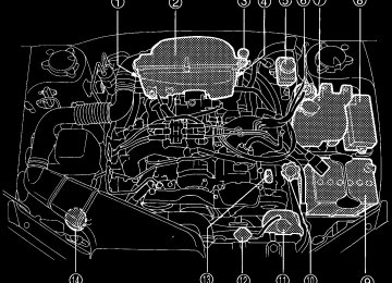
3.0 liter models: PLFR6A-11 (NGK)
11
– CONTINUED –
11-21
Legacy U.S.A..(ENG.)A2290BE–A
Drive belts
The alternator, power steering pump, and air conditioner compressor de- pend on drive belts. Satisfactory performance requires that belt tension be correct.
B 2.5 liter models
HGA005BB
Deflection
in (mm)
New belt
0.28 — 0.35
(7.0 — 9.0)0.30 — 0.33
(7.5 — 8.5)Used belt
0.35 — 0.43
(9.0 — 11.0)0.35 — 0.40
(9.0 — 10.0)To check belt tension, place a straightedge (ruler) across two adja- cent pulleys and apply a force of 22 lb (98 N, 10 kg) midway between the pulleys by using a spring scale. Belt deflection should be the amount specified.
B 3.0 liter models It is unnecessary to check belt tension periodically because your engine is equipped with an automatic belt tension adjuster. However, replacement of the belt should be done according to the maintenance
11-22
Legacy U.S.A..(ENG.)A2290BE–A
Maintenance and service
schedule in the “Warranty and Maintenance Booklet”. Consult your SUBARU dealer for replacement. If a belt is loose, cracked, or worn, contact your SUBARU dealer.
Manual transmission oil
B Checking the oil level Check the oil level monthly. 1. Park the vehicle on a level surface and stop the engine.
Upper level
Lower level
HBB004DB
OM-H0210
2. Pull out the dipstick, wipe it clean, and insert it again. 3. Pull out the dipstick again and check the oil level on it. If it is below the lower level, add oil through the dipstick hole to bring the level up to the upper level.
B Recommended grade and viscosity Each oil manufacturer has its own base oils and additives. Never use different brands together.
11
Oil grade: API classification GL-5
– CONTINUED –
11-23
Legacy U.S.A..(ENG.)A2290BE–A
SAE viscosity No. and Applicable Temperature
OM-H0205
Automatic transmission fluid
B Checking the fluid level The automatic transmission fluid expands largely as its temperature rises; the fluid level differs according to fluid temperature. Therefore, there are two different scales for checking the level of hot fluid and cold fluid on the dipstick.
Though the fluid level can be checked without warming up the fluid on the “COLD” range, we recommend checking the fluid level when the fluid is at operating temperature.
n Checking the fluid level when the fluid is hot Check the fluid level monthly. 1. Drive the vehicle several miles to raise the temperature of the transmission fluid up to normal operating temperature; 140 to 176°F (60 to 80°C) is normal. 2. Park the vehicle on a level surface and set the parking brake. 3. First shift the selector lever in each position. Then shift it in the “P” position, and run the engine at idling speed.
11-24
Legacy U.S.A..(ENG.)A2290BE–A
Maintenance and service
Upper level
Lower level
COLD range
HOT range
Upper level
Lower level
HBB004CB
HBA008BB
4. Pull out the dipstick and check the fluid level on the gauge. If it is below the lower level on the “HOT” range, add the recommended au- tomatic transmission fluid up to the upper level.
n Checking the fluid level when the fluid is cold When the fluid level has to be checked without time to warm up the automatic transmission, check to see that the fluid level is between the lower level and upper level on the “COLD” range. If it is below that range, add fluid up to the upper level. Be careful not to overfill.
B Recommended fluid
“Dexron III” Type Automatic Transmission Fluid
11
– CONTINUED –
11-25
Legacy U.S.A..(ENG.)A2290BE–A
Front differential gear oil (AT vehicles)
B Checking the oil level Check the differential oil level monthly.
HBB004EB
Upper level
Lower level
HBA010BB
1. Park the vehicle on a level surface and stop the engine. 2. Pull out the dipstick, wipe it clean, and insert it again. 3. Pull out the dipstick again and check the oil level on it. If it is below the lower level, add oil to bring the level up to the upper level.
B Recommended grade and viscosity Each oil manufacturer has its own base oils and additives. Never use different brands together.
Oil grade: API classification GL-5
11-26
Legacy U.S.A..(ENG.)A2290BE–A
SAE viscosity No. and Applicable Temperature
Maintenance and service
OM-H0212
Rear differential gear oil
B Checking the gear oil level
CAUTION
If the vehicle requires frequent refilling, there may be an oil leak. If you suspect a problem, have the vehicle checked at your SUBARU dealer.
Your vehicle may be equipped with a rear differential protector. The differential protector provides protection to the rear differential assem- bly during off-road use. Removal of the rear differential protector is not required when checking the oil level.
11
– CONTINUED –
11-27
Legacy U.S.A..(ENG.)A2290BE–A
HBB065BB
HBB066BB
Others
Filler plug
Oil level
Filler hole
Drain hole
HB0078
Drain plug
HB0077
Remove the plug from the filler hole and check the oil level. The oil level should be kept even with the bottom of the filler hole. If the oil level is below the bottom edge of the hole, add oil through the filler hole to raise the level.
B Recommended grade and viscosity Each oil manufacturer has its own base oils and additives. Never use different brands together.
Oil grade: API classification GL-5
11-28
Legacy U.S.A..(ENG.)A2290BE–A
SAE viscosity No. and Applicable Temperature
Maintenance and service
OM-H0205
Power steering fluid
B Checking the fluid level
WARNING
Be careful not to burn yourself because the fluid may be hot.
CAUTION
D When power steering fluid is being added, use only clean fluid, and be careful not to allow any dirt into the tank. And never use different brands together. D Avoid spilling fluid when adding it in the tank.
The power steering fluid expands greatly as its temperature rises; the fluid level differs according to fluid temperature. Therefore, the reser- voir tank has two different checking ranges for hot and cold fluids.
Check the power steering fluid level monthly. 1. Park the vehicle on a level surface, and stop the engine. 2. Check the fluid level of the reservoir tank. When the fluid is hot after the vehicle has been run: Check that the oil level is between “HOT MIN” and “HOT MAX” on the surface of the reservoir tank.
– CONTINUED –
11-29
11
Legacy U.S.A..(ENG.)A2290BE–A
When the fluid is cool before the vehicle is run: Check that the oil level is between “COLD MIN” and “COLD MAX” on the surface of the res- ervoir tank. 3. If the fluid level is lower than the applicable “MIN” line, add the recommended fluid as necessary to bring the level between the “MIN” and “MAX” line.
Reservoir tank
Specified range
Specified range
HBB030BB
HBB031BB
If the fluid level is extreme low, it may indicate possible leakage. Con- sult your SUBARU dealer for inspection.
B Recommended fluid
“Dexron III” Type Automatic Transmission Fluid
Brake fluid
B Checking the fluid level
WARNING
D Never let brake fluid contact your eyes because brake fluid can be harmful to your eyes. If brake fluid gets in your eyes, immedi- ately flush them thoroughly with clean water. For safety, when performing this work, wearing eye protection is advisable. D Brake fluid absorbs moisture from the air. Any absorbed mois- ture can cause a dangerous loss of braking performance.
11-30
Legacy U.S.A..(ENG.)A2290BE–A
Maintenance and service
D If the vehicle requires frequent refilling, there may be a leak. If you suspect a problem, have the vehicle checked at your SUBARU dealer.
CAUTION
D Never use different brands of brake fluid together. D When adding brake fluid, be careful not to allow any dirt into the reservoir. D Never splash the brake fluid over painted surfaces or rubber parts. Alcohol contained in the brake fluid may damage them.
Check the fluid level monthly.
“MAX” level mark
“MIN” level mark
HBB004GB
Check the fluid level on the outside of the reservoir. If the level is be- low “MIN”, add the recommended brake fluid to “MAX”. Use only brake fluid from a sealed container.
11
B Recommended brake fluid
FMVSS No. 116, fresh DOT 3 or 4 brake fluid
– CONTINUED –
11-31
Legacy U.S.A..(ENG.)A2290BE–A
Clutch fluid (MT vehicles)
B Checking the fluid level
WARNING
Never let clutch fluid contact your eyes because clutch fluid can be harmful to your eyes. If clutch fluid gets in your eyes, immedi- ately flush them thoroughly with clean water. For safety, when performing this work, wearing eye protection is advisable.
CAUTION
D Clutch fluid absorbs moisture from the air. Any absorbed moisture can cause improper clutch operation. D If the vehicle requires frequent refilling, there may be a leak. If you suspect a problem, have the vehicle checked at your SUBARU dealer. D Never use different brands of clutch fluid together. D When clutch fluid is added, be careful not to allow any dirt into the tank.
Check the fluid level on the outside of the reservoir. If the level is below “MIN” level mark, add the recommended clutch fluid to “MAX” level mark. Use only clutch fluid from a sealed container.
“MAX” level mark
“MIN” level mark
11-32
HBB004HB
Legacy U.S.A..(ENG.)A2290BE–A
Maintenance and service
B Recommended clutch fluid
FMVSS No. 116, fresh DOT 3 or 4 brake fluid
Brake booster
If the brake booster does not operate as described below, have it checked by your SUBARU dealer. 1. With the engine off, depress the brake pedal several times, applying the same pedal force each time. The distance the pedal travels should not vary. 2. With the brake pedal depressed, start the engine. The pedal should move slightly down to the floor. 3. With the brake pedal depressed, stop the engine and keep the pedal depressed for 30 seconds. The pedal height should not change. 4. Start the engine again and run for about one minute then turn it off. Depress the brake pedal several times to check the brake booster. Brake booster operates properly if the pedal stroke decreases with each depression.
11
– CONTINUED –
11-33
Legacy U.S.A..(ENG.)A2290BE–A
Brake pedal
Check the brake pedal free play and reserve distance according to the maintenance schedule in the “Warranty and Maintenance Booklet”.
B Checking the brake pedal free play
0.04 — 0.12 in (1.0 — 3.0 mm)
OM-H0224
Stop the engine and firmly depress the brake pedal several times. Lightly press the brake pedal down with one finger to check the free play with a force of less than 2 lb (10 N, 1 kg). If the free play is not within proper specification, contact your SUBARU dealer.
B Checking the brake pedal reserve distance
More than 2.56 in (65 mm)
Depress the pedal with a force of approximately 66 lb (294 N, 30 kg)
OM-H0225
11-34
Legacy U.S.A..(ENG.)A2290BE–A
Maintenance and service
and measure the distance between the upper surface of the pedal pad and the floor. When the measurement is smaller than the specification, or when the pedal does not operate smoothly, contact with your SUBARU dealer.
Clutch pedal (Manual transmission vehicles)
Check the clutch pedal free play and reserve distance according to the maintenance schedule in the “Warranty and Maintenance Booklet”.
B Checking the clutch function Check the clutch engagement and disengagement. 1. With the engine idling, check that there are no abnormal noises when the clutch pedal is depressed, and that shifting into 1st or re- verse feels smooth. 2. Start the vehicle by releasing the pedal slowly to check that the en- gine and transmission smoothly couple without any sign of slippage.
B Checking the clutch pedal free play
0.16 — 0.51 in (4.0 — 13.0 mm)
OM-H0224
11
Lightly press the clutch pedal down with your finger until you feel re- sistance, and check the free play. If the free play is not within proper specification, contact your SUBARU dealer.
– CONTINUED –
11-35
Legacy U.S.A..(ENG.)A2290BE–A
Replacement of brake pad and lining
CAUTION
If you continue to drive despite the scraping noise from the audi- ble brake pad wear indicator, it will result in the need for costly brake rotor repair or replacement.
OM-H0163
The front disc brakes and the right rear disc brake have an audible wear indicators on the brake pads. If the brake pads wear close to their ser- vice limit, the wear indicator makes a very audible scraping noise when the brake pedal is applied.
If you hear this scraping noise each time you apply the brake pedal, have the brake pads serviced by your SUBARU dealer as soon as pos- sible.
B Breaking-in of new brake pads and linings When replacing the brake pad or lining, use only genuine SUBARU parts. After replacement, the new parts must be broken in as follows:
n Brake pad and lining While maintaining a speed of 30 to 40 mph (50 to 65 km/h), step on the brake pedal lightly. Repeat this five or more times.
11-36
Legacy U.S.A..(ENG.)A2290BE–A
Maintenance and service
n Parking brake lining
WARNING
A safe location and situation should be selected for break-in driv- ing.
CAUTION
Pulling the parking brake lever too forcefully may cause the rear wheels to lock. To avoid this, be certain to pull the lever up slowly and gently.
1. Drive the vehicle at a speed of about 22 mph (35 km/h). 2. With the parking brake release button pushed in, pull the parking brake lever SLOWLY and GENTLY. (Pulling with a force of approxi- mately 33 lb [147 N, 15 kg].) 3. Drive the vehicle for about 220 yards (200 meters) in this condition. 4. Wait 5 to 10 minutes for the parking brake to cool down. Repeat this procedure. 5. Check the parking brake stroke. If the parking brake stroke is out of the specified range, adjust it by turning the adjusting nut located on the parking brake lever.
Parking brake stroke: 7 — 8 notches / 44 lb (196 N, 20 kg)
Parking brake stroke
11
Check the parking brake stroke according to the maintenance schedule in the “Warranty and Maintenance Booklet”. When the parking brake is properly adjusted, braking power is fully applied by pulling the lever up seven to eight notches gently but firmly (about 44 lb, 196 N, 20 kg). If the parking brake lever stroke is not within the specified range, have the brake system checked and adjusted at your SUBARU dealer.
– CONTINUED –
11-37
Legacy U.S.A..(ENG.)A2290BE–A
HB4001CB
Tires and wheels
J Types of tires You should be familiar with type of tires present on your vehicle.
B All season tires The factory-installed tires on your new vehicle are all season tires. All season tires are designed to provide an adequate measure of trac- tion, handling and braking performance in year-round driving includ- ing snowy and icy road conditions. However all season tires do not offer as much traction performance as winter (snow) tires in heavy or loose snow or on icy roads. All season tires are identified by “ALL SEASON” and/or “M+S” (Mud & Snow) on the tire sidewall.
B Summer tires Summer tires are high-speed capability tires best suited for highway driving under dry conditions. Summer tires are inadequate for driving on slippery roads such as on snow-covered or icy roads. If you drive your vehicle on snow-covered or icy roads, we strongly recommend the use of winter (snow) tires. When installing winter tires, be sure to replace all four tires.
11-38
Legacy U.S.A..(ENG.)A2290BE–A
Maintenance and service
B Winter (snow) tires Winter tires are best suited for driving on snow-covered and icy roads. However winter tires do not perform as well as summer tires and all season tires on roads other than snow-covered and icy roads.
J Tire inspection Check on a daily basis that the tires are free from serious damage, nails, and stones. At the same time, check the tires for abnormal wear. Contact your SUBARU dealer immediately if you find any problem.
NOTE D When the wheels and tires strike curbs or are subjected to harsh treatment as when the vehicle is driven on a rough surface, they can suffer damage that cannot be seen with the naked eye. This type of damage does not become evident until time has passed. Try not to drive over curbs, potholes or on other rough surfaces. If doing so is unavoidable, keep the vehicle’s speed down to a walking pace or less, and approach the curbs as squarely as possible. Also, make sure the tires are not pressed against the curb when you park the vehicle. D If you feel unusual vibration while driving or find it difficult to steer the vehicle in a straight line, one of the tires and/or wheels may be damaged. Drive slowly to the nearest authorized SUBARU dealer and have the vehicle inspected.
J Tire pressures and wear Maintaining the correct tire pressures helps to maximize the tires’ service lives and is essential for good running performance. Check and, if nec- essary, adjust the pressure of each tire (including the spare) at least once a month (for example, during a fuel stop) and before any long jour- ney.
Check the tire pressures when the tires are cold. Use a pressure gauge to adjust the tire pressures to the values shown on the tire placard. The tire placard is located on the door pillar on the driver’s side.
– CONTINUED –
11-39
11
Legacy U.S.A..(ENG.)A2290BE–A
HB0382
Driving even a short distance warms up the tires and increases the tire pressures. Also, the tire pressures are affected by the ambient tempera- ture. It is best to check tire pressure outdoors before driving the vehicle.
When a tire becomes warm, the air inside it expands, causing the tire pressure to increase. Be careful not to mistakenly release air from a warm tire to reduce its pressure.
NOTE D The air pressure in a tire increases by approximately 4.3 psi (30
kPa, 0.3 kg/cm2) when the tire becomes warm. D The tires are considered cold when the vehicle has been parked for at least three hours or has been driven less than one mile (1.6
km).WARNING
Do not let air out of warm tires to adjust pressure. Doing so will result in low tire pressure.
Incorrect tire pressures detract from controllability and ride comfort, and they cause the tires to wear abnormally.
11-40
Legacy U.S.A..(ENG.)A2290BE–A
D Correct tire pressure (tread worn evenly)
Maintenance and service
HGB033AA
Roadholding is good, and steering is responsive. Rolling resistance is low, so fuel consumption is also lower.
D Abnormally low tire pressure (tread worn at shoulders)
HSB012AA
11
Rolling resistance is high, so fuel consumption is also higher.
– CONTINUED –
11-41
Legacy U.S.A..(ENG.)A2290BE–A
D Abnormally high tire pressure (tread worn in center)
HSB013AA
Ride comfort is poor. Also, the tire magnifies the effects of road-sur- face bumps and dips, possibly resulting in vehicle damage.
If the tire placard shows tire pressures for the vehicle when fully loaded and for the vehicle when towing a trailer, adjust the tire pressures to the values that match current loading conditions.
WARNING
Driving at high speeds with excessively low tire pressures can cause the tires to deform severely and to rapidly become hot. A sharp increase in temperature could cause tread separation, and destruction of the tires. The resulting loss of vehicle control could lead to an accident.
J Wheel balance Each wheel was correctly balanced when your vehicle was new, but the wheels will become unbalanced as the tires become worn during use. Wheel imbalance causes the steering wheel to vibrate slightly at certain vehicle speeds and detracts from the vehicle’s straight-line stability. It can also cause steering and suspension system problems and abnormal tire wear. If you suspect that the wheels are not correctly balanced, have them checked and adjusted by your SUBARU dealer. Also have them adjusted after tire repairs and after tire rotation.
11-42
Legacy U.S.A..(ENG.)A2290BE–A
Maintenance and service
NOTE Loss of correct wheel alignment* causes the tires to wear on one side and reduces the vehicle’s running stability. Contact your SUBARU dealer if you notice abnormal tire wear.
* : The suspension system is designed to hold each wheel at a certain alignment (relative to the other wheels and to the road) for optimum straight-line stability and cornering performance.
J Wear indicators Each tire incorporates a tread wear indicator, which becomes visible when the depth of the tread grooves decreases to 0.063 in. (1.6 mm). A tire must be replaced when the tread wear indicator appears as a solid band across the tread.
A) New tread B) Worn tread 1) Tread wear indicator
OM-H0231
11
WARNING
When a tire’s tread wear indicator becomes visible, the tire is worn beyond the acceptable limit and must be replaced immedi- ately. With a tire in this condition, driving at high speeds in wet weather can cause the vehicle to hydroplane. The resulting loss of vehicle control can lead to an accident.
NOTE For safety, inspect the tire tread regularly and replace the tires be- fore their tread wear indicators become visible.
– CONTINUED –
11-43
Legacy U.S.A..(ENG.)A2290BE–A
J Tire rotation
OM-H0230
Tire wear varies from wheel to wheel. To maximize the life of each tire and ensure that the tires wear uniformly, it is best to rotate the tires every 7,500 miles (12,500 km). Rotating the tires involves switching the front and rear tires on the right-hand side of the vehicle and similarly switching the front and rear tires on the left-hand side of the vehicle. (Each tire must be kept on its original side of the vehicle.) Replace any damaged or unevenly worn tire at the time of rotation. After tire rotation, adjust the tire pressures and make sure the wheel nuts are correctly tightened. After driving approximately 600 miles (1,000 km), check the wheel nuts again and retighten any nut that has become loose.
J Tire replacement The wheels and tires are important and integral parts of your vehicle’s design; they cannot be changed arbitrarily. The tires fitted as standard equipment are optimally matched to the characteristics of the vehicle and were selected to give the best possible combination of running per- formance, ride comfort, and service life. It is essential for every tire to have a size and construction matching those shown on the tire placard and to have a speed symbol and load index matching those shown on the tire placard. Using tires of a non-specified size detracts from controllability, ride com- fort, braking performance, speedometer accuracy and odometer accu-
11-44
Legacy U.S.A..(ENG.)A2290BE–A
Maintenance and service
racy. It also creates incorrect body-to-tire clearances and inappropriately changes the vehicle’s ground clearance.
All four tires must be the same in terms of manufacturer, brand (tread pattern), construction, and size. You are advised to replace the tires with new ones that are identical to those fitted as standard equipment.
For safe vehicle operation, SUBARU recommends replacing all four tires at the same time.
WARNING
D All four tires must be the same in terms of manufacturer, brand (tread pattern), construction, degree of wear, speed symbol, load index and size. Mixing tires of different types, sizes or degrees of wear can result in damage to the vehicle’s power train. Use of dif- ferent types or sizes of tires can also dangerously reduce con- trollability and braking performance and can lead to an accident. D Use only radial tires. Do not use radial tires together with belted bias tires and/or bias-ply tires. Doing so can dangerously reduce controllability, resulting in an accident.
J Wheel replacement When replacing wheels due, for example, to damage, make sure the re- placement wheels match the specifications of the wheels that are fitted as standard equipment. Replacement wheels are available from SUBARU dealers.
WARNING
Use only those wheels that are specified for your vehicle. Wheels not meeting specifications could interfere with brake caliper op- eration and may cause the tires to rub against the wheel well housing during turns. The resulting loss of vehicle control could lead to an accident.
– CONTINUED –
11-45
11
Legacy U.S.A..(ENG.)A2290BE–A
J Wheel covers
B Removing the wheel cover
HB9032BA
Insert the wheel nut wrench into the notch provided, and pry the wheel cover off.
B Installing the wheel cover
HGA013BA
Align the valve with the valve hole in the cover, then fit the cover on the wheel by tapping your hand evenly around the circumference of the cover.
NOTE When any of the wheels is removed and replaced for tire rotation or to change a flat tire, always check the tightness of the wheel nuts af- ter driving approximately 600 miles (1,000 km). If any nut is loose,
11-46
Legacy U.S.A..(ENG.)A2290BE–A
Maintenance and service
tighten it to the specified torque.
Aluminum wheels (If equipped)
Aluminum wheels can be scratched and damaged easily. Handle them carefully to maintain their appearance, performance, and safety.
D When any of the wheels is removed and replaced for tire rotation or to change a flat, always check the tightness of the wheel nuts after driving approximatly 600 miles (1,000 km). If any nut is loose, tighten it to the specified torque. D Never apply oil to the threaded parts, wheel nuts, or tapered surface of the wheel. D Never let the wheel rub against sharp protrusions or curbs. D Be sure to fit tire chains on uniformly and completely around the tire, otherwise the chains may scratch the wheel. D When wheel nuts, balance weights, or the center cap is replaced, be sure to replace them with genuine SUBARU parts designed for aluminum wheels.
Windshield washer fluid
CAUTION
Never use engine coolant as washer fluid because it could cause paint damage.
Check the level of the washer fluid at each fuel stop. If the level is low, fill the fluid up to the neck of the reservoir. Use windshield washer fluid. If windshield washer fluid is unavailable use clean water. In areas where water freezes in winter, use an anti-freeze type windshield washer fluid. SUBARU Windshield Washer Fluid contains 58.5% methyl alcohol and 41.5% surfactant, by volume. Its freezing temperature varies according to how much it is diluted, as indicated below.
– CONTINUED –
11-47
11
Legacy U.S.A..(ENG.)A2290BE–A
Washer Fluid Concentration
Freezing Temperature
30% 50% 100%
10.4°F (–12°C) –4 °F (–20°C) –49°F (–45°C)
HBB004IA
Replacement of windshield wiper blades
Grease, wax, insects, or other materials on the windshield or the wiper blade results in jerky wiper operation and streaking on the glass. If you cannot remove the streaks after operating the windshield washer or if the wiper operation is jerky, clean the outer surface of the windshield (or rear window) and the wiper blades using a sponge or soft cloth with a neutral detergent or mild-abrasive cleaner. After cleaning, rinse the windshield and wiper blades with clean water. The windshield is clean if beads do not form when you rinse the windshield with water.
CAUTION
Do not clean the wiper blades with gasoline or a solvent, such as paint thinner or benzene. This will cause deterioration of the wiper blades.
If you cannot eliminate the streaking even after following this method, replace the wiper blades using the following procedures:
11-48
Legacy U.S.A..(ENG.)A2290BE–A
Maintenance and service
1. Raise the wiper arm off the windshield. 2. Remove the wiper blade assembly by holding its pivot area and push- ing it in the direction shown by the arrow while depressing the wiper blade stopper.
Stopper
HS0190
3. Grasp the locked end of the blade rubber assembly and pull it firmly until the stoppers on the rubber are free of the metal support.
Metal support
HS0191
11
– CONTINUED –
11-49
Legacy U.S.A..(ENG.)A2290BE–A
4. If the new blade rubber is not provided with two metal spines, remove the metal spines from the old blade rubber and install them in the new blade rubber.
Metal spines
HS0192
5. Align the claws of the metal support with the grooves in the rubber and slide the blade rubber assembly into the metal support until it locks. Be sure to position the claws at the end of the metal support between the stoppers on the rubber as shown. If the rubber is not retained properly, the wiper blade may scratch the windshield.
Stopper
HS0193
HS0194
6. Install the wiper blade assembly to the wiper arm. Make sure that it locks in place. 7. Lower the wiper arm.
11-50
Legacy U.S.A..(ENG.)A2290BE–A
Battery
Maintenance and service
WARNING
D Before beginning work on or near any battery, be sure to extin- guish all cigarettes, matches, and lighters. Never expose a bat- tery to an open flame or electric sparks. Batteries give off a gas which is highly flammable and explosive. D For safety, in case an explosion does occur, wear eye protec- tion or shield your eyes when working near any battery. Never lean over a battery. D Do not let battery fluid contact eyes, skin, fabrics, or paint be- cause battery fluid is a corrosive acid. If battery fluid gets on your skin or in your eyes, immediately flush the area with water thor- oughly. Seek medical help immediately if acid has entered the eyes. If battery fluid is accidentally swallowed, immediately drink a large amount of milk or water, and seek medical attention immediately. D To lessen the risk of sparks, remove rings, metal watchbands, and other metal jewelry. Never allow metal tools to contact the positive battery terminal and anything connected to it WHILE you are at the same time in contact with any other metallic portion of the vehicle because a short circuit will result. D Keep everyone including children away from the battery. D Charge the battery in a well-ventilated area. D Battery posts terminals and related accessories contain lead and lead compounds, chemicals known to the State of California to case cancer and reproductive harm. Wash hands after han- dling.
CAUTION
Never use more than 10 amperes when charging the battery be- cause it will shorten battery life.
– CONTINUED –
11-51
11
Legacy U.S.A..(ENG.)A2290BE–A
It is unnecessary to periodically check the battery fluid level or periodi- cally refill with distilled water.
Fuses
CAUTION
Never replace a fuse with one having a higher rating or with mate- rial other than a fuse because serious damage or a fire could re- sult.
HBB008DA
HB8003CA
The fuses are designed to melt during an overload to prevent damage to the wiring harness and electrical equipment. The fuses are located in two fuse boxes. One is located under the instrument panel behind the coin tray on the driver’s seat side. The other one is housed in the engine compartment. The fuse puller and spare fuses are stored in the main fuse box cover in the engine compartment. If any lights, accessories or other electrical controls do not operate, in- spect the corresponding fuse. If a fuse has blown, replace it.
11-52
Legacy U.S.A..(ENG.)A2290BE–A
Good
Blown
Maintenance and service
HS0204
HSB011BB
1. Turn the ignition switch to the “LOCK” position and turn off all electri- cal accessories. 2. Remove the cover. (For behind the coin tray: open the coin tray and pull it horizontally to remove it.) 3. Determine which fuse may be blown. The back side of each fuse box cover and the “Fuse and circuits” section in chapter 12 in this manual show the circuit for each fuse.
Fuse puller
11
HS0207
4. Pull out the fuse with the fuse puller. 5. Inspect the fuse. If it has blown, replace it with a spare fuse of the same rating. 6. If the same fuse blows again, this indicates that its system has a problem. Contact your SUBARU dealer for repairs.
– CONTINUED –
11-53
Legacy U.S.A..(ENG.)A2290BE–A
Main fuse
HB8003CB
The main fuses are designed to melt during an overload to prevent dam- age to the wiring harness and electrical equipment. Check the main fuses if any electrical component fails to operate (except the starter mo- tor) and other fuses are good. A melted main fuse must be replaced. Use only replacements with the same specified rating as the melted main fuse. If a main fuse blows after it is replaced, have the electrical system checked by your nearest SUBARU dealer.
Installation of accessories
Always consult your SUBARU dealer before installing fog lights or any other electrical equipment in your vehicle. Such accessories may cause the electronic system to malfunction if they are incorrectly installed or if they are not suited for the vehicle.
11-54
Legacy U.S.A..(ENG.)A2290BE–A
Replacing bulbs
Maintenance and service
1 Headlight
GT and OUTBACK models
Low beam High beam
Except GT and OUTBACK models
2 Front turn signal 3 Spot light 4 Dome light 5 Door step light 6 Front turn signal light/
HB5019EB
Wattage
Bulb No.
H1
12V–55W 12V–60W 9005 (HB3) 12V–65/55W 9007 (HB5) 12V–27W 12V–8W 12V–8W 12V–3.4W1156NA (Amber) — — —
11
parking and front side marker light
12V–27/8W
1157NA (Amber)
7 Front fog light
Except OUTBACK OUTBACK
12V–55W 12V–51W
H3
9006 (HB4)– CONTINUED –
11-55
Legacy U.S.A..(ENG.)A2290BE–A
HBF013FC
8 Backup light
Sedan Station wagon
9 Luggage area light Q High mount stop light
Sedan Station wagon
W Rear turn signal light
Sedan Station wagon
E Brake/tail light
Sedan Station wagon R Licence plate light
Sedan Station wagon T Trunk room light
11-56
HBB033BC
Wattage
Bulb No.
12V–27W 12V–27W 12V–13W
12V–16W 12V–13W
12V–21W 12V–21W
12V–27/8W 12V–27/8W
3156K 1156
912921
912— 7440
3157K 1157
12V–5W 12V–3.8W or 5W 194 or 168
12V–5WW5W
168
Legacy U.S.A..(ENG.)A2290BE–A
Maintenance and service
J Headlight
CAUTION
Halogen headlight bulbs become very hot while in use. If you touch the bulb surface with bare hands or greasy gloves, finger prints or grease on the bulb surface develop into hot spots, caus- ing the bulb to break. If there are finger prints or grease on the bulb surface, wipe them away with a soft cloth moistened with al- cohol.
NOTE If headlight aiming is required, consult your SUBARU dealer for proper adjustment of the headlight aim.
B For GT and OUTBACK models
Remove the headlight bulb cover, by turning it counterclockwise.
HBB039BA
HBB040BB
11
– CONTINUED –
11-57
Legacy U.S.A..(ENG.)A2290BE–A
n Low beam light bulbs
HBB041BB
HBB042BA
1. Disconnect the electrical connector for the black cable. 2. Remove the retainer spring. 3. Replace the bulb, then set the retainer spring securely. 4. Reconnect the electrical connector for black cable. 5. Install the headlight bulb cover.
n High beam light bulbs
HBB043BA
HBB044BB
1. Disconnect the electrical connector from the bulb. 2. Remove the bulb from the headlight assembly by turning it coun- terclockwise. 3. Replace the bulb with new one. 4. Reconnect the electrical connector. At this time, use care not to touch the bulb surface.
11-58
Legacy U.S.A..(ENG.)A2290BE–A
Maintenance and service
5. To install the bulb to the headlight assembly, turn it clockwise until it clicks. 6. Install the headlight bulb cover. B Except GT and OUTBACK models
HBB045BB
HBB046BA
1. Disconnect the electrical connector while pressing the lock release tab. 2. Remove the bulb holder from the headlight assembly by turning it counterclockwise. 3. Remove the bulb from the headlight assembly. 4. Install the new bulb. 5. Install the bulb holder in the headlight assembly by turning it clock- wise until it locks. 6. Remove the electrical connector.
J Front fog light (if equipped) It may be difficult to replace the bulbs. Have your SUBARU dealer replace the bulbs if necessary.
11
J Front turn signal light, parking light and side marker
light
The headlight assembly must be removed before the front turn signal light and parking light bulbs can be replaced. When the headlight as- sembly has been removed and then reinstalled, it may become neces- sary to make a headlight aiming adjustment. After a bulb has been re- placed, it is recommended that the headlight aiming adjustment be
– CONTINUED –
11-59
Legacy U.S.A..(ENG.)A2290BE–A
made at a SUBARU dealer.
HBB016BA
1. Remove the headlight assembly mounting screws located at the top of and the front of the headlight assembly using a phillips screwdriver or an open-end wrench. 2. Move the headlight assembly forward.
HBB039CB
HBB020BA
3. Remove the bulb socket from the headlight assembly by turning it counterclockwise. 4. Remove the bulb from the socket by pushing it and turning counter- clockwise. Install a new bulb in the socket. 5. Set the bulb socket into the headlight assembly and turn it clockwise until it locks. 6. Set the headlight assembly into the vehicle body. Tighten the mount- ing screws.
11-60
Legacy U.S.A..(ENG.)A2290BE–A
J Rear combination lights
B Sedan
Maintenance and service
HBF014DA
HBB034BC
HBB035BB
1. Open the trunk lid. 2. Open the rear combination light cover. For covers on the trunk lid: Unlatch the cover by pushing the knob and open the cover. For covers on the trunk wall: Unlatch the cover by moving the knob upward and open the cover. 3. Remove the bulb socket from the light assembly by turning it coun- terclockwise. 4. Remove the bulb from the socket. Rear turn signal light: Remove the bulb from the socket by pushing it and turning it counterclockwise. Others: Pull the bulb out of the socket.
– CONTINUED –
11-61
11
Legacy U.S.A..(ENG.)A2290BE–A
5. Install a new bulb in the socket. 6. Set the bulb socket into the rear combination light assembly and turn it clockwise until it locks. 7. Close the cover and latch the clock.
B Station wagon n Brake/tail and rear turn signal light bulbs It may be difficult to replace the bulbs. It is recommended that you have the bulbs replaced by your SUBARU dealer.
HBB021BB
HBB022BB
1. Remove the light bulb replacement service hole covers at two places by prying the edge of the cover with a regular screwdriver. 2. Remove the upper and lower nuts. Then, slide the rear combina- tion lamp assembly to the rear and remove it from the vehicle.
HBB070BB
11-62
Legacy U.S.A..(ENG.)A2290BE–A
Maintenance and service
3. Using a Phillips screwdriver, remove the upper and lower screws that secure the side cover of the rear combination light assembly. 4. Remove the bulb socket from the rear combination light assembly by turning it counterclockwise.
HBB048BB
HBB025BB
5. Remove the bulb from the socket. Turn signal light: Pull the bulb out of the socket. Brake/tail light: Remove the bulb from the socket by pushing it and turning it counterclockwise. 6. Install a new bulb in the socket. 7. Set the bulb holder into the rear combination light assembly and turn it clockwise until it locks. 8. Using a Phillips screwdriver, install the side cover to the rear com- bination light assembly. 9. Fit the rear combination light assembly into the vehicle body and tighten the nuts from the interior of the vehicle. 10. Reinstall the light bulb replacement service hole covers.
11
– CONTINUED –
11-63
Legacy U.S.A..(ENG.)A2290BE–A
n Back-up and brake/tail light bulbs
HBB026BC
HBB025BA
1. Unlatch the rear finisher light cover by moving the knob upward. Open the cover up. 2. Remove the bulb socket from the rear finisher light assembly by turning it counterclockwise. 3. Remove the bulb from the socket by pushing it and turning coun- terclockwise. Install a new bulb in the socket. 4. Set the bulb holder into the rear finisher light assembly and turn it clockwise until it locks. 5. Close the cover and latch the lock.
J License plate light
HBF013EA
HBB027BA
1. Remove the mounting screws using a phillips screwdriver.
11-64
Legacy U.S.A..(ENG.)A2290BE–A
Maintenance and service
2. Remove the cover and lens. 3. Pull the bulb out of the socket. Install a new bulb. 4. Reinstall the lens and cover. 5. Tighten the mounting screws.
J Spot light, dome light, luggage compartment light
and door step light
HBB029BB
HBB068BB
HSA005BB
HBB067BB
11
– CONTINUED –
11-65
Legacy U.S.A..(ENG.)A2290BE–A
HBS037AB
1. Remove the lens by prying the edge of the lens with a regular screw- driver. 2. Pull the bulb out of the socket. Install a new bulb. 3. Reinstall the lens.
J Trunk light
HBF014FA
1. Remove the cover by squeezing its sides and pulling it. 2. Pull the bulb out of the socket. Install a new bulb. 3. Reinstall the cover.
11-66
Legacy U.S.A..(ENG.)A2290BE–A
J High mount stop light
B Sedan
Maintenance and service
OM-H2350
1. Remove the high mount stop light cover by prying on the edge with a screwdriver. 2. Pull the bulb out of the socket. Install a new bulb. 3. Reinstall the cover.
B Station wagon
11
HBB028BA
1. Remove the mounting screw covers by prying on the edge with a screwdriver. 2. Remove the mounting screws using a phillips screwdriver and then remove the high mount stop light cover. 3. Pull the bulb out of the socket. Install a new bulb.
– CONTINUED –
11-67
Legacy U.S.A..(ENG.)A2290BE–A
4. Reinstall the cover. 5. Tighten the mounting screws then reinstall the covers.
NOTE Other bulbs may be difficult to replace. Have your SUBARU dealer replace these bulbs if necessary.
11-68
Legacy U.S.A..(ENG.)A2290BE–A
Specifications
Specifications Dimensions Engine Electrical system Capacities Tires Wheel alignment Fuses and circuits
. . . . . . . . . . . . . . . . . . . . . . . . . . . . . . . . . . . . . . . . . . . . . . . . . . . . . . . . . . . . . . . . . . . . . . . . . . . . . . . . . . . . . . . . . . . . . . . . . . . . . . . . . . . . . . . . . . . . . . . . . . . . . . . . . . . . . . . . . . . . . . . . . . . . . . . . . . . . . . . . . . . . . . . . . . . . . . . . . . . . . . . . . . . . . . . . . . . . . . . . . . . . . . . . . . . . . . . . . . . . . . . . . . . . . . . . . . . . . . . . . . . . . . . . . . . . . . . . . . . . . . . . . . . . . . . . . . . . . . . . . . . . . . . . . . . . . . . . . . . . . . . . . . . . . . . . . . . . . . . . . . . . . . . . . . . . . . . . . . . . . . . . . . . . . . . . . . . . . . . . . . . . . . . . . . . . . . . . . . . . . . . . . . . . . . . . . . . . . . . . . . . . . . . . . . . . . . . . . . . . . . . . . . . . . . . . . . . . . . . . . . . .
Fuse panel located behind the coin tray Fuse panel located in the engine compartment
. . . . . . . . . . . . . . . . . . . . . . . . . . . . . . . . . . . . . . . . . . . . . . . . . . . . . . . . . . . . . . . . . . . . . . . . . . . . . . . . . . . . . . . . . . . . . . . . . . . . . . .
Bulb chart Vehicle identification
. . . . . . . . . . . . . . . . . . . . . . . . . . . . . . . . . . . . . . . . . . . . . . . . . . . . . . . . . . . . . . . . . . .
. . . . . . . . . . . . . . . . . . . . . . . . . . . . . . . . . . . . . . . . . . . . . . . . . . . .
12-2
12-2
12-3
12-3
12-4
12-4
12-5
12-6
12-6
12-10
12-14
12-1512
Legacy U.S.A..(ENG.)A2290BE–A
Specifications
These specifications are subject to change without notice.
J Dimensions Legacy sedan Overall length Overall width Overall height Ground clearance Front tread Rear tread Wheelbase
Legacy station wagon Overall length Overall width Overall height
Ground clearance Front tread Rear tread Wheelbase
*: With roof rail
OUTBACK sedan Overall length Overall width Overall height Ground clearance Front tread Rear tread Wheelbase
OUTBACK station wagon Overall length Overall width
12-2
184.4 in (4,685 mm) 68.7 in (1,745 mm) 55.7 in (1,415 mm) 6.1 in (155 mm) 57.5 in (1,460 mm) 57.5 in (1,460 mm) 104.3 in (2,650 mm)
187.4 in (4,760 mm) 68.7 in (1,745 mm) 56.6 in (1,435 mm) 59.6 in (1,525 mm)* 6.3 in (160 mm) 57.5 in (1,460 mm) 57.3 in (1,455 mm) 104.3 in (2,650 mm)
184.4 in (4,685 mm) 68.7 in (1,745 mm) 58.3 in (1,480 mm) 7.3 in (185 mm) 57.9 in (1,470 mm) 57.7 in (1,465 mm) 104.3 in (2,650 mm)
187.4 in (4,760 mm) 68.7 in (1,745 mm)
Legacy U.S.A..(ENG.)A2290BE–A
Overall height Ground clearance
2.5 liter models 3.0 liter models
Front tread Rear tread Wheelbase
J Engine 2.5 liter Engine model Engine type
Engine displacement Bore Stroke Compression ratio Firing order
3.0 liter Engine model Engine type
Engine displacement Bore Stroke Compression ratio Firing order
Specifications
62.2 in (1,580 mm)
7.3 in (185 mm) 7.9 in (200 mm) 57.9 in (1,470 mm) 57.7 in (1,465 mm) 104.3 in (2,650 mm)
EJ251
Horizontally opposed, liquid cooled 4 cylinder, 4 stroke gasoline engine 2,457 cc (150 cu in.) 3.92 in (99.5 mm) 3.11 in (79.0 mm) 10.0 : 1
1 - 3 - 2 - 4EZ30D Horizontally opposed, liquid cooled 6 cylinder, 4 stroke gasoline engine 3,000 cc (183.0 cu in.) 3.51 in (89.2 mm) 3.15 in (80.0 mm) 10.7 : 1
1 - 6 - 3 - 2 - 5 - 4J Electrical system
2.5 liter Battery type and capacity
Alternator
MT: AT:
55D23L 75D23L 12V-90A
– CONTINUED –
12-3
12
Legacy U.S.A..(ENG.)A2290BE–A
Spark plugs type
RC10YC4 (Champion) BKR6E-11 (NGK) BKR5E-11 (NGK)
3.0 liter Battery type and capacity Alternator Spark plugs type
75D23L 12V-100A PLFR6A-11 (NGK)
J Capacities
Fuel tank Engine oil
2.5 liter 3.0 liter
Transmission oil (MT) Transmission fluid (AT) AT differential gear oil Rear differential gear oil
16.9 US gal (64 liters, 14.1 Imp gal) 4.2 US qt (4.0 liters, 3.5 Imp qt) 6.0 US qt (5.7 liters, 5.0 Imp qt) 3.7 US qt (3.5 liters, 3.1 Imp qt) 9.8 US qt (9.3 liters, 8.2 Imp qt) 1.3 US qt (1.2 liters, 1.1 Imp qt)
Power steering gear fluid Engine coolant
Brighton, L (AT) 0.9 US qt (0.9 liter, 0.8 Imp qt) Others 0.8 US qt (0.8 liter, 0.7 Imp qt) 0.7 US qt (0.7 liter, 0.6 Imp qt) 7.2 US qt (6.8 liters, 6.0 Imp qt) 7.1 US qt (6.7 liters, 5.9 Imp qt) 8.4 US qt (7.9 liters, 7.0 Imp qt)
2.5 liter MT AT
3.0 liter
J Tires Legacy Type
Size
Brighton GT
Temporary spare
Pressure Front
Rear
Brighton GT, L Brighton GT, L
12-4
Steel belted radial, Tubeless P195/60R15 87H P205/60R15 90H P205/55R16 89H T135/70D16
33 psi (230 kPa, 2.3 kg/cm2) 32 psi (220 kPa, 2.2 kg/cm2) 32 psi (220 kPa, 2.2 kg/cm2) 30 psi (210 kPa, 2.1 kg/cm2)
Legacy U.S.A..(ENG.)A2290BE–A
Temporary spare
Wheel size OUTBACK Type
Size
Temporary spare
Pressure Front
Rear
Trailer towing
Trailer towing
Temporary spare
Wheel size
J Wheel alignment
Legacy sedan Toe
Camber
Front Rear Front Rear
Legacy station wagon Toe
Camber
Front Rear Front Rear OUTBACK sedan Toe
Camber
Front Rear Front Rear
OUTBACK station wagon Front Toe Rear Front Rear
Camber
Specifications
60 psi (420 kPa, 4.2 kg/cm2) 15 x 6JJ, 16 x 61/2JJ
Steel belted radial, Tubeless P225/60R16 97H T145/80R16
30 psi (210 kPa, 2.1 kg/cm2) 30 psi (210 kPa, 2.1 kg/cm2) 29 psi (200 kPa, 2.0 kg/cm2) 32 psi (220 kPa, 2.2 kg/cm2) 60 psi (420 kPa, 4.2 kg/cm2) 16 x 61/2JJ
0 " 0.12 in (0 " 3 mm) 0 " 0.12 in (0 " 3 mm) –0°05’ " 30’ –0°30’ " 45’
0 " 0.12 in (0 " 3 mm) 0 " 0.12 in (0 " 3 mm) –0°05’ " 30’ –0°20’ " 45’
0 " 0.12 in (0 " 3 mm) 0 " 0.12 in (0 " 3 mm) 0°20’ " 30’ –0°10’ " 45’
0 " 0.12 in (0 " 3 mm) 0 " 0.12 in (0 " 3 mm) 0°20’ " 30’ –0°10’ " 45’
– CONTINUED –
12-5
12
Legacy U.S.A..(ENG.)A2290BE–A
Fuses and circuits
J Fuse panel located behind the coin tray
B 2.5 liter models
Fuse panel
Fuse rating Circuit
HBC001BB
15A
15A
15A
20A
10A
D Heater fan
D Heater fan
D Power door lock D Keyless entry
D Cigarette lighter D Remote controlled rear view mirrors
D Tail light D Parking light
12-6
Legacy U.S.A..(ENG.)A2290BE–A
Fuse panel
Fuse rating
Circuit
Specifications
10
11
12
13
14
15
16
17
18
19
20
15A
15A
30A
15A
15A
15A
10A
15A
10A
30A
20A
15A
15A
20A
20A
D SRS airbag
D Front fog light
D ABS solenoid
D Radio D Clock
D Trailer
D Engine ignition system D SRS airbag
D Illumination brightness control
D Fuel pump
D Rear window wiper and washer
D Windshield wiper and washer
D Brake light
D Air conditioner
D Backup light D Cruise control D ABS control
D Mirror heater D Wiper deicer
D Accessory power socket D Seat heater
– CONTINUED –
12-7
12
Legacy U.S.A..(ENG.)A2290BE–A
B 3.0 liter models
Fuse panel
Fuse rating Circuit
HBC001CB
15A
15A
15A
20A
10A
15A
15A
D Heater fan
D Heater fan
D Power door lock D Keyless entry
D Cigarette lighter D Remote controlled rear view mirrors
D Tail light D Parking light
D SRS airbag
D Front fog light
12-8
Legacy U.S.A..(ENG.)A2290BE–A
Fuse panel
Fuse rating
Circuit
Specifications
10
11
12
13
14
15
16
17
18
19
20
21
30A
15A
15A
15A
10A
15A
10A
30A
20A
15A
15A
20A
20A
20A
D ABS (VDC) solenoid
D Radio D Clock
D Trailer
D Engine ignition system D SRS airbag
D Illumination brightness control
D Fuel pump
D Rear window wiper and washer
D Windshield wiper and washer
D Brake light
D Air conditioner
D Backup light D Cruise control D ABS (VDC) control
D Mirror heater D Wiper deicer
D McIntosh audio amp (if equipped)
D Accessory power socket D Seat heater
12
– CONTINUED –
12-9
Legacy U.S.A..(ENG.)A2290BE–A
J Fuse panel located in the engine compartment
B 2.5 liter models
Fuse panel
Fuse rating Circuit
HBC003BB
20A
20A
50A
20A
15A
15A
10A
10A
15A
D Radiator cooling fan (Main)
D Radiator cooling fan (Sub)
D ABS motor
D Rear window defogger
D Hazard warning flasher D Horn
D Meter D SRS airbag system warning light
D Automatic transmission control unit D ABS UNIT
D Alternator
D Headlight (right side)
12-10
Legacy U.S.A..(ENG.)A2290BE–A
Specifications
Fuse panel
Fuse rating
Circuit
10
11
12
15A
20A
15A
D Headlight (left side)
D Lighting switch
D Clock D Interior light
12
– CONTINUED –
12-11
Legacy U.S.A..(ENG.)A2290BE–A
B 3.0 liter models
Fuse panel
Fuse rating Circuit
HBC004BC
30A
30A
50A
30A
20A
15A
15A
10A