- Download PDF Manual
-
To replace the single wiper blade, lift the arm away from the ‘screen, swing the blade through 90°, depress the retaining tab and slide the blade down the arm to unhook and release.
When refitting, ensure that the retaining clip is re-engaged
in the wiper arm slot.
oh_croft_InD.indd 109
20/05/2004 07:59:08
109
i
BRAKE FLUID RESERVOIR CAP
ohs139
Brake Fluid Reservoir
Under normal circumstances, there is no requirement for routine 'topping up' of the brake master cylinder reservoir. A visual safety check is all that is required.
Every week, check the level of fluid in the brake fluid reservoir located in the driver’s side of the front services compartment, beneath the access panel: Without disturbing the filler cap, check that the level lies between the 'MAX' and 'MIN' marks moulded on the translucent reservoir body. As the brake pads wear, the level will drop gradually from the 'MAX' mark towards the 'MIN', but if the level drops rapidly over a short period, have your Lotus dealer investigate without delay. If the level is found to be below the 'MIN’ mark, it is likely there has been some fluid loss, and that air will have entered the hydraulic system. The car should not be driven until the fault has been investigated and rectified. Note that a single reservoir is used to supply both of the independent hydraulic circuits for the front and rear brakes, and also serves the hydraulic clutch release circuit.
If any fluid is to be added, first clean the surrounding area to guard against dirt ingress before unscrewing the reservoir cap.
NOTICE: Spilled brake fluid can seriously damage the car’s paintwork and some plastic compoments, for example, the side marker lamps. Take suitable precautions to protect the paintwork from contamination, and in case of spillage, rinse the affected area with water immediately: DO NOT WIPE.
110
oh_croft_InD.indd 110
20/05/2004 07:59:08
i
Use only a non-mineral type DOT 4 brake fluid from a sealed container marked with a yellow and black (non-mineral) symbol. Do not use DOT 5 silicone fluid, or any fluid which has been exposed to the atmosphere for more than a brief period, or any fluid suspected of being wet, dirty or contaminated. Do not overfill, and replace the cap securely.
Brake fluid, being hygroscopic, absorbs water from the atmos- phere over a period of time, resulting in a lowering of the boiling point of the fluid, and corrosion of the hydraulic system. For optimum safety and brake performance, the brake fluid should be renewed every twelve months by your Lotus Dealer.
WARNING:
• Brake fluid is hazardous to health and may be fatal if
swallowed. Keep out of children’s reach.
• Using the wrong type of brake fluid can damage brake system components and result in brake failure causing a crash in which you and others could be killed or seriously injured. See ‘Recommended Lubricants’.
Brake Pads
The thickness of the brake pad lining material should be checked at every service, and under no circumstances be al- lowed to fall below 0.1 inch (2.5 mm). If the brakes are in very frequent or arduous use, as when driving in mountainous terrain, or on race circuits, it is recommended that they be examined more frequently. The pads should be renewed if of insufficient thickness to ensure safe braking until the next scheduled service.
Note that in order to ensure that brake pads with the correct material specification are used, only genuine Lotus replacement parts should be fitted, and in the interests of safety, pad renewal should be entrusted to your Lotus dealer.
WARNING: Using incorrect brake pads, or pads below 0.1 inch (2.5mm) thickness, may cause a crash in which you or others could be killed or seriously injured.
With a new car, or new brake system components, maxi- mum braking efficiency will be achieved if, for the first few hundred miles, needless heavy braking is avoided, and the brake pads and discs are allowed to ‘bed in’ fully before being used to their full potential (see also ‘Footbrake’).
111
oh_croft_InD.indd 111
20/05/2004 07:59:08
Brake Pipes & Hoses
At the recommended service intervals, the brake pipes and flexible hoses should be carefully examined for signs of dam- age, corrosion or perishing, especially in territories where salt is used on the road surface in the winter months.
112
oh_croft_InD.indd 112
20/05/2004 07:59:08
i
AIR CLEANER ELEMENT
ohs146
Air Cleaner Element
The air filter should be inspected at intervals dependent on the operating conditions. When the car is operated in a relatively clean environment, the element should be renewed at intervals specified in the Maintenance Schedule, but where a dusty or smog laden atmosphere prevails, or other factors contribute to filter contamination, more frequent replacement will be required dependent on the level of pollution.
A disposable folded paper type air cleaner element is fitted in a housing at the left hand front of the engine bay. For access to the element, the left hand rear wheel and wheelarch liner must first be removed so this operation is best entrusted to your dealer. Before opening the air cleaner housing, the wheelarch area should be cleaned to reduce the possibility of filter or housing contamination with road dirt.
To open the filter housing, release the two spring clips at the outboard end of the housing, and hinge open sufficiently to allow the element to be removed. If necessary, remove the air intake scroll for improved access.
Clean the inside of the housing, including the joint faces, taking care not to contaminate the ‘clean’ engine side of the as- sembly. Fit the new filter element into position with the shallow side towards the engine, and taking care to ensure that the two hinges of the filter housing are properly mated, and that the filter is seated correctly, close the housing and secure with the two spring clips. Refit the wheelarch liner and rear wheel.
oh_croft_InD.indd 113
20/05/2004 07:59:09
113
i
Auxiliary Drive Belt
A single, multi-rib type auxiliary belt is used to transmit drive from the crankshaft to the alternator, water pump, and (if fitted) air conditioning compressor. The belt is automatically tensioned, and requires no periodic maintenance other than a visual check of its condition. If the belt exhibits any evidence of physical dam- age, cracking, fraying, perishing, abrasion or contamination, it should be renewed. In the case of contamination, the cause must be identified and rectified, and each of the pulleys must be thoroughly degreased before the new belt is fitted.
It is recommended that auxiliary belt replacement be en-
trusted to your Lotus dealer.
Sparking Plugs
The Elise uses a direct ignition system with an individual high tension coil mounted atop each of the four spark plugs and protected by a plastic cover, screw fixed to the engine.
WARNING: The voltages produced with this ignition system can cause serious and potentially fatal injury. Never touch any ignition components when the engine is running or being cranked.
The spark plugs should be renewed in accordance with the Maintenance Schedule, with the gaps set to 0.043 in. (1.1 mm). This operation should be entrusted to your Lotus dealer.
114
oh_croft_InD.indd 114
20/05/2004 07:59:09
s
TIRES AND WHEELS
Tires
Glossary of Terms: Recommended inflation pressure: The cold tire inflation pressure which is recommended for this car and is speci- fied in the ‘Technical Data’ section of this handbook. Cold tire inflation pressure: All tires must be cold, meaning that the car has been stationary for a minimum of 3 hours, or has been driven less than 1 mile. Adjust pressures only in ambient conditions. Maximum inflation pressure: The maximum inflation pres- sure to which the tire should be subjected. For the Elise, use only the recommended inflation pressure.
Lotus engineers have worked with tire manufacturers to produce tire specifications for the Elise which optimise performance on both road and track. To ensure that any replacement tires are to the correct Lotus specification, always refer to your Lotus dealer, who will have the latest recommendations.
WARNING: In order to achieve the optimum handling char- acteristics, the wheel and tire sizes on the Elise are different front and rear. This means that interchanging of wheels and tires between axles is not permissible. Failure to adhere to this requirement will adversely affect the handling of the car and may result in an accident in which you or others could be killed or seriously injured,
The tires should be regularly inspected for signs of cuts, abrasions or other damage, and for any uneven tread wear patterns. Uneven treadwear may indicate that the suspension geometry or dampers require attention from your dealer.
oh_croft_InD.indd 115
20/05/2004 07:59:09
115
s
NOTICE: • On cars used on a race track or in a competitive manner, special vigilance is required due to the severity of tire operating conditions, with careful inspections carried out between sessions.
• Take care when parking to avoid tire contact with high or sharp edged kerbs. Such mistreatment can cause internal damage to the tire structure and this may not be readily apparent. The wheel rims may also be distorted or damaged by careless parking, and result in wheel imbalance or loss of tire pressure. Similar damage may also be caused by potholes, rocks or other highway debris.
WARNING:
• Damage to wheels and tires may cause an accident in which you or others may be killed or seriously injured. If the wheels or tires have been damaged, have them replaced.
• Safety considerations should always be paramount when assessing tire condition and serviceability, and the tires replaced if any doubt exists, or if the legal tread depth limits are approached.
• Poorly maintained and improperly used tires are
dangerous.
• Overloading your tires can cause overheating as a result of too much friction. You could have a blow out and a serious accident in which you could be killed or seriously injured. See ‘Tire Placard La- bel’.
• Underinflated tires pose the same danger as over loaded tires. The resulting accident could cause serious injury, or death. Check all tires frequently and maintain at the recommended pressure. Tire pressures should be checked only when the tires are cold.
• Overinflated tires are more likely to be cut, punc- tured or broken by a sudden impact - such as hitting a pothole. Keep tires at the recommended pressure. Installing improper tires on your car can affect handling and stability. This can cause a crash in which you can be killed or seriously injured.
•
116
oh_croft_InD.indd 116
20/05/2004 07:59:09
s
Always use the size and type of tires recommended in this handbook.
• Using incorrect tires or tires which are excessively worn or improperly inflated can cause a crash in which you can be killed or seriously injured.
• Please note your car is not fitted with a low tire pressure tell tale lamp so it is especially important that you regularly check the tire pressures.
When driving on wet roads, surface water is squeezed out from between the tire and road. However excessive speed or water depth can overwhelm the water clearing capability of the tread and lead to a condition called 'aq- uaplaning' or ‘hydroplaning’, where the tire rides on a film of water and provides little or no grip on the road surface, leading to a loss of control. This condition is more likely to occur with worn tires having little depth of tread, or with incorrect tire pressures. Drivers should keep a vigilant check on tire wear and condition, and moderate their speed in adverse weather conditions.
Tire Care
Wear indicators are moulded into the bottom of the tread grooves at intervals around the tire, indicated by small pointers on the outer tread blocks. The tires should be replaced before being worn to this minimum legal tread depth.
The cold tire pressures should be checked every week, or every 1,000 miles (1,700 km), whichever is the sooner, and corrections made as necessary. See ‘Technical Data’ at the back of the handbook for tire pressures. For track use, tire condition and pressures should be checked be- fore each run. Under-inflation will cause excessive wear, rapid deterioration of the tire sidewalls and heavy steering, whereas over-inflation results in a hard ride and increased susceptibility to tire damage. Both conditions will cause a degradation in the handling qualities.
It is important that the tire pressures are adjusted only when the Tires are cold (when the car has been standing for a minimum of 3 hours, or driven less than 1 mile), as the pressures may increase by 0.3 - 0.5 bar (4 - 8 lb/in²) when the Tires are warmed to normal running temperature.
oh_croft_InD.indd 117
20/05/2004 07:59:09
117
Direction of rotation arrow
ohs115b
Use a good quality proprietary tire pressure gauge and always replace the tire valve dust cap to prevent the ingress of dirt and moisture into the valve, which could cause leakage.
Many fuel filling stations provide tire inflation facilities, which specific usage instructions should be carefully fol- lowed. For tire pressure information, refer to ‘Technical Data’ or the Certification Label on the driver’s door jamb (see page 121).
Replacement Tires
When replacing tires, refer to the ‘Technical Data’ sec- tion in this handbook, or consult your dealer to check the current Lotus specification and recommendations. Do not use tires which differ from these specifications.
WARNING: Note that some tread patterns are directional, so that the tire must be fitted onto the wheel with regard to which side of the car the wheel is to be used. In these cases, a direction of rotation arrow is included in the tire sidewall markings.
When balancing the wheel and tire assemblies, the wheels should be located by the centre spigot hole - NOT by the wheel bolt holes. In order to maintain the correct
118
oh_croft_InD.indd 118
20/05/2004 07:59:10
s
handling feel and minimum steering wheel shake, it is very important that the radial and lateral run out of the Tires are to the high standard required by Lotus Cars. If any difficulty is experienced with replacement Tires, refer to the tire manufacturer.
Tire Characteristics
The Yokohama AD07 or A048 Tires fitted to the Elise are suitable for all normal weather conditions, but are optimised for dry road sports driving. The constructions of both tire types have been specially tailored for the Elise and are identified by the letters ‘LTS’ moulded on the tire sidewalls. Ensure that any replacement Tires are similarly marked. The tire characteristics include good feedback (‘feel’) from the road surface to the steering wheel, a high level of steering linearity and response, and little performance degradation with the high temperatures which may be reached in sports use.
However, tire performance will decrease at low ambi- ent temperatures, resulting in reduced levels of grip and an increased susceptibility to damage from impacts. In these conditions, especially below 15°F (-10°C), it is recommended to fit a car set of the recommended winter Tires (see below).
Winter Tires
If the car is to be used in very cold territories, or driven on snow covered roads, it is recommended to fit a car set of winter Tires developed specifically for such conditions. Lotus approves the use of Pirelli 210 (front) and 240 (rear) Snowsport winter Tires in sizes specified in ‘Technical Data’. These Tires should be fitted on regular Elise wheels.
WARNING:
• Winter Tires are optimised for use on snow covered roads. When used on roads free of snow, winter Tires will produce different handling characteristics and less grip compared with regular Tires.
• When winter Tires are fitted, a maximum speed of
118 mph (190 km/h) must be observed.
• Pirelli Snowsport Tires are NOT suitable for stud-
oh_croft_InD.indd 119
20/05/2004 07:59:10
119
s
ding.
Tire Chains
In extreme weather conditions, Lotus approves the fit- ment of Pewag Neon X3 - NX373 snow chains, used only in conjunction with winter Tires (see above) and fitted only on the rear wheels. Close attention should be paid to the fitting and tensioning instructions supplied with the chains, and the chains should be removed as soon as road conditions allow.
Uniform Tire Quality Grading
Quality grades can be found where applicable on the tire sidewall between tread shoulder and maximum section width. For example: Treadwear 200 Traction AA Temperature A
The following information relates to the system de- veloped by the United States National Highway Traffic Safety Administration, which grades Tires by treadwear, traction and temperature performance (This applies only to cars sold in the United States).
The grades are moulded on the sidewalls of most passenger car Tires. The Uniform Tire Quality Grading system does not apply to deep tread, winter-type snow Tires, space-saver or temporary use spare Tires, Tires with nominal rim diameters of 10 to 12 inches (25 to 30 cm), or to some limited-production Tires.
While the Tires available on Lotus cars may vary with respect to these grades, they must also conform to federal safety requirements.
Treadwear
The treadwear grade is a comparative rating based on the wear rate of the tire when tested under controlled conditions on a specified government test course. For example, a tire graded 150 would wear one and a half (1.5) times as well on the government course as a tire graded 100. The relative performance of Tires depends upon the actual conditions of their use, however, and may depart significantly from the norm due to variations in driving habits, service practices, and differences in road
120
oh_croft_InD.indd 120
20/05/2004 07:59:10
s
characteristics and climates.
Traction - AA, A, B, C: The traction grades, from highest to lowest are: AA, A, B, and C. They represent the tires ability to stop on wet pavement as measured under con- trolled conditions on specified government test surfaces of asphalt and concrete. A tire marked ‘C’ may have poor traction performance.
WARNING: The traction grade assigned to this tire is based on braking (straight ahead) traction tests and does not include acceleration, cornering, hydroplaning, or peak traction characteristics.
Temperature - A, B, C: The temperature grades are A (the highest), B, and C, representing the tire’s resistance to the generation of heat and its ability to dissipate heat when tested under controlled conditions on a specified indoor laboratory test wheel. Sustained high temperature can cause the material of the tire to degenerate and reduce tire life, and excessive temperature can lead to sudden tire fail- ure. The grade ‘C’ corresponds to a level of performance which all passenger car Tires must meet under Federal Motor Car Safety Standard No. 109. Grades ‘B’ and ‘A’ represent higher levels of performance on the laboratory test wheel than the minimum required by law.
WARNING: The temperature grade for this tire is established for a tire that is properly inflated and not overloaded. Excessive speed, underinflation, or excessive load- ing, either separately or in combination, can cause heat buildup and possible tire failure.
These grades are moulded onto the sidewalls of pas- senger car tires. All passenger car tires must conform to Federal safety requirements in addition to these grades.
Tire Placard/Label
The tire and loading Information label stuck on the driver’s door jamb specifies the correct size and pres-
oh_croft_InD.indd 121
20/05/2004 07:59:11
121
s
sure of tires to be used on the Elise. It also specifies the total weight the car can carry, called the car capacity weight. This includes the weight of driver, passenger and luggage.
Also to be found on the driver’s door jamb is the Cer- tification label (‘Manufactured by Lotus Cars Ltd.’) which stipulates the Gross Car Weight Rating (GVWR). The GVWR includes the weight of the car, occupants, fuel and luggage. Never exceed the GVWR or the Gross Axle Weight Rating (GAWR) for either the front or rear axle. The maximum load which may be carried in the rear luggage compartment is 110 lb (50 kg). Note that the Elise is not designed to tow a trailer, and no such attempt should be made.
WARNING: Do not exceed the GVWR, or front or rear GAWR. Exceeding these limits may cause unstable handling or car or tire damage which could cause a crash in which you or others could be seriously injured or killed. The Elise should never be used to tow a trailer.
Federal Motor Car Safety Standards require Lotus to in- clude the following verbatim statement in this handbook:
Steps for Determining Correct Load Limit: 1) Locate the statement “The combined weight of
occupants and cargo should never exceed XXX pounds” on your car’s placard.
2) Determine the combined weight of the driver and pas-
senger that will be riding in your car.
3) Subtract the combined weight of the driver and pas-
senger from XXX kilograms, or XXX pounds.
4) The resulting figure equals the available amount of cargo and luggage load capacity. For example, if the “XXX” amount equals 1400 lbs. and there will be five 150 lb. passengers in your car, the amount of available cargo and luggage load capacity is 650 lbs. (1400 - 750 (5 x 150) = 650 lbs.)
Note: Maximum load to be carried in the Elise rear lug-
gage compartment is 110 lb (50 kg).
122
oh_croft_InD.indd 122
20/05/2004 07:59:11
5) Determine the combined weight of luggage and cargo being loaded on the car. That weight may not safely exceed the available cargo and luggage load capacity calculated in Step 4.
6) Your Elise should never be used to tow a trailer
In the case of the Elise:
• The combined cargo and luggage load capacity is 551
lb (250 kg).
lb (50 kg).
• The maximum load in the luggage compartment is 110
• The maximum combined weight of the driver and pas-
senger is 441 lb (200 kg).
WARNING: Exceeding any of the above loadings may cause unstable handling or car or tire damage which could cause a crash in which you or others could be seri- ously injured or killed.
Tire Markings Designation: Example; Yokohama Advan A048 195/50 R16 84W Yokohama = manufacturer. Advan A048 = tire model. 195 = nominal section width in mm. 50 = height of tire cross-section expressed as percentage of width. R = radial construction. 16 = rim diameter in inches. 84 = load capacity index, indicating the load in kg the tire can carry at the speed corresponding to the speed rating. W = speed rating indicating the speed (in this case 168 mph) at which the tire can carry the load corresponding to the load capacity index.
Tire Identification Number: On the left hand sidewall as fitted to the car. Commences with DOT (Department of Transportation) followed by a two digit manufacturing plant code, a two digit tire size code, a three digit tire construction code, and a four digit date code for the week and year of production.
‘LTS’ : Indicates Lotus specific construction.
oh_croft_InD.indd 123
20/05/2004 07:59:11
123
s
Uniform Tire Quality Grading Standard: Example; Tread- wear 60 Traction AA Temperature A. See page 120
Other tire markings are self explanatory.
Tire Inflator Aerosol (if fitted)
In order fully to exploit the benefits of light weight, and to maximise stowage space, the Elise has no provision for spare wheel carriage or lifting jack. A temporary puncture repair facility is provided in the form of a tire inflator aerosol which is mounted in spring clips at the extreme right hand front corner of the rear luggage compartment. If possible avoid driving on a deflated tire, or irreparable damage to the tire may be caused.
When the aerosol is connected to the tire valve, and the button pressed, a mixture of liquid latex and propellant is injected into the tire, such that the solidifying latex is forced into the puncture site at the same time as the tire is inflated, effecting a temporary repair and enabling the car to be driven at low speed to the nearest tire repair facility.
WARNING:
• Use of the aerosol does not constitute a permanent repair, but is designed to allow the car to be driven to the nearest tire repair facility. At the earliest op- portunity, the tire should be either professionally repaired or replaced dependent on the severity of the damage.
• Until the tire is repaired or replaced, the car should be driven in a moderate manner, not exceeding 30 mph (45 km/h).
• Do not use the aerosol for large holes or repairs, or when the tire sidewall has been damaged, or if the tire has been displaced from the rim.
• For safety reasons, the aerosol should at all times be carried only in the designated secure stowage position. Never carry loose in the passenger com- partment.
124
oh_croft_InD.indd 124
20/05/2004 07:59:11
s
TIRE INFLATOR AEROSOL
ohs118
Directions for use of the aerosol: Before using, carefully read all the instructions on the canister, or on any literature accompanying the product. The following instructions ap- ply to the use of Holts Tireweld:
1. Remove the object causing the puncture, and position the wheel with the puncture site lowermost. Deflate tire fully.
2. Shake the can vigorously. In cold conditions, warm the can using the car's heater outlets, or by body warmth. 3. Screw the aerosol tube onto the tire valve, remove the cap, hold the can upright and press the button until the tire is firmly inflated.
4. Immediately drive for 6 - 12 miles (10 - 20 km) (or to the tire repair facility if nearer) in a moderate manner and not exceeding 30 mph (45 km/h), to allow the sealant to spread. Then check and adjust the tire pressure as necessary.
5. Have the tire professionally repaired or replaced at the earliest opportunity, and until such time, limit speed to 30 mph (45 km/h) with a moderate driving manner. Note that some tire repairers may make an additional charge for cleaning the sealant off the tire before repair, and that any subsequent repairs may not be guaranteed.
6. Renew the puncture repair aerosol.
oh_croft_InD.indd 125
20/05/2004 07:59:12
125
s
Wheels
Ensure that only original equipment, or Lotus approved wheel and tire combinations are fitted. After the car has been used on track, or in competition conditions, the wheels should be removed and thoroughly inspected for damage.
WARNING: After striking a pothole or kerb, the wheels should be removed and the wheel and tire thoroughly inspected for damage. Renew the wheel and/or tire if necessary. Safety considerations should always be paramount and new parts fitted in any cases of doubt.
Wheel Bolts
The wheel bolts used on the Elise are of a special design to suit the small diameter fixing tunnels in the wheel centres. The bolts have a 10 spline socket head, for which a special extension tool is supplied with the car. A 17mm a/f deep socket and 1/2 inch square drive wrench should be applied to the extension tool, with a tightening torque of 77 lbf.ft (105 Nm) required.
To protect against wheel theft, one of the four bolts securing each wheel is key coded, and requires a corresponding coded socket wrench and 1/2 inch square drive extension. Rotate the coded socket until full engagement with the bolt head is ensured and take care to maintain the extension tool perpendicular to the wheel face before applying release torque.
NOTICE: It is not recommended to use hammer action air tools on the coded bolts - use only manual tools.
Both the standard extension and coded socket tools are stowed in the car tool kit, and should remain with the car at all times to ensure that servicing may be performed. The key code included in the tool kit should be recorded and kept safely with the car documents, in case a replacement socket tool needs to be ordered.
Wheel Alignment and Tire Balance
The wheels on your car were aligned and balanced carefully during the manufacture of your car to give you the longest tire life and best overall performance.
126
oh_croft_InD.indd 126
20/05/2004 07:59:12
s
Standard wheelbolt
Standard tool
Coded wheelbolt Coded tool
17mm socket, extension & torque wrench
ohs114a
Scheduled wheel alignment and balancing are not required. However, if you notice unusual tire wear or the car pulling to one side or the other, the alignment may need to be reset. If you notice the car or steering wheel vibrating when driving on a smooth road, the wheels may need to be re-balanced.
Wheel Replacement
Replace any wheel that is bent, cracked, badly corroded or otherwise damaged. If the wheel bolts come loose after having been correctly fitted, the wheel and bolts should be replaced. If the wheel leaks air, have it replaced. See your Lotus dealer if any of these conditions should arise.
Ensure that only Lotus approved wheels and wheel bolts
are used.
WARNING:
• Using incorrect, or non-approved replacement wheels or wheel bolts could be dangerous. It could affect the brak- ing and handling of your car, or cause tire deflation, and result in a crash in which you or others could be killed or seriously injured. Always use Lotus approved wheels and wheel bolts.
• Putting a used wheel on your car is dangerous. It may have been subjected to a heavy impact and suffered structural damage which cannot be seen. It could break and cause a crash in which you and others could be killed or seriously injured.
oh_croft_InD.indd 127
20/05/2004 07:59:12
127
s
NOTICE: Using incorrect wheel/tire equipment can also cause problems with wheel bearing life, brake cooling, speedo and odometer calibration, headlamp aim, ground clearance and tire clearance to the body.
WARNING: Dirt or corrosion on a wheel or hub mounting flange or wheel bolts, can result in the wheel bolts coming loose. The wheel could come off and cause a crash in which you and others could be killed or seriously injured. Thoroughly clean these components or fit new Lotus approved replace- ments before fitting a wheel.
Never use oil or grease on the wheel bolts or hub threads. If you do, the bolts could come loose and the wheel could come off, causing a crash in which you and others could be killed or seriously injured.
Using incorrect wheel bolts, or the wrong tightening torque could cause the bolts to come loose and the wheel to come off, resulting in a crash in which you and others could be killed or seriously injured. Use only the correct Lotus approved wheel bolts tightened to 77 lbf.ft (105 Nm).
NOTICE: Improperly tightened wheel bolts, or dirt on the wheel to hub mounting face can cause brake pulsation and judder, and damage the brake discs. To avoid expensive brake repairs, ensure complete cleanliness on assembly and tighten the wheel bolts in a diagonal sequence to the correct torque.
For advice and information on lifting the Elise, refer to ‘Lifting
Points’ on page 148
128
oh_croft_InD.indd 128
20/05/2004 07:59:12
ELECTRICAL
BATTERY
WARNING:
POISON/DANGER - CAUSES SEVERE BURNS KEEP OUT OF REACH OF CHILDREN. • Contains sulphuric acid - avoid contact with skin, eyes or clothing. If in contact with skin or eyes; flush with copious amounts of water. Remove contaminated clothing. Seek immediate medical attention. If ingested; seek immediate medical attention. Do not induce vomiting or give fluids to drink.
• Batteries produce explosive gases. Keep sparks, flames and cigarettes away. Ventilate when charging or using in enclosed space. Always shield eyes when working near batteries.
RISK OF SHORT CIRCUIT AND FIRE • Observe all warning notes on the battery. • Disconnect the battery during all work on the electrical
system.
• Do not lay tools or other metal objects on the battery as they could cause a short circuit across the battery terminals.
Battery Access
The ‘maintenance free’ battery is located at the left hand front of the rear luggage compartment. No routine inspection or topping up of the electrolyte is required, but at intervals specified in the Maintenance Schedule, the battery terminals should be checked for security and condition, and protected with petroleum jelly.
For access to the terminals, first unclip the battery cover from the floor and ease the cover from around the left hand rear corner of the battery.
Disconnecting the Battery
WARNING: Failure to follow the correct battery disconnection pro-
cedure detailed below could result in serious burns.
129
oh_croft_InD.indd 129
20/05/2004 07:59:13
Battery clamp
ohs145
If the battery is to be disconnected, the following precautions
should be taken: i) Ensure that all electrical loads (e.g. lights) are switched off. If the car is fitted with security coded audio equipment, check that the code is available for entering after battery reconnec- tion.
ii) Wait for at least ten seconds after switching off the ig- nition to allow the engine management system to adjust the setting of some components ready for re-starting.
iii) Ensure the alarm is disarmed. If the battery is disconnected
when armed, the alarm will be triggered.
iv) Disconnect the negative (earth; black; ‘-’) battery cable first,
and re-connect last.
WARNING: If the battery positive terminal is inadvertently earthed (e.g. when using a spanner) whilst the negative terminal is still connected, the resultant short circuit with heavy sparking and current flow could cause serious burns.
To remove the battery, pull off the breather pipe (if applicable), release the single screw securing the clamp bracket at the base of the battery, and manoeuvre the battery from the base retaining shoe.
130
oh_croft_InD.indd 130
20/05/2004 07:59:13
WARNING: When lifting the battery out of, or into the car, be aware of the considerable weight and take all appropriate precau- tions to safeguard personal health. Injury can result from improperly lifting the battery.
Keep the battery upright, and protect from sharp knocks
and shocks.
Reconnecting the Battery
WARNING: Failure to follow the correct battery re-connection pro-
cedure detailed above could result in serious burns.
Refit the battery, with its terminals outboard, by reversing the above procedure. Remember to push on the breather pipe (if applicable), and reconnect the battery cables as detailed below. Refit the battery cover. i) Check again that all electrical loads are switched off. ii) Connect the positive battery cable first, followed by the neg-
ative (earth) cable.
iii) After reconnection, a change in the engine performance characteristics may be noted for a period whilst the computer controlled engine management system ‘re-learns’ some of its settings.
iv) If necessary, enter the security code into audio equipment.
Battery Charging
Under conditions of normal daily use, it should not be nec- essary to use external battery charging equipment. In a low usage regime, however, it is important to maintain the charge state of the battery using a trickle charger, or an automatic bat- tery management conditioner such as that available through Lotus Dealers. Starting difficulties may be encountered after an unattended period of 3 weeks. A battery conditioner is able to continuously monitor battery charge state and switch on and off automatically in order to maintain the battery in a fully charged state without danger of damage through overcharging.
If the battery becomes discharged to the extent that the car cannot be started, the recommended course of action is to fit a substitute battery whilst the original battery is trickle
oh_croft_InD.indd 131
20/05/2004 07:59:13
131
l
charged. If, in an emergency, the car has to be ‘jump’ started, the subsequent conditions of car use may not allow for sufficient alternator charging of the battery to achieve a fully charged state. The battery should be trickle charged until 12.8 volts is recorded, which process may take 24 hours or longer. Putting the battery into service at a lower state of charge will reduce the time period for which the car can be parked. A battery left in a fully discharged state for a prolonged period, may not be recoverable to its original condition.
WARNING:
• Hydrogen gas generated by the battery could cause an
explosion, resulting in severe personal injuries.
• Charge battery in a well ventilated area. • Never charge a frozen battery. It may explode because of gas trapped in the ice. Allow a frozen battery to thaw out first. If you get electrolyte, which is an acid, in your eyes or on your skin, immediately rinse with cold water for several minutes and call a doctor.
•
Unless you are using an automatic battery management conditioner, the battery should be removed from the car for recharging, to a well ventilated area to avoid a build up of fumes in the luggage compartment and to prevent damage to the car's electrical system. Observe the safety precautions listed above when removing the battery and take care to avoid sharp knocks or shocks, keeping the battery as upright as possible. Beware of the considerable weight of a battery, and take necessary precautions against personal injury.
Check that the electrolyte level is between the upper and lower markers on the battery case, and if necessary add dis- tilled water. The recommended bench charge rate is 4 amps. When the battery is fully charged (12.8 volts), allow the battery to stand for an hour before refitting to the car and reconnecting the leads - see above.
132
oh_croft_InD.indd 132
20/05/2004 07:59:13
JUMP STARTING
ohs14c
‘Jump’ Starting
If the battery becomes discharged to the extent that the en- gine cannot be started, proprietary good quality ‘jumper cables’ may be used to connect with the battery of a second car in order to provide the energy necessary for starting.
WARNING: It is most important that the correct procedure is fol- lowed in order to avoid damage to either car’s electrical system, and most importantly, to minimise the danger of a spark induced battery explosion. Check that the slave car also has a NEGATIVE EARTH electrical system.
i) With the engine of the slave car running at a fast idle, use one jumper cable (red) to connect the positive (+) terminal of one battery to the positive terminal of the other battery. Take care during this process to avoid inadvertently earthing a free end of this cable to the metal body or chassis of either car. ii) Connect one end of the other jumper cable (black) to the
negative (-) terminal of the discharged battery.
iii) A spark will occur when the other end of this cable (the final connection) is connected to an earth on the slave car. This connection should therefore be made to a point away from the battery, and away from any fuel vapour area or moving parts. An engine hanger bracket is often ideal.
iv) Start the car in the usual way, and run at a fast idle.
133
oh_croft_InD.indd 133
20/05/2004 07:59:14
l
v) A spark will occur at the first disconnection of a jumper cable, so it is essential that the first disconnection is made from the slave car earth. Both batteries (especially the
discharged one) will be ‘gassing’ heavily at this time, and if the first disconnection is made at a battery terminal, there is a danger that the hydrogen gas may be ignited by the spark with a resultant explosion.
vi) Have the cause of the flat battery investigated and rectified,
and trickle charge the battery as detailed above.
WARNING:
shortcircuit.
• Risk of damage and serious personal injury due to
• Use only jumper cables of adequate cross-section, fitted with completely insulated alligator clamps. The cables must be long enough to allow that neither cars nor cables touch each other.
• Follow all warnings and instructions of the jumper cable
manufacturer.
• When connnecting the jumper cables, keep them away
from engine moving parts.
• The two cars must not contact each other, or current could
flow as soon as the positive terminals are connected.
• When the first clamp on each cable is connected, the other clamp on that cable must be held carefully to make sure it does not come into contact with either another cable clamp or either car.
• Ensure that tools or metal watches or jewellery do not
contact the battery terminals or live car parts.
NOTICE: •
Improper jumper cable connection can damage the alternator and other electrical components.
• Do not attempt to push or tow start the car, as damage to the
catalytic converter or other parts could be caused.
Electrical Accessories
Owners should note that the only approved extras and modi- fications are those which are specified by Lotus and carried out by Lotus or by an authorised dealer. Neither Lotus Cars Ltd. or Lotus Cars Inc. accept any liability whatsoever for defects which arise from extras or modifications which are not approved by Lotus Cars Ltd.
134
oh_croft_InD.indd 134
20/05/2004 07:59:14
INERTIA SWITCH
ohs137
WARNING: Inexpert modifications or additions to the electrical
system could jeopardise safety.
Inertia Switch
The safety inertia switch is designed to operate on impact, typified by car collision, to switch off the fuel pump, and thus minimise any fire hazard. The central door locking will also be triggered to unlock the doors.
The inertia switch is mounted at the left hand bottom of the engine bay, on the inboard face of the rear subframe, and is ac- cessible from between the coolant header tank and windscreen washer reservoir. The switch is reset by pressing the rubber diaphragm button on the top of the unit.
Fuses
The main fusebox is located in the front services compartment, on the passenger side, and is protected by a plastic cover. For access, remove the passenger side front body access panel, and unclip the fusebox lid.
Twenty two slots are provided for ‘Littel’ type fuses which are numbered, and coloured according to their amperage rating, and may be pulled out from their slots using the fuse extractor tool provided on the fusebox lid.
135
oh_croft_InD.indd 135
20/05/2004 07:59:14
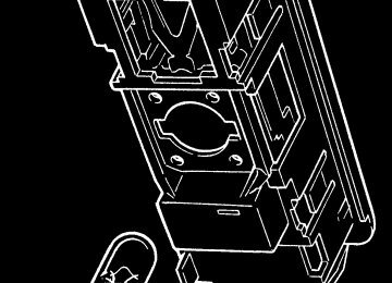
MAIN FUSEBOX
m254a
WARNING: Replacing a fuse with one which has a higher rating may cause extensive damage to the electrical system and pos- sibly cause a fire. If a fuse of the correct rating is not avail- able, use one of a lower rating as a temporary measure.
Fuse 1
Fuse 11
As viewed from in front
Fuse 12
Fuse 22
Slot Rate Circuit
15
Slot Rate Circuit 10 11
12 Aux pwr socket 20A Reverse lamps 13 5A Driver’s window 14 20A Pass. window 20A Stoplamps 10A Turn indicators 7.5A 10A Ignition services 16 7.5A Battery services 17 18 15A 7.5A Horn 19
10A 20
21
22
Alarm pwr interior lamp
Hazard lamps
ECU Ignition
1&2 slow, 1 fast
10A ABS 3A 20A Rad. fans;
7.5A Radio, switch
pack module 10A Parking lamps 10A Dip beam LH 10A Dip beam RH 20A A.C. comp. relay,
15A Main beam LH 15A Main beam RH 7.5A CDL
rad fan 2 fast
136
oh_croft_InD.indd 136
20/05/2004 07:59:15
ENGINE BAY FUSES
ohs136
Engine Compartment Fuses
Fuses associated with the engine management system are contained in two 4-position fuse holders located at the front of the engine bay on the cabin bulkhead, adjacent to the engine ECM. To access the fuses, unclip rear edge of the cover.
Fuse Rating Circuit R1 R2 R3 R4 R5 R6 R7 R8
20A 3A 5A 5A 5A 7.5A 10A 5A
Fuel pump Immobiliser Alternator sense ECU battery feed O2 heaters VSV's VVT, VVL, IAC Injectors, ignition coils Re-circ. pump
WARNING:
• To avoid injury, beware of rotating engine components and guard against entrapment of body parts, tools and loose clothing.
• Stop engine before servicing fuses. • Beware of hot surfaces in the engine bay. You could be
seriously burned if you touch a hot engine part.
• Take great care not to drop flammable liquids or objects
onto a hot engine and start a fire.
oh_croft_InD.indd 137
20/05/2004 07:59:15
137
Front
Fusebox ‘C’
Viewed from beneath
m248a
Footwell Sited Fuses
Four fuses are secured to the main wiring harness just ahead of the scuttle beam and accessible from the passenger footwell.
Fuse Rating Circuit C1 C2 C3 C4
20A 15A 7.5A 7.5A
Interior fan Wiper motor Audio key-in A.C. compressor
138
oh_croft_InD.indd 138
20/05/2004 07:59:15
l
Headlamp Alignment
The headlamps of your Elise were correctly adjusted during the manufacture of the car, and should only require subsequent adjustment if the headlamp assembly or front body is disturbed. Simply replacing the bulb will not affect alignment. Incorrectly adjusted headlamps can cause poor lighting performance or dazzle to oncoming traffic. Special headlamp setting equip- ment is required to correctly set the headlamps, such that only qualified technicians using appropriate equipment should be entrusted with this procedure:
1. Using beam setting equipment compatible with local regu- lations, position the machine between 300 and 700mm in front of the LH headlamp, and parallel with the two headlamp units using the sight bar or similar device dependent on the machine design, to ensure cross car match. Use the guides provided on the machine to ensure the correct height and lateral setting.
2. Switch on the headlamp low beams (uppermost lamps) and check the lateral beam alignment. The ‘knee point’ of the beam cut off line must lie within a tolerance of 2% to the pas- senger side, and 0%. Check the vertical alignment of the low beam which must lie within a tolerance of -0.5% and -2%.
oh_croft_InD.indd 139
20/05/2004 07:59:15
139
HEADLAMP COVER UNIT SOCKET BOLTS
ohs105a
3. If adjustment is required, the clear cover and mask must be removed from the body. From within the wheelarch, remove the access panel from the wheelarch liner to expose the headlamp cover retaining screws. Use the hexagonal key provided in the toolkit (in the rear pocket on the battery cover) to release the three socket head retaining screws and washers, and withdraw the cover assembly complete with rubber edge seal from the body. When refitting, do not overtighten the fixings.
4. To adjust the low beam laterally, adjust the dome headed screw at the upper inboard side of the low beam (uppermost) lamp, accessed from the front of the lamp. Turn clockwise to adjust the beam to the right. Optimum setting is 0%. To adjust the vertical aim of the low beam, adjust the dome headed screw at the lower outboard side of the lamp, accessed from the front of the lamp. Turn clockwise to raise the beam. Optimum setting is -1.5%.
5. Repeat for the RH lamp.
6. Centralise the machine on the LH high beam (lowermost) lamp, and switch on the high beams. Check the high beam alignment which should be centralised with the marker dot on the machine screen or slightly below the horizontal. Optimum setting is 0%.
140
oh_croft_InD.indd 140
20/05/2004 07:59:16
Vertical adjuster
Lateral adjuster
Lateral adjuster
High beam lamp
Vertical adjuster
Low beam lamp
m257
- To adjust the high beam laterally, adjust the dome headed screw at the upper inboard side of the lamp, accessed from behind the lamp. Turn clockwise to adjust the beam to the right.
- To adjust the vertical aim of the high beam, adjust the dome headed screw at the lower outboard side of the lamp, ac- cessed from behind the lamp. Turn clockwise to raise the beam.
7. Repeat for the RH lamp.
8. Re-fit the cover/mask assemblies complete with edge seal to the body, and secure with the three socket head screws and washers. Refit the wheelarch access panel.
141
oh_croft_InD.indd 141
20/05/2004 07:59:16
l
Low beam lamp
High beam lamp
Parking lamp bulb
ohs107
BULB REPLACEMENT
Headlamp Bulb
Mounted in the front body are the two headlamp units, each of which houses a halogen projector type low beam lamp (upper), and a halogen high beam lamp (lower) including the sidelamp bulb.
For access to the headlamp bulbs, first remove the clear cover
and mask from the body (see previous pages).
WARNING:
• Allow bulbs to cool before attempting removal, or your
fingers could be burnt.
• Halogen bulbs have pressurised gas inside and can burst if you drop or scratch the bulb. You or others could be injured.
• Be sure to read and follow instructions on the bulb
packaging.
NOTICE: Do not touch a halogen bulb glass envelope with the fingers, as the greasy deposit left behind will greatly reduce bulb life. Use a paper tissue to handle the bulb.
Low beam bulb: Disconnect the single cable, release the spring wire clip, and withdraw the 55W H1 bulb. On refitting, note that the bulb is keyed to allow only one orientation.
142
oh_croft_InD.indd 142
20/05/2004 07:59:16
RELEASING FRONT TURN LAMP
ohs149
High beam bulb: Disconnect the two cables from the bulb, re- lease the spring wire clip, and withdraw the 55W H7 bulb. On re- fitting, note that the bulb is keyed to allow only one orientation. Parking lamp: Twist the bulb holder counterclockwise to release from the main beam lamp, and withdraw the bayonet fitting T4 W bulb.
Front Turn Indicator Lamp Bulbs
For access to the front turn indicator bulb, the lamp unit must be released from the body. Using a suitable stiff rod or screw- driver blade inserted through the access hole in the outer top corner of the air intake aperture, press back the lamp retaining clip at the front end of the lamp, and withdraw the lamp from the body. Twist the bulb holder counterclockwise to release from the lamp, and replace the bayonet fitting amber bulb.
After replacing the bulb and holder, ensure the rubber seal is correctly positioned around the lamp. Engage the tongue at the rear end of the lamp unit with the body flange, and press the front end of the lamp firmly down until a distinct ‘click’ is heard, indicating engagement of the retaining clip. Pull up on the front end of the lamp to check security.
Side Repeater Lamp Bulbs
The side marker lamps mounted on the front and rear wheelarch lips, each use four longlife LEDs which are not serv- iceable. In case of failure, the lamp unit should be replaced by your dealer.
143
oh_croft_InD.indd 143
20/05/2004 07:59:16
REAR LAMP CLUSTERS
1 2 3 4 5 6
ohs110
Rear Lamp Cluster Bulbs
Each pair of rear lamps is configured as follows:
Outboard Lamp:
Outboard annulus; Central unit; Inboard annulus;
Inboard Lamp:
Outboard annulus; Central unit; Inboard annulus;
Tail and turn lamp Not used Turn lamp
Stop lamp Reverse lamp Stop and tail lamp
The bulbs for the rear lamps are accessible from within the rear luggage compartment. Twist the bulbholder counterclock- wise to remove, replace the bayonet fitting bulb, and refit the bulbholder.
High Mounted Stoplamp
The high mounted stoplamp, mounted beneath the rear window shroud uses light emitting diodes (LED) for optimum visibility. This is a self contained unit which may be replaced after releasing the two screws securing the housing to the body and unplugging the harness connector.
144
oh_croft_InD.indd 144
20/05/2004 07:59:17
INTERIOR LAMP BULB
ohs127
Licence Plate Lamps
To replace a bulb in a licence plate lamp, first remove the two screws securing the lamp, and withdraw. Replace the festoon bulb, and refit the lamp.
Interior Lamp
To withdraw the interior lamp from the rear bulkhead, first ease one end of the lamp from its aperture. Twist the bulbholder to release from the lamp body, and pull out the capless bulb.
Side Marker Lamps
The side marker lamps fitted to the front and rear wheelarch lips use light emitting diodes (LEDs) housed in a sealed lamp body. Replacement of a lamp assembly should be entrusted to your dealer.
145
oh_croft_InD.indd 145
20/05/2004 07:59:17
TOWING EYE FITMENT
LIFTING AND TOWING
ohs95
Towing Eye
A towing eye is stowed in the car tool kit, located in the battery cover rear pocket. When required, remove the protective bung (if fitted), and fit the towing eye to its anchorage point in the radiator air intake aperture, screwing fully into the tapped boss.
The eye is provided to aid car recovery, such as winching onto a flatbed car transporter, but only when the car is able to roll freely. Only in an emergency should the car be towed, and for the shortest distance necessary, during which time the fol- lowing precautions must be taken:
WARNING:
• Use only towing equipment designed specifically for this purpose, or damage to the car may be caused, or you could be killed or seriously injured.
• Ensure that the key is used to unlock the steering column, and is then left in the lock. Never withdraw the key until the car is stationary. The steering column will lock when the key is withdrawn.
• Release the parking brake and ensure that the trans-
mission is in neutral.
• Comply with all local legislation applicable to cars being
• Under no circumstances is the car to be secured using
towed.
the towing eye.
146
oh_croft_InD.indd 146
20/05/2004 07:59:17
Towing a Trailer
WARNING: The Elise is not suitable for towing a trailer.
Car Tie-Down
When moving a car by transporter or trailer, the car should be secured only by chocking and strapping around the road wheels. Attaching restraints around suspension linkages or chassis or body components may cause damage.
oh_croft_InD.indd 147
20/05/2004 07:59:17
147
LIFTING POINTS
Lifting Your Car
ohs49
WARNING:
• Using a lifting jack can be dangerous. If the car falls off the jack, you or others could be seriously injured or killed. NEVER get under a car when it is supported only by a jack.
• Before raising the car with a jack:
- Turn off the engine; - Firmly apply the parking brake; - Engage first or reverse gear; - Securely chock all wheels not to be lifted.
• Use only those lifting points identified above. Jacking at any other point, or with a jack improperly positioned, may damage the chassis or body structure and/or jeopardise safety.
Care must be taken when using a lifting jack or hoist to po- sition the device only in one of the areas shown in the illustration. Use a suitable rubber or timber pad to protect the chassis from surface damage: A; Identified by a blue sticker. Beneath crossmember ahead of fuel tank bay. To be used one side at a time for wheel chang- ing - lifts both wheels on one side.
B; Garage use with 4-point lift. Beneath the front end of the right
or left hand main chassis rail, behind the front wheelarch.
148
oh_croft_InD.indd 148
20/05/2004 07:59:18
C; Garage use with 4-point lift. Do not use if the diffuser panel is fitted. Beneath the outboard end of the chassis crossmember ahead of the rear wheelarches. Take care to position the jack between the fixing screws for the fuel tank bay perforated undershield. Avoid the fuel tank brackets.
D; Do not use if the diffuser panel is fitted. Beneath the rear subframe, close to the lower wishbone rearmost mountings.
NOTICE: In order fully to exploit the benefits of light weight, and to maximise stowage space, the Elise has no provision for spare wheel carriage or lifting jack. A temporary puncture repair facility is provided in the form of a tire inflator aerosol (see page 124).