- Download PDF Manual
-
20/05/2004 07:59:13
WARNING: When lifting the battery out of, or into the car, be aware of the considerable weight and take all appropriate precau- tions to safeguard personal health. Injury can result from improperly lifting the battery.
Keep the battery upright, and protect from sharp knocks
and shocks.
Reconnecting the Battery
WARNING: Failure to follow the correct battery re-connection pro-
cedure detailed above could result in serious burns.
Refit the battery, with its terminals outboard, by reversing the above procedure. Remember to push on the breather pipe (if applicable), and reconnect the battery cables as detailed below. Refit the battery cover. i) Check again that all electrical loads are switched off. ii) Connect the positive battery cable first, followed by the neg-
ative (earth) cable.
iii) After reconnection, a change in the engine performance characteristics may be noted for a period whilst the computer controlled engine management system ‘re-learns’ some of its settings.
iv) If necessary, enter the security code into audio equipment.
Battery Charging
Under conditions of normal daily use, it should not be nec- essary to use external battery charging equipment. In a low usage regime, however, it is important to maintain the charge state of the battery using a trickle charger, or an automatic bat- tery management conditioner such as that available through Lotus Dealers. Starting difficulties may be encountered after an unattended period of 3 weeks. A battery conditioner is able to continuously monitor battery charge state and switch on and off automatically in order to maintain the battery in a fully charged state without danger of damage through overcharging.
If the battery becomes discharged to the extent that the car cannot be started, the recommended course of action is to fit a substitute battery whilst the original battery is trickle
oh_croft_InD.indd 131
20/05/2004 07:59:13
131
l
charged. If, in an emergency, the car has to be ‘jump’ started, the subsequent conditions of car use may not allow for sufficient alternator charging of the battery to achieve a fully charged state. The battery should be trickle charged until 12.8 volts is recorded, which process may take 24 hours or longer. Putting the battery into service at a lower state of charge will reduce the time period for which the car can be parked. A battery left in a fully discharged state for a prolonged period, may not be recoverable to its original condition.
WARNING:
• Hydrogen gas generated by the battery could cause an
explosion, resulting in severe personal injuries.
• Charge battery in a well ventilated area. • Never charge a frozen battery. It may explode because of gas trapped in the ice. Allow a frozen battery to thaw out first. If you get electrolyte, which is an acid, in your eyes or on your skin, immediately rinse with cold water for several minutes and call a doctor.
•
Unless you are using an automatic battery management conditioner, the battery should be removed from the car for recharging, to a well ventilated area to avoid a build up of fumes in the luggage compartment and to prevent damage to the car's electrical system. Observe the safety precautions listed above when removing the battery and take care to avoid sharp knocks or shocks, keeping the battery as upright as possible. Beware of the considerable weight of a battery, and take necessary precautions against personal injury.
Check that the electrolyte level is between the upper and lower markers on the battery case, and if necessary add dis- tilled water. The recommended bench charge rate is 4 amps. When the battery is fully charged (12.8 volts), allow the battery to stand for an hour before refitting to the car and reconnecting the leads - see above.
132
oh_croft_InD.indd 132
20/05/2004 07:59:13
JUMP STARTING
ohs14c
‘Jump’ Starting
If the battery becomes discharged to the extent that the en- gine cannot be started, proprietary good quality ‘jumper cables’ may be used to connect with the battery of a second car in order to provide the energy necessary for starting.
WARNING: It is most important that the correct procedure is fol- lowed in order to avoid damage to either car’s electrical system, and most importantly, to minimise the danger of a spark induced battery explosion. Check that the slave car also has a NEGATIVE EARTH electrical system.
i) With the engine of the slave car running at a fast idle, use one jumper cable (red) to connect the positive (+) terminal of one battery to the positive terminal of the other battery. Take care during this process to avoid inadvertently earthing a free end of this cable to the metal body or chassis of either car. ii) Connect one end of the other jumper cable (black) to the
negative (-) terminal of the discharged battery.
iii) A spark will occur when the other end of this cable (the final connection) is connected to an earth on the slave car. This connection should therefore be made to a point away from the battery, and away from any fuel vapour area or moving parts. An engine hanger bracket is often ideal.
iv) Start the car in the usual way, and run at a fast idle.
133
oh_croft_InD.indd 133
20/05/2004 07:59:14
l
v) A spark will occur at the first disconnection of a jumper cable, so it is essential that the first disconnection is made from the slave car earth. Both batteries (especially the
discharged one) will be ‘gassing’ heavily at this time, and if the first disconnection is made at a battery terminal, there is a danger that the hydrogen gas may be ignited by the spark with a resultant explosion.
vi) Have the cause of the flat battery investigated and rectified,
and trickle charge the battery as detailed above.
WARNING:
shortcircuit.
• Risk of damage and serious personal injury due to
• Use only jumper cables of adequate cross-section, fitted with completely insulated alligator clamps. The cables must be long enough to allow that neither cars nor cables touch each other.
• Follow all warnings and instructions of the jumper cable
manufacturer.
• When connnecting the jumper cables, keep them away
from engine moving parts.
• The two cars must not contact each other, or current could
flow as soon as the positive terminals are connected.
• When the first clamp on each cable is connected, the other clamp on that cable must be held carefully to make sure it does not come into contact with either another cable clamp or either car.
• Ensure that tools or metal watches or jewellery do not
contact the battery terminals or live car parts.
NOTICE: •
Improper jumper cable connection can damage the alternator and other electrical components.
• Do not attempt to push or tow start the car, as damage to the
catalytic converter or other parts could be caused.
Electrical Accessories
Owners should note that the only approved extras and modi- fications are those which are specified by Lotus and carried out by Lotus or by an authorised dealer. Neither Lotus Cars Ltd. or Lotus Cars Inc. accept any liability whatsoever for defects which arise from extras or modifications which are not approved by Lotus Cars Ltd.
134
oh_croft_InD.indd 134
20/05/2004 07:59:14
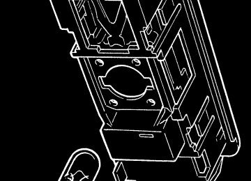
INERTIA SWITCH
ohs137
WARNING: Inexpert modifications or additions to the electrical
system could jeopardise safety.
Inertia Switch
The safety inertia switch is designed to operate on impact, typified by car collision, to switch off the fuel pump, and thus minimise any fire hazard. The central door locking will also be triggered to unlock the doors.
The inertia switch is mounted at the left hand bottom of the engine bay, on the inboard face of the rear subframe, and is ac- cessible from between the coolant header tank and windscreen washer reservoir. The switch is reset by pressing the rubber diaphragm button on the top of the unit.
Fuses
The main fusebox is located in the front services compartment, on the passenger side, and is protected by a plastic cover. For access, remove the passenger side front body access panel, and unclip the fusebox lid.
Twenty two slots are provided for ‘Littel’ type fuses which are numbered, and coloured according to their amperage rating, and may be pulled out from their slots using the fuse extractor tool provided on the fusebox lid.
135
oh_croft_InD.indd 135
20/05/2004 07:59:14
MAIN FUSEBOX
m254a
WARNING: Replacing a fuse with one which has a higher rating may cause extensive damage to the electrical system and pos- sibly cause a fire. If a fuse of the correct rating is not avail- able, use one of a lower rating as a temporary measure.
Fuse 1
Fuse 11
As viewed from in front
Fuse 12
Fuse 22
Slot Rate Circuit
15
Slot Rate Circuit 10 11
12 Aux pwr socket 20A Reverse lamps 13 5A Driver’s window 14 20A Pass. window 20A Stoplamps 10A Turn indicators 7.5A 10A Ignition services 16 7.5A Battery services 17 18 15A 7.5A Horn 19
10A 20
21
22
Alarm pwr interior lamp
Hazard lamps
ECU Ignition
1&2 slow, 1 fast
10A ABS 3A 20A Rad. fans;
7.5A Radio, switch
pack module 10A Parking lamps 10A Dip beam LH 10A Dip beam RH 20A A.C. comp. relay,
15A Main beam LH 15A Main beam RH 7.5A CDL
rad fan 2 fast
136
oh_croft_InD.indd 136
20/05/2004 07:59:15
ENGINE BAY FUSES
ohs136
Engine Compartment Fuses
Fuses associated with the engine management system are contained in two 4-position fuse holders located at the front of the engine bay on the cabin bulkhead, adjacent to the engine ECM. To access the fuses, unclip rear edge of the cover.
Fuse Rating Circuit R1 R2 R3 R4 R5 R6 R7 R8
20A 3A 5A 5A 5A 7.5A 10A 5A
Fuel pump Immobiliser Alternator sense ECU battery feed O2 heaters VSV's VVT, VVL, IAC Injectors, ignition coils Re-circ. pump
WARNING:
• To avoid injury, beware of rotating engine components and guard against entrapment of body parts, tools and loose clothing.
• Stop engine before servicing fuses. • Beware of hot surfaces in the engine bay. You could be
seriously burned if you touch a hot engine part.
• Take great care not to drop flammable liquids or objects
onto a hot engine and start a fire.
oh_croft_InD.indd 137
20/05/2004 07:59:15
137
Front
Fusebox ‘C’
Viewed from beneath
m248a
Footwell Sited Fuses
Four fuses are secured to the main wiring harness just ahead of the scuttle beam and accessible from the passenger footwell.
Fuse Rating Circuit C1 C2 C3 C4
20A 15A 7.5A 7.5A
Interior fan Wiper motor Audio key-in A.C. compressor
138
oh_croft_InD.indd 138
20/05/2004 07:59:15
l
Headlamp Alignment
The headlamps of your Elise were correctly adjusted during the manufacture of the car, and should only require subsequent adjustment if the headlamp assembly or front body is disturbed. Simply replacing the bulb will not affect alignment. Incorrectly adjusted headlamps can cause poor lighting performance or dazzle to oncoming traffic. Special headlamp setting equip- ment is required to correctly set the headlamps, such that only qualified technicians using appropriate equipment should be entrusted with this procedure:
1. Using beam setting equipment compatible with local regu- lations, position the machine between 300 and 700mm in front of the LH headlamp, and parallel with the two headlamp units using the sight bar or similar device dependent on the machine design, to ensure cross car match. Use the guides provided on the machine to ensure the correct height and lateral setting.
2. Switch on the headlamp low beams (uppermost lamps) and check the lateral beam alignment. The ‘knee point’ of the beam cut off line must lie within a tolerance of 2% to the pas- senger side, and 0%. Check the vertical alignment of the low beam which must lie within a tolerance of -0.5% and -2%.
oh_croft_InD.indd 139
20/05/2004 07:59:15
139
HEADLAMP COVER UNIT SOCKET BOLTS
ohs105a
3. If adjustment is required, the clear cover and mask must be removed from the body. From within the wheelarch, remove the access panel from the wheelarch liner to expose the headlamp cover retaining screws. Use the hexagonal key provided in the toolkit (in the rear pocket on the battery cover) to release the three socket head retaining screws and washers, and withdraw the cover assembly complete with rubber edge seal from the body. When refitting, do not overtighten the fixings.
4. To adjust the low beam laterally, adjust the dome headed screw at the upper inboard side of the low beam (uppermost) lamp, accessed from the front of the lamp. Turn clockwise to adjust the beam to the right. Optimum setting is 0%. To adjust the vertical aim of the low beam, adjust the dome headed screw at the lower outboard side of the lamp, accessed from the front of the lamp. Turn clockwise to raise the beam. Optimum setting is -1.5%.
5. Repeat for the RH lamp.
6. Centralise the machine on the LH high beam (lowermost) lamp, and switch on the high beams. Check the high beam alignment which should be centralised with the marker dot on the machine screen or slightly below the horizontal. Optimum setting is 0%.
140
oh_croft_InD.indd 140
20/05/2004 07:59:16
Vertical adjuster
Lateral adjuster
Lateral adjuster
High beam lamp
Vertical adjuster
Low beam lamp
m257
- To adjust the high beam laterally, adjust the dome headed screw at the upper inboard side of the lamp, accessed from behind the lamp. Turn clockwise to adjust the beam to the right.
- To adjust the vertical aim of the high beam, adjust the dome headed screw at the lower outboard side of the lamp, ac- cessed from behind the lamp. Turn clockwise to raise the beam.
7. Repeat for the RH lamp.
8. Re-fit the cover/mask assemblies complete with edge seal to the body, and secure with the three socket head screws and washers. Refit the wheelarch access panel.
141
oh_croft_InD.indd 141
20/05/2004 07:59:16
l
Low beam lamp
High beam lamp
Parking lamp bulb
ohs107
BULB REPLACEMENT
Headlamp Bulb
Mounted in the front body are the two headlamp units, each of which houses a halogen projector type low beam lamp (upper), and a halogen high beam lamp (lower) including the sidelamp bulb.
For access to the headlamp bulbs, first remove the clear cover
and mask from the body (see previous pages).
WARNING:
• Allow bulbs to cool before attempting removal, or your
fingers could be burnt.
• Halogen bulbs have pressurised gas inside and can burst if you drop or scratch the bulb. You or others could be injured.
• Be sure to read and follow instructions on the bulb
packaging.
NOTICE: Do not touch a halogen bulb glass envelope with the fingers, as the greasy deposit left behind will greatly reduce bulb life. Use a paper tissue to handle the bulb.
Low beam bulb: Disconnect the single cable, release the spring wire clip, and withdraw the 55W H1 bulb. On refitting, note that the bulb is keyed to allow only one orientation.
142
oh_croft_InD.indd 142
20/05/2004 07:59:16
RELEASING FRONT TURN LAMP
ohs149
High beam bulb: Disconnect the two cables from the bulb, re- lease the spring wire clip, and withdraw the 55W H7 bulb. On re- fitting, note that the bulb is keyed to allow only one orientation. Parking lamp: Twist the bulb holder counterclockwise to release from the main beam lamp, and withdraw the bayonet fitting T4 W bulb.
Front Turn Indicator Lamp Bulbs
For access to the front turn indicator bulb, the lamp unit must be released from the body. Using a suitable stiff rod or screw- driver blade inserted through the access hole in the outer top corner of the air intake aperture, press back the lamp retaining clip at the front end of the lamp, and withdraw the lamp from the body. Twist the bulb holder counterclockwise to release from the lamp, and replace the bayonet fitting amber bulb.
After replacing the bulb and holder, ensure the rubber seal is correctly positioned around the lamp. Engage the tongue at the rear end of the lamp unit with the body flange, and press the front end of the lamp firmly down until a distinct ‘click’ is heard, indicating engagement of the retaining clip. Pull up on the front end of the lamp to check security.
Side Repeater Lamp Bulbs
The side marker lamps mounted on the front and rear wheelarch lips, each use four longlife LEDs which are not serv- iceable. In case of failure, the lamp unit should be replaced by your dealer.
143
oh_croft_InD.indd 143
20/05/2004 07:59:16
REAR LAMP CLUSTERS
1 2 3 4 5 6
ohs110
Rear Lamp Cluster Bulbs
Each pair of rear lamps is configured as follows:
Outboard Lamp:
Outboard annulus; Central unit; Inboard annulus;
Inboard Lamp:
Outboard annulus; Central unit; Inboard annulus;
Tail and turn lamp Not used Turn lamp
Stop lamp Reverse lamp Stop and tail lamp
The bulbs for the rear lamps are accessible from within the rear luggage compartment. Twist the bulbholder counterclock- wise to remove, replace the bayonet fitting bulb, and refit the bulbholder.
High Mounted Stoplamp
The high mounted stoplamp, mounted beneath the rear window shroud uses light emitting diodes (LED) for optimum visibility. This is a self contained unit which may be replaced after releasing the two screws securing the housing to the body and unplugging the harness connector.
144
oh_croft_InD.indd 144
20/05/2004 07:59:17
INTERIOR LAMP BULB
ohs127
Licence Plate Lamps
To replace a bulb in a licence plate lamp, first remove the two screws securing the lamp, and withdraw. Replace the festoon bulb, and refit the lamp.
Interior Lamp
To withdraw the interior lamp from the rear bulkhead, first ease one end of the lamp from its aperture. Twist the bulbholder to release from the lamp body, and pull out the capless bulb.
Side Marker Lamps
The side marker lamps fitted to the front and rear wheelarch lips use light emitting diodes (LEDs) housed in a sealed lamp body. Replacement of a lamp assembly should be entrusted to your dealer.
145
oh_croft_InD.indd 145
20/05/2004 07:59:17
TOWING EYE FITMENT
LIFTING AND TOWING
ohs95
Towing Eye
A towing eye is stowed in the car tool kit, located in the battery cover rear pocket. When required, remove the protective bung (if fitted), and fit the towing eye to its anchorage point in the radiator air intake aperture, screwing fully into the tapped boss.
The eye is provided to aid car recovery, such as winching onto a flatbed car transporter, but only when the car is able to roll freely. Only in an emergency should the car be towed, and for the shortest distance necessary, during which time the fol- lowing precautions must be taken:
WARNING:
• Use only towing equipment designed specifically for this purpose, or damage to the car may be caused, or you could be killed or seriously injured.
• Ensure that the key is used to unlock the steering column, and is then left in the lock. Never withdraw the key until the car is stationary. The steering column will lock when the key is withdrawn.
• Release the parking brake and ensure that the trans-
mission is in neutral.
• Comply with all local legislation applicable to cars being
• Under no circumstances is the car to be secured using
towed.
the towing eye.
146
oh_croft_InD.indd 146
20/05/2004 07:59:17
Towing a Trailer
WARNING: The Elise is not suitable for towing a trailer.
Car Tie-Down
When moving a car by transporter or trailer, the car should be secured only by chocking and strapping around the road wheels. Attaching restraints around suspension linkages or chassis or body components may cause damage.
oh_croft_InD.indd 147
20/05/2004 07:59:17
147
LIFTING POINTS
Lifting Your Car
ohs49
WARNING:
• Using a lifting jack can be dangerous. If the car falls off the jack, you or others could be seriously injured or killed. NEVER get under a car when it is supported only by a jack.
• Before raising the car with a jack:
- Turn off the engine; - Firmly apply the parking brake; - Engage first or reverse gear; - Securely chock all wheels not to be lifted.
• Use only those lifting points identified above. Jacking at any other point, or with a jack improperly positioned, may damage the chassis or body structure and/or jeopardise safety.
Care must be taken when using a lifting jack or hoist to po- sition the device only in one of the areas shown in the illustration. Use a suitable rubber or timber pad to protect the chassis from surface damage: A; Identified by a blue sticker. Beneath crossmember ahead of fuel tank bay. To be used one side at a time for wheel chang- ing - lifts both wheels on one side.
B; Garage use with 4-point lift. Beneath the front end of the right
or left hand main chassis rail, behind the front wheelarch.
148
oh_croft_InD.indd 148
20/05/2004 07:59:18
C; Garage use with 4-point lift. Do not use if the diffuser panel is fitted. Beneath the outboard end of the chassis crossmember ahead of the rear wheelarches. Take care to position the jack between the fixing screws for the fuel tank bay perforated undershield. Avoid the fuel tank brackets.
D; Do not use if the diffuser panel is fitted. Beneath the rear subframe, close to the lower wishbone rearmost mountings.
NOTICE: In order fully to exploit the benefits of light weight, and to maximise stowage space, the Elise has no provision for spare wheel carriage or lifting jack. A temporary puncture repair facility is provided in the form of a tire inflator aerosol (see page 124).
Fuel Tank Undershield
WARNING: The perforated panel enclosing the underside of the fuel tank bay, contributes to the structural rigidity of the chassis frame. Do not use the car with this panel removed.
oh_croft_InD.indd 149
20/05/2004 07:59:18
149
s
ACCESSORIES
Accessories and Modifications
Modifying your car, or installing some non-Lotus accessories, can make your car unsafe. Before you make any modifications or add any accessories, be sure to read the following information and confer with your dealer:
Accessories:
Your dealer has genuine Lotus accessories that allow you to personalise your car. These accessories have been designed and approved for your car, and are covered by warranty.
Non-Lotus accessories may be designed for universal ap- plication, and although they may fit on your car, they may not meet factory specifications, and could adversely affect your car’s handling and stability.
WARNING: Improper accessories or modifications can affect your car’s handling, stability and performance, and cause a crash in which you can be hurt or killed. Follow all instruc- tions in this owner’s manual regarding accessories and modifications.
When properly installed, cellular phones, alarms, two-way radios, and low powered audio systems should not interfere with your car’s computer-controlled systems, such as the airbag and anti-lock brake system.
However, if such or similar electronic accessories are im- properly installed, or exceed your car’s electrical system ca- pacity, they can interfere with the operation of your car, cause the airbags to deploy, or damage the car.
Before installing any accessory:
• Ensure the accessory does not obscure any lights, or interfere
with proper car operation or performance.
• Ensure electronic accessories do not overload electrical
circuits.
• Have the installer contact your Lotus dealer for assistance
before installing any electronic accessory. If possible, have your Lotus dealer inspect the final instal- lation.
•
150
oh_croft_InD.indd 150
20/05/2004 07:59:18
Important Safety Information About Modifications
Do not remove any original equipment or modify your car in any way that would alter its design or operation. This could make your car unsafe or illegal to drive.
For example, do not install wheels and tires with a differ- ent overall diameter. Such modifications can adversely affect handling, and interfere with the operation of the car’s anti-lock brakes and other systems.
In addition, any modifications that decrease ground clearance beyond Lotus approval, increase the chance of undercarriage parts striking a kerb, speed bump, or other raised object, which could cause your airbags to deploy as well as damaging the chassis and body underside.
Do not modify your steering wheel or any other part of your air- bag system. Modifications could make the system ineffective.
WARNING: Do not attach or place objects on the airbag covers. Any object attached to or placed on the covers marked ‘AIRBAG’, in the centre of the steering wheel and on top of the dashboard, could interfere with the proper operation of the airbags. Or, if the airbags inflate, the objects could be propelled inside the car and hurt someone.
151
oh_croft_InD.indd 151
20/05/2004 07:59:18
Storing Your Elise
If you intend to store your Elise for a prolonged period, con- sult your Lotus dealer who will be pleased to advise you. We recommend that the car is stored inside a secure garage. The following guidelines are provided for your information: • Ensure the engine oil and filter, coolant and brake fluid have recently been renewed. The a.c. system should be in good working order and fully charged. • Thoroughly clean the inside and outside of the car, including the engine compartment. If necessary, use a ‘jet’ washer to remove dirt and salt deposits from the underside, but do not use around bearings, hydraulic components, painted surfaces or the soft top roof. Allow to dry completely. • Chock the road wheels, leave off the parking brake, and •
engage reverse gear. Increase the tire pressures to 60 psi (4 bar). If possible, move the car slightly every month to help avoid flat spots on the Tires. • Either leave the battery in the car and connect a battery management (conditioner) type of charger, or remove the battery and trickle charge every two months. Note that with the battery disconnected or removed, the alarm system is de-activated. • Unless the garage is equipped with a de-humidifier, the use of drying agents (Silica-Gel) is recommended in cars with leather upholstery and in conditions of high humidity. • The use of unapproved car covers may have a detrimental effect on the car’s paint finish and such damage will not be covered by your car’s warranty.
In general, the Elise will be kept in best operating condition
by regular use.
152
oh_croft_InD.indd 152
20/05/2004 07:59:19
RECOMMENDED LUBRICANTS
Engine
In order to enhance the longevity and reliability of the car, it is most important that only the specified lubricants are used. It is an entirely false economy to try to save money by using lower quality oils, which may break down before the next change in- terval and provide inadequate protection before the end of the term. High oil consumption may also result.
For topping up purposes during the running-in period prior to the First After Sales Service, a top quality mineral or semi-syn- thetic 5W/40 oil should be used. At the First After Sales Service and completion of the running-in period, a fully synthetic 5W/40 oil such as Texaco Havoline Synthetic should be used. This oil has been tested in all climatic conditions likely to be encountered, and offers advantages in ease of cranking, smooth cold running and fuel economy at low temperatures, in combination with good wear protection at elevated temperatures and at high engine speeds. If Texaco/Havoline products are not available, an oil meeting the following specification should be used.
NOTICE: Note that Lotus does not recommend the use of any oil additives and use of such additives may invalidate the terms of your car’s warranty.
5W/40
API SJEC; ILSAC; ACEA A3 4.4 litreViscosity: Quality Standard: Capacity - refill inc. filter (Cars fitted with front mounted oil coolers contain an additional 3.5 litres, but this oil is not drained during routine servicing) Difference between high & low dipstick marks
Oil change interval
1.5 litre Refer to Maintenance Schedule
‘Severe Service’ Conditions
Certain operating conditions can cause rapid degradation of the oil quality, either by the accumulation of dirt particles, or by the absorption of water from condensation. If any of the ‘severe service’ conditions described below apply, it is recommended that the oil and filter be changed twice as frequently as is listed in the Maintenance Schedule.
153
oh_croft_InD.indd 153
20/05/2004 07:59:19
• Driving in dusty areas (e.g. on unmetalled roads); Change the oil and filter as soon as possible after driving in a dust storm.
• Stop/start driving with frequent short trips where the engine rarely warms up thoroughly (especially in cold weather/cli- mates); and/or frequent or prolonged idling.
• Track use, with repeated high rpm, wide throttle openings and high oil temperatures. For appropriate maintenance, dis- cusswith your Lotus dealer. Note that use of the car off road or in a competitive manner, including timed runs or laps, will invalidate warranty and require appropriate levels of expert car preparation and servicing.
Transmission (gearbox & final drive) Viscosity Quality Standard Capacity Oil change interval
SAE 75W/90
API GL-4 or GL-5
2.3 litre (2.4 US qt) Refer to Maintenance ScheduleBrake & Clutch System Type
Specification Capacity - brake - clutch
Fluid change interval
Engine Coolant Additive Only approved product Type OAT Colour Concentration Quantity reqd. @ 50%
Non-mineral (non-petroleum) hydraulic fluid DOT 4
1.5 litre 0.5 litre 12 monthsHavoline XLC Ethylene glycol antifreeze with corrosion inhibitors Orange 50% 6 litres
154
oh_croft_InD.indd 154
20/05/2004 07:59:19
TECHNICAL DATA
- sport option - rear
- std. - sport option - front - std. - sport option - rear
Tires - Standard Type
Size
Pressure (cold) - front - std.
Winter Tires - front Type - rear
- front Size - rear
Pressure (cold) - front
- rear Wheels Type
Size
Wheel bolt torque Dimensions
Overall length - excl. mirrors Overall width - incl. mirrors
Overall height (at kerb weight) Wheelbase Track
Ground clearance (mid laden)
Front overhang Rear overhang Approach angle (at kerb) (sport) Departure angle (at kerb) (sport) 23°
- std. - sport option - front - std. - sport option - rear
- front - rear
- std. - sport
Yokohama Neova AD07
Yokohama A048
175/55 R16 195/50 R16 84W 225/45 R17 90W 180kPa (26 psi) 180kPa (26 psi) 200kPa (29psi)Pirelli 210 Snowsport Pirelli 240 Snowsport 195/50 R16 215/45 R17 180kPa (26 psi) 190kPa (27.5 psi)
Cast alloy, 8 spoke Forged alloy, 7 twin-spoke 5.5J x 16 6.5J x 16
7.5J x 17 105 Nm (77 lbf.ft)3785 mm 1719 mm 1850 mm (approx.) 1117 mm 2300 mm 1457 mm 1503 mm
135 mm 130 mm 783 mm 702 mm 13.5°
155
oh_croft_InD.indd 155
20/05/2004 07:59:19
a
Unladen weight - total - front (heaviest)
- rear - total Max. weight - front
- rear
Trailer towing
inc. 912 kg full fuel 344 kg tank 568 kg incl. 1162 kg > 441 kg > occupants 721 kg > & luggage Not permissible
4.7 U.S. qt. (4.4 litre)
Capacities Engine oil (refill inc. filter) (+3.7 U.S. qt (3.5) litre if front mounted oil coolers are drained) High/low dipstick mark difference Transmission oil Fuel tank Cooling system A.C. refrigerant (R134a)
1.6 U.S. qt. (1.5 litre) 2.4 U.S. qt. (2.3 litre) 10.6 U.S. gall. (40 litre) 12.7 U.S. qt. (12 litre) 1.2 lb (0.55 kg)
Front Suspension Type
Steering axis inclination
Independent. Upper and lower wishbone co-axial coil spring/telescopic damper unit; anti-roll bar 12° nominal
Geometry specification - Standard: Mid-laden ride height (reference height for geometry check)
135 mm below front end of chassis siderail 135 mm below rear end of chassis siderail + 3.8°
- front
- rear
- optimum - tolerance range + 3.5° to + 4.1°;
- optimum - tolerance range + 0.1° to - 0.3°
- optimum - tolerance range 0.5 mm toe-out, to 0.7mm toe-in overall
max. side/side 0.35° - 0.1°
max. side/side 0.2° Zero
Castor
Camber
Alignment
156
oh_croft_InD.indd 156
20/05/2004 07:59:19
Geometry specification - Sport option: Mid-laden ride height (reference height for geometry check)
Castor
Camber
Alignment
130 mm below front end of chassis siderail 130 mm below rear end of chassis siderail + 3.8°
- front
- rear
- optimum - tolerance range + 3.5° to + 4.1°;
- optimum - tolerance range - 0.1° to - 0.5°
- optimum - tolerance range 0.5 mm toe-out, to 0.5 mm toe-in overall
max. side/side 0.35° - 0.3°
max. side/side 0.2° Zero
Independent. Upper and lower wishbone; co-axial coil spring/telescopic damper.
Rear Suspension Type
Geometry specification - Standard: Mid-laden ride height (reference height for geometry check) 135 mm below front end
of chassis siderail 135 mm below rear end
of chassis siderail
Camber - 1.8°
Alignment
- front
- rear
- optimum - tolerance range - 1.6° to - 2.0° max.side/side 0.2°
- optimum 1.2 mm toe-in each side - tolerance range 1.2 to 1.8mm toe-in each
side max.side/side 0.3 mm
Geometry specification - Sport option: Mid-laden ride height (reference height for geometry check)
- front
- rear
130 mm below front end of chassis siderail 130 mm below rear end of chassis siderail
157
oh_croft_InD.indd 157
20/05/2004 07:59:20
Camber
Alignment
- 1.8°
- optimum - tolerance range - 1.6° to - 2.0°
- optimum - tolerance range 1.2 to 1.8 mm toe-in each
max.side/side 0.2° 1.5 mm toe-in each side
side max.side/side 0.3 mm
Electrical Light Bulbs Headlamps Front side/parking lamps Front turn indicators Rear turn indicators Side repeater lamps Stop lamps Tail/stop lamps Tail/turn lamps High mounted stop lamp Reversing lamp Licence plate lamps Interior lamp
H1 & H7
W5W PY21w amber H21
WY5W amber H21Watt. Type 55 21 21 21 4/21 P21/4w 4/21 P21/4w 2.5 21
16 x LED H21
C5W W5WSystem voltage/polarity Alternator Battery (service replacement)
- type - BCI code - cranking power - reserve capacity
12V negative earth 85A
Delco 19001598
26R-6YR 550 amps @ -18°C 80 minutesEngine Type designation Cylinder configuration Capacity Bore Stroke Camshafts Valve actuation
Compression ratio Firing order
- inlet - exhaust
2ZZ-GE in-line 4
1796 cm3 82.0 mm 85.0 mm Chain driven DOHC 4VPC Variable timing and lift Variable lift 11.5:1
1,3,4,2158
oh_croft_InD.indd 158
20/05/2004 07:59:20
Spark plugs
Spark plug gap Max. continuous engine speed Fuel requirement Minimum octane Fuel system
Peak power (SAE DIN 70020)
Peak torque (SAE DIN 70020)
NGK IFR6A11
DensoSK20R11
1.1 mm 8000 rpm (8500 transient) Unleaded 91 (RON+MON)/2
Multi-point fully sequential fuel injection with Lotus T4 controller. 190 bhp (141.7 kW) @ 7,800 rpm 138 lbf.ft (187 Nm) @ 6,800 rpmTransmission Type
Ratio Gear 3.17:1 First 2.05:1 Second 1.48:1 Third 1.17:1 Fourth 0.92:1 Fifth Sixth 0.81:1 Reverse 3.25:1
6 speed manual transaxle. Bevel gear differential.
Final Drive mph/1000 rpm ) 4.53:1
5.1 7.7 10.7 13.6 17.3 19.4
Brakes Type
Disc Size - front and rear Operation
Parking Brake
Front and rear discs with curved vane ventilation and cross drilling. AP Racing aluminium op posed piston front calipers. Single piston sliding rear calipers. 288mm Tandem master cylinder with vacuum servo and ABS Cable operation of rear calipers, self adjusting for pad wear.
oh_croft_InD.indd 159
20/05/2004 07:59:20
159
a
160
oh_croft_InD.indd 160
20/05/2004 07:59:20
WARRANTY INDEX
Limited Warranty ................................................................. 162
Warranty Periods ........................................................... 162Limitations ..................................................................... 163
Exclusive Remedies ...................................................... 163
Extent of Company Obligations ..................................... 163
Exclusions From Warranty Coverage ............................ 164Obligations of Owners ...................................................167
Exclusive Warranty ....................................................... 168
Customer Assistance .................................................... 168
Lotus Federal Emission Control System Warranties ...........171
Emissions Defects Warranty ..........................................171Emissions Performance Warranty ..................................172
Required Maintenance .................................................. 173What is Not Covered ......................................................174
Improper Maintenance and Use .....................................175
Warranty Claim Procedure ............................................ 176
Further Information ........................................................ 178Emissions Warranty Parts List ...................................... 178
California Emission Control Warranty Statement ............... 180Lotus California Emission Control System Warranties ....182
California Emission Control System Defects Warranty ... 182California Emissions Performance Warranty ................ 185
What Is Not Covered By The California Emission Warranty 186
Customer Assistance .....................................................187
7 Year/70,000 Mile Emissions Defects Warranty Parts List 187161
oh_croft_InD.indd 161
20/05/2004 07:59:20
y
LIMITED WARRANTY
Lotus Cars U.S.A. Inc.; 2236 Northmont Parkway, Duluth,
Georgia 30096.
LOTUS CARS U.S.A. Inc., (the Company) warrants each new Lotus motor car sold by the Company or an authorised Lotus dealer* in the U.S.A., and each Lotus replacement part supplied by the Company or an authorised Lotus dealer* in the U.S.A., to be free from defects in material and workmanship under normal use and service, and subject to the terms and conditions in this Limited Warranty, for the applicable Warranty Period set forth in Paragraph 1. (*Authorised Lotus dealers are not owned by, or are agents of, the Company)
The paragraphs below are the only and exclusive rem-
edies under the terms of the warranty.
The Limited Warranty excludes certain parts and sets of
circumstances which are set out in section 4 below.
1. WARRANTY PERIODS
(a) LIMITED WARRANTY - Cars.
The Company warrants each new car to be free from defects in material and workmanship for a period of thirty six (36) months or 36,000 miles, whichever first occurs, after the first occurring of the following dates:
i) date of delivery of the car to the retail original owner; ii) registration as a dealer demonstrator.
CONSULT YOUR SALES DOCUMENTS TO DETERMINE THE WARRANTY START DATE ON YOUR CAR; SPEAK TO YOUR DEALER OR LOTUS CARS USA IF YOU ARE IN DOUBT.
(b) LIMITED WARRANTY - Replacement Parts.
Genuine Lotus replacement parts are warranted to be free from defects in materials and workmanship for 12 months from the date of their installation or until the expiration of the car’s limited warranty term, whichever occurs last.
162
oh_croft_InD.indd 162
20/05/2004 07:59:20
y
(c) LIMITED WARRANTY - Corrosion Perforation.
The Company’s Limited Corrosion Perforation Warranty (as set forth in Paragraph 4 (c)) runs for a period of 8 years from the commencement of the Car Limited Warranty as specified in paragraph 1(a).
2. LIMITATIONS
THE COMPANY DOES NOT AUTHORIZE ANY PERSON TO CREATE ANY OTHER OBLIGATION IN CONNECTION WITH ITS CARS. ANY IMPLIED WARRANTY OF MERCHANT- ABILITY OR FITNESS FOR A PARTICULAR PURPOSE, AP- PLICABLE TO A CAR OR PART IS LIMITED IN DURATION TO THE TIME PERIODS SET FORTH IN PARAGRAPH 1.
3. EXCLUSIVE REMEDIES
THE PERFORMANCE OF REPAIRS AND NEEDED AD- JUSTMENTS ARE THE EXCLUSIVE REMEDIES UNDER THIS WRITTEN WARRANTY OR ANY IMPLIED WARRANTY. THE COMPANY SHALL NOT BE LIABLE FOR INCIDENTAL OR CONSEQUENTIAL DAMAGE RESULTING FROM THE BREACH OF ANY WARRANTY.
SOME STATES DO NOT ALLOW LIMITATIONS ON HOW LONG AN IMPLIED WARRANTY LASTS, OR THE EXCLUSION OR LIMITATION OF INCIDENTAL OR CONSE- QUENTIAL DAMAGES, SO THE ABOVE LIMITATIONS OR EXCLUSIONS MAY NOT APPLY TO YOU.
4. EXTENT OF COMPANY OBLIGATIONS
(a) LIMITED WARRANTY - Car. This warranty extends to each original and subsequent owner of a Lotus motor car within the warranty period expressed in Paragraph 1(a). The obligations of the Company under this warranty are limited to the repair or, at its option, the replacement with a new or remanufactured unit without charge for labour or part, of any part or assembly or component determined to be defective in material or workmanship during the applicable warranty period. All items which are replaced become the property of the Company to the fullest extent allowed under applicable law. All Service under this warranty must be performed by a Lotus Dealer at its place of business.
oh_croft_InD.indd 163
20/05/2004 07:59:21
163
y
(b) LIMITED WARRANTY - Replacement Parts.
The obligations of the Company during the warranty term are limited to the repair or, at its option, the replacement of any genuine Lotus part determined to be defective in mate- rial or workmanship during the warranty period expressed in paragraph 1(b). All replaced parts shall become the property of the Company.
(c) LIMITED WARRANTY - Corrosion Perforation.
The Company warrants to the original owner and each subse- quent owner during the warranty period set forth in Paragraph 1(c), that if corrosion perforation occurs on the chassis or com- posite body structure of a Lotus motor car, within the warranty period expressed in Paragraph 1(c), the parts or components affected by such perforation shall be repaired or replaced, without charge for labour or parts. Provided, however, that:
a) the Lotus car must be brought to an authorised Lotus dealer
for inspection at least one time each year; and
b) the Lotus car has been used and maintained in a normal
and reasonable manner.
c) corrosion perforation is not due to any or all of the follow- ing: an accident; abuse; damage; installation of an accessory; chemical substance; an act of nature; fire; or salvaged car.
(d) OBTAINING REPAIRS.
All warranted repairs will be effected at Lotus Dealers upon presentation of suitable evidence of eligibility. A reasonable time must be allowed for the dealership to perform necessary repairs, and customers are requested to allow such a reason- able amount of time. It is not Lotus Cars USA’s responsibility to provide the customer with a loan car during these repairs. The provision of a loan car should be discussed with the dealer.
5. EXCLUSIONS FROM WARRANTY COVERAGE (see also section 6)
(a) TIRES. The only provided warranty for tires is the written warranty issued by the tire supplier and included with the owner literature supplied with your car. (b) CAR SPECIFICATION. The obligations of the Company under this Limited Warranty apply only to cars built by the manufacturer to USA specification for road use (i.e. not to
164
oh_croft_InD.indd 164
20/05/2004 07:59:21
y
cars imported into the USA which are not manufactured to a USA specification.
(c) MAINTENANCE; SERVICE ITEMS; WEAR & TEAR.
Maintenance services are not covered, these include (al-
though this list is not exhaustive): i) maintenance services such as tune-ups, cleaning, polishing, lubrication, wheel balancing and alignment, brake, clutch, belt and other normal adjustments, ii) recharging or replacement of the battery where the car is not used for prolonged periods and a battery charger is not used, iii) the repair or replacement of service items such as lubri- cants, fluids, spark plugs, wiper blades, filters, belts, hoses, brake pads and linings clutch components, light bulbs or glass, or, iv) after the first three months of service (unless as part of a warranty repair), the air conditioner refrigerant, or
v) the deterioration of paintwork, upholstery (see para 5n) or any other part, assembly or component as a consequence of normal wear and tear or exposure to the elements, including airborne fallout (chemicals, tree sap etc.).
vi) body panel, glass and trim adjustments may intermittently be required to prevent excessive water ingress, or noise and vibration and so should be considered as routine mainte- nance.