- Download PDF Manual
-
sensor.
on.
Emergency disarming/mobilising
If the transmitter fobs are lost or damaged, the alarm system owner’s unique PIN may be used to disarm the alarm and/or mobilise the engine provided that access is available to the cabin. Follow the transmitter fob programming instructions (see page 18) from step 3.
oh_croft_InD.indd 33
20/05/2004 07:58:47
33
Microwave sensor
ohs120
Intrusion Sensing
A microwave sensor is mounted behind the cabin rear bulkhead trim panel, and is able to detect substantial physical movement within the cockpit, and trigger the alarm. Microwave transmissions are blocked by metal objects, so it is important not to shield the signal by placing such items on the bulkhead ledge.
If desired, the alarm may be armed without the intrusion sensor or battery interruption circuits being active by arming the system in the usual way with the transmitter larger button, and within 20 seconds, pressing the smaller button twice.
Manual Activation of Siren
To enhance personal security, with the system in a fully armed state (after 45 second arming period), the siren may be manually triggered by pressing the transmitter smaller button. The siren will sound and the turn lamps flash for 15 seconds. To stop the siren, press either of the two transmitter buttons.
34
oh_croft_InD.indd 34
20/05/2004 07:58:47
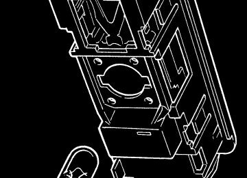
Transmitter casing
Transmitter body
Battery
ohs102
Transmitter Fob Battery Replacement
The transmitter fobs will normally operate within a range of 5 metres from the car, but this may be reduced by the presence of other radio signals in the vicinity. A small LED tell tale on the transmitter fob will flash whilst the button is held down to indicate correct operation, but if the lamp flashes irregularly or only once, transmitter battery replacement is required.
The transmitters are powered by a long life 3V Lithium battery, type CR2032, which with normal use should last for 3 years. To ensure continuity of operation, it is recommended to renew the batteries every 12 months: - Using a small screwdriver, prise open the case in the areas
marked ‘open’.
- Remove the old battery and wait for 10 seconds before insert- ing the new battery with +ve sign uppermost, and holding the battery only by the periphery.
- Align the locating studs, and firmly press the case together. - The transmitter should now operate normally, but may require
re-synchronisation with the control unit.
Transmitter Re-synchronisation
If at any time the transmitter does not function, and the battery is known to be good, carry out the following re-synchronisation procedure: - Stand close to the car and hold down both buttons on the transmitter until the LED on the fob is extinguished (approx. 10 seconds).
35
oh_croft_InD.indd 35
20/05/2004 07:58:48
- Release both buttons; the fob tell tale should come on con-
stantly.
- Press the larger button for one second (the fob tell tale will
flash). Synchronisation is complete.
Programming Additional Transmitter Fobs
Two transmitter fobs are provided with the new car. If one transmitter is lost or damaged, a replacement should be ob- tained immediately from your dealer, and programmed to the car alarm controller using a functioning transmitter fob and the system owner’s unique Personal Identification Number (PIN). Up to 4 transmitter fobs can be matched with the alarm system, but all fobs must collectively undergo the single programming operation: 1. Press, simultaneously, both buttons on a transmitter fob until the fob tell tale stops flashing (approx. 10 seconds). On release of the buttons, the fob tell tale will light.
2. Repeat operation (1) for ALL the transmitter fobs required to
operate the system.
3. Turn the ignition on and off 3 times within 7 seconds; the
security tell tale in the tachometer will light for 3 seconds.
4. Enter the PIN: Immediately the tell tale goes out, switch ON the ignition and count the number of security tell tale flashes until equal to the first number of the PIN, then turn the ignition OFF, then back ON again.
5. Repeat operation (4) for the remaining 3 digits of the PIN, remembering to turn the ignition OFF and back ON after each code number.
Note: If at any time a mistake is made when entering the PIN, turn the ignition OFF for 10 seconds and re-commence entering the PIN.
6. If the PIN is correct, the security tell tale will be lit. Test op-
eration of each transmitter fob.
Disconnecting the Car Battery
If the battery is to be disconnected, refer to the ‘Battery’ section later in this handbook which includes the following precaution: - Before disconnecting the battery, ensure that the alarm system
is disarmed and mobilised.
36
oh_croft_InD.indd 36
20/05/2004 07:58:48
ENTRY & COMFORT
•
WARNING: In very hot/cold territories, or under conditions of extreme solar heating, be aware of exposed metal surfaces in the cabin. Take suitable precautions to guard against burn injuries from hot or cold metal.
• Unlocked doors can be dangerous. Young children who get into unlocked cars may be unable to get out. Always lock your car whenever you leave it.
Central Door Locking (CDL)
The central door locking (CDL) operates on the driver’s and passenger’s doors in conjunction with the security alarm system. For full details of the alarm system, see page 30.
To unlock from outside:
To unlock the doors from outside, press once, for a full second, the larger button on the transmitter fob. The alarm will be dis- armed and both doors unlocked. Press the exterior lock button and pull open the door using the fingergrip below the button. If the door is swung fully open, a spring detent mechanism on the hinge will aid restraint of the door for convenience whilst entering or exiting the car, but the door should be manually held in windy conditions, or if the car is parked on a slope.
From inside the car, pull the door firmly shut using the recess
provided at the top of the door trim panel.
WARNING: Before closing a door take care to ensure that no persons
or objects will be trapped to avoid injury or damage.
To lock from inside:
If it is desired to lock the doors from inside the car, for example to deter highjack attempts, press the right hand side of the CDL rocker switch on the front of the gear lever shroud to lock both doors with or without the ignition switched on. Alternatively, the doors can be locked individually by depressing the button at the rear end of each door sill.
WARNING: Whether locked using the rocker switch or sill buttons,
oh_croft_InD.indd 37
20/05/2004 07:58:48
37
t
Interior CDL switch
Door sill button
ohs140
ohs122
the doors will be ‘deadlocked’ meaning that the interior door release handles will not open the doors. In order to get out of the car in an emergency when the doors are locked see the section below ‘to unlock from inside’.
To unlock from inside:
To unlock both doors from inside, press the left hand side of the rocker switch on the front of the gear lever shroud, or raise the sill button on each door. Note that in the event of a car col- lision which causes the safety inertia switch to be tripped, the doors will automatically be unlocked.
Pull the release handle at the front of the door and push open. Shut the door from outside by using firm hand pressure towards the rear of the door.
WARNING: Before closing a door take care to ensure that no persons
or objects will be trapped to avoid injury or damage.
To lock from outside:
To lock the car from outside, remove the ignition key, close both doors and check that the engine cover and front body ac- cess panels are secure. Arm the security alarm by pressing once, for a full second, the larger of the two buttons on the transmitter fob. This action will both arm the alarm and electrically lock the driver’s and passenger’s doors.
38
oh_croft_InD.indd 38
20/05/2004 07:58:49
ohs97b
Lock
Unlock
Mechanical locking
Interior release handle
ohs103
Notes: •
In the event of a flat car battery, the CDL will not operate. The doors can be unlocked from outside only after opening the engine cover and restoring power to the battery by substitution, re-charging or ‘jumping’ to a second battery. The doors cannot be unlocked using the mechanical key if the CDL was used to lock the car.
• To lock the car with a flat or disconnected car battery, or if the transmitter fob is disabled, use the mechanical key in each exterior door lock button and turn anticlockwise to the vertical position to disconnect each release button from the latch. This technique does not ‘deadlock‘ the interior release handles, but does allow continued key access to the car until restoration of battery power.
Note that a door locked with the mechanical key cannot be
unlocked using only the transmitter fob.
• To deadlock the car i.e. disable interior release handles, with a flat car battery, or without the use of the transmitter fob or mechanical key, close and lock one door using the sill but- ton, and for the second door, hold the exterior release button pressed in and depress the sill button before closing the door. Access is now available only by using the transmitter fob after restoration of car electrical power.
oh_croft_InD.indd 39
20/05/2004 07:58:49
39
t
MIRROR DIMMER
Night
Day
ohs149
‘Lights On’ Buzzer
A ‘lights on’ reminder buzzer will sound if the lights are on, the
ignition is switched off, and the driver’s door is then opened.
Interior Rear View Mirror
The mirror can be dimmed to reduce headlamp glare from following cars by turning the lever on the underside of the mirror towards the left. Turn towards the right for daytime use.
Door Mirrors
Rear view mirrors are fitted on both driver’s and passenger’s doors, and may be adjusted manually by direct manipulation of the mirror housing. Note that the passenger side mirror glass is convex to provide a wider field of vision.
A spring detent mechanism allows the complete mirror to swing forwards or backwards on accidental contact to reduce possible damage.
WARNING: The passenger side convex mirror makes objects seem smaller and farther away than when viewed through a flat mirror. Take care to judge distances and speeds correctly. If you move into a lane on your right when the car behind is too close, you could cause a collision and a crash. Check your interior mirror or glance over your shoulder before changing lanes.
40
oh_croft_InD.indd 40
20/05/2004 07:58:49
INTERIOR LAMP SWITCHING
ohs99
Interior Lamp
The interior lamp is located centrally in the rear bulkhead trim
panel, and incorporates a three position rocking lens:
• Lens rocked upwards; lamp is switched off. NOTICE: Use this position only temporarily as required. Arm- ing the security alarm system with the lamp switched off may exclude the doors from activating the alarm.
• Lens central; lamp is switched on with or without ignition. NOTICE: To guard against flattening the battery, take care not to leave the lamp on when parking the car, or to switch it on accidentally when using the storage space behind the seats.
• Lens rocked downwards; a courtesy mode applies, where the lamp is switched on whenever a door is opened, and goes out when both doors are closed. This is the normal position and should be used whenever leaving the car.
Sun Visors
To help reduce sun glare, pivoted visors are provided for both driver and passenger. Swing down the visor from the windscreen header rail as required.
oh_croft_InD.indd 41
20/05/2004 07:58:50
41
t
Illuminated dot
Window up
Window down
ohs124
Door Windows
In frosty or icy weather conditions, the windows may become frozen to the weatherstrip seals. Use a windscreen de-icer spray to free the glass before operating the windows.
WARNING:
• Before closing a window, always check that no persons or objects will be trapped; incautious window operation could be dangerous, especially to children. Ensure that any passenger is also made aware of this danger.
• To guard against incautious electric window operation, do not leave small children unattended in the car with the ignition key in position.
• Do not leave children or animals in a parked car with the roof and windows closed, in hot weather conditions as they may suffocate and/or experience heat exhaustion.
Manual Winders:
Each door window may be raised or lowered by the winder
handle near the front of the door.
Electric Windows:
On cars so equipped, switches for the electric window op- eration are mounted in the front of the door trim panels, and are operative only with the ignition switched on. To help locate the switches in the dark, an illuminated dot is provided in the ‘up’
42
oh_croft_InD.indd 42
20/05/2004 07:58:50
button which glows amber when the lights are switched on.
To lower a window, switch on the ignition and press the lower, domed end of the switch in the relevant door. Release the switch to stop window movement. To raise a window, press the upper, dished end of the switch.
oh_croft_InD.indd 43
20/05/2004 07:58:50
43
Key insert/remove
Column unlocked
Ignition auxilliaries
Position not used
INSTRUMENTS & SWITCHES
oh33e
Ignition Switch/Steering Lock
The switch/lock is located on the right hand side of the steer-
ing column.
Insert the key into the slot, and turn clockwise to position ‘I’ to unlock the steering column. If the key is reluctant to turn, wiggle the steering wheel to ease the load on the steering lock.
II Turn to position ‘II’ to switch on the ignition and operate aux-
iliary equipment.
III This spring loaded position is not used on the Elise. The engine start function is controlled by a ‘Start’ button at the left hand end of the dashboard (see below).
B To remove the key, turn fully counterclockwise to ‘B’ and withdraw. The steering column lock will be activated when the key is withdrawn but may not engage until the steering is turned and the mechanism is aligned.
NOTICE: DO NOT leave the ignition switched on for long periods without the engine running. Although the engine ignition system itself draws no current when the engine is stopped, a battery drain will occur through other circuits even when auxiliary equip- ment is not being used.
For security reasons, and to guard against battery drain,
always remove the key when leaving the car.
44
oh_croft_InD.indd 44
20/05/2004 07:58:50
Engine start button
ohs147
WARNING:
• Do not push or tow the car unless the key is first used to unlock the column and is then left in the lock. With- drawing the key will cause the steering to lock. • Never remove the key from the ignition switch or turn off the ignition while the car is moving. Withdrawing the key will cause the steering to lock and may cause an accident resulting in serious injury or death. • To reduce the risk of theft, or danger to a child remaining in the car, always remove the key when leaving a parked car.
Engine Start Button
An engine start button is located at the left hand end of the dashboard, alongside the lighting switches, and is backlit when the ignition is turned on.
The button is operative only with the ignition on, and engages the engine starter motor for as long as the button is pressed. Release the button to stop engine cranking.
For the correct engine starting procedure, refer to later sec-
tion ‘Starting Procedure’.
NOTICE: Pressing the start button when the engine is running may damage the starter mecha
oh_croft_InD.indd 45
20/05/2004 07:58:51
45
TELL TALE LAMPS
m252a
Passive Ilisation: The start button will operate only when the security tell tale in the tachometer face is out. If the tell tale is flashing, the engine is immobilised; Press once, and for a full second, the larger of the two buttons on the trans- mitter fob. The security tell tale will be extinguished. For further information see ‘Car Security Alarm’.
WARNING ‘TELL TALE’ LAMPS
A block of tell tale lamps is incorporated into the instrument cluster to provide you with important information concerning the operation of your Elise.
Bulb Check
In order to check that the warning systems are operative, all the tell tale lamps (except the ‘security’ tell tale; see Car Se- curity Alarm section) should light for about 6 seconds following ignition switch on. If any lamp should fail to light, it is possible that the bulb or warning circuit may be faulty; see your dealer without delay.
Turn Tell Tale
When the left hand or right hand turn indicators are operating, this green tell tale flashes in unison. A clicking sound may also be heard. If the tell tale fails to light, or flashes at an unusual or irregular rate, check the operation of the turn indicator lamps immediately.
46
oh_croft_InD.indd 46
20/05/2004 07:58:51
Seat Belt Tell Tale
The red seat belt tell tale is provided as a reminder that both driver and passenger should always wear the seat belts, no matter how short the journey. The lamp will flash until the driv- er’s seat belt is fastened, accompanied for the first 8 seconds by a buzzer.
Brake Tell Tale
This tell tale will glow red with the ignition switched on whenever the parking brake is applied. Driving the car with the brake not fully released will cause overheat damage to the rear brakes. Each time the parking brake is released, check that the tell tale is extinguished.
With the parking brake released, if the tell tale should light at any time after the six second check period, stop the car im- mediately, as the circuit has detected a dangerously low level of brake fluid in the master cylinder reservoir, possibly caused by a hydraulic leak in one of the separate front or rear brake circuits. In the event of a leak there is a danger that air may enter the hydraulic system and cause spongy operation and extended pedal travel. The divided brake circuit should ensure that emergency braking remains, but the car should not be driven until the fault has been identified and rectified.
WARNING: If the tell tale remains lit when the parking brake has been released, the footbrake may not be working properly. Stop the car immediately it is safe to do so, and do not continue until the fault has been rectified. Continuing to drive could cause a crash and result in death or serious injury.
Oil Pressure Tell Tale
This red tell tale warns of low engine oil pressure. The lamp will be lit whenever the ignition is on and the engine is stopped, but should go out as soon as the engine is started. If the lamp fails to go out after engine start up, or comes on when the engine is running, stop the engine immediately and do not restart until the cause has been investigated and rectified.
oh_croft_InD.indd 47
20/05/2004 07:58:52
47
WARNING: Continuing to run the engine with the oil tell tale lit could cause major engine damage or seizure, resulting in loss of car control and a crash. You or others could be killed or seriously injured.
Low Fuel Level Tell Tale
When only a single segment of the fuel gauge bar graph remains, representing approximately 1.3 U.S. gall. (5 litres), this amber tell tale will flash. Refuel at the next opportunity.
ABS Tell Tale
This amber tell tale should light for about four seconds follow- ing ignition switch on, and then go out. If the lamp remains lit, or comes on whilst driving, a fault in the anti-lock brake system is indicated. The base brake system will continue to operate nor- mally, but without the anti-lock feature. The car can be driven but should be checked and repaired at the earliest opportunity.
High Beam Tell Tale
are operating.
This lamp glows blue whenever the headlamp high beams
Airbag Tell Tale
The airbag safety system has a self-diagnostic feature which lights the red tell tale if a fault is detected. As a bulb and circuit check, the tell tale will light for about six seconds following ig- nition switch on, and then go out. If the lamp remains lit, or comes on at any other time, a fault in the airbag system is indicated, which should be rectified without delay.
WARNING: If the airbag tell tale is lit, the airbags may not inflate correctly in a crash, or may inflate without warning. To help avoid injury to you or others, have the airbag system repaired as soon as possible.
Battery Charging Tell Tale
This red tell tale will light whenever the ignition is on and the engine is stopped. If it lights any time that the engine is running, the battery is not being charged, which may be due to a broken auxiliary drive belt, or an electrical fault. A broken drive belt
48
oh_croft_InD.indd 48
20/05/2004 07:58:52
will also disable the engine coolant pump and result in rapid overheating; stop the engine as soon as it is safe to do so, and summon assistance. If the drive belt is intact and the cooling system unaffected, it may be possible in favourable daylight conditions, to drive a short distance to a repair facility, but do not, under any circumstances, allow the battery to become completely discharged by continuing to drive.
Engine Malfunction Indicator Lamp
The engine Malfunction Indicator Lamp (MIL) is provided to warn the driver that the engine management system has de- tected a fault which may result in increased noxious emissions from the exhaust. In order to minimise emissions and potential engine damage, various operational limitations may automati- cally be applied. i) If the MIL lights continuously whilst driving, immediately reduce speed and adopt a moderate driving style. Seek dealer advice without delay and avoid all unnecessary journeys.
ii) If the MIL flashes, an engine misfire has been detected which is likely to cause overheat damage to the catalytic converter. Slow down immediately and be prepared to stop. - If the MIL then stops flashing, and is lit continuously, proceed with caution and seek dealer advice. - If the MIL continues to flash, stop the car as soon as it is safe to do so, and switch off the engine. Seek dealer advice.
NOTICE: Continuing to drive the car with a flashing MIL may cause overheat damage to the catalytic converter, possible en- gine damage, increased emissions, and impaired fuel economy and driveability.
In order to comply with emissions regulations, data regarding activation of the MIL is recorded in the engine electronic control- ler, and may be downloaded by Lotus dealers.
Security/RPM Tell Tale
The security tell tale is located at the top of the tachometer display, and indicates the status of the immobiliser and alarm. • Tell tale out; engine is mobilised, and the alarm is off. • Tell tale flashing; engine is immobilised, or alarm is armed
and engine immobilised.
For full details of the car security system, refer to the earlier
section ‘Car Security’.
49
oh_croft_InD.indd 49
20/05/2004 07:58:52
Note that the tell tale also functions as a high engine speed
(rpm) warning - see ‘Tachometer’.
NOTICE: The car is not fitted with a low pressure tell tale. You should check the tire condition and pressure regularly. See section in the handbook on tires which specifies tire care and pressures.
50
oh_croft_InD.indd 50
20/05/2004 07:58:53
Tachometer
Security/RPM tell tale
Speedometer
INSTRUMENTS
ohs127a
Speedometer
ary scale in km/h.
This instrument displays road speed in MPH, with a second-
Tachometer
The tachometer indicates engine speed in revolutions per minute. The engine management system limits the maximum continuous engine speed to 8000 rpm once normal running temperature has been reached. Very short bursts up to 8500 rpm are allowed during maximum acceleration through the lower gears.
A 6000 rpm limit is imposed on a cold engine in order to
reduce possible damage from a harsh driving style.
NOTICE: • The use of wide throttle openings and/or high rpm before normal running temperature has been reached will result in premature wear and should be avoided.
• Do not run the engine continuously at its maximum speed, or allow overspeeding to occur on the overrun by downshift- ing prematurely, as the high engine loads imposed could result in catastrophic failure.
A red tell tale lamp in the top of the tachometer face lights at high rpm (dependent on gear engaged) to warn that maximum
51
oh_croft_InD.indd 51
20/05/2004 07:58:53
Trip distance
Proportion of fuel remaining
Odometer
Coolant temperaure
m253
engine speed is being approached. When exploiting full accel- eration, gearchange upshifts should be made immediately the tell tale comes on.
Note that this lamp also functions as a security system tell
tale (see ‘Car Security’).
Recalibration of the speedo and tacho needle zero positions will occur during a 3 second period following ignition switch on, but if a needle becomes ‘stranded‘ outside of the re-calibration range, the following procedure should be followed: With the car stationary; • Open driver‘s door; • Press and hold trip reset button on steering column shroud; • Turn on ignition.
LCD DISPLAY PANEL
A liquid crystal display (LCD) panel is provided below the instruments in order to display fuel level, coolant temperature, total mileage and trip functions. The panel is blank until the ignition is switched on.
Fuel Level Display
An indication of the level of fuel in the tank is displayed in the form of a bar graph at the right hand top of the LCD panel in the instrument cluster. When completely full (approximately 10.6 U.S. gall. {40 litres}), the display will show 6 black segments. As the fuel level falls, a white band will extend from the right to represent the empty proportion.
52
oh_croft_InD.indd 52
20/05/2004 07:58:53
When only a single segment remains, representing approxi- mately 1.3 U.S. gall. (5 litres), the amber low fuel tell tale will flash. Refuel at the next opportunity.
NOTICE: Do not allow the tank to run completely dry, as this may damage the catalytic converter and fuel pump. This may affect the terms of your warranty.
Coolant Temperature Display
The engine coolant temperature will be displayed at the bot- tom right hand corner of the panel as soon as the temperature reaches 162°F. The running temperature will fluctuate a cer- tain amount as the operating conditions change, and during periods of idling or in heavy traffic, the temperature may rise to over 212°F, with the cooling fans switching on at half speed at approximately 208°F and at full speed at approximately 217°F. The temperature display will flash at temperatures over 226°F to prompt closer monitoring by the driver of high temperatures. The pressurised cooling system has a boiling point of over 248°F. If the temperature approaches this level then the driver should be concerned. If this should occur, allow the engine to idle for a few minutes whilst monitoring the temperature, and if it continues to rise, switch off and seek qualified assistance.
NOTICE: After a heavy snowfall, ensure that the radiator cooling outlet grilles in the front body are cleared of snow before driving the car, or overheating may occur.
Odometer
An odometer (total distance recorder) reading is displayed at
the bottom left hand corner of the panel.
Trip Recorder
of the panel.
A trip distance recorder is provided at the top left hand corner
In order to zero the trip display, switch on the ignition, and press for a moment (less than 1 second), the small button on the steering column shroud ahead of the ignition switch. This dual function button also controls the panel illumination - see ‘Instrument & Switch Illumination’.
oh_croft_InD.indd 53
20/05/2004 07:58:53
53
Headlamp switch
Parking lamp switch
ohs147
Dashboard Switches
Lighting functions are controlled by two push button switches mounted in the dashboard outboard of the steering column. Each switch is pressed once to switch on, and pressed a second time to switch off. A symbol is positioned alongside each switch to indicate its function, and is backlit orange when the lights are switched on.
Parking Lamps Switch
The upper switch functions with or without the ignition, and switches on the front and rear parking lamps, side marker lamps and instrument/switch illumination. A tell tale in the switch button lights up green to indicate when the circuit is active.
Note that the headlamps must be off before the parking lamps
can be switched off.
Headlamp Switch
The lower switch functions with or without ignition, and switches on the headlamps together with the parking lamps, side marker lamps and instrument/switch illumination. A tell tale in the switch button lights up green to indicate when the circuit is active. The steering column lever switch (see later) is used to select high or low beam.
Pressing the switch a second time will switch off the head-
lamps, but leave on the parking lamps.
54
oh_croft_InD.indd 54
20/05/2004 07:58:54
Hazard warning switch
ohs140
‘Lights On’ Buzzer
If the lights are on when the ignition is switched off, a ‘lights on’
reminder buzzer will sound when the driver’s door is opened.
Hazard Warning Lamps Switch
The hazard warning switch is located in the trim shroud just ahead of the gear lever, and has an icon in the switch button which is back lit when the ignition is switched on. The switch is operative at all times, and when pressed, flashes in unison all the turn indicator lamps, the turn lamps tell tale and the hazard switch icon. Press a second time to switch off.
This switch should be used when the car has to be stopped on the highway in an emergency, or in other situations where a warning to other traffic needs to be relayed. Use of the hazard warning lamps may be subject to local traffic laws, with which drivers should familiarise themselves.
WARNING: If stalled or stopped for emergency repairs, move the car well off the road, switch on the hazard warning lamps and mark the car with other warning devices as available to reduce the risk of a collision.
oh_croft_InD.indd 55
20/05/2004 07:58:54
55
INSTRUMENT ILLUMINATION BUTTON
ohs102a
Instrument Illumination
A small button is provided on the steering column shroud ahead of the ignition switch, by which the brightness of the electroluminescent instrument illumination may be adjusted. To cycle through the range of brightness, press and hold the button, and release at the desired setting.
This dual function button also resets the trip distance recorder
- see ‘Trip Recorder’.
56
oh_croft_InD.indd 56
20/05/2004 07:58:54
AUXILIARY POWER SOCKET
ohs144
Auxiliary Power Socket
An auxiliary power socket is fitted in the centre trim shroud below the oddments pocket on the rear bulkhead. The socket is operative at all times, and is provided with a protective hinged flap.
The format of the socket allows a standard cigarette lighter element to be used, or other electrical accessories requiring this type of fitting. Maximum current draw should not exceed 15 amps.
WARNING: Do not leave small children unattended in the car since careless interference with the power socket could be dangerous and result in burn injuries or the initiation of a car fire.
oh_croft_InD.indd 57
20/05/2004 07:58:54
57
Right turn
Left turn
High beam
Low beam
Flash
ohs32
COLUMN SWITCHES & HORN
Headlamp High/Low Beam/Flasher/Turn Indicators
The steering column left hand lever switch controls the headlamps high and low beams, headlamp flasher and turn indicators.
Headlamp High/Low Beam: To switch on the headlamps, press the headlamp switch in the dashboard outboard of the steering column. The left hand lever switch is then used to select high or low beam. High beam is obtained with the lever furthest forward, away from the steering wheel, and low beam with the lever moved back towards the wheel. The high beam tell tale lamp in the instrument panel lights when high beam is operating.
Note that when high beam is selected, the low beam lamps
remain lit.
NOTICE: The headlamps used on the Elise provide a beam pat- tern which differs from regular USA headlamps. Take a moment to familiarise yourself with the spread of light.
Headlamp Flasher: The headlamp flasher is operative at all times. The high beam lamps will light for as long as the lever switch is pulled towards the steering wheel against spring pressure.
58
oh_croft_InD.indd 58
20/05/2004 07:58:55
Wiper
Washer
ohs33
Turn Indicators: The turn indicators operate only with the ignition switched on. Move the lever down to indicate a left hand turn, and up for a right hand turn. The switch will be cancelled when the steering wheel is returned to the straight ahead position.
For convenience, when signalling a lane change, lightly pressing the switch up or down will allow its return under spring action.
Windscreen Wiper/Washer
The steering column right hand lever switch controls the windscreen wiper and washer, and is operative only with the ignition switched on.
NOTICE: • Never use the wiper on a dry screen. This may overload the
mechanism and/or scratch the screen.
• Ensure that snow is cleared from the windscreen before
operating the wiper.
Windscreen Wiper: The wiper is controlled by the up/down position of the lever switch, which operates as follows: Moved fully down, the wiper is switched off. Move up to the first position for intermittent wipe. The wiper will make one sweep about every five seconds. Select the next position for normal wiper operation. Move fully upwards for quick wipe, to be used only in heavy
rain.
59
oh_croft_InD.indd 59
20/05/2004 07:58:55
HORN BUTTONS
ohs150
Windscreen Washer: Two windscreen washer jets are provided, one each side of the wiper spindle. Pulling the control lever to- wards the steering wheel will operate both the washer pump and the wiper. When the switch is released, the wiper will continue for a further four sweeps.
Horn
The windtone horn, which functions at all times, is operated by a button, embossed with a bugle symbol, in each of the horizontal steering wheel spokes.
AUDIO EQUIPMENT
Operating instructions for the unit fitted are contained in a separate booklet supplied by the equipment manufacturer. The audio set will operate for convenience without the ignition key, so in order to avoid draining the battery, take care to switch off the set when leaving the car. Aerial: An analogue di-pole type radio aerial is routed inside the front body for optimum performance, and to avoid the vandalism and accidental damage which may occur to external aerials. Speakers: Two rear speakers, with 90W peak, 30W RMS, are mounted at each side of the cabin rear bulkhead trim panel. Front speakers, fitted beneath each side of the dashboard top panel are rated at 105W peak, 35W RMS. Security: Some audio sets feature a removable front panel, and others a programmable security card. For details, refer to the manufacturer’s literature.
60
oh_croft_InD.indd 60
20/05/2004 07:58:55
INTERIOR CLIMATE CONTROLS
p98b
HEATING, VENTILATION & AIR CONDITIONING
The small size of the Elise together with the method of construction and emphasis on lightweight, have resulted in heating and a.c. sytems which perform well under non-extreme climatic conditions. In extreme temperatures and humidity the operational limits of the systems may be reached before the desired temperature, or rate of temperature change inside the car is achieved.
The heating and ventilation controls comprise three rotary switches to regulate; heater temperature, fan speed and air dis- tribution. Push button switches are provided for air conditioning and air re-circulation.
Air Conditioning
The left hand push button selects air conditioning, but the following conditions must first be met before the system will operate: • The engine must be running; • A fan speed must be selected; • Ambient temperature must be above 3°C.
With a fully cold temperature setting, refrigerated air will be supplied. For dehumidified warm air, select air conditioning in conjunction with a warm temperature setting.
The tell tale in the switch button will light up blue when the circuit is active. Note that the a.c. will default to ‘off’ when the ignition is turned off.
61
oh_croft_InD.indd 61
20/05/2004 07:58:56
Temperature
Fan Speed
Distribution
Air conditioning
Air re-circulation
p99
Air Re-circulation
The air supply for the interior climate system is normally drawn from both the car interior and from the fresh air intake duct ahead of the engine cooling radiator. When the re-circulation button is pressed, the fresh air intake port is closed down to provide 90% re-circulation air supply to the cabin interior. The re-circulation facility should be used when maximum refrigeration is desired. The tell tale in the switch button will light up blue when the
circuit is active.
Heater Temperature
With the left hand rotary control turned fully counterclockwise, no heating is provided. If cooled air is required, use this tem- perature position in conjunction with air conditioning.
Turning the control progressively clockwise provides in- creasing levels of heat until at the fully clockwise position, maximum heat is supplied.
Fan Speed
The centre rotary switch provides three fan speeds to boost air circulation. Turned fully counterclockwise, the fan is off; Turning the switch progressively clockwise operates the blower fan at increasing speed in three steps.
Note that the fan operates only with the ignition switched on.
62
oh_croft_InD.indd 62
20/05/2004 07:58:56
p100
Air Distribution
The right hand rotary control determines the distribution of airflow to the various outlet vents. A few moments should be allowed for the flaps to operate following a new selection:
Face Level:
Turned fully counterclockwise, all airflow is directed to the four face level vents, each of which may be manipulated to adjust volume and direction.
63
oh_croft_InD.indd 63
20/05/2004 07:58:56
p100
Footwell:
As the control is turned clockwise from the face level vents symbol towards the footwell symbol, an increasing proportion of airflow is directed towards the footwell vents.
64
oh_croft_InD.indd 64
20/05/2004 07:58:56
p100a
Demist:
As the control is turned clockwise from the footwell symbol to the windscreen symbol, more airflow is directed to the wind- screen vents. Select a warm temperature setting and a suitable fan speed.
Full Defrost Performance
For maximum defrost performance, turn the distribution knob fully clockwise and select maximum temperature and fan speed.For optimum demisting in ambient temperatures above 38°F (+3°C), switching on the a.c. will help de-humidify the air directed to the screen.
Ventilation Shut-Off
To close off the ventilation, which you may want to do in heavy traffic to reduce fumes coming into the car, select re-circulation, turn off the fan, turn the distribution control fully counterclock- wise to the face level vent position, and manually shut off each of the face level vents.
Engine Bay Ventilation
The engine bay is ventilated via intake ducts in the body sides and engine undertray, with outlet grilles provided in the engine cover and rear valance.
65
oh_croft_InD.indd 65
20/05/2004 07:58:57
DRIVING CONTROLS
Foot Pedals
The clutch pedal, brake pedal and accelerator pedal are ar- ranged in the usual positions, and are grouped closely together for ready access and refined driving technique.
WARNING: Do not attempt to drive the car without suitable narrow soled, flat heeled footwear. Bare feet may inhibit the ap- plication of full pressure to the brake pedal, and adversely affect your control of the car. Bare feet could also suffer burns from sun heated metal surfaces in the car
Footwell Carpets
WARNING: It is essential that any floor covering in the footwell is properly secured. Loose mats can interfere with the opera- tion of the pedals causing possible loss of control and a crash in which you or others could be killed or seriously injured.
The carpets fitted in the footwells of the Elise are secured by two button screws at the rear, and Velcro strips beneath the front edge. Always ensure that the carpets are replaced and secured correctly, and never fit any loose mats on top.
Clutch Pedal
NOTICE: • To avoid unnecessary clutch wear, do not, for more than a few moments, slip the clutch to ‘hold’ the car on a slope; apply the parking brake until ready to drive off.
• The clutch pedal must be fully depressed during each
gear shift.
• Do not drive with the left foot resting on the clutch pedal, as rapid wear of the clutch components can result. A left foot rest is provided for comfort and convenience.
66
oh_croft_InD.indd 66
20/05/2004 07:58:57
Footbrake
Ventilated disc brakes are fitted to all four wheels of the Elise. These are operated by separate front and rear hydraulic circuits, supplied from a tandem master cylinder with vacuum servo. Anti-lock control is provided by a microprocessor based electro-hydraulic unit, integrated into the base braking system.
The braking system is designed to provide good pedal feed- back, with efficient disc cooling to inhibit brake fade. With a new car, or new brake system components, maximum braking efficiency will be achieved if, for the first few hundred miles, needless heavy braking is avoided. Allow the brake pads and discs to ‘bed in’ fully before using the brakes to their full potential. Pedal effort will reduce as the brakes are bedded in, and as they are warmed from cold to normal working temperature. Note that the hard grade pad material may give rise to a certain amount of brake noise under some conditions; such noise is not harmful and does not affect the life or efficiency of the brakes.
WARNING:
• After driving through a ford, or a flooded road, some loss of braking response may be experienced until the brakes have dried out. As soon as it is safe to do so after such an encounter, apply the brakes until normal operation is restored. Failure to do so may result in an accident in which you or others may be killed or seriously injured.
• The brake assistance servo uses vacuum supplied from the engine intake plenum, such that assistance is avail- able only when the engine is running. Never coast down- hill with the engine stopped. If this situation accidently arises, avoid repeated application of the brakes, or the stored vacuum supply will be rapidly used up. Greater pedal pressures will be required. This may adversely affect performance of the brakes which may result in an accident in which you or others may be killed or seriously injured.
Anti-lock Brake System
The Anti-lock Brake System (ABS) is used to optimise brake performance in extreme conditions and reduce the potential for any wheel to lock up. Under most conditions, the maximum braking force is provided by a wheel which is rotating at about 90% of road speed. Apart from the likelihood of increasing the
67
oh_croft_InD.indd 67
20/05/2004 07:58:57
s
stopping distance, a locked wheel provides little or no steering force, such that with both front wheels locked, movement of the steering wheel has no effect on car direction. With the anti-lock system, even panic braking results in controlled deceleration and the retention of steering response. ABS is especially ad- vantageous when braking on slippery road surfaces and in bad driving conditions, but it is important to realise that the ABS cannot increase the friction level at the road surface, but can only make optimum use of the grip available.
WARNING: When driving in adverse weather, or on poor road sur- faces, always be alert to the possibility of slippery condi- tions and make the necessary allowance for increased stop- ping distances. Failure to do so may result in an accident in which you or others may be killed or seriously injured.
Normal braking, controlled by the pressure applied to the brake pedal, occurs when the road conditions allow for decel- eration to be achieved without danger of wheel lock. The relative speeds of the four wheels are continuously monitored by the ABS when the brakes are applied, and if one or more wheels begin to lock, the brake pressure to that wheel(s) is modulated by the ABS to help keep the wheel rotating and provide the maximum controlled braking force. The wheels may appear to lock momentarily as the wheel speed rapidly changes, and some tire noise (intermittent screeching) may be heard which is normal and will vary with road and tire conditions. Note that the ABS does not function at speeds below 5 mph (7 km/h).
When the ABS is activated, the driver is will feel a ‘pulsing’ sensation at the brake pedal as the fluid pressure is modulated, and also by audible clicking sounds. These signals indicate to the driver that maximum braking is occuring, and that driving style should be modified to suit the conditions.
The minimum stopping distance is achieved by applying the brakes firmly and steadily, and allowing the ABS to modulate hydraulic pressure. The driver should not attempt to emulate this process by ‘pumping’ the brake pedal, as modulation at the pedal will treat all four wheels similarly, rather than the individual wheel control allowed by the electronics.
An ABS tell tale lamp in the instrument panel is provided to warn of any problems in the system and to indicate that the
68
oh_croft_InD.indd 68
20/05/2004 07:58:57
integral self diagnostics have switched out the anti-lock function. See ‘ABS tell tale lamp’.
WARNING:
• The increased control that ABS provides should not induce you to take more risks with your safety. ABS will not prevent a skid caused by abrupt steering movements, or attempting to corner too quickly.
• Always maintain a safe following distance from other cars relative to the road surface and weather conditions. Obey all traffic laws.
• Risk of accidents due to inappropriate speed cannot be reduced even by ABS. The driver is responsible for the judgement of safe speed.
• The control unit of the ABS is set for standard tire size. If non-standard Tires are fitted, the control unit may mis- interpret the speed of the car, because of the variant data it receives from the wheel speed sensors. Fitting non standard tires would seriously affect the performance of your ABS.
• The amber ABS tell tale in the instrument panel should light for about 4 seconds following ignition switch on, and then go out. If the lamp remains lit, or comes on whilst driving, a fault in the anti-lock brake system is indicated. The base brake system will continue to operate normally, but without ABS. The car can be driven but should be checked and repaired at the earliest opportunity.
• Activation of the ABS will vary according to the level of grip available at the Tires. On dry surfaces, activation will occur only with a high pedal pressure. On slippery surfaces, only a low pressure will be needed.
• On loose or uneven surfaces, such as gravel or snow, a car with ABS may need a longer stopping distance. Allow a greater distance between cars in these conditions.
69
oh_croft_InD.indd 69
20/05/2004 07:58:57
s
70
PARKING BRAKE LEVER
ohs138
Parking Brake
The parking brake, which operates on only the rear wheels is applied by a hand lever mounted between the seats. A red tell tale icon in the instrument cluster warns of parking brake application (see ‘Tell Tale Lamps’).
The brake should be applied by pulling up the lever with high effort, and engaging the highest ratchet setting attainable. When