- Download PDF Manual
-
parking the car on a slope take the additional precaution of leav- ing the transmission in first (facing downhill) or reverse (facing uphill) gear and steering the wheels towards the kerb.
WARNING: If the parking brake is applied when the brakes are hot (e.g. after prolonged or frequent hard use), special care should be taken to ensure that the parking brake is securely engaged in order to allow for any potential brake force reduction as the discs cool. Failure to do so may result in the car rolling away and causing an accident in which you or others may be killed or seriously injured.
To release the brake, pull up the lever, press and hold the release button in the end of the handgrip, and lower the lever fully. Before driving off, always check that the parking brake has been fully released, as confirmed by the tell tale icon being turned off, or damage to the brake system may be caused.
Note that the parking brake uses a cable mechanism to apply the rear brake calipers, and is totally independent of the footbrake hydraulic circuit.
oh_croft_InD.indd 70
20/05/2004 07:58:58
GEAR CHANGE PATTERN
ohs15a
Gear Lever
The gear lever is spring biased towards the 3rd/4th gear plane, and must be moved against light spring pressure to the left be- fore selecting first or second gear, or against similar pressure to the right before selecting 5th or 6th speed.
Engaging Reverse Gear: With the car at a complete standstill, pause for a moment with the clutch pedal fully depressed before moving the lever to the left, raising the lift collar beneath the knob, and then further to the left over a spring detent before finally pushing forwards to engage the gear.
When changing gear, it is essential that the transmission is not abused by ‘power shifting’; the clutch pedal must be fully depressed during each gear shift, and the throttle pedal eased during upshifts.
NOTICE: Gearshifting without correct operation of the clutch and throttle controls can result in severe damage to the transmission and engine. Any damage caused by driving in this way will not be covered by the Limited Warranty.
71
oh_croft_InD.indd 71
20/05/2004 07:58:58
STARTING PROCEDURE & ENGINE BREAK-IN
WARNING: CARBON MONOXIDE - Be aware of the danger of carbon monoxide! Never run the engine in an enclosed space. The exhaust gases contain carbon monoxide, a deadly gas which is particularly dangerous, as being colourless odour- less and tasteless, its presence is very difficult to detect.
Before starting the engine, always check that the parking brake is firmly applied, the transmission is in neutral, and as an extra precaution, depress the clutch pedal. Switch off any unnecessary electrical loads.
Starting a Cold or Warm Engine The fuel injection and engine management system controls fuel delivery and engine settings under all normal operating conditions.
i) Insert the key into the steering lock/ignition switch and turn to position ‘l’ to unlock the column. Before turning on the igni- tion; if the security tell tale in the tachometer face is flashing, mobilise the engine by pressing once, and for a full second, the larger of the two buttons on the transmitter fob.
ii) Turn the key to position ‘II’ to switch on the ignition, and pause
for a moment to allow the fuel system to prime.
iii) Depress the clutch pedal as a precaution, and without moving the accelerator, press the ‘Start’ button at the left hand end of the dashboard to engage the starter motor. Release the button as soon as the engine starts. Allow a cold engine to idle for 10 seconds before driving off, but if ambient temperatures are below freezing, allow the engine and screen heating systems to warm up for a few minutes before driving.
iv) If the engine fails to start within 15 seconds, stop cranking
and pause for 10 seconds before a second attempt.
v) If further efforts are unsuccessful, contact your dealer or seek
other expert help.
WARNING: An unattended car with a running engine is potentially
hazardous. Turn off the engine before leaving the car.
72
oh_croft_InD.indd 72
20/05/2004 07:58:58
NOTICE: The use of wide throttle openings and/or high rpm before the engine has reached normal running temperature will result in premature wear, and should be avoided.
Idle Speed
Engine idle speed is controlled electronically by the engine management computer, and is normally about 850 rpm. A raised idle speed is required under certain operating conditions including the engine warm up phase, when the increased speed helps the catalytic converter to reach operating temperature, as well as inhibiting engine stall. Idle speed will return to normal automatically when the engine has warmed sufficiently.
Engine Break-In
Although the Elise powertrain is built to close tolerances using modern technology, the progressive and sympathetic breaking-in (or bedding-in) of a new engine and transmission remains a major factor in attaining efficient operation with smooth, durable and economic performance to last throughout the life of the car.
NOTICE: Failure to comply with the following break-in provi-
sions could invalidate the terms of the car warranty:
It is important during the car’s early life to limit the workload on the engine and thus control the heat generated within it, which is primarily a function of throttle opening and rpm. However, being too sympathetic on the car will not allow the piston rings to bed in satisfactorily, so a balance of spirited and gentle use is required. For the first 600 miles (1,000 km), use no more than moderate throttle openings (about half of the available accelerator pedal travel) and do not run the engine continuously at engine speeds over 4,500 rpm. Occasional short bursts at wider throttle and higher rpm will be beneficial, as will a constantly changing cruis- ing speed and making full use of the gearbox. Do not allow the engine to labour in too high a gear ratio, but change down and let the engine operate in its natural power band.
When changing gear, use only a light touch on the gear lever. Forcing the change will cause unnecessary wear on the system components and result in higher shift efforts being required. Al- low the brakes to bed-in by avoiding needless heavy braking for the first 100 miles (160 km). Both gearchange and brake pedal
oh_croft_InD.indd 73
20/05/2004 07:58:59
73
efforts are likely to reduce during the break-in process.
After 600 miles (1,000 km) have been covered, full throttle and/or maximum rpm may be used for short periods, but not until the first ‘After Sales’ service has been carried out should full car performance be exploited.
Note that various operating parameters are continuously monitored and recorded in the engine electronic controller. This data may be downloaded by Lotus dealers on demand to assist fault diagnosis and identify vehicle misuse.
Tires: New tires also require a short ‘break-in’ period before providing optimum grip.
Engine Special Features
The engine of the Elise is designated VVTL-i for ‘Variable Valve Timing and Lift - intelligent’. Using microprocessor control, the inlet camshaft timing is advanced or retarded according to immediate operating conditions, and the lift of both inlet and exhaust valves is increased at high engine speed. This technol- ogy is used to provide high power output whilst retaining good low speed response.
74
oh_croft_InD.indd 74
20/05/2004 07:58:59
EXTERNAL OPERATIONS
Fuel Requirement
USE UNLEADED PREMIUM GRADE GASOLINE. Use only unleaded gasoline meeting ASTM specifications. Use of fuels not meeting ASTM specifications could cause poor performance and increase emissions.
For optimum car performance and fuel economy, the use of super or premium unleaded gasoline, with a minimum octane rating of 91 (RON+MON)/2 is recommended. Where super or premium fuel is not available, the Elise will operate satisfactorily on unleaded gasoline having a minimum rating of 87 (RON+MON)/2, but car performance and economy will be reduced.
Using fuel with a lower octane rating may cause knocking (pinking) which, if severe, can cause serious engine damage. Light knocking may occasionally be heard for short periods when accelerating or driving up hills, and this should cause no concern, although using a lower gear would be advised. If, however, you hear persistent heavy knocking when using the specified fuel, consult your dealer without delay.
The use of good quality fuels containing proper detergent ad- ditives is advised for good performance and emission control.
NOTICE: Do NOT use leaded fuel: damage caused by the use of leaded or other improper fuel is not covered by the New Car or Emission Control System Warranty. The effectiveness of the catalytic converter decreases after as little as one tankful of leaded fuel. Also, the car is fitted with a fuel injection system which includes an oxygen sensor. Leaded fuel will damage the sensor, and cause emission control to deteriorate.
Gasolines Containing Alcohol - Some gasolines sold at service stations contain alcohol although they may not be so identified. Use of fuels containing alcohol is not recommended, unless the nature of the blend can be determined as being satisfactory.
Gasohol - A mixture of 10% ethanol (grain alcohol) and 90% unleaded gasoline may be used in the Lotus Elise. If driveabil- ity problems are experienced as a result of using gasohol, it is recommended that the car is operated on gasoline.
75
oh_croft_InD.indd 75
20/05/2004 07:58:59
Methanol - Do not use gasolines containing methanol (wood alcohol). Use of this type of alcohol can result in car performance deterioration and damage to critical parts in the fuel system. Fuel system damage and car performance problems, resulting from the use of gasolines containing methanol, may not be covered by your car warranty.
Fuels Containing MMT - Some North American fuels contain methylcyclopentadienyl manganese tricarbonyl (MMT), which is an octane enhancing additive. Such fuels may damage the emission control system and are NOT recommended.
Diesel - The Lotus Elise will not operate on diesel fuel.
Fuel Filling
WARNING:
• Gasoline and its attendant fumes are highly explosive. You can be burned or seriously injured when handling fuel. Before stopping at a filling station, switch off mobile phones and other electronic equipment, ensure that all cigarettes are extinguished and that no naked flames or other potential ignition sources are present. Switch off the engine before refuelling.
• Remove the filler cap slowly to allow any pressure to bleed off gradually. Hasty removal may result in a small amount of fuel spray with a possible health or fire hazard.
76
oh_croft_InD.indd 76
20/05/2004 07:58:59
FUEL FILLER FLAP & CAP
ohs101a
Filler Cap: The fuel filler cap is located in the right hand rear quarter panel, concealed beneath a spring loaded flap.
To remove, pull open the flap and turn the cap anticlockwise. As the cap is turned, any slight pressure differential between the tank and atmosphere will be released, and a brief hiss may be heard, which is completely normal. Note that the cap is tethered by a short strap to protect against loss.
To refit, place the cap into the filler neck and turn clockwise until the ratchet mechanism clicks several times. Push the flap closed.
Filling Procedure: Insert the pump nozzle fully into the neck, and fill until the auto-shut off mechanism is triggered. Do not attempt to ‘brim’ the tank to the top of the filler neck, as expansion of the fuel due to temperature change (cold underground fuel storage) may cause flooding of the fuel tank breather system charcoal canister, or spillage of fuel.
The useable fuel tank capacity is 10.6 U.S. gall. (40 litres).
77
oh_croft_InD.indd 77
20/05/2004 07:59:00
REMOVING ACCESS PANEL
ohs93
Front Service Access Panels
The front body has two removable access panels to allow servicing of the brake/clutch fluid reservoir and main fusebox.
To remove an access panel: Use the hexagonal key supplied in the car tool kit (in the battery cover rear pocket), to release the single threaded fastener securing the outboard corner of the panel, and withdraw the panel from the two locating holes in the front body spine.
Guard against the lightweight panel being blown away and
damaged by a strong wind.
To refit a panel: Hook the extended lip on the front edge of the panel beneath the rear edge of the louvre panel before engaging the two locating pegs on the inboard side of the access panel with the holes in the front body spine. Fit the single screw at the outboard corner of the panel into the captive nut in the body, taking care not to cross-thread or overtighten the screw. Re-stow the hexagonal key in the tool kit.
WARNING: Ensure the access panels are refitted and properly se-
cured before driving.
78
oh_croft_InD.indd 78
20/05/2004 07:59:00
REAR LID RELEASE
ohs92a
Engine Cover/Trunk Lid
rear luggage compartment.
The engine cover/trunk lid provides access to the engine and
To open the lid: Insert the key into the lock and turn clockwise. When released, a spring plunger will lift the lid sufficiently to allow it to be raised fully by hand. Support the lid by engaging the prop provided on the trunk bulkhead, in the slotted plate adjacent to the latch mechanism.
WARNING:
• When using the rear luggage compartment, beware of any hot surfaces exposed in the engine bay. Touching hot surfaces could cause serious burns.
• Before closing the lid, ensure that no persons or objects
will be trapped. If necessary, protect and/or secure heavy objects as required.
•
To close: Stow the support prop in its bulkhead clip, and, keeping fingers well clear of entrapment, and ensuring that no obstruction is present, lower the lid. Fully engage the latch mechanism by pressing down on the lid just forward of the key lock, NOT at the extreme rear end of the panel.
79
oh_croft_InD.indd 79
20/05/2004 07:59:00
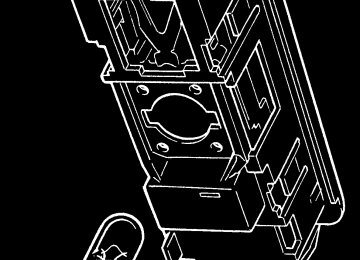
EMERGENCY RELEASE HANDLE(viewed from lid underside)
ohs148
WARNING: The maximum weight of goods which may be carried in the trunk is 110 lb (50 kg). Exceeding this limit can overload the Tires and affect the handling of the car, and result in a crash in which you or others could be killed or seriously injured. Refer also to the ‘Tires’ section in this handbook.
Child Entrapment
If a child should become trapped in the rear luggage com- partment, an emergency internal release handle is provided to facilitate their escape.
To release the latch, pull the fluorescent handle on the un-
Parents should decide if their children should be shown how
derside of the lid.
to use this feature.
80
oh_croft_InD.indd 80
20/05/2004 07:59:00
REMOVABLE ROOF CONCEPT
The Lotus Elise has been designed to exploit the pleasures of open top motoring, the better to enjoy exposure to the natu- ral environment, without the restrictions and confinement of a cockpit roof.
In order to provide some weather protection to the occupants and car interior, and allow the continued enjoyment of the car in unfavourable weather conditions, a simple hard or soft top roof may be fitted. The constant changing of loads and strains to which a car is subject to when driving on roads, and the tolerances required to allow for repeated removal and refitting of the roof, means that minor wind noise, and seepage at joints between the roof, body and doors cannot be completely sealed in certain areas. Therefore small leaks are considered normal for this model.
NOTICE: Do not take the car through an automatic car wash. The soft top may suffer damage by the brushes or suffer leaks due to the high pressure water streams directed in areas which would not apply in normal driving conditions.
WARNING: The soft or hard top roofs should be removed only whilst the car is safely parked. Do not attempt to remove the soft or hard top roof whilst the car is in motion.
81
oh_croft_InD.indd 81
20/05/2004 07:59:00
FITTING ROOF STAYS
Arrows point forward
Rear end keyway
b332
Soft Top Roof - Fitting
WARNING: Do not attempt to fit the soft top roof whilst the car is in motion. This could cause a crash in which you or others could be killed or seriously injured.
1. From its stowage bag in the rear luggage compartment, with- draw the roof assembly and support stays. Lower both door windows, or open both doors.
2. Insert the two, identical, roof support stays, with the arrows pointing forwards, into the slots above the rear window, and in the windscreen header rail. Note that the slots are keyed to allow fitment of the stays in only the correct orientation.
3. Lay the soft top roof across the centre of the roof space with
the arrows on the side rails pointing forwards.
82
oh_croft_InD.indd 82
20/05/2004 07:59:01
FITTING SIDERAIL
Spigot pin
Spring loaded pin
ohs111
4. Roll out the left hand side of the roof, and engage the spigot pin on the front and rear end of the rail, into the uppermost slot in the latch blocks at the front and rear of the roof aperture.
5. Ensure that the tensioning cables at the front and rear edges of the roof canopy are correctly located in the channels be- tween the seal and body before rotating the left hand side rail downwards. Ensure that both spring loaded pins ‘click’ into their ramped slots indicating that latching is complete. Pull up on the side rail to check security.
6. On the right hand side of the car, repeat steps (4) and (5) for
the second side rail.
NOTICE: Engaging the left hand roof side rail first, will minimise the possibility of the canopy tensioning cable adjusters causing damage to the roof seals.
WARNING: Before driving check that the roof is secure by pulling upwards on each end of both side rails. An inproperly fitted or insecure roof could cause serious injury or death to car occupants or other road users.
83
oh_croft_InD.indd 83
20/05/2004 07:59:01
RELEASING ROOF SIDE RAIL
ohs149
Soft Top - Removal
WARNING: Do not attempt to remove the soft top roof whilst the car is in motion. This could cause a crash in which you or others could be killed or seriously injured.
1. With the car stationary, open both doors or lower both door
windows.
2. On the inside face of the right hand roof side rail, locate the two latch release levers: Pull the two lever handles towards each other to release the side rail latches (press down on the side rail if necessary to relieve the load on the latch pins), and rotate the rail upwards to release the canopy tension.
3. Repeat step (2) for the left hand side rail.
NOTICE: Releasing the right hand roof side rail first, will minimise the possibility of the canopy tensioning cable adjusters causing damage to the roof seals.
4. Free the front and rear tensioning cables from the gutters be- fore carefully rolling up each side of the roof canopy towards the centre. Lift the roof assembly off the car, and pack in the roof bag.
84
oh_croft_InD.indd 84
20/05/2004 07:59:01
5. Unhook the two roof stays and pack in the roof bag. Stow the
bag in the rear luggage compartment.
NOTICE: If the roof is not fully dry, it should be stowed for no longer than 1 or 2 days before unrolling or refitting and allowing to air dry completely. Prolonged stowage of a wet or damp roof will promote rotting of the fabric.
HARD TOP ROOF
NOTICE: • The hard top roof has been designed to provide a seasonal, rather than single trip option. Some owners may prefer to entrust the fitting and removal of the hard top roof to their dealer.
• When stowing the roof off the car, care should be taken to avoid damage to the roof corners; e.g. use a suitable soft floor covering on which to stand the roof. Note that there is no provision for on-board hard top roof stowage.
• Fitment or removal of the hardtop is made considerably easier
with the assistance of a second person.
• Use only the ‘Torx’ tool supplied in the car tool kit (in the battery cover rear pocket), to tighten or release the roof fixing screws.
• The hardtop roof fixings are tethered to the roof panel to guard
against their loss.
WARNING: Take care to avoid trapping hands or fingers when fitting
or removing the hard top.
85
oh_croft_InD.indd 85
20/05/2004 07:59:01
FRONT SPIGOT BRACKET
b330
Hard Top - Fitting 1. Open both doors, and preferably with the aid of an assistant, lower the roof onto the car holding aside the loose tethered fixings to avoid their entrapment or their causing paint damage. Position the rear edge of the roof first before locating the front edge against the windscreen header rail.
2. Locate a front spigot bracket into its latch plate lower slot (lifting the roof slightly to allow this) and retain to the roof with the Torx bolt. Use only the special Torx tool supplied in the car tool kit (stowed in the battery cover pocket), and do not fully tighten at this stage.
3. Repeat step (2) for the opposite front spigot bracket.
86
oh_croft_InD.indd 86
20/05/2004 07:59:02
FITTING REAR HOOK BRACKET
h2
4. Engage a rear hook bracket with the lower tongue on its rear latch plate, and retain to the roof with the Torx bolt. Use only the special tool supplied, and do not fully tighten at this stage. Ensure that the hook is fully located onto the tongue.
5. Repeat step (4) for the opposite rear hook bracket.
6. Push the roof fully forwards before tightening the front spigot brackets using only the special Torx tool supplied. Hold each rear hook bracket in alignment whilst tightening the single fixing screw for each bracket. Do not overtighten.
87
oh_croft_InD.indd 87
20/05/2004 07:59:02
REAR CORNER COVER PANEL
7. Fit the trimmed cover panels to each rear corner of the roof, noting that the panels are handed for left and right sides. Press the panels firmly into position fully to engage the ‘Velcro’ fixing patches.
WARNING: Do not drive the car with the cover panels removed. Injury could result from contact with the roof brackets in a car collision.
88
oh_croft_InD.indd 88
20/05/2004 07:59:02
WINDSCREEN HEADER TRIM
8. Using the special tool provided, install the windscreen header cover panel by locating first with the central screw, and then by the outer screws before tightening in the same order.
WARNING:
• Do not drive the car with the trim cover panels removed. Injury could result from contact with the roof brackets in a car collision.
• Before driving check that the roof is secure by pulling upwards on each corner in turn. If any upward movement is evident, check the correct fitment of all mounting brack- ets. An insecure or incorrectly fitted roof could cause death or serious injury to other road users or a crash in which you or others could be killed or seriously injured.
89
oh_croft_InD.indd 89
20/05/2004 07:59:02
WINDSCREEN HEADER TRIM
b331
Hard Top - Removal
WARNING: Do not attempt to remove the hard top roof whilst the car is moving. Serious injury or death could result from an unsecured roof panel.
1. Open both doors.
2. Using the special tool supplied, release the three Torx screws securing the windscreen header trim panel, and remove the panel.
90
oh_croft_InD.indd 90
20/05/2004 07:59:03
FRONT CORNER SPIGOT BRACKET
b330
3. Using the special tool supplied, slacken the Torx screw se- curing each front corner spigot bracket to the roof, but do not yet remove the screws.
91
oh_croft_InD.indd 91
20/05/2004 07:59:03
REAR HOOK BRACKET
ohs149
4. Pull off the trim cover from each rear corner of the roof panel and remove the screw securing the hook bracket to the latch plate at each rear corner.
5. Remove the two front corner bracket fixing screws and lift the front edge of the roof slightly to release the front brackets from their latch plate slots.
6. With the aid of an assistant, lift the roof from the car taking care to restrain the tethered brackets to avoid damaging the paintwork.
7. If storing the roof vertically, take care to avoid damaging the
panel corners by using a protective floor covering.
92
oh_croft_InD.indd 92
20/05/2004 07:59:03
i
SERVICING AND MAINTENANCE
BODYCARE
Body Features
Lotus are among the world leaders in the field of automotive composite moulding design and manufacturing techniques. Composite materials have major advantages for specialist car bodies, and these brief notes introduce some features of the construction and service properties of automotive composite bodies.
The manufacturing process enables the thickness of com- posite mouldings to be varied in order to provide efficient structures of high strength and low weight. Composites will not corrode, so the strength of composite components is retained regardless of age, unless physical damage is sustained. On the Elise, the body construction utilises several mouldings to form a single unit for the whole of the nose and front wings, and a second unit for the whole of the rear body aft of the doors. These two moulded assemblies are fixed using threaded fasten- ers to permit easy removal for access to chassis or powertrain components, or to allow simple and economic accident repair. Other composite mouldings include the door shells, sills, front access panels, windscreen frame and rear bulkhead, some panels being bonded to the aluminium alloy chassis with an elastomeric adhesive.
Several different processes are used to manufacture the various panels depending on the functional requirements, with the main outer panels using an injection compression mould- ing technique which eliminates the ‘gelcoat’ used on the outer surface of conventionally manufactured composite panels. This process provides considerably increased resistance to surface damage from minor knocks, where a conventional composite panel would suffer cracking of the gel coat, or a steel panel be- come dented. If severe damage is caused to a composite panel where the underlying structure is broken, repairs may take the form of panel replacement, or of panel repair using techniques where new composite material is integrated with the old to result in undiminished panel strength.
oh_croft_InD.indd 93
20/05/2004 07:59:03
93
i
NOTICE: The Elise is not equipped with conventional separate shock absorbing bumpers, so extra care should be taken when parking to guard against body damage. The Lotus Elise does not offer the same kind and degree of impact resistance or energy absorption afforded by conventional U.S. bumper sys- tems. Care is also required, due to the low ground clearance, to guard against car underside damage caused by ramps, kerbs and road humps.
Paint Care
The acrylic enamel finish of the Lotus Elise is extremely resistant to all normal forms of atmospheric attack. Following the simple maintenance procedure summarised below will help retain the gloss, colour and protective properties of the paint throughout the life of the car. However, car finishes are not im- mune to damage and amongst the more common causes of deterioration are:
- Atmospheric contaminants; dust, soot, ash, and acidic or
alkaline aerosol mist can chemically attack paint.
- Abrasion; blowing sand and dust, or a dirty washing cloth. - Tree sap and insect fluids; can form a water-insoluble polymer
that adheres to the paint.
- Bird excrement; highly acidic or alkaline, they can chemically
etch the paint. Wash off immediately.
- Leaves; contain tannic acid which can stain light finishes.
Impact damage; granite chippings thrown up from poor or recently dressed road surfaces can subject the body to severe localised impact, and result in paint chips, especially around the vulnerable frontal panels. Do not follow other cars too closely in such circumstances. For optimum paintwork pro- tection, Lotus recommends the use of a self adhesive film kit which your dealer will be pleased to supply and/or fit.
- Moisture entrapment; Long term use of a non-breathable car cover can trap moisture and/or induce condensation and promote water penetration of the paint film.
Ventilation
Water lying on the paint surface for a lengthy period will even- tually penetrate the paint film. Although the effects will not be visible immediately, a deterioration in the protective properties of the paint film will ultimately result.
94
oh_croft_InD.indd 94
20/05/2004 07:59:03
i
It is not recommended to store a wet car in a poorly ventilated garage. If good ventilation cannot be provided, storage outside on a hard standing or under a carport is to be preferred.
Paintwork Polishing
Eventually some loss of gloss, and an accumulation of traffic film, will occur. At this stage, after normal washing, the appli- cation of a good quality liquid polish will restore the original lustre of the paint film.
Higher gloss of the paint finish, and added protection against contamination, can be obtained by the use of a wax polish. However, this can only be used successfully on a clean surface, from which the previous application has been removed with white spirit or a liquid polish cleaner.
Washing NOTICE: Lotus recommends hand washing of the painted bodywork. The car is a speciality sports vehicle not intended to go through an automatic car wash. Automatic car washing machines and jet wash facilities may have a detrimental effect on the paint film and the soft top. Use of automatic car washes will invalidate the terms of the Limited Warranty.
Many contaminants are water soluble and can be removed before any harm occurs by thorough washing with plenty of lukewarm water, together with a proprietary car wash additive (Household detergent and washing up liquid can contain cor- rosive salts, and will remove wax and accelerate oxidation). Frequent washing is the best safeguard against both seen and invisible contaminants.
Wash in the shade, and use a cotton chenille wash mitt or a sponge rinsed frequently to minimise the retension of dirt parti- cles in the mitt or sponge. Use a straight back and forth washing motion to avoid swirled micro scratches, and rinse thoroughly. In order to minimise degradation from road salt, the underside of the chassis should be rinsed with clean water as soon as possible after driving on treated roads. Many fuel filling stations offer pressure washing facilities ideal for this purpose, but do not use on the painted bodywork or soft top roof.
oh_croft_InD.indd 95
20/05/2004 07:59:04
95
i
Soft Top Roof 1. Careful vacuuming of the soft top before washing may be
helpful in removing excess dust and other foreign particles.
2. Wash in partial shade rather than strong sunlight. 3. Using only clean lukewarm water and a sponge (a chamois or cloth will leave lint, and a brush may abrade the threads), wash the entire soft top uniformly. Do NOT use a detergent, which may affect the waterproofing properties of the material.
4. Rinse the whole car to prevent streaking on the paintwork. 5. Remove surface water with a sponge and allow to air dry in direct sunlight. Ensure that the roof is fully dry before stow- ing, as prolonged stowage of a wet or damp roof will promote rotting of the fabric.
Keeping the soft top clean by regular washing will enhance the life and maintain the appearance of the roof, and facilitate subsequent cleaning. The use of stronger cleansers should be left to professionals experienced in handling this type of fabric as discoloration and degradation of the material may result. The application of wax finishes, dressings or preservatives may cause stains, and should be avoided. Your dealer will be able to advise on current Lotus approved soft top care products.
Windscreen Cleaning
When washing the windscreen, take care to lift the wiper blade only a small distance from the glass in order not to dam- age the wiper arm mechanism. Wash the wiper blade with clean water.
Alloy Road Wheels
It is recommended that the aluminium alloy road wheels are washed with the same preparation as is used to wash the bodywork. Use a brush having only nylon bristles. During the winter months, particularly when salt has been used on the roads for the dispersal of snow and ice, remove all the wheels, and wash thoroughly to remove all accumulated road filth from the wheels and Tires.
Be aware that on cars fitted with optional clear anodised forged alloy wheels (with 7 twin-spokes), the anodised surface finish may be attacked by some proprietary wheel cleaning products. Wash only using hot soapy water or car bodywork shampoo. Advise tire fitting companies accordingly.
96
oh_croft_InD.indd 96
20/05/2004 07:59:04
Upholstery Cleaning Cloth Trim: Normal cleaning consists of an occasional light wipe over with a cloth dampened in a mild soap and water solution; it is important that the cloth is only dampened, not soaked. Alter- natively, a proprietary upholstery cleaner may be used.
Leather Trim: The leather should be wiped over occasionally with a cloth dampened in warm soapy water. Use a mild, non-caustic toilet soap or soap flakes. Repeat the operation using a fresh cloth and water only, but avoid flooding the leather. Finish by drying and polishing with a soft dry cloth. The manufacturers of the leather do not recommend the use of any hide 'food', and prohibit the use of petrol or detergents, furniture creams and polishes.
NOTICE: Lotus cars are upholstered with premium quality leather specifically tanned and dyed for automotive use. As a natural material, leather ages in various ways and may, over time, exhibit signs of cracking, scuffing, shrinking, etc. Such wear is not an indication of a defect, but rather the natural maturing of the leather.
Seat Belts Cleaning
The seat belts may be sponged with warm water and should be allowed to air dry naturally before use. Do not use chemical cleaners and never attempt to bleach or dye the webbing.
Footwell Cleaning
Each time the car is washed, the footwell carpet mats should
be lifted and the floor surface cleaned and dried.
NOTICE: Use only correctly retained Lotus approved carpet mats in the footwells. Floor coverings made from plastic or other non-breathable materials may trap moisture and initiate surface corrosion of the footwell floors. Any damage caused by the use of incorrect mats will not be covered by your Limited Warranty.
oh_croft_InD.indd 97
20/05/2004 07:59:04
97
i
OWNER MAINTENANCE
Remember that fuel consumption and wear and tear of the car are affected considerably by the way the car is driven and maintained. Be sure to carry out the simple maintenance checks detailed below, and to have your car serviced regularly by your Lotus dealer, in order to ensure maximum safety, reliability, longevity and pleasure of ownership.
NOTICE: Failure to follow and comply with the Maintenance Schedule may invalidate the terms of the warranty.
The Lotus Elise has been designed as a road going sports car. It is recognised that owners may wish to use the car occa- sionally on closed circuit tracks to experience the car’s full range of dynamic capabilities. However, use of the car in a competitive manner, including timed runs or laps, is not endorsed by Lotus. Using the car on the track may cause a greater degree of wear and tear on parts and such wear and tear on parts and compo- nents will not be covered by your Limited Warranty.
WARNING: Any type of timed, competitive car use will invalidate warranty and require appropriate levels of expert car prepa- ration and servicing.
WARNING:
• Attempts at car servicing with inadequate knowledge, tools or equipment, could result in car damage as well as endangering you, your passenger and other road users. Consult your Lotus dealer in all cases of doubt.
• Beware of hot surfaces in the engine bay. You could be
seriously burned if you touch a hot engine part.
• Take great care not to drop flammable liquids or objects
onto a hot engine and start a fire.
• Ensure that only Lotus dealers or suitably qualified tech-
nicians work on the airbag system.
• Beware of rotating engine components; to avoid injury, guard against entrapment of tools, body parts and loose clothing.
• The front mounted electric fans can start up and cause injury even when the engine is not running. Keep tools, hands and clothing well away.
98
oh_croft_InD.indd 98
20/05/2004 07:59:04
OIL FILLER CAP
ohs131
DIPSTICK
ohs149
Engine Oil Level Check
WARNING:
if swallowed.
• Engine oil is hazardous to your health and may be fatal
• Use protective gloves to avoid contact with skin as far
as possible and wash thoroughly after any contact.
The engine oil level should be checked regularly, such as every two or three fuel stops, and the oil level maintained near the top mark on the dipstick. It is especially important to keep a check on the oil level during the car’s first 1,000 miles (1,600 km), as both the fuel and oil consumption will be prone to some variance until the engine components have bedded in.
The best time to check the level is when the oil is warm, such as during a fuel stop. Ensure that the car is parked on a level surface and that a few minutes have elapsed since stopping the engine to allow oil to drain back into the sump. If the engine is stopped before reaching normal running temperature, the oil will not drain back so readily, and the dipstick will display an artificially low reading.
Dipstick: The dipstick is identifiable by its yellow loop handle, and is located at the right hand front of the engine. Withdraw the dipstick, and wipe with a paper towel. Replace the dipstick, if necessary feeding the blade into the tube with the towel, before
oh_croft_InD.indd 99
20/05/2004 07:59:05
99
i
pressing firmly to ensure that the handle is fully seated. With- draw the dipstick again to inspect the oil level, which should lie between the two dimples on the end of the stick. The oil level should be maintained at the upper of these two marks in order to provide optimum engine protection.
Topping Up: If topping up is necessary, unscrew the oil filler cap from the left hand end of the cam cover. Add a suitable quantity of the recommended engine oil (see ‘Recommended Lubricants’) taking care not to spill any oil onto engine or electrical compo- nents; use a funnel if necessary.
The difference between high and low dipstick marks is equiv- alent to 1.6 U.S. quarts (1.5 litre). Allow several minutes for the oil to drain through to the sump before re-checking the oil level. Do NOT overfill, or lubrication will be degraded and consump- tion increased as the oil becomes aerated. Refit the filler cap, turning clockwise until secure.
Engine Oil Change
The use of high quality oil, renewed at the specified intervals, is the key to engine longevity and sustained performance. Ad- here strictly to the engine oil and filter change intervals specified in the Maintenance Schedule.
For access to the engine sump and filter, the engine bay undertray must first be removed. This is most easily achieved with the car raised on a garage hydraulic lift, or alternatively, parked over an inspection pit.
The drain plug is located at the rear of the sump, and should be removed to drain the sump immediately after a run when the oil is warm and the impurities are still held in suspension. On cars fitted with front mounted oil coolers, it is not necessary routinely to attempt to drain the cooler circuit.
100
oh_croft_InD.indd 100
20/05/2004 07:59:05
• Engine oil is hazardous to your health and may be fatal
• Take all suitable precautions to guard against scalding
WARNING:
if swallowed.
from the hot oil.
• Prolonged and repeated contact with used engine oil may cause serious skin disorders, including dermatitis and cancer.
• Use protective gloves to avoid contact with skin as far
as possible and wash thoroughly after any contact.
• Keep out of reach of children.
Allow the oil to drain completely before cleaning the drain plug, fitting a new sealing washer, and tightening securely. Refit the undertray.
Refill with the recommended lubricant (see page 153) via the oil filler on the camshaft cover, to the top mark on the dipstick, allowing several minutes for the oil to drain through to the sump before checking the level. Take care not to overfill. Refit the oil filler cap securely, and check the oil level again when the engine is fully warm (see above).
oh_croft_InD.indd 101
20/05/2004 07:59:05
101
i
SUMP DRAIN PLUG
ohs135
OIL FILTER
ohs129
Oil Filter
The canister type oil filter is vertically mounted at the front of the engine, and is accessible from beneath after removal of the engine bay undertray. The filter should be renewed along with the engine oil, at intervals specified in the Maintenance Schedule.
• Engine oil is hazardous to your health and may be fatal
• Take all suitable precautions to guard against scalding
WARNING:
if swallowed.
from the hot oil.
• Prolonged and repeated contact with used engine oil may cause serious skin disorders, including dermatitis and cancer.
• Use protective gloves to avoid contact with skin as far
as possible and wash thoroughly after any contact.
• Keep out of reach of children.
Remove the filter by turning in a counterclockwise direction, if necessary using an oil filter wrench, and dispose of safely (see ‘Used Engine Oil’).
Ensure that only a Lotus specified filter is fitted, as parts with identical outward appearance can contain different internal features. Before fitting a new filter, clean the mating face on the engine, and smear the new seal on the filter with clean oil. Add
102
oh_croft_InD.indd 102
20/05/2004 07:59:06
i
oh48e
a small amount of clean engine oil into the filter, screw onto its spigot and tighten BY HAND sufficiently to make a secure seal, typically 2/3 to 3/4 of a turn after the sealing faces have made contact. Overtightening using a filter wrench may damage the canister and/or complicate subsequent removal.
Before refitting the undertray, start the engine and check for oil leaks. Re-check the security of the filter, further tightening by hand if necessary. Check the oil level (see above) when the engine is fully warm.
Used Engine Oil
NOTICE: PROTECT THE ENVIRONMENT: Do not pollute drains, water courses or land with oil. Use only authorised waste collection facilities, including civic amenity sites and garages providing facilities for disposal of used oil and used oil filters. If in doubt, contact your local authority for advice on disposal.
Transmission Oil
The transmission should be checked for oil leaks, for the cor- rect oil level, and the oil renewed, at intervals specified in the Maintenance Schedule. To check the oil level: - A garage lift or inspection pit must be used. - Remove the engine bay undertray. - Wipe clean the area around the socket headed level plug on
the front face of the transmission end casing.
oh_croft_InD.indd 103
20/05/2004 07:59:06
103
i
Transmission filler/level plug
Drain plug
f131
- Remove the plug, and check that the oil is level with the bottom of the hole. Note that the release of oil trapped by the plug, should not be confused with an indication of correct oil level. If necessary, add only the specified lubricant (see ‘Recom- mended Lubricants’) via the level plug hole until the oil level stabilises at the bottom of the plug hole.
- Refit the level plug with a new sealing washer, and tighten
securely. Refit the undertray.
To renew transmission oil:
• Engine oil is hazardous to your health and may be fatal
• Take all suitable precautions to guard against scalding
WARNING:
if swallowed.
from the hot oil.
• Prolonged and repeated contact with used engine oil may cause serious skin disorders, including dermatitis and cancer.
• Use protective gloves to avoid contact with skin as far
as possible and wash thoroughly after any contact.
• Keep out of reach of children.
104
oh_croft_InD.indd 104
20/05/2004 07:59:06
- The hexagon headed drain plug located at the bottom of the final drive casing, should be removed immediately after a run when the oil is warm, taking suitable precautions against scalding.
- Clean the plug, fit a new sealing washer and refit securely. - Refill to the level plug hole as detailed above.
oh_croft_InD.indd 105
20/05/2004 07:59:06
105
i
Air bleed plug
Coolant header tank cap
ohs130
Cooling System
The engine cooling system uses a header tank to ensure that the system remains completely filled, and also to accommodate expansion of the coolant with increasing engine temperature. The tank is mounted at the left hand side of the engine bay, and is fitted with a 108 kPa (15 psi) pressure cap to raise the boiling point of the coolant to over 120°C (250°F).
WARNING:
• Do NOT attempt to remove the pressure cap or air bleed plug from the header tank when the engine is warm as serious scalding could result from boiling water and/or steam.
• Coolant is hazardous to your health and may be fatal
if swallowed.
• Keep coolant out of reach of children. • Coolant is hazardous to animals and may be fatal if swallowed. Clean up spilled coolant and do not leave in open containers.
The level of coolant in the translucent header tank will rise as the engine warms up, and fall as it cools down, and under normal circumstances it should not be necessary to add any coolant to the system between services. If overfilled, the excess coolant will be ejected when the engine is warm. If underfilled, overheating may result.
106
oh_croft_InD.indd 106
20/05/2004 07:59:07
i
As a precaution, every week when the engine is completely COLD, and without disturbing the filler cap, check that the level of coolant in the translucent tank is between the ‘FULL’ and ‘LOW’ marks moulded on the front of the tank. If topping up is required, wait until the coolant has fully cooled before turning the cap a quarter turn counterclockwise and allowing any remaining pressure to escape. Only then may the cap be completely unscrewed.
In order to maintain protection from freezing damage and metal corrosion, use only an approved coolant mixture (see below) to top up the tank to the ‘FULL’ mark. Refit the cap, and turn clockwise until the leg on the cap locates in the slot at the front of the tank.
NOTICE: If the cap is removed when the engine is warm, the coolant may boil and a small coolant loss may occur. The com- pletely cold header tank level should be checked at the first subsequent opportunity.
Cooling Fans: Two cooling fans are fitted below the radiator in the air intake duct. The fans are energised at high coolant tem- peratures, or when the air conditioning (if fitted) is selected. The fans will also run if certain types of engine fault are detected, and may operate during a 20 minute period following ignition switch off to prevent ‘hot soak’ boiling. An electric coolant circulation pump may also be heard running during this period.
WARNING: Keep hands, tools and clothing away from the radiator cooling fan area, as personal injury could result from the fans starting up without warning.
At service intervals, the air duct and matrices of the engine cooling radiator, a.c. condenser and oil coolers, should be checked externally for clogging by insects, leaves or other debris, and if necessary, a water jet used to clear the finning. Take care not to damage or distort the delicate finning of the radiator or the cooling performance will be degraded.
Anti-Freeze/Corrosion Inhibitor
It is most important that the correct coolant specification is used in order to inhibit boiling and protect the engine and heat
oh_croft_InD.indd 107
20/05/2004 07:59:07
107
i
exchangers from both frost damage, and metal corrosion. The Elise is factory filled with a 50% concentration of Havoline XLC Extended Life Coolant, which contains Organic Acid Technology (OAT) based corrosion inhibitors to provide long coolant change intervals combined with freedom from environmentally damaging phosphates, silicates and nitrites.
NOTICE: No other type of coolant should be mixed with this OAT coolant.
Havoline XLC may be identified by its orange colouration, and by a label around the header tank filler neck. The 50% concen- tration provides freezing protection down to -40°F (-40°C), and is recommended to be maintained throughout the life of the car. Stronger concentrations should not be used.
In an emergency, if an OAT coolant is not available, the cooling system should be topped up using water only, but the reduction in freezing protection should be recognised, and the concentration corrected promptly. In areas where the tap water is extremely hard (exceeding 250 parts per million), distilled, de-ionised or filtered rain water should be used for the water content of the coolant mix.
The effective level of ethylene glycol (anti-freeze) in the sys- tem may be measured by your dealer using a hydrometer, but in order to ensure that the required level of corrosion protection is maintained, the coolant should be renewed every 4 years.
For coolant capacity, refer to ‘Recommended Lubricants‘
and ‘Technical Data’.
NOTICE: Using an incorrect coolant mixture may result in ex- pensive damage to your engine and/or other car parts caused by overheating, freezing or corrosion effects. This damage would not be covered by your new car warranty.
Coolant Drain/Refill Procedure
The cooling system of the Lotus Elise has been carefully optimised to allow the required cooling performance using the minimum volume of coolant. This provides for high cooling sys- tem efficiency, with quick engine warm up and interior heating. When refilling the cooling system, it is vital to ensure that the correct bleeding procedure is followed, and that no air pockets remain. This operation should be entrusted to your Lotus dealer.
108
oh_croft_InD.indd 108
20/05/2004 07:59:07
WASHER RESERVOIR CAP
WIPER BLADE FITMENT
Wiper arm
Retaining tab
ohs130
ohs36a
Washer Reservoir
The windscreen washer reservoir is situated at the left hand rear of the engine bay, and should be kept topped up with clean water and a suitable proprietary solvent.
NOTICE: Do NOT use radiator antifreeze in the reservoir as this could seriously damage the paintwork and/or some plastic components.
The washer jets are mounted each side of the wiper spindle, and may, if necessary, be cleared or adjusted using a suitable pin.
Wiper Blade