- 2010 Mercedes-Benz R Class Owners Manuals
- Mercedes-Benz R Class Owners Manuals
- 2006 Mercedes-Benz R Class Owners Manuals
- Mercedes-Benz R Class Owners Manuals
- 2008 Mercedes-Benz R Class Owners Manuals
- Mercedes-Benz R Class Owners Manuals
- 2009 Mercedes-Benz R Class Owners Manuals
- Mercedes-Benz R Class Owners Manuals
- 2007 Mercedes-Benz R Class Owners Manuals
- Mercedes-Benz R Class Owners Manuals
- 2011 Mercedes-Benz R Class Owners Manuals
- Mercedes-Benz R Class Owners Manuals
- Download PDF Manual
-
Problem
The yellow ESP® warning lamp is lit while the engine is running.
Possible causes/consequences and M Solutions G Risk of accident ESP® and ESP® trailer stabilization are deactivated. ESP® will not stabilize the vehicle if it starts to skid or if a wheel starts to spin. X Reactivate ESP®.
The yellow ESP® warning lamp is lit while the engine is running.
The red SRS warning lamp is lit while the engine is running.
Exceptions: (Y page 68).
X Adapt your driving style to suit the road and weather conditions. If ESP® cannot be activated: X Have ESP® checked at a qualified specialist workshop. G Risk of accident ESP® is not available due to a malfunction. ESP® will not stabilize the vehicle if it starts to skid or if a wheel starts to spin. The brake system continues to function normally, but without the functions listed above. X Observe the additional display messages in the multifunction
display.
X Drive on carefully. X Visit a qualified specialist workshop. G Risk of injury The restraint systems are malfunctioning. The air bags or Emergency Tensioning Devices may either be triggered unintentionally or, in the event of an accident, not be triggered at all. X Drive on carefully. X Visit a qualified specialist workshop immediately.
G Warning In the event a malfunction of the SRS is indicated as outlined above, the SRS may not be operational. For your safety, we strongly recommend that you contact an authorized Mercedes-Benz Center immediately to have the system checked. Otherwise the SRS may not be activated when needed in an accident, which could result in serious or fatal injury, or it might deploy unexpectedly and unnecessarily which could also result in injury.
BA 251 USA, CA Edition A 2011; 1; 3, en-US d2sboike
2010-04-16T14:31:55+02:00 - Seite 242
Version: 3.0.3.5242 Warning and indicator lamps in the instrument cluster
Engine Problem ! (USA only) ; (Canada only) The yellow engine diagnostics warning lamp lights up while the engine is running.
! (USA only) ; (Canada only) The yellow engine diagnostics warning lamp lights up while the engine is running.
Possible causes/consequences and M Solutions There may be a malfunction, for example: Rin the engine management Rin the fuel injection system Rin the exhaust system Rin the ignition system (for vehicles with gasoline engines) The emission limit values may have been exceeded and the engine may be breaking in emergency mode. X Have the vehicle checked as soon as possible at a qualified
specialist workshop.
i In some states, you are required to visit a qualified specialist
workshop as soon as the yellow engine diagnostics warning lamp lights up due to the relevant applicable legislation. If necessary, check whether this is the case in the state you are in.
The fuel system pressure is too low. The fuel filler cap is not closed correctly or the fuel system is leaking. X Check that the fuel filler cap is correctly closed. X If the fuel filler cap is not correctly closed: close the fuel filler
X If the fuel filler cap is closed: visit a qualified specialist
cap.
workshop.
Vehicles with a diesel engine: the fuel tank has been run completely dry and the engine will not start. There is air in the fuel system (Y page 164). The fuel level has fallen below the reserve range. The fuel tank must be filled at least to the reserve fuel level to prevent impairment to the running of the engine. X Refuel at the nearest gas station.
The yellow reserve fuel warning lamp lights up while the engine is running.
BA 251 USA, CA Edition A 2011; 1; 3, en-US d2sboike
2010-04-16T14:31:55+02:00 - Seite 243
Version: 3.0.3.5Warning and indicator lamps in the instrument cluster
243
Possible causes/consequences and M Solutions G Risk of accident A warning is issued if: Ryou are approaching a vehicle in front at too great a speed RDISTRONIC has detected a stationary obstacle in your line of
travel
X Be prepared to brake immediately. X Pay careful attention to the traffic situation. You may have to
brake or take evasive action.
Possible causes/consequences and M Solutions G Risk of accident The TPMS has detected a loss of pressure in at least one of the tires. X Stop the vehicle without making any sudden steering or braking maneuvers. Pay attention to the traffic conditions as you do so. X Observe the additional display messages in the multifunction
display.
X Check the tire pressure. If necessary, correct the tire pressure
(Y page 327).
X If necessary, change a wheel (Y page 336). The TPMS is faulty. X Observe the additional display messages in the multifunction
display.
X Visit a qualified specialist workshop.
Driving systems Problem
· The red DTR distance warning lamp lights up while the vehicle is in motion. A warning tone also sounds.
Tires Problem
USA only: The yellow combination low tire pressure telltale/TPMS malfunction telltale for the TPMS is on.
USA only: The yellow combination low tire pressure telltale/TPMS malfunction telltale for the TPMS flashes for 60
seconds and then remains illuminated.G Warning Each tire, including the spare (if provided), should be checked every other week when cold and inflated to the inflation pressure recommended by the vehicle manufacturer on the Tire and Loading Information placard on the driver's door B-pillar or, if available, the tire inflation pressure label on the inside of the fuel filler flap. If your vehicle has tires of a different size than the size
BA 251 USA, CA Edition A 2011; 1; 3, en-US d2sboike
2010-04-16T14:31:55+02:00 - Seite 244
Version: 3.0.3.5244 Warning and indicator lamps in the instrument cluster
indicated on the Tire and Loading Information placard or, if available, the tire inflation pressure label, you should determine the proper tire inflation pressure for those tires. As an added safety feature, your vehicle has been equipped with a tire pressure monitoring system (TPMS) that illuminates a low tire pressure warning lamp when one or more of your tires are significantly underinflated. Accordingly, when the low tire pressure warning lamp illuminates, you should stop and check your tires as soon as possible, and inflate them to the proper pressure. Driving on a significantly underinflated tire causes the tire to overheat and can lead to tire failure. Underinflation also reduces fuel efficiency and tire tread life, and may affect the vehicle's handling and stopping ability. Please note that the TPMS is not a substitute for proper tire maintenance, and it is the driver’s responsibility to maintain correct tire pressure, even if underinflation has not reached the level to trigger illumination of the TPMS low tire pressure warning lamp. Your vehicle has also been equipped with a TPMS malfunction indicator to indicate when the system is not operating properly. The TPMS malfunction indicator is combined with the low tire pressure warning lamp. When the system detects a malfunction, the warning lamp will flash for approximately one minute and then remain continuously illuminated. This sequence will continue upon subsequent vehicle start-ups as long as the malfunction exists. When the malfunction indicator is lit, the system may not be able to detect or signal low tire pressure as intended. TPMS malfunctions may occur for a variety of reasons, including the installation of incompatible replacement or alternate tires or wheels on the vehicle that prevent the TPMS from functioning properly. Always check the TPMS malfunction warning lamp after replacing one or more tires or wheels on your vehicle to ensure that the replacement or alternate tires and wheels allow the TPMS to continue to function properly.
BA 251 USA, CA Edition A 2011; 1; 3, en-US d2sboike
2010-04-16T14:31:55+02:00 - Seite 245
Version: 3.0.3.5245
Vehicle equipment ............................ 246
Loading guidelines ............................ 246
Stowage compartments ................... 246
Stowage areas .................................. 249
Features ............................................. 260BA 251 USA, CA Edition A 2011; 1; 3, en-US d2sboike
2010-04-16T14:31:55+02:00 - Seite 246
Version: 3.0.3.5246 Stowage compartments
Vehicle equipment
i This manual describes all the standard and optional equipment of your vehicle which was available at the time of purchase. Country-specific differences are possible. Bear in mind that your vehicle may not feature all functions described here. This also refers to safety-related systems and functions.
Loading guidelines
G Warning! Always fasten items being carried as securely as possible. Use cargo tie-down rings and fastening materials appropriate for the weight and size of the load. In an accident, during hard braking or sudden maneuvers, loose items will be thrown around inside the vehicle. This can cause injury to vehicle occupants unless the items are securely fastened in the vehicle. To help avoid personal injury during a collision or sudden maneuver, exercise care when transporting cargo. Do not pile luggage or cargo higher than the seat backrests. The cargo compartment is the preferred place to carry objects. Always use cargo tie-down rings, and if so equipped, always use the cargo net when transporting cargo. Never drive a vehicle with the tailgate open. Deadly carbon monoxide (CO) gases may enter vehicle interior resulting in unconsciousness and death.
The gross vehicle weight (GVW) is the weight of the vehicle including fuel, the vehicle tool kit, spare tire, any installed accessories, vehicle occupants and luggage/cargo. The load limit and the gross vehicle weight rating (GVWR) of your vehicle must never be exceeded. The load limit and the GVWR are stated on the vehicle identification plate on
the B-pillar on the driver's side (Y page 330). Additionally, the cargo must be distributed so that the weight on each axle never exceeds the maximum gross axle weight rating (GAWR) for the front and rear axles. The data on GVWR and GAWR is stated on the vehicle identification plate on the B-pillar on the driver's side (Y page 330). Further information can be found in the "Loading the vehicle" section (Y page 330). The handling characteristics of a laden vehicle are dependent on the distribution of the load within the vehicle. For this reason, you should observe the following notes when transporting a load: RPosition heavy loads as far forwards as possible and as low down in the cargo compartment as possible.
RThe load must not protrude above the
upper edge of the seat backrests.
Ralways place the load against the rear or front seat backrests. Make sure that the seat backrests are securely locked into place.
RHook in the cargo net when loading. RAlways place the load behind unoccupied
seats if possible.
RSecure the load with sufficiently strong and wear-resistant tie down. Pad sharp edges for protection.
Stowage compartments Important safety guidelines G Warning! To help avoid personal injury during a collision or sudden maneuver, exercise care when storing objects in the vehicle. Put luggage or cargo in the cargo compartment if possible. Do not pile luggage or cargo higher than the seat backrests.
BA 251 USA, CA Edition A 2011; 1; 3, en-US d2sboike
2010-04-16T14:31:55+02:00 - Seite 247
Version: 3.0.3.5Stowage compartments
247
If so equipped, always use the cargo net when transporting cargo. The cargo net cannot secure hard or heavy objects. Parcel nets cannot secure hard or heavy objects. Keep compartment lids closed. This will help to prevent stored objects from being thrown about and injuring vehicle occupants during Rbraking Rvehicle maneuvers Ran accident
Stowage compartments in the front Glove box i Depending on the vehicle's equipment,
you will find an AUX-IN jack or a Media Interface installed in the glove box. A Media Interface is a universal interface for mobile audio equipment, e.g. for iPod®, USB devices (see separate COMAND APS operating instructions).
X To open: pull handle : and open glove box
flap ;.
X To close: fold glove box flap ; upwards
until it engages.
The glove box can only be locked and unlocked using the mechanical key.
1 Glove box unlocked 2 Glove box locked
Stowage compartments in the center console
Front stowage compartment
Rear stowage compartment X Briefly press chrome catch ; in the
direction of the arrow. Cover : swings upwards.
i In vehicles with the smoker's package, an
ashtray is installed instead of the rear stowage compartment (Y page 263).
BA 251 USA, CA Edition A 2011; 1; 3, en-US d2sboike
2010-04-16T14:31:55+02:00 - Seite 248
Version: 3.0.3.5248 Stowage compartments
Stowage compartment under the armrest The stowage compartment and the stowage tray can be opened separately. i In vehicles with the Rear Seat
Entertainment System, a DVD player is installed in the stowage compartment; see the separate operating instructions.
Stowage compartments in the rear Stowage compartments above the center vents in the 2nd row of seats Depending on the equipment in the vehicle, a control panel may be installed instead of the upper stowage compartment, e.g. if the vehicle has rear-compartment air conditioning for the 2nd and 3rd rows of seats.
X To open the stowage tray: press release button : and fold the armrest upwards.
X To open the stowage compartment:
press release button ; and fold the armrest upwards.
Stowage compartment in the center console in the 2nd row of seats
= Stowage tray ? Coin holder i The Roadside Assistance
º(Y page 269) and MB info call E(Y page 270) buttons are in the stowage tray = under the armrest.
X To open: press the release button under the armrest and fold the armrest upwards.
Stowage compartments in the 3rd row of seats There is a stowage compartment in the side trim on both sides. In vehicles with rear- compartment air conditioning (2nd and 3rd row of seats), a swiveling side air vent is installed instead of the stowage compartment.
BA 251 USA, CA Edition A 2011; 1; 3, en-US d2sboike
2010-04-16T14:31:55+02:00 - Seite 249
Version: 3.0.3.5Stowage areas
249
: Stowage compartment
Stowage areas Parcel nets G Warning! Vehicles with Occupant Classification System (OCS) Do not place objects with a combined weight of more than 4.4 lbs (2 kg) into the parcel net on the back of the front passenger seat. Otherwise, the OCS may not be able to properly approximate the occupant weight category. G Warning Parcel nets are intended for storing light- weight items only, such as road maps, mail, etc. Heavy objects, objects with sharp edges, or fragile objects may not be transported in the parcel nets. In an accident, during hard braking, or sudden maneuvers, they could be thrown around inside the vehicle and cause injury to vehicle occupants. Parcel nets cannot protect transported goods in the event of an accident.
Parcel nets are located in the front-passenger footwell and on the back of the driver's and the front-passenger seats.
Center console in the 2nd row of seats Removing the center console G Warning Remove all containers that may be stored in the cup holder in the rear center console. Otherwise, liquids could spill on the occupants and/or vehicle equipment. Hot fluids spilled on the vehicle occupants may cause serious injury. Liquids spilled on vehicle equipment may cause damage that is not covered by the Mercedes-Benz Limited Warranty.
The center console contains a stowage compartment (Y page 248) and a cup holder (Y page 260). If you are using the fully extended cargo compartment and want an even loading area (Y page 251), you must remove the center console. ! To avoid damage to the center console or
its components, close the stowage compartment before removing the center console.
i Remove all objects from the stowage
compartment (Y page 248) to reduce the weight of the center console.
X Pull release handle A.
The front part of center console : detaches from supporting base ?.
X Lift center console : upwards in the direction of arrow B and hold center console : in this position.
BA 251 USA, CA Edition A 2011; 1; 3, en-US d2sboike
2010-04-16T14:31:55+02:00 - Seite 250
Version: 3.0.3.5250 Stowage areas
X At the same time, reach into recess ;. X Lift center console : by recess ;
upwards in the direction of the arrow to release center console : from anchoring points =.
X Remove center console : from the
vehicle.
i Supporting base ? cannot be removed.
Installing the center console G Warning The rear center console must be properly attached to the rear center console base when the vehicle is in motion. The rear center console could otherwise come loose. It could be thrown around in the vehicle interior, causing injury to the vehicle occupants during: Rbraking Rvehicle maneuvers Ran accident
You can install the center console in two different positions. In the foremost position (position 1) you can extend the cargo compartment fully (Y page 251) without removing the center console. i The stowage compartment and cup
holder will only be illuminated if the center console is installed in the rear position (position 0).
X Position center console B above
supporting base =.
X Mount the retainers of center console B using anchoring points ? (position 1) or A (position 0) of basic carrier =.
X Guide the front part of center console B downwards in the direction of the arrow to supporting base =. Center console B must rest on supporting base =.
X Push the front part of center console B downwards until you hear center console B engage in securing rings : (position 1) or ; (position 0).
Enlarging the luggage compartment Important safety guidelines G Warning! When expanding the cargo volume, always fully fold the corresponding seats and, if so equipped, always use the cargo net when transporting cargo. Unless you are transporting cargo, the seat backrests must remain properly locked in the upright position. In an accident, during hard braking or sudden maneuvers, loose items will be thrown around inside the vehicle. This can cause injury to vehicle occupants unless the items are securely fastened in the vehicle. Always use the cargo tie-down rings.
BA 251 USA, CA Edition A 2011; 1; 3, en-US d2sboike
2010-04-16T14:31:55+02:00 - Seite 251
Version: 3.0.3.5Stowage areas
251
G Warning! Never drive a vehicle with the tailgate open. Deadly carbon monoxide (CO) gases may enter vehicle interior resulting in unconsciousness and death.
To enlarge the cargo compartment, the rear bench seats of the 2nd and 3rd rows of seats can be folded forwards separately. You can enlarge the cargo compartment partially (Y page 251) or fully (Y page 251).
Partially enlarging the luggage compartment (folding forward the seats in the 3rd row) X Move the head restraint of the corresponding seat down fully (Y page 102).
X Clamp the seat belt behind retainer ;. X Pull release handle : of backrest = upwards in the direction of the arrow. Backrest = is released.
X Fold backrest = slowly forwards.
Seat cushion ? is released and moves automatically to a vertical position.
X Fold backrest = forwards into a horizontal
position.
i Loop A can be used to pull the backrests
of the 3rd row of seats upright when the seats are moved into the original position (Y page 254).
Fully enlarging the luggage compartment (folding forward the seats in the 2nd and 3rd rows) G Warning! Folded second-row seats are intended to serve as a cargo volume expansion in conjunction with folded third-row seats only. Do not fold the second-row seats and allow third-row seat occupants to use folded second-row seats as a footrest while driving. Third-row seat occupants must, like all vehicle occupants, keep both feet on the floor in front of their seat. Otherwise, occupants could slide under their seat belt in a collision. If occupants slide under the seat belt, it would apply force at the abdomen or neck. That could cause serious or even fatal injuries. Do not fold the second-row seats and allow third- row seat occupants to use folded second-row seats as a table while driving. Objects placed on folded second-row seats may come loose during braking, vehicle maneuvers, or an accident and be thrown around the vehicle interior. Objects thrown around the vehicle interior may cause an accident and/or serious personal injury.
BA 251 USA, CA Edition A 2011; 1; 3, en-US d2sboike
2010-04-16T14:31:55+02:00 - Seite 252
Version: 3.0.3.5252 Stowage areas
! Make absolutely sure that you adhere to
the specified folding order when fully enlarging the cargo compartment: Rfold down the center seat in the 2nd row
of seats (7-seat vehicles)
Rfold down the outer seats in the 2nd row
of seats
Rfold down the seats in the 3rd row of
seats
You could otherwise damage the seats. Folding down the center seat in the 2nd row of seats ! Close the cup holder in the 2nd row of seats before folding down the 2nd row of seats. You could otherwise damage the seats or cup holder.
X Lower the head restraint on the center seat in the 2nd row of seats fully (Y page 102).
Armrest position X Pull release loop ? in the direction of the
arrow and hold it securely. The seat is released and folds up.
X Press seat A further down until the front
of the seat engages in the trunk floor position.
X Pull release loop : in the direction of the
arrow.
X Fold backrest ; forwards completely until
it is resting on seat cushion = (armrest position).
Trunk floor position Folding down the outer seats in the 2nd row of seats ! If you want to fold the outer seats down in the 2nd row of seats, the front seats must not be in the rearmost position. Otherwise, you could damage the front seats and outer seats in the 2nd row.
! Close the cup holder in the 2nd row of seats before folding down the 2nd row of seats. You could otherwise damage the seats or cup holder.
X Move the seat concerned in the 2nd row to
its rearmost position (Y page 103).
X Remove the center console for the 2nd row
of seats, if installed (Y page 249).
BA 251 USA, CA Edition A 2011; 1; 3, en-US d2sboike
2010-04-16T14:31:55+02:00 - Seite 253
Version: 3.0.3.5Stowage areas
253
i The center console in the 2nd row of seats can remain in place if it is installed in the foremost position (position1) (Y page 249). However, the loading surface will not be level.
X Remove the head restraint of the seat
concerned (Y page 102).
Folding down the seats in the 3rd row of seats X Push down the respective head restraints
in the 3rd row as far as they will go (Y page 102).
X Lay the head restraints on the seat cushion
of the corresponding seat.
X Relieve the pressure on backrest : and
pull release lever ; upwards in the direction of the arrow beyond the pressure point to the stop. Backrest : and the seat are unlocked.
X Fold backrest : forwards until it is resting
horizontally on the seat cushion.
X Now push backrest : down further until
seat cushion ; engages on the floor.
X Clamp the seat belt behind retainer ;. X Pull release handle : of backrest = upwards in the direction of the arrow. Backrest = is released.
X Fold backrest = slowly forwards.
Seat cushion C is released and moves automatically to a vertical position.
i Loop D can be used to pull the backrests
of the 3rd row of seats upright when the seats are moved into the original position (Y page 254).
X After it has been moved to a vertical
position automatically, fold seat cushion C further forwards until it reaches a horizontal position. In doing so, make sure that guide pin A of seat cushion C catches fully in recess ? of backrest B.
BA 251 USA, CA Edition A 2011; 1; 3, en-US d2sboike
2010-04-16T14:31:55+02:00 - Seite 254
Version: 3.0.3.5254 Stowage areas
i The seats in the 2nd row of seats must be
in the rearmost position (Y page 103).
X Fold backrest = forwards into a horizontal
position.
Resetting the seats to the driving position G Warning! Make sure Rthe seats are properly locked Rthe seat backrests are in an upright position
and are properly locked
An outboard second-row seat is properly locked only when lock status indicator : is in hinged position and red marking ; is barely visible, see "Lock status indicators (outboard second-row seats)". If a seat and seat backrest are not properly locked, the seat could move forward and the seat backrest could fold. You could slide under the seat belt during braking, vehicle maneuvers, or in an accident. If you slide under it, the belt would apply force at the abdomen or neck. That could cause serious or even fatal injuries.
! Make absolutely sure that you reset the seats to the driving position in the specified order: Rreset the seats in the 3rd row of seats Rreset the outer seats in the 2nd row of
seats
Rreset the center seat in the 2nd row of
seats (7-seat vehicles)
Resetting the seats in the 3rd row of seats
! Do not fold down the seat cushions before
moving the backrests into the upright position. The seat cover could otherwise be damaged.
X Grip loop = and pull seat backrest ; into
an upright position.
X Pull release handle ? and move
backrest ; to the desired position.
X Place seat cushion : in a vertical position. X Fold seat cushion : towards backrest ;
until it engages audibly.
Resetting the outer seats in the 2nd row of seats
X Pull release lever ; upwards beyond the
pressure point to the stop and fold backrest : upwards by about 45 ˚.
X Insert the head restraint (Y page 102). X Pull release lever ; to the pressure point
and adjust backrest : to the desired position.
BA 251 USA, CA Edition A 2011; 1; 3, en-US d2sboike
2010-04-16T14:31:55+02:00 - Seite 255
Version: 3.0.3.5X Check that the seat is correctly engaged. X Set the seat head restraint to the desired
position (Y page 102).
Lock verification indicator for the outer seats in the 2nd row of seats
Seat unlocked When the seat is unlocked, lock status indicator : is folded out and indicator area ; is clearly visible. X When the seat is unlocked, fold the
backrest back until you hear the seat engage.
Seat locked When the seat is locked, lock status indicator : is folded in and indicator area ; is barely visible.
Stowage areas
255
Resetting the center seat in the 2nd row of seats
Armrest position X Pull release loop : of seat ; in the
direction of the arrow and hold it securely. The seat is released and folds up.
X Press seat ; further down until the back of the seat engages in the armrest position. X Pull release loop : of the backrest in the direction of the arrow and hold it securely. X Fold the backrest backwards until you hear
it engage.
Securing cargos Lashing eyelets Observe the following notes on securing loads: Rsecure the load using the cargo tie down
rings.
Rdo not use elastic straps or nets to secure
a load, as these are only intended as an anti-slip protection for light loads.
Rdo not route tie downs across sharp edges
or corners.
Rpad sharp edges for protection.
BA 251 USA, CA Edition A 2011; 1; 3, en-US d2sboike
2010-04-16T14:31:55+02:00 - Seite 256
Version: 3.0.3.5256 Stowage areas
Footwell of the 2nd row of seats
Mounting hooks Only use the mounting hooks to secure items of luggage up to maximum of 9 lbs (4 kg) in weight.
There is one cargo tie-down ring : in the footwell behind the driver’s seat and one in the footwell behind the front-passenger seat. Footwell of the 3rd row of seats
Two cargo tie down rings : are located in the footwell of the 3rd row of seats. Cargo compartment
There is a mounting hook : on each of the side panels in the cargo compartment.
Luggage compartment cover Important safety guidelines ! When loading the vehicle, make sure that
you do not stack the load in the cargo compartment higher than the lower edge of the side windows. Do not place heavy objects on top of the cargo compartment cover.
The cargo compartment cover can be attached behind the 2nd or 3rd row of seats.
Extending/retracting the luggage compartment cover
There are four cargo tie down rings : in the cargo compartment.
Cargo compartment cover installed behind the 3rd row of seats
s
BA 251 USA, CA Edition A 2011; 1; 3, en-US d2sboike
2010-04-16T14:31:55+02:00 - Seite 257
Version: 3.0.3.5Stowage areas
257
if you wish to install cargo compartment cover ; behind the 2nd row of seats.
X To extend: pull the cargo compartment cover back by grab handle : and clip it into retainers ; on the left and right.
X To retract: unhook the cargo compartment cover from retainers ; on the left and right and guide it forwards by grab handle : until it is fully retracted.
Removing/installing the luggage compartment cover
Protective cap in the right-hand side panel of the 3rd row of seats X Push in the bottom of the protective cap as
indicated by the arrow. The protective cap folds out at the top. X Pull the protective cap up from the side
panel in the direction of the arrow.
Cargo compartment cover installed behind the 2nd row of seats X To remove: make sure that cargo compartment cover ; is rolled up.
X Press button :. X Move cargo compartment cover ; to the
left.
X Remove cargo compartment cover ;. X To install: extend cargo compartment
cover ; if you wish to install cargo compartment cover ; behind the 2nd row of seats (Y page 257).
! You must not install the extensions if you
wish to install the cargo compartment cover behind the 3rd row of seats. The cargo compartment cover and side panels in the cargo compartment could otherwise be damaged.
X If installed, remove the protective caps
from the side panels on the 3rd row of seats
i Stow the protective caps in a safe place. X With the handle of the cargo compartment pointing to the rear and button : facing upwards, insert cargo compartment cover ; into the recess of the side trim on the left-hand side.
X Guide cargo compartment cover ; in front
of the recess on the right.
X Press button : and insert the right-hand side section into the recess of the side trim. X Ensure that the cargo compartment cover
has engaged properly.
Extending the luggage compartment cover The cargo compartment cover is equipped with two extensions that are fastened securely to the cargo compartment cover with cords. You must extend the cargo compartment cover if you wish to install the cargo compartment cover behind the 2nd row of seats.
BA 251 USA, CA Edition A 2011; 1; 3, en-US d2sboike
2010-04-16T14:31:55+02:00 - Seite 258
Version: 3.0.3.5258 Stowage areas
occupant compartment during a collision or sudden maneuver. The cargo net cannot prevent the movement of large, heavier objects into the passenger compartment in an accident. Such items must be properly secured using the cargo tie-down rings in the cargo compartment floor. Passenger use of seats behind installed cargo net is restricted because of the footwell being taken up by the net.
When the vehicle is loaded with objects that extend beyond the seat backrests, using a cargo net is particularly important. For reasons of safety, a cargo net should always be used when transporting cargo.
Preparing the safety net The cargo net can be used in two different positions (behind the B-pillar or the C-pillar).
RThe brackets behind B-pillar : are
required for the complete cargo compartment enlargement (Y page 251). The corresponding cargo tie down rings to tighten the net are located in the footwell of the 2nd row of seats (Y page 255).
RThe brackets behind C-pillar ; are
required for the partial cargo compartment enlargement (Y page 251). The corresponding cargo tie down rings to tighten the net are located in the footwell of the 3rd row of seats (Y page 255).
X Hold extension ? in front of cargo
compartment cover ; with guide pins : pointing directly at guides =.
X Turn extension ? and cargo compartment
cover ; towards each other in the direction of the arrow. Guide pins : engage in guides =.
If the extensions are not required, they can be secured to the cargo compartment cover.
X Slide guide rail : into guide ; to the stop.
Safety net Important safety guidelines G Warning! Make sure the cargo net is properly engaged at top and bottom position and the tightening belts are securely fastened. Never use a damaged cargo net. Always use cargo net when transporting cargo. This helps to avoid personal injury from smaller objects being thrown around in the
BA 251 USA, CA Edition A 2011; 1; 3, en-US d2sboike
2010-04-16T14:31:55+02:00 - Seite 259
Version: 3.0.3.5Stowage areas
259
X Undo the two Velcro fasteners of the
safety-net stowage.
X Unroll and unfold the cargo net.
The upper and lower guide rods must engage audibly.
Attaching the safety net
X Insert belt hook : into cargo tie-down
ring ; in the direction of the arrow.
X Pull tensioning strap = by the loose end in
the direction of the arrow until the cargo net is tight.
X After driving a short distance, check the
tension of the cargo net and retighten it if necessary.
Releasing the safety net
Cargo net attached behind the C-pillar : Retainer ; Guide rod X Insert guide rod ; into retainer : in the
direction of the arrow.
X Slide guide rod ; forwards into
retainer : in the direction of the arrow.
Tightening the safety net
Seat belt reel holder behind the front seats X Pull belt adjuster : upwards in the
direction of the arrow to reduce the tension on the tensioning strap.
X Unhook belt hook ; from cargo tie-down
ring =.
Detaching and storing the safety net X Detach guide rod ; from bracket :
X Press the red button on the upper and lower
(Y page 259).
guide rods.
Seat belt reel holder behind the front seats
X Fold the cargo net and roll it up. X Close the two Velcro fasteners on the cargo
net holder.
Roof carrier Important safety guidelines G Warning! Only use the roof rack when the basic carrier bars have been completely mounted. The left
BA 251 USA, CA Edition A 2011; 1; 3, en-US d2sboike
2010-04-16T14:31:55+02:00 - Seite 260
Version: 3.0.3.5260 Features
and right roof rails are only stabilized by means of the basic carrier bars being mounted. Follow the manufacturer’s installation instructions. Otherwise, an improperly attached roof rack system or its load could become detached from the vehicle. Do not exceed the maximum roof load of 220 lb (100 kg). Take into consideration that when the roof rack is loaded, the handling characteristics are different from those when operating the vehicle without the roof rack loaded.
! Mercedes-Benz recommends that you
only use roof carriers that have been tested and approved for Mercedes-Benz vehicles. This helps to prevent damage to the vehicle. Position the cargo on the roof rack in such a way that the vehicle will not sustain damage even when it is in motion. Depending on the vehicle equipment, ensure that when the roof carrier is installed you can: Rraise the tilt/sliding sunroof fully Ropen the panorama roof with power tilt/
sliding panel fully
Ropen the tailgate fully
Fastening the roof carrier
X Fold covers : upwards. X Only secure the roof carrier to the anchorage points under covers :.
X Observe the manufacturer's installation
instructions.
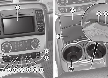
Features Cup holder Points to observe before use G Warning In order to help prevent spilling liquids on vehicle occupants and/or vehicle equipment, only use containers that fit into the cup holder. Use lids on open containers and do not fill containers to a height where the contents, especially hot liquids, could spill during braking, vehicle maneuvers, or in an accident. Liquids spilled on vehicle occupants may cause serious personal injury. Liquids spilled on vehicle equipment may cause damage not covered by the Mercedes-Benz Limited Warranty. When not in use, keep the cup holder closed. An open cup holder may cause injury to you or others when contacted during braking, vehicle maneuvers, or in an accident. Keep in mind that objects placed in the cup holder may come loose during braking, vehicle maneuvers, or in an accident and be thrown around in the vehicle interior. Objects thrown around in the vehicle interior may cause an accident and/or serious personal injury.
Cup holder in the center console In the upper center console, there is a cup holder and a removable support with a card holder
BA 251 USA, CA Edition A 2011; 1; 3, en-US d2sboike
2010-04-16T14:31:55+02:00 - Seite 261
Version: 3.0.3.5Features
261
X To install the card holder: insert lugs A
into the openings.
X Align card holder ; at the bottom and
insert into cup holder :.
Cup holder for the second row of seats below the center air vents Opening the cup holder ! Close the cup holder if you are not using it and before folding down the second row of seats.
Short wheelbase vehicles with a center console for the second row of seats do not have a cup holder below the center air vents.
X To remove the card holder: raise card
holder ; at the rear and remove.
Card holder with bottle opener Cards and car park tickets can be inserted into the slot in the center. The bottle opener is located under the card holder. It can be use to open both screw caps = and crown caps ?. i If you take out the card holder, you can
remove the rubber insert for cleaning.
X Press button ;.
Cover : opens automatically.
X Pull cover : down in the direction of the
arrow as far as it will go.
BA 251 USA, CA Edition A 2011; 1; 3, en-US d2sboike
2010-04-16T14:31:55+02:00 - Seite 262
Version: 3.0.3.5262 Features
X Pull cup holder = out to the stop in the
direction of the arrow.
Closing the cup holder X Make sure that there is no drink container
in the cup holder.
X Push cup holder = forwards into the
stowage compartment until it engages.
X Close cover :.
Cup holder in the center console
Sun visors G Warning Do not use the vanity mirror while driving. Keep the vanity mirrors in the sun visors closed while the vehicle is in motion. Reflected glare can endanger you and others.
Cup holder in the third row of seats The cup holders are located in the side trim on the left and right-hand sides.
: Mirror light ; Bracket = Vanity mirror ? Retaining clip, e.g. for a car park ticket A Mirror cover
Vanity mirror in the sun visor Mirror light : only functions if the sun visor is clipped into retainer ; and mirror cover A has been folded up.
BA 251 USA, CA Edition A 2011; 1; 3, en-US d2sboike
2010-04-16T14:31:55+02:00 - Seite 263
Version: 3.0.3.5Features
263
opened simultaneously. The roller sunblind can jump out of the retainers and spring back suddenly when driving at high speeds, e.g. when driving on the freeway. This could damage the inertia reel. Therefore, either close the side window or retract the roller sunblind before driving at high speeds.
Ashtray Ashtray in the cockpit i There is a stowage space under the
ashtray.
! The stowage space under the ashtray is
not heat resistant. Before placing lit cigarettes in the ashtray, make sure that the ashtray is properly engaged. Otherwise, the stowage space could be damaged.
Glare from the side
X Fold down sun visor :. X Pull sun visor : out of retainer =. X Swing sun visor : to the side. X Vehicles with a sliding sunroof: fold
down additional sun visor ; to the windshield.
Roller sunblinds for the rear side windows The roller sunblinds for the rear side windows are only available in the USA.
X To extend: pull the roller sunblind out by tab ; and hook it onto retainers : at the top of the window.
! Always guide the roller sunblind by hand.
Do not let it snap back suddenly as this would damage the automatic roller mechanism.
! Do not drive the vehicle with the roller sunblind hooked in and the side windows
X To open: open cover : (Y page 247). X To remove the insert: reach into the
recess on the rear of insert ;.
X Pull insert ; upwards and remove it. X To refit the insert: press insert ; into the opening from above and press it down until it engages.
Ashtray in the second row of seats Short wheelbase vehicles with a center console in the second row of seats do not have an ashtray below the center console.
BA 251 USA, CA Edition A 2011; 1; 3, en-US d2sboike
2010-04-16T14:31:55+02:00 - Seite 264
Version: 3.0.3.5264 Features
: Cover ; Insert X To open: open cover :(Y page 248). X Fold cover : down in the direction of the
arrow as far as it will go.
X To remove the insert: press insert : in
the direction of the arrow.
X Pull insert : upwards and remove it. X To re-insert the insert: replace insert :
into the opening from above.
X Push insert : down until it engages. X To close: pull cover ; upwards until it
engages in the first position.
X Swing cover ; forwards until it engages in
the second position.
Cigarette lighter G Warning When leaving the vehicle, always remove the SmartKey from the ignition lock. Always take the SmartKey with you and lock the vehicle. Do not leave children unattended in the vehicle, even if they are secured in a child restraint system, or with access to an unlocked vehicle. A child's unsupervised access to a vehicle could result in an accident and/or serious personal injury. The children could: Rinjure themselves on parts of the vehicle Rbe seriously or fatally injured through
excessive exposure to extreme heat or cold Rinjure themselves or cause an accident with
vehicle equipment that can be operated even if the SmartKey is removed from the ignition lock or removed from the vehicle, such as seat adjustment, steering wheel adjustment, or the memory function
If children open a door, they could injure other persons or get out of the vehicle and injure themselves or be injured by following traffic. Do not expose the child restraint system to direct sunlight. The child restraint system's metal parts, for example, could become very hot, and the child could be burned on these parts. G Warning Never touch the heating element or sides of the lighter; they are extremely hot. Hold the knob only. Make sure any children traveling with you do not injure themselves or start a fire with the hot cigarette lighter.
! The 12 V socket in the cigarette lighter
can be used for accessories (up to a maximum of 85 W) as long as they have the standard socket type for cigarette lighters. Note that the socket in the cigarette lighter can be damaged when connecting accessories, for example by frequent
BA 251 USA, CA Edition A 2011; 1; 3, en-US d2sboike
2010-04-16T14:31:55+02:00 - Seite 265
Version: 3.0.3.5insertion and removal or by sockets that do not fit correctly. A damaged socket can cause the cigarette lighter to stop working.
Socket in the front-passenger footwell
Features
265