- 2001 Mercedes-Benz E Class Wagon Owners Manuals
- Mercedes-Benz E Class Wagon Owners Manuals
- 2002 Mercedes-Benz E Class Wagon Owners Manuals
- Mercedes-Benz E Class Wagon Owners Manuals
- 2007 Mercedes-Benz E Class Wagon Owners Manuals
- Mercedes-Benz E Class Wagon Owners Manuals
- 2006 Mercedes-Benz E Class Wagon Owners Manuals
- Mercedes-Benz E Class Wagon Owners Manuals
- 2005 Mercedes-Benz E Class Wagon Owners Manuals
- Mercedes-Benz E Class Wagon Owners Manuals
- 2003 Mercedes-Benz E Class Wagon Owners Manuals
- Mercedes-Benz E Class Wagon Owners Manuals
- Download PDF Manual
-
your health.
i Do not place the SmartKey in the cargo compartment. You may lock yourself out.
Limiting opening height of tailgate* Vehicles with tailgate opening/closing system*: The tailgate opening height can be limited when transporting goods on a roof rack (e.g. presence of an optional MB sport lug- gage container). When activated, the tail- gate opens to approximately the height of the roof edge.
Activating 왘 Pull on the tailgate handle
(컄 page 121).
왘 Press the tailgate closing switch
(컄 page 125) for approximately 2 sec- onds. An acoustic signal sounds once. The opening height of the tailgate is limited. When you now open the tailgate it will stop at the limited height position.
123
왘 Lower tailgate using handle 1. 왘 Close tailgate with hands placed flat on
Warning!
the tailgate.
1 Strap in vehicles with folding bench
seat
왘 Pull the tailgate down from the inside of
the vehicle using strap 1.
To prevent possible personal injury, always keep hands and fingers away from the cargo compartment opening when closing the tail- gate. Be especially careful when small chil- dren are around.
When leaving the vehicle, always remove the SmartKey or SmartKey with KEYLESS-GO* from the starter switch, take it with you, and lock the vehicle. Do not leave children unat- tended in the vehicle, or with access to an unlocked vehicle. A child’s unsupervised ac- cess to a vehicle could result in an accident and/or serious personal injury.
Controls in detail Locking and unlocking
i If the vehicle was previously centrally locked, the tailgate will lock automatically after closing it. All turn signal lamps flash three times to confirm locking. Vehicles with KEYLESS-GO*: To prevent a possi- ble inadvertent lockout, the tailgate will open au- tomatically if a SmartKey with KEYLESS-GO is recognized inside the vehicle or in the cargo compartment. The vehicle is only locked when the turn signals flash three times. If you are carrying a second SmartKey with KEYLESS-GO with you, you can still lock the vehicle.
Closing tailgate from the outside manually
1 Handle
124
When leaving the vehicle, always remove the SmartKey or the SmartKey with KEYLESS-GO* from the starter switch, take it with you, and lock the vehicle. Do not leave children unattended in the vehicle. Children could open the tailgate from the in- side, which could result in an accident and/or serious personal injury.
In vehicles with tailgate opening/closing system* you can close the tailgate sepa- rately from the outside using the tailgate closing switch.
Closing the tailgate from the outside automatically*
Warning!
Monitor the closing procedure carefully to make sure no one is in danger of being in- jured. To prevent possible personal injury, always keep hands and fingers away from the cargo compartment opening when clos- ing the tailgate. Be especially careful when small children are around. To stop the clos- ing procedure, do one of the following: 앫 press button Š on the SmartKey or
SmartKey with KEYLESS-GO
앫 press or pull the tailgate opening switch
(on the driver’s door)
앫 press the tailgate closing switch 앫 press the KEYLESS-GO locking/closing* switch
앫 pull the tailgate handle
Controls in detail Locking and unlocking
Vehicles with KEYLESS-GO* 1 Tailgate closing switch 왘 Press tailgate closing switch 1 briefly.
The tailgate closes.
i If the tailgate lid comes into contact with an object while closing (e.g. luggage that has been piled too high) in the upper motion sequence, the closing procedure is stopped and the tailgate re- opens slightly.
Vehicles without KEYLESS-GO* 1 Tailgate closing switch
125
Controls in detail Locking and unlocking
Closing tailgate and locking vehicle from outside (vehicles with KEYLESS-GO*) In vehicles with tailgate opening/closing system* and KEYLESS-GO, you can close the tailgate and lock the vehicle simulta- neously from the outside using the KEYLESS-GO locking/closing switch.
1 KEYLESS-GO locking/closing switch 왘 Make sure you have the SmartKey with
KEYLESS-GO with you.
126
왘 Press switch 1 briefly.
Automatic central locking
With all doors closed: 앫 The locking knobs in the doors
move down.
앫 The tailgate starts to close auto-
matically.
앫 All turn signal lamps flash three
times to confirm locking once the tailgate has closed completely. 앫 An acoustic signal sounds three
times.
앫 The anti-theft alarm system is
armed.
i If the tailgate lid comes into contact with an object while closing (e.g. luggage that has been piled too high) in the upper motion sequence, the closing procedure is stopped and the tailgate re- opens slightly.
The doors and the tailgate automatically lock when the ignition is switched on and the wheels are turning at vehicle speeds of approximately 9 mph (15 km/h) or more. The locking knobs in the doors move down. You can open a locked door from the in- side. Open door only when conditions are safe to do so.
i The doors are designed to unlock automati- cally after an accident if the force of the impact exceeds a preset threshold. The vehicle locks au- tomatically when the ignition is switched on and the wheels are turning at vehicle speeds of ap- proximately 9 mph (15 km/h) or more. You could therefore lock yourself out when the vehicle 앫 is pushed or towed 앫 is on a test stand You can deactivate the automatic locking mode using the control system (컄 page 180).
Locking and unlocking from the inside
Warning!
When leaving the vehicle, always remove the SmartKey or SmartKey with KEYLESS-GO* from the starter switch, take it with you, and lock the vehicle. Do not leave children unat- tended in the vehicle, or with access to an unlocked vehicle. A child’s unsupervised ac- cess to a vehicle could result in an accident and/or serious personal injury.
You can lock or unlock the doors and the tailgate from inside using the central lock- ing switch. This can be useful, for example, if you want to lock the vehicle before start- ing to drive. The fuel filler flap cannot be locked or un- locked with the central locking switch.
Central locking switch 1 Unlocking 2 Locking
i You can open a locked door from inside at any time. Open door only when conditions are safe to do so. If the vehicle was previously centrally locked with the SmartKey or with KEYLESS-GO*, it will not unlock using the central locking switch.
Controls in detail Locking and unlocking
If the vehicle was previously locked with the cen- tral locking switch: 앫 and the SmartKey or SmartKey with
KEYLESS-GO* is set to factory settings, the complete vehicle is unlocked when a door is opened from the inside
앫 and the SmartKey or SmartKey with
KEYLESS-GO* is set to selective settings, only the door opened from the inside is un- locked
Locking 왘 Press lower half 2 of the central lock-
ing switch. If all doors are closed, the vehicle locks.
Unlocking 왘 Press upper half 1 of the central lock-
ing switch. The vehicle unlocks.
127
Controls in detail Seats
For more information on seat adjustment, see “Adjusting” (컄 page 41). For more information on folding the seats, see “Loading” (컄 page 266).
Front seat active head restraints
Warning!
For your protection, drive only with properly positioned head restraints.
Adjust the head restraint so that the center of the head restraint supports the back of the head at eye level. This will reduce the po- tential for injury to the head and neck in the event of an accident or similar situation.
Do not drive the vehicle without the seat head restraints. Head restraints are intend- ed to help reduce injuries during an acci- dent.
You cannot remove the active head re- straint on the driver’s and front passen- ger’s seats.
128
For removal of the active head restraints we recommend that you contact an autho- rized Mercedes-Benz Center.
i Adjust the head restraint in such a way that it is as close to the head as possible.
For information on head restraint adjust- ment, see “Seat adjustment” (컄 page 43). For information on active head restraints, see “Active head restraints” (컄 page 87).
Rear seat head restraints
Warning!
For safety reasons, always drive with the rear head restraints in the upright position when the rear seats are occupied.
Keep the area around head restraints clear of articles (e.g. clothing) to not obstruct the folding operation of the head restraints.
Warning!
For your protection, drive only with properly positioned head restraints.
Adjust head restraint so that the head re- straint supports the back of the head at eye level. This will reduce the potential for injury to the head and neck in the event of an ac- cident or similar situation.
Do not drive the vehicle without the seat head restraints. Head restraints are intend- ed to help reduce injuries during an acci- dent.
Do not interchange head restraints from front and rear seat.
Folding head restraints backward man- ually (rear outer seats only)
Placing head restraints upright
Head restraint height (rear outer seats only)
Controls in detail Seats
1 Release button 왘 Press the release button 1 and fold
the head restraints backward.
왘 Pull the head restraint forward until it
locks into position.
! Make sure the head restraints engage when placing them upright. Otherwise their protective function cannot be assured.
1 Release button Raising: 왘 Manually adjust the height of the head
restraint by pulling it upward. If the head restraint is fully retracted, push release button 1 and pull the head restraint out.
Lowering: 왘 To lower the head restraint, push
release button 1 and push down on the head restraint.
129
Controls in detail Seats
Head restraint tilt (rear outer seats only) Two different head restraint angle positions are available.
Removing and installing rear seat head restraints
Installing rear seat head restraints 왘 Insert head restraint and push it down
until it engages.
왘 Push button 1 and adjust head
restraint to desired position.
i When installing the head restraints, make sure that: 앫 The proper head restraint for each seat is in-
stalled. The bars of the head restraint de- signed for the middle rear seat are of even length and shorter than those designed for use on the outer rear seats.
앫 The head restraints engage fully.
1 Release button 왘 Press the release button 1 and tilt the head restraint to the desired position.
1 Release button
Removing rear seat head restraints 왘 Placing head restraints upright
(컄 page 129).
왘 Pull head restraint to its highest
position.
왘 Push release button 1 and pull out
head restraint.
130
Controls in detail Seats
Lumbar support
Multicontour seat*
왘 Switch on the ignition (컄 page 37).
The curvature of the front seats can be ad- justed to help enhance lower back support and seating comfort.
The multicontour seat has a movable seat cushion and inflatable air cushions built into the backrest to provide additional lum- bar and side support. The seat cushion movement, backrest cushion height and curvature can be con- tinuously varied with switches on the right side of the seat on the driver side, or the left side of the seat on the passenger side.
1 Adjustment lever 왘 Move adjustment lever 1 in direction of the arrows until you have reached a comfortable seating position.
1 Backrest side bolster 2 Backrest center 3 Backrest bottom 4 Seat cushion depth
Seat cushion depth 왘 Adjust the seat cushion depth to the
length of your upper leg using switch 4.
Backrest contour 왘 Adjust the contour of the backrest to
the desired position using æ or ç.
왘 Move the backrest support cushion to the bottom by using button 3 or to the center by using button 2.
Backrest side bolsters 왘 Adjust the side bolsters so that they
provide good lateral support using switch 1.
i If, after a period of time, the seat no longer provides the desired contour, then repeat the ad- justment procedure.
131
Controls in detail Seats
Seat heating*
The red indicator lamps in the switch show the heating level selected.
Three indicator lamps on (highest level). The seat heating automatically switches to level 2 after approxi- mately 5 minutes. Two indicator lamps on. The seat heating automatically switches to level 1 after approxi- mately 10 minutes. One indicator lamp on (lowest level). The seat heating automatically switches off after approximately 20 minutes. No indicator lamp on.
Level
off
132
Switching seat heating on 왘 Switch on the ignition (컄 page 37). 왘 Press switch 1.
Three red indicator lamps on the switch come on.
왘 Continue pressing switch 1 until de-
sired seat heating level is reached.
Switching seat heating off 왘 Press switch 1 repeatedly until all in-
dicator lamps go out.
i If one or more of the lamps on the seat heat- ing switch are flashing, there is insufficient volt- age available since too many electrical consumers are turned on. The seat heating switches off automatically. The seat heating will switch back on again auto- matically as soon as sufficient voltage is avail- able.
1 Front seat heating switch
1 Rear seat heating switch (Canada only) Depending on production date, your vehicle may not be equipped with the rear seat heating.
The blue indicator lamps on the switch show the ventilation level selected.
Seat ventilation*
Level
off
Three indicator lamps on (highest level). Two indicator lamps on. One indicator lamp on (lowest level). No indicator lamp on.
i The seat ventilation for the driver’s seat can be activated using summer opening feature (컄 page 241).
1 Seat ventilation switch 왘 Switch on the ignition (컄 page 37).
Controls in detail Seats
Switching seat ventilation on 왘 Press button 1 repeatedly until the
desired ventilation level is set. One or more blue indicator lamps on the switch show the selected ventila- tion level.
Switching seat ventilation off 왘 Press button 1 repeatedly until all in-
dicator lamps go out.
i If one or more of the lamps on the seat ven- tilation switch are flashing, there is insufficient voltage available since too many electrical con- sumers are turned on. The seat ventilation switches off automatically. The seat ventilation will switch back on again au- tomatically as soon as sufficient voltage is avail- able.
133
Controls in detail Seats
Folding bench seat in cargo compart- ment (optional on E 63 AMG)
Warning!
Folding out the folding bench seat
Make sure that the seat belt is positioned correctly on the body and is engaged in the seat belt buckle.
Damaged covers should be replaced with original covers only.
Do not leave children unattended in the ve- hicle, even when they are secured in a child restraint system.
Make sure that luggage and other objects are adequately secured. The load could oth- erwise injure someone in the event of an ac- cident, during hard braking or steering maneuvers.
1 Release handle for seat backrest 2 Release handle for seat cushion
i The folding bench seat in the cargo compart- ment is approved only for persons up to a height of 4.6 ft (1.40 m) and a maximum weight of 110 lb (50 kg). The twin roller blind must be installed when the folding bench seat is in use.
Warning!
When using the folding bench seat in the cargo compartment, the seats in front of it must be in the driving position.
Only drive when the head restraints for the folding bench seat have been properly ad- justed. The head restraints should be adjust- ed so that the back of the head is supported at approximately eye level. This can reduce a child’s risk of injury in the event of an ac- cident.
134
Controls in detail Seats
Before folding out the seat backrest, you must: 앫 fold the rear seat backrests into an up- right position and lock them into place
왘 Hook seat belts into mountings 3. 왘 Pull release handle 2 (컄 page 134) and fold seat cushion for the folding bench seat into sitting position.
Removing and installing seat cushions
i You must remove the seat cushion when you want to raise the loading floor, e.g. in the event of a flat tire.
앫 move the handle for the twin roller
왘 Press seat cushion as far down as it will
blind into the upper position
i The rear seat backrests can be adjusted to a more reclined position to make the folding bench seat more comfortable (컄 page 268). 왘 Pull release handle 1 and fold seat
backrest for the folding bench seat up- ward.
go. The backrest will then also engage properly.
왘 Fold head restraints into upright posi-
tion.
Removing
3 Mountings for seat belts
1 Seat guides 2 Seat cushion 왘 Fold seat cushion 2 upward and re-
move it from seat guides 1.
135
Controls in detail Seats
Installing
Folding back folding bench seat
왘 Insert seat cushion 2 (컄 page 135)
into seat guides 1 (컄 page 135) from behind 3 at a slight angle.
왘 Fold seat cushion 2 (컄 page 135) back into original position 4 until it engages.
1 Tab 2 Backrest 왘 Pull seat cushion upward using tab 1 and fold it back into original position until it engages.
1 Release knob 왘 Press release knob 1 and fold head
restraints down.
! To avoid damage, insert the head restraints completely into their guides and engage the seat belt buckles in their guides.
136
1 Release catch 2 Backrest 왘 Press release catch 1 and push head
restraints as far in as they will go.
왘 Fold seat backrest 2 of folding bench seat back into original position until it engages.
Controls in detail Seats
137
Controls in detail Memory function
Prior to operating the vehicle, the driver should check and adjust the seat height, seat position fore and aft, and seat back- rest angle if necessary, to ensure adequate control, reach and comfort. The head re- straint should also be adjusted for proper height. See also the section on air bags (컄 page 70) for more information on prop- er seat positioning. In addition, adjust the steering wheel to ensure adequate control, reach, operation and comfort. Both the interior and outside rear view mirrors should be adjusted for adequate rear vision. Fasten seat belts. Infants and small chil- dren should be seated in a properly se- cured restraint system that complies with U.S. Federal Motor Vehicle Safety Stan- dards 213 and 225 and Canadian Motor Vehicle Safety Standards 213 and 210.2.
138
With the memory function you can store up to three different settings. Each stored position on the driver’s side includes the following settings: 앫 Driver’s seat, backrest, head restraint
position
Each stored position on the front passenger side includes the following settings: 앫 Front passenger seat, backrest, head
restraint position
앫 Multicontour seat*: previously saved
앫 Multicontour seat*: previously saved
setting
setting
앫 Steering wheel position 앫 Exterior rear view mirror positions
Warning!
Do not activate the memory function while driving. Activating the memory function while driving could cause the driver to lose control of the vehicle.
Controls in detail Memory function
Storing positions into memory
Recalling positions from memory
왘 Adjust the seats, steering wheel and exterior rear view mirrors to the de- sired position (컄 page 41).
왘 Press memory button M. 왘 Release memory button M
(컄 page 139) and press memory posi- tion button 1, 2 or 3 (컄 page 139) with- in 3 seconds. All the settings are stored at the select- ed position.
! Do not operate the power seats using the memory button if the seat backrest is in an ex- cessively reclined position. Doing so could cause damage to front or rear seats. First move seat backrest to an upright position. 왘 Press and hold memory position
button 1, 2 or 3 (컄 page 139) until the seat, steering wheel and exterior rear view mirrors have completely moved to the stored positions.
i Releasing the memory position button stops movement to the stored positions immediately. The multicontour seat* will continue to be ad- justed.
Memory button
1, 2, 3 Memory position button 왘 Switch on the ignition (컄 page 37). or 왘 Open the respective door.
139
i If the mirror does move, repeat the above steps. After the setting is stored, you can move the mirror again.
왘 Stop the vehicle. 왘 Switch on the ignition (컄 page 37). 왘 Press button 2.
The passenger-side exterior rear view mirror is selected.
왘 Adjust the exterior rear view mirror
with button 3 so that you see the rear wheel and the road curb.
왘 Press memory button M 4. 왘 Within 3 seconds, press bottom of ad-
justment button 3. The parking position is stored if the mirror does not move.
Controls in detail Memory function
Storing exterior rear view mirror park- ing position
For easier parking, you can adjust the passenger-side exterior rear view mirror so that you can see the right rear wheel as soon as you engage reverse gear R. For information on activating the parking position, see “Activating exterior rear view mirror parking position” (컄 page 202).
1 Driver’s side exterior rear view mirror
button
2 Passenger side exterior rear view mir-
ror button
3 Adjustment button 4 Memory button M
140
왔 Lighting For information on how to switch on the headlamps and use the turn signals, see “Switching on headlamps” (컄 page 56) and see “Turn signals” (컄 page 56).
i If you drive in countries where vehicles drive on the other side of the road than the country where the vehicle is registered, you must have the headlamps modified for symmetrical low beams. Relevant information can be obtained at your authorized Mercedes-Benz Center.
i Vehicles equipped with active Bi-Xenon* headlamps: The active Bi-Xenon headlamps monitor your steering angle and driving speed, then automati- cally shift their beams to either side to better fol- low the curvature of the road ahead, increasing usable illumination over conventional head- lamps.
Exterior lamp switch
Exterior lamp switch
Controls in detail Lighting
1 ‚ Standing lamps, left (turn left two
stops)
2 ˆ Standing lamps, right (turn left
one stop)
3 M Off
Daytime running lamp mode (컄 page 143)
4 U Automatic headlamp mode
Daytime running lamp mode (컄 page 143)
5 C Parking lamps (also side marker lamps, tail lamps, license plate lamps, instrument panel lamps) 6 B Low beam headlamps or high
beam headlamps when the com- bination switch is pushed for- ward. The tail lamps, license plate lamps, side marker lamps, parking lamps and instrument panel lamps also come on.
7 ‡ Front fog lamps 8 † Rear fog lamp
141
Controls in detail Lighting
i If you hear a warning signal you have forgot- ten to switch off the headlamps before opening the driver’s door. In addition the message Switch off lights appears in the multifunction display. Switch off the headlamps.
Manual headlamp mode The low beam headlamps and the parking lamps can be switched on and off with the exterior lamp switch. 왘 Turn the exterior lamp switch to
position B.
Automatic headlamp mode The following lamps switch on and off automatically depending on the brightness of the ambient light: 앫 Low beam headlamps 앫 Tail and parking lamps 앫 License plate lamps 앫 Side marker lamps
142
Warning!
If the exterior lamp switch is set to U, 앫 the headlamps may switch off unexpect- edly when the system senses bright am- bient light, for example light from oncoming traffic.
앫 the headlamps will not be automatically
switched on under foggy conditions.
To minimize risk to you and to others, acti- vate headlamps by turning exterior lamp switch to B when driving or when traffic and/or ambient lighting conditions require you to do so.
In low ambient lighting conditions, only switch from position U to B with the vehicle at a standstill in a safe location. Switching from U to B will briefly switch off the headlamps. Doing so while driving in low ambient lighting conditions may result in an accident.
The automatic headlamp feature is only an aid to the driver. The driver is responsible for the operation of the vehicle’s lights at all times.
왘 Turn exterior lamp switch to
position U. With the SmartKey in starter switch position 1 or the KEYLESS-GO* start/stop button pressed once, only the parking lamps and the side marker lamps will switch on and off automati- cally. When the engine is running, the low beam headlamps, the tail and parking lamps, the licence plate lamps and the side marker lamps will switch on and off automatically.
i USA only: With the automatic headlamp mode activated you can switch on the high beam headlamps in low ambient lighting conditions.
Daytime running lamp mode 왘 Turn the exterior lamp switch to
position M or U. When the engine is running, the low beam headlamps are automatically switched on. In low ambient light conditions, the fol- lowing lamps will switch on additional- ly: 앫 Tail and parking lamps 앫 License plate lamps 앫 Side marker lamps
i With the daytime running lamp mode activat- ed and the engine running, you cannot switch off the low beam headlamps manually.
Canada only The daytime running lamp mode is manda- tory and therefore in a constant mode.
i With the exterior lamp switch in position M or U, you cannot switch on the high beam headlamps. The high beam flasher is available at all times. For nighttime driving turn the exterior lamp switch in position B to permit activation of the high beam headlamps.
When the engine is running, and you shift from a driving position to position N or P, the low beam headlamps will switch off with a 3 minute delay.
Controls in detail Lighting
When the engine is running, and you 앫 turn the exterior lamp switch to
position C, the parking lamps and the side marker lamps switch on addi- tionally.
앫 turn the exterior lamp switch to
position B, the manual headlamp mode has priority over the daytime run- ning lamp mode. The corresponding exterior lamps switch on (컄 page 141).
143
i Fog lamps will operate with the parking lamps and/or the low beam headlamps on. Fog lamps should only be used in conjunction with low beam headlamps. Consult your State or Province Motor Vehicle Regulations regarding permissible lamp operation.
i Fog lamps cannot be switched on with the exterior lamp switch in position U. To switch on the fog lamps, turn the exterior lamp switch to position B first.
Controls in detail Lighting
USA only By default, the daytime running lamp mode is deactivated. Activate the daytime run- ning lamp mode using the control system, see “Setting daytime running lamp mode (USA only)” (컄 page 176).
Locator lighting and night security illu- mination Locator lighting and night security illumi- nation are described in the “Control sys- tem” section, see (컄 page 177) and (컄 page 178).
i With the daytime running lamp mode activat- ed and the exterior lamp switch in position M, you cannot switch on the high beam headlamps. The high beam flasher is available at all times. For nighttime driving turn the exterior lamp switch in position B or U to permit activa- tion of the high beam headlamps.
When the engine is running, and you turn the exterior lamp switch to position C or B, the manual head- lamp mode has priority over the daytime running lamp mode. The corresponding exterior lamps switch on (컄 page 141).
Fog lamps
Warning!
In low ambient lighting or foggy conditions, only switch from position U to B with the vehicle at a standstill in a safe location. Switching from U to B will briefly switch off the headlamps. Doing so while driving in low ambient lighting conditions may result in an accident.
144
Controls in detail Lighting
Front fog lamps 왘 Switch on the low beam
headlamps B (컄 page 141).
Rear fog lamp (driver’s side only) 왘 Switch on the low beam
headlamps B (컄 page 141).
왘 Pull out the exterior lamp switch to first
왘 Pull out the exterior lamp switch to sec-
Combination switch
stop. The front fog lamps switch on. The green indicator lamp ‡ in the exterior lamp switch comes on (컄 page 141).
왘 Push in the exterior lamp switch.
The front fog lamps switch off. The green indicator lamp ‡ in the exterior lamp switch goes out.
ond stop. The front fog lamps and the rear fog lamp switch on. The yellow indicator lamp † in the exterior lamp switch comes on (컄 page 141).
왘 Push in the exterior lamp switch to first
stop. The rear fog lamp switches off. The yellow indicator lamp † in the exterior lamp switch goes out. The front fog lamps remain lit.
Combination switch 1 High beam 2 High beam flasher
145
Controls in detail Lighting
High beam 왘 Turn the exterior lamp switch to
position B (컄 page 141).
왘 Push the combination switch in direc- tion of arrow 1 to switch on the high beam. The high beam headlamp indicator lamp A in the instrument cluster comes on (컄 page 26).
왘 Pull the combination switch in direction
of arrow 2 to its original position to switch off the high beam. The high beam headlamp indicator lamp A in the instrument cluster goes out.
High beam flasher 왘 Pull the combination switch briefly in
direction of arrow 2.
146
Corner-illuminating front fog lamps*
Driving forward
The corner-illuminating front fog lamps im- prove illumination of the area in the direc- tion into which you are turning. The corner-illuminating front fog lamps will operate with the engine running and with 앫 the exterior lamp switch in position B (컄 page 141) or
앫 the exterior lamp switch in position U (컄 page 141) or
앫 the daytime running lamp mode
activated (컄 page 143).
i With the automatic headlamp mode activat- ed: The corner-illuminating front fog lamps will only come on in low ambient lighting conditions.
i If you are driving faster than 25 mph (40 km/h), the corner-illuminating function is not available.
Switching on corner-illuminating front fog lamps 왘 Switch on the left or right turn signal (컄 page 56), depending on whether you are turning left or right. The respective front fog lamp comes on and illuminates the area in the direc- tion into which you are turning.
or 왘 Turn steering wheel in desired direc-
tion. The front fog lamp on the side of your steering direction comes on.
i If you have switched on the turn signal for one side but turn the steering wheel in the oppo- site direction, the corner-illuminating front fog lamp comes on for the side indicated by the turn signal. The corner-illuminating front fog lamp remains lit for a maximum of 3 minutes. Afterward, it goes out even if the turn signal is still switched on.
If the turn signal should stay on after mak- ing the turn, the turn signal and the cor- ner-illuminating front fog lamps can be switched off by returning the combination switch to its original position.
i There may be a brief delay before the cor- ner-illuminating front fog lamps switch off.
i The corner-illuminating front fog lamps tem- porarily come on on both sides of the vehicle if you turn the steering wheel in one direction and then again in the other direction shortly thereaf- ter.
i The corner-illuminating front fog lamps will come on automatically depending on the steer- ing angle, even if you did not switch on either turn signal. If the corner-illuminating front fog lamps came on automatically, they will also go out automati- cally depending on the steering angle.
Switching off corner-illuminating front fog lamps The combination switch for the turn signal resets automatically after major steering wheel movements. This will switch off the corner-illuminating front fog lamps if they were activated by switching on the left or right turn signal.
Controls in detail Lighting
Driving in reverse
Switching on corner-illuminating front fog lamps 왘 Place the gear selector lever in
position R. The front fog lamp opposite to your steering direction comes on.
Switching off corner-illuminating front fog lamps 왘 Place the gear selector lever out of
position R. The respective front fog lamp goes out.
147
Switching on hazard warning flasher 왘 Press the hazard warning flasher
Switching off hazard warning flasher 왘 Press hazard warning flasher switch 1
switch 1. All turn signals are flashing.
i With the hazard warning flasher activated and the combination switch set for either left or right turn, only the respective left or right turn signals will operate when the ignition is switched on.
again.
i If the hazard warning flasher has been acti- vated automatically, press hazard warning flash- er switch 1 once to switch it off.
Controls in detail Lighting
Hazard warning flasher
The hazard warning flasher can be switched on at all times, even with the SmartKey removed from the starter switch or with the SmartKey with KEYLESS-GO* removed from the vehicle. The hazard warning flasher switches on automatically when an air bag deploys. The hazard warning flasher switch is locat- ed on the upper part of the center console.
1 Hazard warning flasher switch
148
Interior lighting in the front
The controls are located in the overhead control panel.
1 Left front reading lamp on/off 2 Automatic control on/off 3 Rear interior lighting on/off 4 Right front reading lamp on/off 5 Front interior lighting on/off 6 Interior lighting 7 Ambient lighting 8 Front reading lamps
! An interior lamp switched on manually does not go out automatically. Leaving an interior lamp switch in the ON posi- tion for extended periods of time with the engine turned off could result in a discharged battery.
Deactivating automatic control
i The interior lighting is factory-set to auto- matic mode. 왘 Press switch 2.
The interior lighting remains switched off in darkness, even when you: 앫 unlock the vehicle 앫 remove the SmartKey from the
starter switch
Controls in detail Lighting
앫 open a door 앫 open the tailgate
Activating automatic control 왘 Press switch 2.
The interior lighting switches on in darkness, when you: 앫 unlock the vehicle 앫 remove the SmartKey from the
starter switch
앫 open a door 앫 open the tailgate
The interior lighting switches off after a preset time (컄 page 179).
i If a door remains open, the interior lighting switches off automatically after approximately 5 minutes. An interior lamp switched on manually does not go out automatically.
149
Controls in detail Lighting
Manual control
Switching front/rear interior lighting on and off 왘 Press front/rear interior lighting
switch 5 or 3 (컄 page 149) to switch on the desired interior light.
왘 Press front/rear interior lighting
switch 5 or 3 again to switch off the respective interior light.
Switching front reading lamps on and off The front reading lamps are located in the lower edge of the interior rear view mirror. 왘 Press front reading lamp
switch 1 or 4 (컄 page 149) to switch on the desired front reading lamp.
왘 Press front reading lamp
switch 1 or 4 again to switch off the respective front reading lamp.
150
Ambient lighting You can switch the ambient lighting 7 (컄 page 149) on and off, using the “Control system” (컄 page 178).
Interior lighting in the rear
The overhead control panel is located above the rear seat bench.
1 Left rear reading lamp on/off 2 Left rear reading lamp 3 Ambient lighting switch, to brighten 4 Ambient lighting 5 Right rear reading lamp 6 Right rear reading lamp on/off 7 Ambient lighting switch, to dim 8 Rear interior lamp
Controls in detail Lighting
Door entry lamps
Cargo compartment lamps
For better orientation in the dark, the cor- responding door entry lamps will switch on in the darkness when you open a door and the automatic control is activated. The door entry lamps will switch off when the corresponding door is closed.
The cargo compartment lamps switch on if the cargo compartment is opened. If you leave the tailgate open for an extend- ed period of time, the cargo compartment lamps will switch off automatically after approximately 10 minutes.
i If you turn the SmartKey in the starter switch to position 0 and switch off the head- lamps, the door entry lamps will remain lit for ap- proximately 5 minutes.
Rear reading lamps 왘 Press rear reading lamp
switch 1 or 6 to switch on the re- spective rear reading lamp.
왘 Press rear reading lamp
switch 1 or 6 again to switch off the respective rear reading lamp.
Ambient lighting 왘 Press ambient lighting switch 3 or 7
repeatedly until ambient lighting 4 has reached the desired intensity.
You can switch the ambient lighting on and off, using the “Control system” (컄 page 178).
151
Controls in detail Instrument cluster
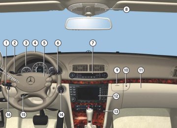
A full view illustration of the instrument cluster can be found in the “At a glance” section of this manual (컄 page 26).
1 Reset button The instrument cluster is activated when you 앫 open a door 앫 switch on the ignition (컄 page 37) 앫 press the reset button 1
앫 switch on the exterior lamps You can modify the instrument cluster set- tings in the instrument cluster submenu of the control system (컄 page 172).152
Warning!
Adjusting instrument cluster illumina- tion
No messages will be displayed if either the instrument cluster or the multifunction dis- play is inoperative.
As a result, you will not be able to see infor- mation about your driving conditions, such as speed or outside temperature, warning/ indicator lamps, malfunction/warning mes- sages or the failure of any systems. Driving characteristics may be impaired.
If you must continue to drive, please do so with added caution. Visit an authorized Mercedes-Benz Center as soon as possible.
Use the reset button 1 to adjust the illu- mination brightness for the instrument cluster.
i The instrument cluster illumination is dimmed or brightened automatically to suit am- bient light conditions. The instrument cluster illumination will also be adjusted automatically when you switch on the vehicle’s exterior lamps.
To brighten illumination 왘 Turn the reset button 1 in the instru-
ment cluster clockwise. The instrument cluster illumination will brighten.
To dim illumination 왘 Turn the reset button 1 in the instru-
ment cluster counterclockwise. The instrument cluster illumination will dim.
! Excessive coolant temperature triggers the coolant temperature warning lamp (컄 page 384) and (컄 page 413) and a warning in the multifunc- tion display (컄 page 384) and (컄 page 413). The engine should not be operated with the cool- ant temperature above 248°F (120°C). Doing so may cause serious engine damage which is not covered by the Mercedes-Benz Limited Warranty.
i During severe operating conditions, e.g. stop-and-go traffic, the coolant temperature may rise close to 248°F (120°C).
Coolant temperature indicator
Warning!
앫 Driving when your engine is overheated can cause some fluids which may have leaked into the engine compartment to catch fire. You could be seriously burned.
앫 Steam from an overheated engine can cause serious burns which can occur just by opening the engine hood. Stay away from the engine if you see or hear steam coming from it.
Turn off the engine, get out of the vehicle and do not stand near the vehicle until the engine has cooled down.
Controls in detail Instrument cluster
Trip odometer
Make sure you are viewing the trip odome- ter display (컄 page 155). 왘 If it is not displayed, press button è
or ÿ repeatedly until the trip odometer appears.
왘 Press and hold the reset button 1
(컄 page 152) until the trip odometer is reset.
Tachometer
The red marking on the tachometer de- notes excessive engine speed.
! Avoid driving at excessive engine speeds, as it may result in serious engine damage that is not covered by the Mercedes-Benz Limited Warranty.
To help protect the engine, the fuel supply is interrupted if the engine is operated within the red marking.
153
Controls in detail Instrument cluster
Outside temperature indicator
Warning!
The outside temperature indicator is not de- signed to serve as an ice-warning device and is therefore unsuitable for that purpose.
Indicated temperatures just above the freez- ing point do not guarantee that the road sur- face is free of ice. The road may still be icy, especially in wooded areas or on bridges.
The outside temperature is displayed in the instrument cluster (컄 page 26). The temperature sensor is located in the front bumper area. Due to its location, the sensor can be affected by road or engine heat during idling or slow driving. This means that the accuracy of the displayed temperature can only be verified by com- parison to a thermometer placed next to the sensor, not by comparison to external displays (e.g. bank signs etc.).
When moving the vehicle into colder ambi- ent temperatures (e.g. when leaving your garage), you will notice a delay before the lower temperature is displayed. A delay also occurs when ambient temper- atures rise. This prevents inaccurate tem- perature indications caused by heat radiated from the engine during idling or slow driving.
154
왔 Control system The control system is activated as soon as the SmartKey in the starter switch is turned to position 1 or as soon as the KEYLESS-GO start/stop button* is in position 1. The control system enables you to: 앫 call up information about your vehicle 앫 change vehicle settings For example, you can use the control sys- tem to find out when your vehicle is next due for service, to set the language for messages in the instrument cluster dis- play, and much more.
i The displays for the audio systems (radio, CD player) will appear in English, regardless of the language selected.
Controls in detail Control system
Warning!
Multifunction display
A driver’s attention to the road and traffic conditions must always be his/her primary focus when driving.
For your safety and the safety of others, se- lecting features through the multifunction steering wheel should only be done by the driver when traffic and road conditions per- mit it to be done safely.
Bear in mind that at a speed of just 30 mph (approximately 50 km/h), your vehicle is covering a distance of 44 feet (approximate- ly 14 m) every second.
The control system relays information to the multifunction display.
1 Outside temperature 2 Trip odometer 3 Automatic transmission program mode 4 Main odometer 5 Current gear selector lever position Above illustration shows the standard dis- play. For more information on menus displayed in the multifunction display, see “Menus” (컄 page 158).
155
Controls in detail Control system
Multifunction steering wheel
The displays in the multifunction display and the settings in the control system (컄 page 155) are controlled by the buttons on the multifunction steering wheel.
156
1 Multifunction display
5 Moving within a menu:
Operating the control system
2 Selecting the submenu or setting
the volume: Press button æ up/to increase ç down/to decrease
3 Telephone*: Press button s to take a call
to dial to redial
t to end a call
to reject an incoming call
4 Menu systems:
Press button è for next menu ÿ for previous menu
Press button j for next display k for previous display
Depending on the selected menu (컄 page 158), pressing the buttons on the multifunction steering wheel will alter what is shown in the multifunction display. The information available in the multifunc- tion display is arranged in menus, each containing a number of functions or sub- menus. The individual functions are then found within the relevant menu (radio or CD op- erations under AUDIO, for example). These functions serve to call up relevant informa- tion or to customize the settings for your vehicle.
Controls in detail Control system
The menus are described on the following pages.
It is helpful to think of the menus, and the functions within each menu, as being ar- ranged in a circular pattern. 앫 If you press button è or ÿ re- peatedly, you will pass through each menu one after the other.
앫 If you press button k or j re- peatedly, you will pass through each function display, one after the other, in the current menu.
In the Settings menu, instead of functions you will find a number of submenus for calling up and changing settings. For in- structions on using these submenus, see the “Settings menu” section (컄 page 169). The number of menus available in the sys- tem depends on which optional equipment is installed in your vehicle.
157
Controls in detail Control system
Menus
This is what you will see when you scroll through the menus.
The table on the next page provides an overview of the individual menus.
158
Menus, submenus and functions
Controls in detail Control system
Menu 1
Standard display (컄 page 161)s Digital speedometer
Calling up maintenance system display
1 AMG vehicles only.
Menu 2
AMG1
(컄 page 161) Engine oil temperature Vehicle supply voltageRACETIMER Overall analysis Lap analysis
Menu 3
AUDIO (컄 page 165) Selecting radio station Selecting satellite radio station* Operating CD playerMenu 4
NAV* (컄 page 167) Show route guidance in- structions, current direc- tion traveledMenu 5
Distronic* (컄 page 167) Calling up settings159
Controls in detail Control system
Menu 6
Vehicle status mes- sage memory1
(컄 page 168) Calling up vehicle mal- function, warning and system status messages stored in memoryMenu 7
SettingsMenu 8
Trip computerMenu 9
TEL*(컄 page 184) Loading phone book
Searching for name in phone book
(컄 page 169) Resetting to factory set- tings Instrument cluster sub- menu Time/Date submenu
Lighting submenu Vehicle submenu Convenience submenu
(컄 page 183) Fuel consumption statis- tics since start Fuel consumption statis- tics since the last reset Resetting fuel consump- tion statistics Distance to empty
1 The vehicle status message memory menu is only displayed if there is a message stored.
i The headings used in the menus table are designed to facilitate navigation within the sys- tem and are not necessarily identical to those shown in the control system displays.
The first function displayed in each menu will au- tomatically show you which part of the system you are in.
160
Standard display menu
AMG menu
왘 Press button k or j repeatedly to select the functions in the standard display menu.
The following functions are available:
Function Calling up digital speedometer Calling up maintenance service indicator
Page 161
365Display digital speedometer 왘 Press button k or j repeatedly until the digital speedometer appears in the multifunction display.
Controls in detail Control system
Use buttons k or j to select the fol- lowing functions in the AMG menu:
i This function is only available in AMG vehi- cles.
The main screen of the AMG menu shows you the gear currently engaged as well as the engine oil temperature. 왘 Press button è or ÿ repeatedly
until you see the AMG menu.
Function Vehicle supply voltage RACETIMER Overall analysis Lap analysis
Page 162
162
164
164i If the engine reaches the overspeed range in the manual shift program, the menu will be shown in red. In addition, you will see UP next to gear indicator 1 as a reminder to upshift.
1 Gear indicator 2 Engine oil temperature
i The engine oil temperature symbol flashes if the engine oil temperature has not yet reached 80°C. During this time, avoid driving at full en- gine speed.
161
Controls in detail Control system
Vehicle supply voltage 왘 Press button è or ÿ repeatedly
until you see the AMG menu.
왘 Press button j repeatedly until you
see the vehicle supply voltage.
1 Gear indicator 2 Vehicle supply voltage
162
RACETIMER
Warning!
The RACETIMER feature is only for use on roads and in conditions where high speed driving is permitted. Racing on public roads is prohibited under all circumstances and the driver is and must always remain re- sponsible for following posted speed limits.
The RACETIMER allows you to time and save driving stretches in hours, minutes and seconds. 왘 Press button è or ÿ repeatedly
until you see the AMG menu.
왘 Press button j repeatedly until you
see the RACETIMER.
1 Gear indicator 2 RACETIMER 3 Lap
i You can start the RACETIMER when the engine is running or the starter switch is in position 2 (컄 page 37).
i While the RACETIMER is being displayed, you cannot adjust the volume using buttons æ or ç.
Starting the RACETIMER 왘 Press button æ.
The timer starts.
Displaying intermediate time 왘 Press button ç while the timer is
running. The intermediate time is shown for 5 seconds.
Stopping the RACETIMER 왘 Press button æ.
The timer stops.
i When you stop the vehicle and turn the Smartkey to position 1 (컄 page 38) or, in vehi- cles with KEYLESS-GO*, turn off the engine and do not open the driver’s door, the RACETIMER stops timing. Timing is resumed when you switch the ignition back on (컄 page 38) or restart the engine (컄 page 52) and then press the æ button.
Controls in detail Control system
Saving lap time and starting a new lap
왘 Press button ç within the next
i You can save up to nine laps. 왘 Press button ç while the timer is
running. The intermediate time will be shown for 5 seconds.
5 seconds. The intermediate time shown will be saved as a lap time. The RACETIMER begins timing the new lap. The new lap begins to be timed as soon as the intermediate time is called up.
1 Gear indicator 2 RACETIMER 3 Best lap time 4 Lap number
163
Controls in detail Control system
Resetting current lap 왘 Press button æ while the timer is
running. The timer stops.
왘 Press button ç.
The lap time is reset to “0”.
Deleting all laps
i It is not possible to delete a single saved lap. 왘 Press button æ while the timer is
running. The timer stops.
왘 Press the reset button twice
(컄 page 27).
왘 Press button æ.
The timer starts. The saved laps are de- leted.
i When you switch off the engine, the RACETIMER will be reset to “0” after 30 seconds. All laps are deleted.
164
Overall analysis
Lap analysis
i These functions are only available if you have saved at least one lap and have stopped the RACETIMER. 왘 Press button è or ÿ repeatedly
i These functions are only available if you have saved at least two laps and have stopped the RACETIMER. 왘 Press button è or ÿ repeatedly
until you see the AMG menu.
until you see the AMG menu.
왘 Press button j repeatedly until you
왘 Press button j repeatedly until you
see the overall analysis.
see the lap analysis.
1 Overall analysis of RACETIMER 2 Overall driving time 3 Maximum speed 4 Overall distance driven 5 Average speed
1 Lap number 2 Lap time 3 Maximum speed 4 Lap length 5 Average speed during lap 왘 Press button j or k to see other
lap analyses.
i Each lap is shown in its own submenu. The fastest lap is indicated by flashing symbol 1.
AUDIO menu
The functions in the AUDIO menu operate the audio equipment which you currently have turned on. If no audio equipment is currently turned on, the message AUDIO off appears in the multifunction display. The following functions are available:
Page Function Selecting radio station 165
Selecting satellite radio station* 165
Operating CD player 166Controls in detail Control system
Selecting radio station 왘 Turn on COMAND and select radio. Re- fer to separate COMAND operating in- structions.
왘 Press button è or ÿ repeatedly
until you see the currently tuned sta- tion in the multifunction display.
Selecting satellite radio station* (USA only) The satellite radio is treated as a radio ap- plication. 왘 Select SAT radio with the correspond-
ing softkey in the radio menu.
1 SAT mode and preset number 2 Setting for station selection using
memory
3 Channel name or number 왘 Press button k or j repeatedly
until the desired channel is found.
1 Waveband setting 2 Station frequency 왘 Press button k or j repeatedly
until the desired station is found.
i You can only store new stations using the corresponding feature on the radio, see separate operating instructions. You can also operate the radio in the usual man- ner.
165
Controls in detail Control system
i Additional optional satellite radio equipment and a subscription to satellite radio service pro- vider are required for satellite radio operation. Contact an authorized Mercedes-Benz Center for details and availability for your vehicle. For more information, refer to separate COMAND operating instructions.
Operating CD player
i The COMAND system and the CD changer can play audio CDs as well as MP3-CDs. For more information on operating the CD changer refer to separate COMAND operat- ing instructions.
1 Current CD (for CD changer) 2 Current track 왘 Press button k or j repeatedly
until the desired track is selected.
1 MP3 mode 2 Current track 왘 Press button k or j repeatedly
until the desired track is selected.
i To select a CD from the CD changer maga- zine, press a number on the COMAND system key pad located in the center console.
i Level of information displayed will vary de- pending on the information contained on the MP3-CD insert in the single CD player of the COMAND system. To select a MP3-CD from the CD changer maga- zine, press a number on the COMAND system key pad located in the center console.
Selecting CD track 왘 Turn on COMAND and select CD or
CD changer. Refer to separate COMAND operating instructions.
왘 Press button è or ÿ repeatedly until the settings for the CD currently being played appear in the multifunc- tion display.
Selecting MP3-CD track 왘 Turn on COMAND and select MP3-CD. Refer to separate COMAND operating instructions.
왘 Press button è or ÿ repeatedly until the settings for the MP3-CD cur- rently being played appear in the multi- function display.
166
NAV* menu
Distronic* menu
Use the Distronic menu to display the current settings for your Distronic system. What information is shown in the multi- function display depends on whether the Distronic system is active or inactive. Please refer to the “Driving systems” sec- tion of this manual (컄 page 249) for in- structions on how to activate Distronic. 왘 Press button è or ÿ repeatedly until you see one of the following two pictures in the multifunction display.
The NAV menu contains the functions needed to operate your navigation system.