- 2013 Mercedes-Benz C Class Owners Manuals
- Mercedes-Benz C Class Owners Manuals
- 2007 Mercedes-Benz C Class Owners Manuals
- Mercedes-Benz C Class Owners Manuals
- 2000 Mercedes-Benz C Class Owners Manuals
- Mercedes-Benz C Class Owners Manuals
- 1999 Mercedes-Benz C Class Owners Manuals
- Mercedes-Benz C Class Owners Manuals
- 2010 Mercedes-Benz C Class Owners Manuals
- Mercedes-Benz C Class Owners Manuals
- 2004 Mercedes-Benz C Class Owners Manuals
- Mercedes-Benz C Class Owners Manuals
- 2005 Mercedes-Benz C Class Owners Manuals
- Mercedes-Benz C Class Owners Manuals
- 2001 Mercedes-Benz C Class Owners Manuals
- Mercedes-Benz C Class Owners Manuals
- 2003 Mercedes-Benz C Class Owners Manuals
- Mercedes-Benz C Class Owners Manuals
- 2011 Mercedes-Benz C Class Owners Manuals
- Mercedes-Benz C Class Owners Manuals
- Download PDF Manual
-
In this section you will find information on the following driving safety systems: 앫 ABS (Antilock Brake System) 앫 BAS (Brake Assist System) 앫 ESP® (Electronic Stability Program) 앫 4MATIC (Four Wheel Electronic
Traction System)
82
Warning!
ABS
The following factors increase the risk of accidents: 앫 Excessive speed, especially in turns 앫 Wet and slippery road surfaces 앫 Following another vehicle too closely The ABS, BAS, ESP®, and 4MATIC (if so equipped) cannot reduce this risk.
Always adjust your driving style to the prevailing road and weather conditions.
i In winter operation, the maximum effectiveness of the ABS, ESP®, and 4MATIC (if so equipped) is only achieved with winter tires (컄 page 308), or snow chains as required.
Warning!
Do not pump the brake pedal. Use firm, steady brake pedal pressure instead. Pump- ing the brake pedal defeats the purpose of the ABS and significantly reduces braking effectiveness.
The Antilock Brake System (ABS) regulates the brake pressure so that the wheels do not lock during braking. This allows you to maintain the ability to steer your vehicle. The ABS is functional above a speed of approximately 5 mph (8 km/h) indepen- dent of road surface conditions. On slippery road surfaces, the ABS will respond even to light brake pressure. The - indicator lamp in the instrument cluster (컄 page 24) comes on when you switch on the ignition. It goes out when the engine is running.
Braking At the instant one of the wheels is about to lock up, a slight pulsation can be felt in the brake pedal, indicating that the ABS is in the regulating mode. 왘 Keep firm and steady pressure on the
brake pedal while experiencing the pulsation.
Continuous steady brake pedal pressure yields the advantages provided by the ABS, namely braking power and ability to steer the vehicle. The pulsating brake pedal can be an indication of hazardous road conditions and functions as a reminder to take extra care while driving.
Safety and Security Driving safety systems
Emergency brake maneuver 왘 Keep continuous full pressure on the
Warning!
brake pedal.
Warning!
When the ABS is malfunctioning, the BAS and the ESP® are also switched off. The ba- sic driving and braking functions are still available
When the ABS is malfunctioning, the wheels may lock during hard braking, reducing steering capability and extending the brak- ing distance.
The ABS cannot prevent the natural laws of physics from acting on the vehicle, nor can it increase braking or steering efficiency beyond that afforded by the condition of the vehicle brakes and tires or the traction avail- able on the road surface. The ABS cannot prevent accidents, including those resulting from excessive speed in turns, following an- other vehicle too closely, or hydroplaning. Only a safe, attentive, and skillful driver can prevent accidents. The capabilities of an ABS equipped vehicle must never be exploit- ed in a reckless or dangerous manner which could jeopardize the user’s safety or the safety of others.
For more information, see the “Practical hints” section (컄 page 322).
83
Warning!
Warning!
If the BAS is malfunctioning, the brake sys- tem is still functioning normally, but without the additional brake boost available that BAS would normally provide in an emergen- cy braking maneuver. Therefore, the braking distance may increase.
The BAS cannot prevent the natural laws of physics from acting on the vehicle, nor can it increase braking efficiency beyond that afforded by the condition of the vehicle brakes and tires or the traction. The BAS cannot prevent accidents, including those resulting from excessive speed in turns, following another vehicle too closely, or hydroplaning. Only a safe, attentive, and skillful driver can prevent accidents. The capabilities of a BAS equipped vehicle must never be exploited in a reckless or danger- ous manner which could jeopardize the user’s safety or the safety of others.
Safety and Security Driving safety systems
BAS
The Brake Assist System (BAS) operates in emergency situations. If you apply the brakes very quickly, the BAS automatically provides full brake boost, thereby poten- tially reducing the braking distance. 왘 Apply continuous full braking pressure until the emergency braking situation is over. The ABS will prevent the wheels from locking.
When you release the brake pedal, the brakes function again as normal. The BAS is then deactivated.
84
Safety and Security Driving safety systems
Warning!
Warning!
Never switch off the ESP® when you see the ESP® warning lamp v flashing in the instrument cluster. In this case, proceed as follows: 앫 While driving off, apply as little throttle
as possible.
앫 While driving, ease up on the accelera-
tor.
앫 Adapt your speed and driving style to
the prevailing road conditions.
Failure to observe these guidelines could cause the vehicle to skid. The ESP® cannot prevent accidents result- ing from excessive speed.
The ESP® cannot prevent the natural laws of physics from acting on the vehicle, nor can it increase the traction afforded by the exist- ing road and tire conditions. The ESP® cannot prevent accidents, including those resulting from excessive speed in turns or hydroplaning. Only a safe, attentive, and skillful driver can prevent accidents. The capabilities of an ESP® equipped vehicle must never be exploited in a reckless or dan- gerous manner which could jeopardize the user’s safety or the safety of others.
ESP®
The Electronic Stability Program (ESP®) is operational as soon as the engine is run- ning and monitors the vehicle’s traction (force of adhesive friction between the tires and the road surface) and handling. The ESP® recognizes when a wheel is spinning or if the vehicle starts to skid. By applying the brakes to the appropriate wheel and by limiting the engine output, the ESP® works to stabilize the vehicle. The ESP® is especially useful while driving off and on wet or slippery road surfaces. The ESP® also stabilizes the vehicle during braking and steering maneuvers. The ESP® warning lamp v in the instrument cluster flashes when the ESP® is engaged. The ESP® warning lamp v in the instrument cluster comes on when you switch on the ignition. It goes out when the engine is running.
85
Safety and Security Driving safety systems
! Vehicles without 4MATIC: Because the ESP® operates automatically, the engine must be turned off (SmartKey in starter switch position 0 or 1) when 앫 the parking brake is being tested on a brake
test dynamometer
앫 the vehicle is being towed with the front axle
raised
Active braking action through the ESP® may otherwise seriously damage the brake system. For information on vehicles with 4MATIC, see “Four wheel electronic traction system (4MATIC) with the ESP® ” (컄 page 88).
i The ESP® will only function properly if you use wheels of the recommended tire size (컄 page 403). For more information, see the “Practical hints” section (컄 page 327) and (컄 page 335).
Electronic traction system The electronic traction system is a component of ESP®. The electronic traction system improves the vehicle’s ability to utilize available traction, especially under slippery road conditions by applying the brakes to a spinning wheel. When you switch off the ESP®, the electronic traction system is still enabled.
Warning!
If you are driving too fast, the electronic traction system cannot reduce the risk of an accident.
The electronic traction system cannot pre- vent the natural laws of physics from acting on the vehicle.
86
Switching off the ESP®
Warning!
The ESP® should not be switched off during normal driving other than in the circum- stances described below. Disabling of the system will reduce vehicle stability in stan- dard driving maneuvers. Do not switch off the ESP® when a Minispare wheel is mounted.
To improve the vehicle’s traction, turn off the ESP® in driving situations where it would be advantageous to have the drive wheels spin and thus cut into surfaces for better grip such as: 앫 when driving with snow chains 앫 in deep snow 앫 in sand or gravel
! Switch on the ESP® immediately if the aforementioned circumstances do not apply anymore.
When you switch off the ESP® 앫 the ESP® does not stabilize the vehicle 앫 the engine output is not limited, which
allows the drive wheels to spin and thus cut into surfaces for better grip
앫 the traction control will still apply the
brakes to a spinning wheel
앫 the ESP® continues to operate when
you are braking
앫 you cannot activate the cruise control 앫 the cruise control switches off if
currently activated
i When the ESP® is switched off and one or more drive wheels are spinning, the ESP® warn- ing lamp v in the instrument cluster flashes. However, the ESP® will then not stabilize the ve- hicle.
Safety and Security Driving safety systems
The ESP® switch is located on the center console.
Warning!
1 ESP® switch 왘 With the engine running, press ESP®
switch 1 until the ESP® warning lamp v in the instrument cluster comes on. The ESP® is switched off.
When the ESP® warning lamp v is illuminated continuously, the ESP® is switched off or is not operational due to a malfunction. Vehicle stability in standard driving maneuvers reduces.
Adapt your speed and driving to the prevail- ing road conditions and to the non-operating status of the ESP®.
! Avoid spinning of a drive wheel for an extended period with the ESP® switched off. This may cause serious damage to the drivetrain which is not covered by the Mercedes-Benz Limited Warranty.
Switching on the ESP® 왘 Press ESP® switch 1 until the ESP® warning lamp v in the instrument cluster goes out. You are now again in normal driving mode with ESP® switched on.
87
Failure to observe these guidelines could cause the vehicle to skid. The ESP® cannot prevent accidents result- ing from excessive speed.
! Do not tow with one axle raised. Otherwise the transfer case can be damaged, which is not covered by the Mercedes-Benz Limited Warranty.
! Performance testing must only be conduct- ed on a two-axle dynamometer. Otherwise the transfer case can be damaged, which is not covered by the Mercedes-Benz Limited Warranty.
! Because the ESP® operates automatically, the engine must be shut off (SmartKey in starter switch position 0 or 1) when the parking brake is being tested on a brake test dynamometer. Active braking action through the ESP® may otherwise seriously damage the front or rear axle brake system. Operational tests with the engine running can only be conducted on a two-axle dynamometer.
i At highly demanding operating conditions, the electronic traction system may temporarily switch off to prevent overheating of the drive wheel brakes. The message unavailable See Operator’s Manual will then appear in the multifunction display while the ESP® warning lamp v is flashing. The ESP® is still function- ing normally.
Safety and Security Driving safety systems
Four wheel electronic traction system (4MATIC) with the ESP®
Models with all-wheel-drive only. The 4MATIC improves vehicle’s ability to use available traction, e.g. during winter operation in mountains under snowy conditions, by applying power to all four wheels.
Warning!
If you see the ESP® warning lamp v flashing in the instrument cluster, proceed as follows: 앫 While driving off, apply as little throttle
as possible
앫 While driving, ease up on the accelera-
tor
앫 Adapt your speed and driving style to
the prevailing road conditions
88
Anti-theft alarm system*
Once the alarm system has been armed, a visual and audible alarm is triggered when someone opens 앫 a door 앫 the trunk 앫 the hood The alarm will stay on even if the activating element (e. g. a door) is immediately closed.
Safety and Security Anti-theft systems
The alarm system will also be triggered when 앫 opening the vehicle with the
mechanical key
앫 someone opens a door from the inside 앫 someone opens the trunk with the
emergency release button
i If the alarm stays on for more than 30 seconds, a call to the Response Center is ini- tiated automatically by the Tele Aid system* (컄 page 247) provided Tele Aid service was subscribed to and properly activated, and that necessary cellular service and GPS coverage are available.
왔 Anti-theft systems Immobilizer
The immobilizer prevents unauthorized persons from starting your vehicle.
Activating 왘 Remove the SmartKey from the starter
switch.
Deactivating 왘 Switch on the ignition (컄 page 32).
i Starting the engine will also deactivate the immobilizer. In case the engine cannot be started (yet the ve- hicle’s battery is charged), the system is not op- erational. Contact an authorized Mercedes-Benz Center or call 1-800-FOR-MERCedes (in the USA), or 1-800-387-0100 (in Canada).
89
Safety and Security Anti-theft systems
Arming the alarm system The indicator lamp is in the center console.
1 Indicator lamp
90
왘 Lock the vehicle with the SmartKey.
The turn signal lamps flash three times and an acoustic signal sounds three times, to indicate that the alarm sys- tem is armed. Indicator lamp 1 begins to flash after approximately 30 seconds after arming the alarm system.
i If the turn signal lamps do not flash three times, one of the following elements may not be properly closed: 앫 a door 앫 the trunk Close the respective element and lock the vehi- cle again.
Disarming the alarm system 왘 Unlock the vehicle with the SmartKey. The turn signal lamps flash once and an acoustic signal sounds once, to indicate that the alarm system is dis- armed.
i The alarm system will rearm automatically after approximately 40 seconds if neither a door nor the trunk lid was opened.
Canceling the alarm To cancel the alarm: 왘 Press the Œ or ‹ button on the
SmartKey.
or 왘 Insert the SmartKey in the starter
switch.
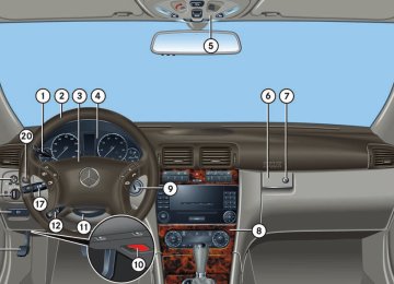
Controls in detail
Locking and unlocking Seats Memory function* Lighting Instrument cluster Control system Manual transmission Automatic transmission* Good visibility Climate control Automatic climate control Audio system Power windows Power tilt/sliding sunroof* Driving systems Loading Useful features
91
Controls in detail Locking and unlocking
In the “Controls in detail” section you will find detailed information on how to oper- ate the equipment installed on your vehi- cle. If you are already familiar with the basic functions of your vehicle, this section will be of particular interest to you. To quickly familiarize yourself with the basic functions of the vehicle, refer to the “Getting started” section of this manual. The corresponding page numbers are given at the beginning of each segment.
92
For more information on locking and unlocking, see “Getting started” (컄 page 32) and (컄 page 54).
SmartKey
Your vehicle comes supplied with two SmartKeys, each with remote control and a removable mechanical key. The locking tabs for the mechanical key portion of the two SmartKeys are a different color to help distinguish each SmartKey unit. The SmartKey provides an extended oper- ating range. To prevent theft, however, it is advisable to only unlock the vehicle when you are in close proximity to it. The SmartKey centrally locks and unlocks: 앫 the doors 앫 the trunk 앫 the fuel filler flap
SmartKey with remote control 1 ‹ Lock button 2 Š Opening button for trunk
(컄 page 95)
3 Mechanical key locking tab 4 Œ Unlock button 5 Battery check lamp 6  Panic button* (컄 page 81)
i Canada only: Only vehicles equipped with an anti-theft alarm system* have SmartKeys with integrated panic button 6.
! To prevent possible malfunction, avoid ex- posing the SmartKey to high levels of electro- magnetic radiation.
Warning!
When leaving the vehicle, always remove the SmartKey from the starter switch, take it with you, and lock the vehicle. Do not leave children unattended in the vehicle, or with access to an unlocked vehicle. It is possible for children to open a locked door from the inside, which could result in an accident and/or serious personal injury.
i USA only: This device complies with Part 15 of the FCC Rules. Operation is subject to the following two conditions: (1) This device may not cause harmful interfer-
ence, and
(2) this device must accept any interference received, including interference that may cause undesired operation.
Any unauthorized modification to this device could void the user’s authority to operate the equipment.
i Canada only: This device complies with RSS-210 of Industry Canada. Operation is subject to the following two conditions: (1) This device may not cause interference, and (2) this device must accept any interference received, including interference that may cause undesired operation of the device. Any unauthorized modification to this device could void the user’s authority to operate the equipment.
i You can also open or close the windows and the tilt/sliding sunroof* using the SmartKey (컄 page 223).
! If you can no longer lock or unlock the vehi- cle with the SmartKey, then either the batteries in the SmartKey are discharged, the SmartKey is malfunctioning or the vehicle battery is drained. 앫 Try second SmartKey. 앫 Check the batteries in the SmartKey
(컄 page 95) and replace them if necessary (컄 page 366).
앫 Use the mechanical key to unlock the driv-
er’s door (컄 page 361) and the trunk (컄 page 362).
Controls in detail Locking and unlocking
앫 Use the mechanical key to lock the driver’s
door (컄 page 362) and the trunk (컄 page 99).
앫 Have the vehicle battery and the battery con-
nections checked (컄 page 383).
If the SmartKey is malfunctioning, contact Roadside Assistance or an authorized Mercedes-Benz Center.
Factory setting
i When unlocking or locking the vehicle with the SmartKey an acoustic signal sounds. The acoustic signal is activated at the factory. If you wish to deactivate the feature, or adjust its signal volume, contact an authorized Mercedes-Benz Center.
Global unlocking 왘 Press button Œ.
앫 All turn signal lamps flash once. 앫 An acoustic signal sounds once. 앫 The locking knobs in the doors
move up.
앫 The anti-theft alarm system* is dis-
armed.
93
Controls in detail Locking and unlocking
The vehicle will lock again automatically and rearm the anti-theft alarm system* within approximately 40 seconds of un- locking if: 앫 neither door nor trunk is opened 앫 the SmartKey is not inserted in the
starter switch
앫 the central locking switch is not
activated
Global locking 왘 Press button ‹.
앫 All turn signal lamps flash three
times.
앫 An acoustic signal sounds three
times.
앫 The locking knobs in the doors
move down.
앫 The anti-theft alarm system* is
armed.
94
Selective setting If you frequently travel alone, you may wish to reprogram the SmartKey so that press- ing button Œ only unlocks the driver’s door and the fuel filler flap. 왘 Press and hold buttons Œ and ‹ simultaneously for about 5 seconds un- til battery check lamp 5 (컄 page 92) flashes twice. The SmartKey will then function as follows:
Unlocking driver’s door and fuel filler flap 왘 Press button Œ once.
앫 All turn signal lamps flash once. 앫 An acoustic signal sounds once. 앫 The locking knob in the driver’s
door moves up.
앫 The anti-theft alarm system* is dis-
armed.
Global unlocking 왘 Press button Œ twice.
앫 All turn signal lamps flash once. 앫 An acoustic signal sounds once. 앫 The locking knobs in the doors
move up.
앫 The anti-theft alarm system* is dis-
armed.
Global locking 왘 Press button ‹.
With the trunk and all doors closed: 앫 All turn signal lamps flash three
times.
앫 An acoustic signal sounds three
times.
앫 The locking knobs in the doors
move down.
앫 The anti-theft alarm system* is
armed.
Controls in detail Locking and unlocking
Checking the batteries
Loss of SmartKey or mechanical key
왘 Press button ‹ or Œ.
Battery check lamp (컄 page 92) comes on briefly to indicate that the SmartKey batteries are in order.
! If the battery check lamp does not come on briefly during check, then the SmartKey batter- ies are discharged. Replace the batteries (컄 page 366). You can obtain the required batteries at any authorized Mercedes-Benz Center.
i If the batteries are checked within signal range of the vehicle, pressing the ‹ or Œ button will lock or unlock the vehicle accordingly.
If you lose a SmartKey or mechanical key, you should do the following: 왘 Have the SmartKey deactivated by an
authorized Mercedes-Benz Center.
왘 Report the loss of the SmartKey or the
mechanical key immediately to your car insurance company.
왘 Have the mechanical lock replaced if
necessary.
Your authorized Mercedes-Benz Center will be glad to supply you with a replacement.
Restoring to factory setting 왘 Press and hold buttons Œ and ‹ simultaneously for about 5 seconds un- til Battery check lamp 5 (컄 page 92) flashes twice.
Unlocking and opening the trunk You can unlock and open the trunk separately. A minimum height clearance of 5.71 ft (1.74 m) is required to open the trunk lid. 왘 Press button Š until trunk lid
unlocks and begins to open.
! The trunk lid swings open upwards automat- ically. Always make sure there is sufficient over- head clearance.
i If the trunk does not open, it is still locked separately (컄 page 99). The trunk can also be opened from its inside in an emergency, see “Trunk emer- gency release” (컄 page 98).
95
Controls in detail Locking and unlocking
Opening the doors from the inside
You can open a locked door from the inside. Open door only when conditions are safe to do so.
1 Locking knob 2 Inside door handle
i If the vehicle has previously been locked with the SmartKey, opening a door from the inside will trigger the anti-theft alarm system*. To cancel the alarm, do one of the following: 앫 Insert the SmartKey in the starter switch. 앫 Press button Œ or ‹ on the
SmartKey.
96
Front doors 왘 Pull on door handle 2 on the
respective front door to open door. If door was locked, locking knob 1 will move up.
i If you hear a warning signal you have forgot- ten to switch off the headlamps before opening the driver’s door. In addition the message Switch off lights appears in the multifunction display. Switch off the headlamps.
Rear doors 왘 Pull up locking knob 1 on the
respective rear door to unlock door.
왘 Pull on door handle 2 on the
respective rear door to open door.
Opening the trunk
Warning!
Only drive with the trunk closed as, among other dangers such as blocked visibility, exhaust fumes may enter the vehicle interior.
You can open the trunk if the vehicle is sta- tionary. A minimum height clearance of 5.71 ft (1.74 m) is required to open the trunk lid.
! The trunk lid swings open upwards automat- ically. Always make sure there is sufficient over- head clearance.
Opening the trunk from the outside
Opening the trunk from the inside
Closing the trunk
Controls in detail Locking and unlocking
1 Handle 왘 Press and hold button Š on the
SmartKey until trunk unlocks and be- gins to open.
or 왘 Pull on handle 1.
The vehicle must be unlocked.
i If the trunk does not open, it is still locked separately (컄 page 99).
i The trunk can also be opened from its inside in an emergency, see “Trunk emergency re- lease” (컄 page 98).
1 Remote trunk opening switch 왘 Press remote trunk opening switch 1
until the trunk begins to open. The trunk opens. The indicator lamp in remote trunk opening switch 1 comes on and remains lit until the trunk is closed.
1 Handle 2 Handles 왘 Lower trunk lid by pulling firmly on
handle 1 or handles 2.
왘 Close trunk lid with hands placed flat
on the trunk lid.
i If the trunk does not open, it is still locked separately (컄 page 99).
Warning!
i The trunk can also be opened be opened us- ing button Š on the SmartKey or from its in- side in an emergency, see “Trunk emergency release” (컄 page 98).
To prevent possible personal injury, always keep hands and fingers away from the trunk opening when closing the trunk.
컄컄
97
Controls in detail Locking and unlocking
컄컄
Be especially careful when small children are around.
When leaving the vehicle, always remove the SmartKey from the starter switch, take it with you, and lock the vehicle. Do not leave children unattended in the vehicle, or with access to an unlocked vehicle. A child’s unsupervised access to a vehicle could result in an accident and/or serious personal injury.
Warning!
Only drive with the trunk closed as, among other dangers such as a blocked visibility, exhaust fumes may enter the vehicle interior.
i Do not place the SmartKey in the open trunk. You may lock yourself out.
i If the vehicle was previously centrally locked, the trunk will lock automatically after closing it. The turn signals will flash three times to confirm locking.
98
Trunk emergency release
With the emergency release button, the trunk can be opened from inside the trunk. The emergency release button is located on the inside of the trunk lid.
1 Emergency release button 왘 Briefly press emergency release
button 1. The trunk unlocks and the trunk lid opens.
! The trunk lid swings open upwards automatically.
Illumination of the emergency release button: 앫 The button flashes 30 minutes after
opening the trunk.
앫 The button flashes 60 minutes after
closing the trunk.
i The emergency release button unlocks and opens the trunk while the vehicle is standing still or in motion.
i The emergency release button does not open the trunk lid if the vehicle battery is dis- charged or disconnected.
i If the vehicle has previously been locked with the SmartKey, opening the trunk from the inside using the emergency release button will trigger the anti-theft alarm system*. To cancel the alarm, do one of the following: 앫 Press button Œ or ‹ on the
SmartKey.
앫 Insert the SmartKey in the starter switch.
왘 Turn the mechanical key clockwise to position 2 and remove the mechani- cal key in that position to lock the trunk.
The trunk remains locked even when the vehicle is centrally unlocked.
i You can only cancel the separate trunk lock- ing mode by means of the mechanical key. 왘 Insert the mechanical key in the trunk
lid lock.
왘 Turn the mechanical key counterclock- wise to neutral position 1 and remove the mechanical key in that position to unlock the trunk. You can now open the trunk (컄 page 96).
Valet locking
i To deny any unauthorized person access to the trunk, lock it separately with the mechanical key. Leave only the SmartKey less its mechani- cal key with the vehicle.
The lock is located next to the handle above the rear license plate recess.
1 Neutral position 2 Locked 왘 Close the trunk (컄 page 97). 왘 Pull the mechanical key out of the
SmartKey (컄 page 361).
왘 Insert the mechanical key in the trunk
lid lock.
Controls in detail Locking and unlocking
Automatic central locking
The doors and the trunk automatically lock when the ignition is switched on and the wheels are turning at vehicle speeds of approximately 9 mph (15 km/h) or more. You can open a locked door from the inside. Open door only when conditions are safe to do so.
i The doors unlock automatically after an ac- cident if the force of the impact exceeds a preset threshold. To prevent the vehicle door locks from locking, deactivate the automatic central locking when the vehicle 앫 is pushed or towed 앫 is on a test stand You can deactivate the automatic locking mode using the control system, see “Set- ting automatic locking” (컄 page 143).
99
Controls in detail Locking and unlocking
Locking and unlocking from the inside
You can lock or unlock the doors and the trunk from inside using the central locking or unlocking switch. This can be useful, for example, if you want to lock the vehicle before starting to drive. You cannot lock or unlock the fuel filler flap with the central locking or unlocking switch.
Warning!
When leaving the vehicle, always remove the SmartKey from the starter switch, take it with you, and lock the vehicle. Do not leave children unattended in the vehicle, or with access to an unlocked vehicle. A child’s unsupervised access to a vehicle could result in an accident and/or serious personal injury.
100
The switches are located in the center console.
1 Central locking switch 2 Central unlocking switch
i You can open a locked door from the inside. Open door only when conditions are safe to do so. If the vehicle was previously centrally locked us- ing the SmartKey, it will not unlock using the cen- tral unlocking switch 2.
If the vehicle was previously locked with the cen- tral locking switch 1
앫 while in the selective remote control mode, only the door opened from the inside is un- locked.앫 while in the global remote control mode, the complete vehicle is unlocked when a door is opened from the inside.
Locking 왘 Press central locking switch 1.
If all doors are closed, the vehicle locks.
Unlocking 왘 Press central unlocking switch 2.
The vehicle unlocks.
Controls in detail Seats
You cannot remove the active head re- straints on the driver’s and front passen- ger’s seat. For removal of the active head restraints we recommend that you contact an autho- rized Mercedes-Benz Center.
i Adjust the head restraint in such a way that it is as close to the head as possible.
For information on head restraint adjustment, see “Seats” (컄 page 34). For information on active head restraints, see “Active head restraint” (컄 page 73).
Rear seat head restraints
Warning!
For safety reasons, always drive with the rear head restraints in the upright position when the rear seats are occupied.
Keep the area around head restraints clear of articles (e.g. clothing) to not obstruct the folding operation of the head restraints.
왔 Seats For information on seat adjustment, see “Adjusting” (컄 page 34).
Front seat active head restraints
Warning!
For your protection, drive only with properly positioned head restraints.
Adjust the head restraint so that it is as close to the head as possible and the center of the head restraint supports the back of the head at eye level. This will reduce the po- tential for injury to the head and neck in the event of an accident or similar situation.
101
Controls in detail Seats
Head restraint height (rear outer seats)
1 Release button
Warning!
For your protection, drive only with properly positioned head restraints.
Adjust head restraint so that the head re- straint supports the back of the head at eye level. This will reduce the potential for injury to the head and neck in the event of an ac- cident or similar situation.
102
Do not drive the vehicle without the seat head restraints. Head restraints are intended to help reduce injuries during an accident.
Folding head restraints back with release button The rear seat head restraints can be folded backward for increased visibility.
i Adjust the head restraint in such a way that it is as close to the head as possible.
Raising 왘 Manually adjust the height of the head
restraint by pulling it upward. If the head restraint is fully retracted, push release button 1 and pull the head restraint up.
Lowering 왘 To lower the head restraint, push
release button 1 and push down on the head restraint.
1 Release button 왘 Push release button 1.
The head restraint will fold backward.
i You can also fold the rear outer seat head restraints back using the switch in the center console.
Folding head restraints back with switch in the center console
Placing head restraints upright
1 Switch for rear seat head restraints 왘 Start the engine (컄 page 46). 왘 Press switch 1.
The rear seat head restraints will fold backward.
왘 Pull the head restraint forward until it
locks into position.
Warning!
Make sure the head restraints engage when placing them upright. Otherwise their protective function cannot be assured.
Controls in detail Seats
Head restraint tilt (rear outer seats) Two different head restraint angle positions are available: 왘 Press the release button (컄 page 102)
and tilt the head restraint to the desired position.
i Adjust the head restraint in such a way that it is as close to the head as possible.
103
Controls in detail Seats
Removing and installing rear seat head restraints (rear outer seats)
i The rear center seat head restraint cannot be removed.
Warning!
For your protection, drive only with properly positioned head restraints.
Adjust head restraint so that the head re- straint supports the back of the head at eye level. This will reduce the potential for injury to the head and neck in the event of an ac- cident or similar situation.
Do not drive the vehicle without the seat head restraints. Head restraints are intend- ed to help reduce injuries during an acci- dent.
Do not interchange head restraints from front and rear seat.
104
Installing rear seat head restraints 왘 Insert head restraint and push it down
until it engages.
왘 Push release button 1 and adjust head restraint to desired position.
i Adjust the head restraint in such a way that it is as close to the head as possible.
1 Release button
Removing rear seat head restraints 왘 Fold back head restraint (컄 page 102). 왘 Pull head restraint to its highest
position.
왘 Push release button 1 and pull out
head restraint.
Controls in detail Seats
Lumbar support
Multicontour seats* (Canada only)
왘 Switch on the ignition (컄 page 32).
The curvature of the front seats can be ad- justed to help enhance lower back support and seating comfort.
This driver’s multicontour seat has a mov- able seat cushion and inflatable air cush- ions built into the backrest to provide additional lumbar and side support. The seat cushion movement, backrest cushion height and curvature can be continuously varied with switches on the side of the seat after switching on ignition.
1 Adjustment lever 왘 Move adjustment lever 1 in direction
of arrows until you have reached a comfortable seating position.
1 Seat cushion depth 2 Backrest bottom 3 Backrest center 4 Backrest side bolster adjustment
Seat cushion depth 왘 Adjust the seat cushion depth to the
length of your upper leg using switch 1.
Backrest contour 왘 Adjust the contour of the backrest to the desired position using switches 2 and 3.
Backrest side bolsters 왘 Adjust the backrest side bolsters so
that they provide good lateral support using switch 4.
i If, after a period of time, the seat no longer provides the desired contour, then repeat the ad- justment procedure.
105
Controls in detail Seats
Seat heating*
Both switches for the front seats are locat- ed in the center console. The red indicator lamps in the switch come on to show heat- ing level you have selected.
1 Seat heating switch 2 Indicator lamps 왘 Switch on the ignition (컄 page 32).
106
Level
off
Three indicator lamps on (highest level). After approximately 5 minutes, seat heating is automatically switched to level 2. Two indicator lamps on. After approximately 10 minutes, seat heating is automatically switched to level 1. One indicator lamp on (lowest level). After approximately 20 minutes, seat heating is automatically switched off. No indicator lamp on.
Switching on seat heating 왘 Press switch 1 once.
Three red indicator lamps 2 in the switch come on.
왘 Continue pressing switch 1 until
desired seat heating level is reached.
Switching off seat heating 왘 Press switch 1 repeatedly until all
indicator lamps 2 go out.
i If one or more of the indicator lamps 2 on the seat heating switch are flashing, there is in- sufficient voltage due to too many electrical con- sumers are turned on. The seat heating switches off automatically. The seat heating will switch back on again auto- matically as soon as sufficient voltage is avail- able.
Controls in detail Memory function*
The following settings are stored for the front passenger seat when using the but- tons (if so equipped depending on vehicle equipment configuration) on the passen- ger door: 앫 Front passenger seat, backrest and
head restraint position
왔 Memory function* Prior to operating the vehicle, the driver should check and adjust the seat height, seat position fore and aft, and seat back- rest angle if necessary, to ensure adequate control, reach and comfort. The head re- straint should also be adjusted for proper height. See also the section on air bags (컄 page 59) for proper seat positioning. In addition, adjust the steering wheel to ensure adequate control, reach, operation and comfort. Both the interior and exterior rear view mirrors should be adjusted for adequate rear vision. Fasten seat belts. Infants and small chil- dren should be seated in a properly se- cured restraint system that complies with U.S. Federal Motor Vehicle Safety Standards 213 and 225 and Canadian Motor Vehicle Safety Standards 213 and 210.2.
With the memory function you can store up to three different settings. The following settings are stored for the driver’s seat when using the buttons on the driver’s door: 앫 Driver’s seat, backrest and head
restraint position
앫 Steering wheel position 앫 Exterior rear view mirrors
Warning!
Do not activate the memory function while driving. Activating the memory function while driving could cause the driver to lose control of the vehicle.
107
Storing positions into memory
Recalling positions from memory
왘 Adjust the seat, steering wheel and
exterior rear view mirrors to the desired position (컄 page 34).
왘 Turn memory position switch 2 to the
desired memory position. 왘 Press memory button 1. 왘 Release memory button 1 and press
memory position switch 2 within 3 seconds. All settings are stored to the selected position.
! Do not operate the power seats using the memory button if the seat backrest is in an ex- cessively reclined position. Doing so could cause damage to front or rear seats. 왘 Turn memory position switch 2 to the
desired memory position.
왘 Press and hold memory position
switch 2 until the seat, steering wheel and exterior rear view mirrors have completely moved to the stored positions.
i Releasing the memory position switch stops movement to the stored positions immediately.
Controls in detail Memory function*
The memory button and memory position switch are located on the door.
1 Memory button 2 Memory position switch 왘 Switch on the ignition (컄 page 32). or 왘 Open the respective door.
108
Exterior lamp switch
왔 Lighting For information on how to switch on the headlamps and use the turn signals, see “Switching on headlamps” (컄 page 50) and “Turn signals” (컄 page 50).
i If you drive in countries where vehicles drive on the other side of the road than the country where the vehicle is registered, you must have the headlamps modified for symmetrical low beams. Relevant information can be obtained at your authorized Mercedes-Benz Center.
Exterior lamp switch M Off
Daytime running lamp mode (컄 page 111)
U Automatic headlamp mode
Daytime running lamp mode (컄 page 111)
C Parking lamps (also tail lamps,
license plate lamps, side marker lamps, instrument panel lamps)
Controls in detail Lighting
B Low beam headlamps or high beam headlamps when the combination switch is pushed forward. The tail lamps, license plate lamps, side marker lamps, parking lamps and instrument panel lamps also come on.
ˆ Standing lamps, right (turn left one
stop)
‚ Standing lamps, left (turn left two
stops)
‡ Indicator lamp for front fog lamps † Indicator lamp for rear fog lamp
i If you hear a warning signal you have forgotten to switch off the headlamps before opening the driver’s door. In addition the message Switch off lights appears in the multifunction display. Switch off the headlamps.
109
Controls in detail Lighting
Manual headlamp mode The low beam headlamps and the parking lamps can be switched on and off with the exterior lamp switch. 왘 Turn the exterior lamp switch to
position B.
Automatic headlamp mode The following lamps switch on and off automatically depending on the brightness of the ambient light: 앫 Low beam headlamps 앫 Tail and parking lamps 앫 License plate lamps 앫 Side marker lamps
110
Warning!
If the exterior lamp switch is set to U, 앫 the headlamps may switch off
unexpectedly when the system senses bright ambient light, for example light from oncoming traffic.
앫 the headlamps will not be automatically
switched on under foggy conditions.
To minimize risk to you and to others, activate headlamps by turning exterior lamp switch to B when driving or when traffic and/or ambient lighting conditions require you to do so.
In low ambient lighting conditions, only switch from position U to B with the vehicle at a standstill in a safe location. Switching from U to B will briefly switch off the headlamps. Doing so while driving in low ambient lighting conditions may result in an accident.
The automatic headlamp feature is only an aid to the driver. The driver is responsible for the operation of the vehicle’s lights at all times.
왘 Turn the exterior lamp switch to
position U. With the SmartKey in starter switch position 1, only the parking lamps and the side marker lamps will switch on and off automatically. When the engine is running, the low beam headlamps, the tail and parking lamps, the license plate lamps, and the side marker lamps will switch on and off automatically.
i USA only: With the automatic headlamp mode activated you can switch on the high beam headlamps in low ambient lighting conditions.
Daytime running lamp mode 왘 Turn the exterior lamp switch to
position M or U. When the engine is running, the low beam headlamps are switched on. In low ambient light conditions, the following lamps will switch on additionally: 앫 Tail and parking lamps 앫 License plate lamps 앫 Side marker lamps
i With the daytime running lamp mode activated and the engine running, you cannot switch off the low beam headlamps manually.
Canada only: The daytime running lamp mode is mandatory and therefore in a constant mode.
i With the exterior lamp switch in position M or U, you cannot switch on the high beam headlamps. The high beam flasher is available at all times. For nighttime driving turn the exterior lamp switch to position B to permit activation of the high beam headlamps.
Vehicles with automatic transmission*: When the engine is running, and you shift from a driving position to position N or P, the low beam headlamps will switch off with a three-minute delay. When the engine is running, and you 앫 turn the exterior lamp switch to
position C, the parking lamps and the side marker lamps switch on additionally.
앫 turn the exterior lamp switch to
position B, the manual headlamp mode has priority over the daytime running lamp mode. The corresponding exterior lamps switch on (컄 page 109).
Controls in detail Lighting
USA only: By default, the daytime running lamp mode is deactivated. Activate the daytime running lamp mode using the control system, see “Setting daytime running lamp mode (USA only)” (컄 page 139).
i With the daytime running lamp mode activated and the exterior lamp switch in position M, you cannot switch on the high beam headlamps. The high beam flasher is available at all times. For nighttime driving turn the exterior lamp switch to position B or U to permit activation of the high beam headlamps.
When the engine is running, and you turn the exterior lamp switch to position C or B, the manual headlamp mode has priority over the daytime running lamp mode. The corresponding exterior lamps switch on (컄 page 109).
111
Controls in detail Lighting
Locator lighting and night security illumination The locator lighting and the night security illumination are described in the “Control system” section, see “Setting locator light- ing” (컄 page 140) and “Setting night secu- rity illumination” (컄 page 141).
Fog lamps
Warning!
In low ambient lighting or foggy conditions, only switch from position U to B with the vehicle at a standstill in a safe location. Switching from U to B will briefly switch off the headlamps. Doing so while driving in low ambient lighting conditions may result in an accident.
112
i Fog lamps will operate with the parking lamps and/or the low beam headlamps on. Fog lamps should only be used in conjunction with low beam headlamps. Consult your State or Province Motor Vehicle Regulations regarding permissible lamp operation.
i Fog lamps cannot be switched on with the exterior lamp switch in position U. To switch on the fog lamps, turn the exterior lamp switch to position B first.
Front fog lamps 왘 Switch on the low beam
headlamps B (컄 page 109).
왘 Pull out the exterior lamp switch to first
stop. The front fog lamps switch on. The green indicator lamp ‡ in the exterior lamp switch comes on (컄 page 109).
왘 Push in the exterior lamp switch.
The front fog lamps switch off. The green indicator lamp ‡ in the exterior lamp switch goes out.
Rear fog lamp (driver’s side only) 왘 Switch on the low beam
headlamps B (컄 page 109).
왘 Pull out the exterior lamp switch to
second stop. The front fog lamps and the rear fog lamp switch on. The yellow indicator lamp † in the exterior lamp switch comes on (컄 page 109).
왘 Push in the exterior lamp switch to first
stop. The rear fog lamp switches off. The yellow indicator lamp † in the exterior lamp switch goes out. The front fog lamps remain lit.
Combination switch
왘 Pull the combination switch in direction
of arrow 2 to its original position to switch off the high beam. The high beam headlamp indicator lamp A in the instrument cluster goes out.
High beam flasher 왘 Pull the combination switch briefly in
direction of arrow 2.
Corner-illuminating front fog lamps* (C 230 (Canada only), C 280, C 350 and models with 4MATIC: with Bi-Xenon* headlamps)
The corner-illuminating front fog lamps improve illumination of the area in the direction into which you are turning.
Combination switch 1 High beam 2 High beam flasher
High beam 왘 Turn the exterior lamp switch to
position B (컄 page 109).
왘 Push the combination switch in
direction of arrow 1 to switch on the high beam. The high beam headlamp indicator lamp A in the instrument cluster comes on (컄 page 24).
Controls in detail Lighting
The corner-illuminating front fog lamps will operate with the engine running and with 앫 the exterior lamp switch in position B (컄 page 109) or
앫 the exterior lamp switch in position U (컄 page 109) or
앫 the daytime running lamp mode
activated (컄 page 111)
i With the automatic headlamp mode activat- ed: The corner-illuminating front fog lamps will only come on in low ambient lighting conditions.
i If you are driving faster than 25 mph (40 km/h) or have the front fog lamps switched on, the corner-illuminating front fog lamps function is not available.
113
Controls in detail Lighting
Driving forward
Switching on corner-illuminating front fog lamps 왘 Switch on the left or right turn signal (컄 page 50), depending on whether you are turning left or right. The respective front fog lamp comes on and illuminates the area in the direction into which you are turning.
or 왘 Turning steering wheel in desired
direction. The front fog lamp on the side of your steering direction comes on.
114
i If you have switched on the turn signal for one side but turn the steering wheel in the opposite direction, the corner-illuminating front fog lamp comes on for the side indicated by the turn signal. The corner-illuminating front fog lamp remains lit for a maximum of three minutes. Afterward, it goes out even if the turn signal is still switched on.
i The corner-illuminating front fog lamps tem- porarily come on, on both sides of the vehicle if you turn the steering wheel in one direction and then again in the other direction shortly thereaf- ter.
i The corner-illuminating front fog lamps will come on automatically depending on the steering angle, even if you did not switch on either turn signal. If the corner-illuminating front fog lamps came on automatically, they will also go out automatically depending on the steering angle.
Switching off corner-illuminating front fog lamps The combination switch for the turn signal resets automatically after major steering wheel movements. This will switch off the corner-illuminating front fog lamps if they were activated by switching on the left or right turn signal. If the turn signal should stay on after making the turn, the turn signal and the corner-illuminating front fog lamp can be switched off by returning the combination switch to its original position.
i There may be a brief delay before the corner-illuminating front fog lamps switch off.
Driving in reverse
Hazard warning flasher
Switching on corner-illuminating front fog lamps 왘 Place the gear selector lever (manual
transmission: gearshift lever) in position R. The corner-illuminating front fog lamp opposite to your steering direction comes on.
The hazard warning flasher can be switched on at all times, even with the SmartKey removed from the starter switch. The hazard warning flasher switches on automatically when an air bag deploys. The hazard warning flasher switch is located on the center console.
Switching off corner-illuminating front fog lamps 왘 Place the gear selector lever (manual
transmission: gearshift lever) out of position R. The respective front fog lamp goes out.
1 Hazard warning flasher switch
Controls in detail Lighting
Switching on hazard warning flasher 왘 Press hazard warning flasher
switch 1. All turn signal lamps are flashing.
i With the hazard warning flasher activated and the combination switch set for either left or right turn, only the respective left or right turn signals will operate when the ignition is switched on (컄 page 32).
Switching off hazard warning flasher 왘 Press hazard warning flasher switch 1
again.
i If the hazard warning flasher has been activated automatically, press hazard warning flasher switch 1 once to switch it off.
115
Controls in detail Lighting
Interior lighting
The controls are located in the overhead control panel.
1 Rear interior lighting on/off 2 Right front reading lamp on/off 3 Rocker switch for automatic control
system
4 Left front reading lamp on/off
116
! An interior lamp switched on manually does not go out automatically. Leaving an interior lamp switch in the ON posi- tion for extended periods of time with the engine turned off could result in a discharged battery.
Deactivating automatic control
i The interior lighting is factory-set to auto- matic mode. 왘 Press the = symbol on rocker
switch 3. The interior lighting remains switched off in darkness, even when you 앫 unlock the vehicle 앫 remove the SmartKey from the
starter switch 앫 open a door 앫 open the trunk
Activating automatic control 왘 Press rocker switch 3 to center
position. The interior lighting switch on in darkness, when you 앫 unlock the vehicle 앫 remove the SmartKey from the
starter switch
앫 open a door 앫 open the trunk
The interior lighting switches off after ap- proximately 10 seconds, see “Setting inte- rior lighting delayed shut-off” (컄 page 142).
i If a door remains open, the interior lighting switches off automatically after approximately 5 minutes.
Switching front reading lamps on and off 왘 Press the left or right button X to
switch on the desired front reading lamp.
왘 Press the left or right button X
again to switch off the respective front reading lamp.
Manual control
Switching front interior lighting on and off 왘 Press the W symbol on rocker
switch 3. The front interior lighting comes on.
왘 Press rocker switch 3 to center position to activate the automatic control.
Switching rear interior lighting on and off 왘 Press button V.
The lighting in the rear passenger compartment comes on. 왘 Press button V again.
The lighting in the rear passenger compartment goes out.
Controls in detail Lighting
Door entry lamps
For better orientation in the dark, the cor- responding door entry lamps will switch on in darkness when you open a door and the automatic control is activated. The door entry lamps will switch off when the corresponding door is closed.
i If you turn the SmartKey in the starter switch to position 0 and switch off the exterior headlamps, the door entry lamps will remain lit for approximately 5 minutes.
Trunk lamp
The trunk lamp switches on if the trunk is opened. If the trunk lid remains open, the trunk lamp switches off automatically after approximately 10 minutes.
117
Controls in detail Instrument cluster
For a full view illustration of the instrument cluster, see “At a glance” (컄 page 24).
Warning!
Adjusting instrument cluster illumination
No messages will be displayed if either the instrument cluster or the multifunction dis- play is inoperative.
As a result, you will not be able to see infor- mation about your driving conditions, such as speed or outside temperature, warning/indicator lamps, malfunction/warning messages or the failure of any systems. Driving characteristics may be impaired.
If you must continue to drive, please do so with added caution. Visit an authorized Mercedes-Benz Center as soon as possible.
Use reset button 1 to adjust the illumination brightness for the instrument cluster.
i The instrument cluster illumination is dimmed or brightened automatically to suit am- bient light conditions. The instrument cluster illumination will also be adjusted automatically when you switch on the vehicle’s exterior lamps.
To brighten illumination 왘 Turn reset button 1 clockwise.
The instrument cluster illumination will brighten.
To dim illumination 왘 Turn reset button 1 counterclock-
wise. The instrument cluster illumination will dim.
1 Reset button The instrument cluster is activated when you 앫 open a door 앫 switch on ignition (컄 page 32) 앫 press reset button 1
앫 switch on the exterior lighting You can change the instrument cluster settings in the Instrument cluster submenu of the control system (컄 page 134).118
! Excessive coolant temperature triggers a warning in the multifunction display (컄 page 346). The engine should not be operated with the cool- ant temperature above 248°F (120°C). Doing so may cause serious engine damage which is not covered by the Mercedes-Benz Limited Warran- ty.
i During severe operating conditions, e.g. stop-and-go traffic, the coolant temperature may rise close to 248°F (120°C).
Controls in detail Instrument cluster
Resetting trip odometer
왘 Make sure you are viewing the trip
odometer and main odometer in the multifunction display (컄 page 121).
왘 If it is not displayed, press button è or ÿ on the multifunction steering wheel (컄 page 122) until the trip odometer appears in the multifunction display.
왘 Press and hold the reset button in the instrument cluster (컄 page 118) until the trip odometer is reset.
Coolant temperature gauge
The coolant temperature gauge is on the left side in the instrument cluster (컄 page 24).
Warning!
앫 Driving when your engine is badly
overheated can cause some fluids which may have leaked into the engine compartment to catch fire. You could be seriously burned.
앫 Steam from an overheated engine can cause serious burns and can occur just by opening the hood. Stay away from the engine if you see or hear steam com- ing from it.
Turn off the engine, get out of the vehicle and do not stand near the vehicle until the engine has cooled down.
119
Controls in detail Instrument cluster
Tachometer
Outside temperature indicator
The red marking on the tachometer (컄 page 24) denotes excessive engine speed.
! Avoid driving at excessive engine speeds, as it may result in serious engine damage that is not covered by the Mercedes-Benz Limited Warran- ty.
To help protect the engine, the fuel supply is interrupted if the engine is operated within the red marking.
Warning!
The outside temperature indicator is not de- signed to serve as an ice-warning device and is therefore unsuitable for that purpose.
Indicated temperatures just above the freez- ing point do not guarantee that the road sur- face is free of ice. The road may still be icy, especially in wooded areas or on bridges.
The outside temperature is indicated in the multifunction display (컄 page 121).
The temperature sensor is located in the front bumper area. Due to its location, the sensor can be affected by road or engine heat during idling or slow driving. There- fore, the accuracy of the displayed temper- ature can only be verified by comparison to a thermometer placed next to the sensor, not by comparison to external displays (e.g. bank signs, etc.). When moving the vehicle into colder ambi- ent temperatures (e.g. when leaving your garage), you will notice a delay before the lower temperature is displayed. A delay also occurs when ambient temper- atures rise. This prevents inaccurate tem- perature indications caused by heat radiated from the engine during idling or slow driving.
120