- 2013 Mercedes-Benz C Class Owners Manuals
- Mercedes-Benz C Class Owners Manuals
- 2007 Mercedes-Benz C Class Owners Manuals
- Mercedes-Benz C Class Owners Manuals
- 2000 Mercedes-Benz C Class Owners Manuals
- Mercedes-Benz C Class Owners Manuals
- 1999 Mercedes-Benz C Class Owners Manuals
- Mercedes-Benz C Class Owners Manuals
- 2010 Mercedes-Benz C Class Owners Manuals
- Mercedes-Benz C Class Owners Manuals
- 2004 Mercedes-Benz C Class Owners Manuals
- Mercedes-Benz C Class Owners Manuals
- 2005 Mercedes-Benz C Class Owners Manuals
- Mercedes-Benz C Class Owners Manuals
- 2001 Mercedes-Benz C Class Owners Manuals
- Mercedes-Benz C Class Owners Manuals
- 2003 Mercedes-Benz C Class Owners Manuals
- Mercedes-Benz C Class Owners Manuals
- 2011 Mercedes-Benz C Class Owners Manuals
- Mercedes-Benz C Class Owners Manuals
- Download PDF Manual
-
The vehicle jack is located in the storage compartment underneath the trunk floor.
Storage position 왘 Turn crank handle in direction of arrow
as far as it will go.
왘 Push crank handle up.
Operational position 왘 Turn crank handle clockwise. Before storing the vehicle jack in its compartment: 앫 It should be fully collapsed. 앫 The handle must be folded in (storage
position).
358
Setting up the collapsible wheel chock The collapsible wheel chock serves to additionally secure the vehicle, e.g. while changing the wheel.
1 Tilt the plate upward 2 Fold the lower plate outward 3 Insert the plate
왘 Tilt both plates upward 1. 왘 Fold the lower plate outward 2. 왘 Guide the tabs of the lower plate all the
way into the openings of the base plate 3.
For information on where to place wheel chocks when changing a wheel, see “Lift- ing the vehicle” (컄 page 378).
Minispare wheel
The Minispare wheel is located in the storage compartment underneath the trunk floor.
Removing the Minispare wheel 왘 Lift up trunk floor cover and engage trunk floor handle in upper edge of trunk.
왘 Loosen the retaining screw
(컄 page 356) in the middle of storage well casing.
왘 Remove the storage well casing
(컄 page 356).
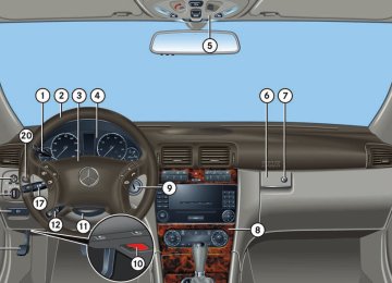
Practical hints Where will I find ...?
1 Vehicle tool kit 2 Arrow 3 Minispare wheel with spare wheel bolts
in container on wheel rim
4 Vehicle tool kit storage well casing 왘 Remove vehicle tool kit storage well
casing 4.
왘 Remove Minispare wheel 3.
359
Practical hints Where will I find ...?
Storing the Minispare wheel 왘 Place Minispare wheel 3 in wheel
well.
왘 Place vehicle tool kit storage well
casing 4 over the Minispare wheel. Make sure arrow 2 on vehicle tool kit storage well casing 4 points in the direction of travel.
왘 Place storage well casing (컄 page 356)
over vehicle tool kit storage well casing 4 and turn the retaining screw (컄 page 356) clockwise as far it will go to secure the Minispare wheel.
i Arrow 2 on vehicle tool kit storage well casing 4 must point in the direction of travel. Otherwise you cannot place the storage well cas- ing (컄 page 356) on top and secure the Minis- pare wheel with the retaining screw (컄 page 356).
! To prevent damage, always disengage trunk floor handle from upper edge of trunk and lower trunk floor before closing the trunk lid.
360
Warning!
Spare wheel bolts
The dimensions of the Minispare wheel are different from those of the road wheels. As a result, the vehicle handling characteristics change when driving with a Minispare wheel mounted.
The Minispare wheel should only be used temporarily, and should be replaced with a regular road wheel as quickly as possible.
In case of a flat tire, you may temporarily use the Minispare wheel when observing the following restrictions: 앫 Do not exceed a vehicle speed of
50 mph (80 km/h).
앫 Drive to the nearest tire repair facility
to have the flat tire repaired or replaced as appropriate.
앫 Do not operate vehicle with more than
one Minispare wheel mounted.
For more information, see “Rims and Tires” (컄 page 403).
1 Wheel bolt for light alloy rims 2 Wheel bolt for Minispare wheel (locat-
ed in trunk with spare wheel)
! Wheel bolts 2 must be used when mount- ing the Minispare wheel. The use of any wheel bolts other than wheel bolts 2 for the Minispare wheel will physically damage the vehicle’s brakes.
Warning!
Make sure to use the original length wheel bolts when remounting the original wheel after it has been repaired.
왔 Unlocking/locking in an emergency Unlocking the vehicle
Removing the mechanical key
Unlocking the driver’s door
Practical hints Unlocking/locking in an emergency
If you are unable to unlock the vehicle with the SmartKey, open the driver’s door and the trunk using the mechanical key.
i Unlocking and opening the driver’s door and/or the trunk with the mechanical key will trigger the anti-theft alarm system*. To cancel the alarm, do one of the following: 앫 Press button Œ or ‹ on the
SmartKey.
앫 Insert the SmartKey in the starter switch.
1 Mechanical key locking tab 2 Mechanical key 왘 Move locking tab 1 in direction of
1 Unlocking 왘 Insert the mechanical key into the
driver’s door lock until it stops.
arrow.
왘 Slide mechanical key 2 out of the
housing.
왘 Turn the mechanical key counterclock-
wise to position 1 until the locking knob moves up. The driver’s door is unlocked.
왘 Pull the door handle to open the
driver’s door.
361
Practical hints Unlocking/locking in an emergency
왘 Insert the mechanical key into the
Locking the vehicle
trunk lid lock until it stops.
왘 Turn the mechanical key
counterclockwise to position 1. The trunk lid unlocks.
왘 Pull on handle 2. The trunk opens.
! The trunk lid swings open upwards automatically. Always make sure there is suffi- cient overhead clearance. 왘 Turn the mechanical key back and remove it from the trunk lid lock.
If you can not lock the vehicle with the SmartKey, do the following: 왘 Close the passenger door, the rear
doors and the trunk.
왘 Press the central locking switch in the
center console (컄 page 100).
왘 Check to see whether the locking
knobs on the doors have moved down. 왘 If necessary push them down manually. 왘 Remove the mechanical key out of the
SmartKey (컄 page 361).
왘 Check whether the trunk is locked. 왘 If necessary, lock the trunk with the
mechanical key (컄 page 99).
왘 Close the driver’s door.
Except for the driver’s door, the vehicle should now be locked.
Unlocking and opening the trunk A minimum height clearance of 5.71 ft (1.74 m) is required to open the trunk lid. The trunk lid lock is located next to the handle above the rear license plate recess.
1 Unlocking in an emergency 2 Handle
362
Practical hints Unlocking/locking in an emergency
Manually unlocking the transmission gear selector lever
왘 Insert a tool 1 (e.g. flat blade screw
driver) into the opening.
In case of power failure, the transmission gear selector lever can be manually un- locked, e.g. to tow the vehicle. 왘 Slide out the swiveling cup holder
(컄 page 240).
1 Locking 왘 Insert the mechanical key into the
driver’s door lock until it stops.
왘 Turn the mechanical key clockwise to
position 1. The driver’s door is locked.
i This procedure does not arm the anti-theft alarm system, nor does it lock the fuel filler flap.
1 Tool
왘 Perform the following two steps
simultaneously: 왘 Press tool 1 forward in direction
of the arrow.
왘 Move gear selector lever from
position P.
왘 Remove tool 1 from the opening.
i The gear selector lever is locked again when moving it to position P.
363
Practical hints Opening/closing in an emergency
Power tilt/sliding sunroof*
You can open or close the tilt/sliding sunroof manually should an electrical malfunction occur. The tilt/sliding sunroof drive is located behind the lens 1 of the interior overhead light.
1 Lens 왘 Remove SmartKey from the starter
switch.
왘 Pry off lens 1 using a flat blade
screwdriver.
364
2 Locking tabs 왘 Slide both locking tabs 2 in direction
of the arrows.
3 Crank 왘 Insert crank 3 through hole on the left
side.
왘 Lower the rear of the cover. 왘 Remove the cover.
i Do not disconnect electrical connectors. 왘 Take the crank 3 out of the Mer-
cedes-Benz vehicle literature pouch.
왘 Turn crank 3 clockwise to:
앫 slide sunroof closed 앫 raise sunroof at the rear
왘 Turn crank 3 counterclockwise to:
앫 slide sunroof open 앫 lower sunroof at the rear
i Turn crank 3 slowly and smoothly. The tilt/sliding sunroof must be synchronized af- ter being operated manually (컄 page 226).
왔 Resetting activated head restraints Resetting activated head restraints
Warning!
If the active head restraints have been trig- gered in a rear-end collision, the active head restraints must be reset. Otherwise, the active head restraint cannot offer any additional protection in the event of anoth- er rear-end collision. You can tell that the head restraints have been triggered when they have been moved forward and cannot be adjusted.
i For your convenience, we recommend that you have this work carried out by an authorized Mercedes-Benz Center. You will find the reset tool for manually operating the active head restraints in the Mercedes-Benz vehicle literature pouch.
Warning!
For safety reasons, have the active head re- straints checked by an authorized Mercedes-Benz Center after a rear-end collision.
When pushing back the head restraint cush- ion, take care that your fingers do not be- come caught between the head restraint cushion and the cover. Failing to do so may lead to injury.
1 Head restraint cushion 2 Head restraint cover 3 Reset tool 4 Hole 왘 Take the reset tool 3 out of the Mercedes-Benz vehicle literature pouch.
Practical hints Resetting activated head restraints
왘 Guide reset tool 3 into the hole 4 be- tween the rear head restraint cover 2 and the head restraint cushion 1.
! Be careful not to damage upholstery. 왘 Press the reset tool 3 forward in di-
rection of the arrow.
왘 Press the reset tool 3 downward until
you hear the head restraint release mechanism audibly engage.
왘 Pull out reset tool 3. 왘 Firmly press the head restraint
cushion 1 back toward the rear head restraint cover 2 until it engages.
왘 Repeat this procedure on the active head restraint for the second front seat.
For information on active head restraints, see “Active head restraint” (컄 page 73). For information on head restraint adjust- ment, see “Seats” (컄 page 34).
365
Practical hints Replacing SmartKey batteries
If the batteries in the SmartKey are discharged, the vehicle can no longer be locked or unlocked. It is recommended to have the batteries replaced at an authorized Mercedes-Benz Center.
Warning!
Keep the batteries out of reach of children.
If a battery is swallowed, seek medical help immediately.
Batteries contain materials that can harm the environment if disposed of improperly. Recycling of batteries is the preferred method of disposal. Many states require sellers of batteries to accept old batteries for recycling.
i When inserting the batteries, make sure they are clean and free of lint.
i When replacing batteries, always replace both batteries of both SmartKeys. The required replacement batteries are available at any Mercedes-Benz Center.
366
SmartKey
Replacement batteries: Lithium, type CR 2025 or equivalent. 왘 Remove the mechanical key from the
SmartKey (컄 page 361).
왘 Pull battery compartment 2 out of the
housing.
1 Mechanical key 2 Battery compartment 왘 Insert mechanical key 1 into the
opening.
왘 Press mechanical key 1 in direction of
arrow. The battery compartment 2 is un- latched.
3 Batteries 4 Contact spring 왘 Remove the batteries 3. 왘 Using a lint-free cloth, insert new
batteries 3 under the contact springs 4 with the positive terminal (+) side facing up.
왘 Return battery compartment 2 into
housing until it locks into place.
왘 Slide mechanical key 1 back into the
SmartKey.
왘 Check the operation of the SmartKey.
Practical hints Replacing bulbs
왔 Replacing bulbs Safe vehicle operation depends on proper exterior lighting and signaling. It is there- fore essential that all bulbs and lamp assemblies are in good working order at all times.
Correct headlamp adjustment is extremely important. Have headlamps checked and readjusted at regular intervals and when a bulb has been replaced. See an authorized Mercedes-Benz Center for headlamp adjustment.
i If the headlamps or front fog lamps are fogged up on the inside as a result of high humidity, driving the vehicle a distance with the lights on should clear up the fogging.
i Substitute bulbs will be brought into use when lamps malfunction. Read and observe the messages in the multifunction display (컄 page 349).
367
Practical hints Replacing bulbs
Bulbs
368
Front lamps
Lamp
1 Additional turn signal
lamp
2 Halogen headlamp:
Type LED
Turn signal lamp Bi-Xenon* headlamp: Turn signal lamp
1156 A
2357 A
3 Halogen headlamp:
Low beam Bi-Xenon* headlamp: Low and high beam1
4 Halogen headlamp:High beam/high beam flasher Bi-Xenon* headlamp: High beam flasher Parking and standing lamp
H7 (55 W)
D2S-35 W
H7 (55 W)
H7 (55 W) W 5 W
1 Vehicles with Bi-Xenon* headlamps: Low beam and high beam use the same D2S-35W lamp. Do not replace the Xenon bulbs yourself. Contact an authorized Mercedes-Benz Center.
Lamp
5 Front fog lamp
Corner-illuminating front fog lamps* 6 Side marker lamp
Type HB4 (51 W) H7 (55 W)
W 5 W
Rear lamps
Lamp
7 High mounted brake
lamp
8 Brake lamp 9 Turn signal lamp a Parking and side
marker lamp b Backup lamp c License plate lamps d Rear fog lamp
(driver’s side only), tail and standing lamp
Type LED
P 21 W PY 21 W P 21/5 W
P 21 W C 5 W P 21/4 W
Warning!
Bulbs and bulb sockets can be very hot. Allow the lamp to cool down before changing a bulb.
Notes on bulb replacement 앫 Only use 12 volt bulbs of the same type
and with the specified watt rating.
앫 Switch lights off before changing a bulb
to prevent short circuits.
Keep bulbs out of reach of children.
앫 Always use a clean lint-free cloth when
Halogen lamps contain pressurized gas. A bulb can explode if you 앫 touch or move it when hot 앫 drop the bulb 앫 scratch the bulb Wear eye and hand protection.
Because of high voltage in Xenon lamps, it is dangerous to replace the bulb or repair the lamp and its components. We recommend that you have such work done by a qualified technician.
handling bulbs.
앫 Your hands should be dry and free of oil
and grease.
앫 If the newly installed bulb does not
come on, visit an authorized Mercedes-Benz Center.
Have the LEDs and bulbs for the following lamps replaced by an authorized Mercedes-Benz Center: 앫 Additional turn signals in the exterior
rear view mirrors
앫 High mounted brake lamp 앫 Xenon* lamps 앫 Front fog lamps 앫 Front side marker lamps
Practical hints Replacing bulbs
! Do not replace the LEDs yourself. You could otherwise damage the LEDs or parts of the vehicle. Only have the LEDs replaced by an authorized Mercedes-Benz Center.
369
Low beam bulb 왘 Press the clamp on housing cover 1
and remove it.
왘 Pull the electrical connector off. 왘 Turn bulb socket 4 counterclockwise
and take out the bulb.
왘 Insert the new bulb so that its socket
locates in the recess of the lamp housing.
왘 Turn bulb socket 4 clockwise until it
engages.
왘 Plug the electrical connector onto the
bulb.
왘 Align housing cover 1 and press until
it engages.
3 Bulb socket for turn signal lamp bulb 4 Bulb socket for low beam bulb 5 Bulb socket for high beam bulb 6 Bulb socket for parking and standing
lamp bulb
Practical hints Replacing bulbs
Replacing bulbs for front lamps
Before you start to replace a bulb for a front lamp, do the following first: 왘 Turn the exterior lamp switch to
position M (컄 page 109). 왘 Open the hood (컄 page 274).
Halogen headlamp
1 Housing cover for low beam headlamp 2 Housing cover for high beam head-
lamp, parking and standing lamp
370
High beam bulb 왘 Press the clamp on housing cover 2
and remove it.
Front turn signal lamp bulb 왘 Turn bulb socket 3 with the bulb
counterclockwise and remove it.
왘 Press gently onto the bulb and turn it
counterclockwise out of bulb socket 3.
왘 Press new bulb gently into bulb
socket 3 and turn clockwise until it engages.
왘 Place bulb socket 3 back into the
lamp and turn it clockwise.
왘 Pull the electrical connector off. 왘 Turn bulb socket 5 counterclockwise
and take out the bulb.
왘 Insert the new bulb so that its socket
locates in the recess of the lamp housing.
왘 Turn bulb socket 5 clockwise until it
engages.
왘 Plug the electrical connector onto the
bulb.
왘 Align housing cover 2 and press until
it engages.
Practical hints Replacing bulbs
Parking and standing lamp bulb 왘 Press the clamp on housing cover 2
and remove it.
왘 Pull out bulb socket 6 with the bulb. 왘 Pull the bulb out of bulb socket 6. 왘 Press the new bulb into bulb socket 6. 왘 Press bulb socket 6 back into the
lamp.
왘 Align housing cover 2 and press until
it engages.
371
High beam flasher bulb 왘 Press the clamp on housing cover 2
and remove it.
왘 Pull the electrical connector off. 왘 Turn bulb socket 4 counterclockwise
and take out the bulb.
왘 Insert the new bulb so that its socket
locates in the recess of the lamp housing.
왘 Turn bulb socket 4 clockwise until it
engages.
왘 Plug the electrical connector onto the
bulb.
왘 Align housing cover 2 and press until
it engages.
3 Bulb socket for turn signal lamp bulb 4 Bulb socket for high beam flasher bulb 5 Bulb socket for parking and standing
lamp bulb
Practical hints Replacing bulbs
Bi-Xenon* headlamp
Warning!
Do not remove the cover 1 for the Bi-Xenon headlamp. Because of high voltage in Bi-Xenon lamps, it is dangerous to replace the bulb or repair the lamp and its compo- nents. We recommend that you have such work done by a qualified technician.
1 Housing cover for Bi-Xenon headlamp 2 Housing cover for high beam flasher,
parking and standing lamp
372
Additional turn signal lamp bulbs The additional turn signal lamps in the exterior rear view mirrors have LEDs. If a malfunction occurs or LEDs fail to function, the entire turn signal unit must be replaced. Have the turn signal unit replaced by an authorized Mercedes-Benz Center.
Front side marker lamp bulbs Since replacing the side marker lamp bulbs is a technically highly demanding process, we recommend you have the side marker lamp bulbs replaced by an authorized Mercedes-Benz Center.
Front turn signal lamp bulb 왘 Turn bulb socket 3 with the bulb
counterclockwise and remove it.
왘 Press gently onto the bulb and turn it
counterclockwise out of bulb socket 3.
왘 Press new bulb gently into bulb
socket 3 and turn clockwise until it engages.
왘 Place bulb socket 3 back into the
lamp and turn it clockwise.
Parking and standing lamp bulb 왘 Press the clamp on housing cover 2
and remove it.
왘 Pull out bulb socket 5 with the bulb. 왘 Pull the bulb out of bulb socket 5. 왘 Press the new bulb into bulb socket 5. 왘 Press bulb socket 5 back into the
lamp.
왘 Align housing cover 2 and press until
it engages.
Practical hints Replacing bulbs
Replacing bulbs for rear lamps
Before you start to replace a bulb for a rear lamp, do the following first: 왘 Turn the exterior lamp switch to
position M (컄 page 109). 왘 Open the trunk (컄 page 96).
Tail lamp unit
1 Latch
컄컄
373
Practical hints Replacing bulbs
컄컄
왘 Fold the corresponding trim panel to
the side.
왘 Turn latch 1 to vertical position and
remove the bulb carrier.
Bulb carrier 2 Brake lamp bulb 3 Backup lamp bulb 4 Rear fog lamp (driver’s side only),
tail and standing lamp bulb
5 Parking and side marker lamp bulb 6 Turn signal lamp bulb
374
License plate lamp
왘 Press gently onto the respective bulb and turn counterclockwise out of its bulb socket.
왘 Press the new bulb gently into its bulb
socket and turn clockwise until it engages.
왘 Reinstall the bulb carrier and lock it
again with latch 1.
왘 Reinstall the trim panel.
1 Screw 2 License plate lamp 왘 Loosen both screws 1. 왘 Remove the license plate lamp 2. 왘 Replace the bulb. 왘 Reinstall the license plate lamp 2. 왘 Retighten screws 1.
왔 Replacing wiper blades Removing and installing wiper blades
Warning!
For safety reasons, switch off wipers and remove SmartKey from starter switch be- fore replacing a wiper blade. Otherwise, the wiper motor could suddenly turn on and cause injury.
Warning!
Wiper blades are components that are sub- ject to wear and tear. Change the wiper blades twice a year, preferably in the spring and fall. Otherwise the windows will not be properly wiped. As a result, you may not be able to observe surrounding traffic condi- tions and could cause an accident.
Practical hints Replacing wiper blades
! Never open the hood when the wiper arms are folded forward. For your convenience, we recommend that you have this work carried out by an authorized Mercedes-Benz Center. 왘 Remove SmartKey from starter switch.
Removing wiper blades
! Do not pull on the wiper blade inserts. They could tear.
왘 Pull the tab 2 in direction of arrow 1.
The wiper blade is unlocked.
왘 Lift up the wiper arm as far as you need
to remove the wiper blade.
! Hold on to the wiper arm. If released, the force of the impact from the tensioning spring could crack the windshield. 왘 Carefully fold the wiper arm back to
rest on the windshield.
1 Unlocking 2 Tab
375
왘 Lift up the wiper arm as far as you need to position the wiper blade under the wiper arm and hold it.
왘 Slide the tab 2 back in direction of
arrow 3 until it audibly engages. The wiper blade is locked.
! Make certain that the wiper blades are prop- erly installed. Improperly installed wiper blades may cause windshield damage.
! Hold on to the wiper arm. If released, the force of the impact from the tensioning spring could crack the windshield. 왘 Carefully fold the wiper arm back and
make sure that the taper piece 4 slides into the recess 1 at the wiper blade.
! Make certain that the square recess 5 on the taper piece 4 is on the top, otherwise the taper piece 4 cannot slide into the recess 1 at the wiper blade. If the square recess 5 is not at the top turn the taper piece 4 around to bring the square recess 5 to the top.
Practical hints Replacing wiper blades
Installing wiper blades
1 Recess 2 Tab 3 Locking 4 Taper piece 5 Square recess
376
왔 Flat tire
Warning!
The dimensions of the Minispare wheel are different from those of the road wheels. As a result, the vehicle handling characteristics change when driving with a Minispare wheel mounted. Adapt your driving style accord- ingly.
The Minispare wheel is for temporary use only. When driving with Minispare wheel mounted, ensure proper tire inflation pressure and do not exceed a vehicle speed of 50 mph (80 km/h).
Drive to the nearest Mercedes-Benz Center as soon as possible to have the Minispare wheel replaced with a regular road wheel.
Never operate the vehicle with more than one Minispare wheel mounted. Do not switch off the ESP® when a Minispare wheel is mounted.
Preparing the vehicle
Mounting the Minispare wheel
Practical hints Flat tire
Preparing the vehicle Prepare the vehicle as described (컄 page 377). 왘 Take the wheel wrench, alignment bolt, collapsible wheel chock, and the jack out of the trunk (컄 page 356).
왘 Take the Minispare wheel and wheel bolts out of the trunk (컄 page 359).
왘 Park the vehicle in a safe distance from
moving traffic on a hard, flat surface when possible.
왘 Turn on the hazard warning flasher
(컄 page 115).
왘 Turn the steering wheel so that the front wheels are in a straight ahead position.
왘 Set the parking brake (컄 page 54). 왘 Move the gear selector lever to P (manual transmission: to first or reverse gear).
왘 Turn off the engine (컄 page 55). 왘 Remove the SmartKey from the starter
switch.
왘 Have any passenger exit the vehicle at
a safe distance from the roadway.
i Open doors only when conditions are safe to do so.
377
Practical hints Flat tire
Lifting the vehicle 왘 Prevent the vehicle from rolling away by blocking wheels with wheel chocks or other sizable objects. One wheel chock is included with the vehicle tool kit (컄 page 356).
When changing wheel on a level surface: 왘 Place the wheel chock in front of and
another sizable object behind the wheel that is diagonally opposite to the wheel being changed.
Always try lifting the vehicle using the jack on a level surface. However, should cir- cumstances require you to do so on a hill, place the wheel chock and the other size- able object as follows: 왘 Place wheel chocks and another siz-
able object on the downhill side block- ing both wheels of the axle not being worked on.
Warning!
The jack is designed exclusively for jacking up the vehicle at the jack take-up brackets built into both sides of the vehicle. To help avoid personal injury, use the jack only to lift the vehicle during a wheel change. Never get beneath the vehicle while it is supported by the jack. Keep hands and feet away from the area under the lifted vehicle. Always firmly set parking brake and block wheels before raising vehicle with jack.
Do not disengage parking brake while the vehicle is raised. Be certain that the jack is always vertical (plumb line) when in use, especially on hills. Always try to use the jack on level surface. Make sure the jack arm is fully seated in the jack take-up bracket. Al- ways lower the vehicle onto sufficient ca- pacity jackstands before working under the vehicle.
378
왘 On wheel to be changed, loosen but do
not yet remove the wheel bolts (approximately one full turn with wrench).
The jack take-up brackets are located directly behind the front wheel housings and in front of the rear wheel housings.
Practical hints Flat tire
Removing the wheel
1 Take-up bracket 2 Jack 왘 Place jack 2 on firm ground. 왘 Position jack 2 under take-up
bracket 1 so that it is always vertical (plumb-line) as seen from the side, even if the vehicle is parked on an incline.
왘 Jack up the vehicle until the wheel is a
maximum of 1.2 in (3 cm) from the ground. Never start engine while vehicle is raised.
1 Alignment bolt 왘 Unscrew upper-most wheel bolt and
remove.
Warning!
왘 Replace this wheel bolt with alignment
bolt 1 supplied in the tool kit.
The jack is intended only for lifting the vehicle briefly for wheel changes. It is not suited for performing maintenance work under the vehicle. 앫 Never start the engine when the vehicle
is raised.
앫 Never lie down under the raised vehicle.
왘 Remove the remaining bolts.
! Do not place wheel bolts in sand or dirt. This could result in damage to the bolts and wheel hub threads. 왘 Remove the wheel.
379
Warning!
Always replace wheel bolts that are damaged or rusted.
Never apply oil or grease to wheel bolts.
Damaged wheel hub threads should be repaired immediately. Do not continue to drive under these circumstances! Contact an authorized Mercedes-Benz Center or call Roadside Assistance.
Incorrect wheel bolts or improperly tight- ened wheel bolts can cause the wheel to come off. This could cause an accident. Make sure to use the correct wheel bolts.
왘 Guide spare wheel onto the alignment
bolt and push it on.
왘 Insert wheel bolts and tighten them
slightly.
Practical hints Flat tire
Mounting the spare wheel
1 Wheel bolt for light alloy rims 2 Wheel bolt for Minispare wheel (locat-
ed in trunk with spare wheel)
! Wheel bolts 2 must be used when mount- ing the Minispare wheel. The use of any wheel bolts other than wheel bolts 2 for the Minispare wheel will physically damage the vehicle’s brakes. 왘 Clean contact surfaces of wheel and
wheel hub.
! To avoid paint damage, place wheel flat against hub and hold it there while installing first wheel bolt.
380
Lowering the vehicle 왘 Lower vehicle by turning crank
counterclockwise until vehicle is resting fully on its own weight.
왘 Remove the jack.
왘 Unscrew the alignment bolt, install last
wheel bolt and tighten slightly.
Warning!
Only use genuine equipment Mercedes-Benz wheel bolts. Other wheel bolts may come loose.
Do not tighten the wheel bolts when the vehicle is raised. Otherwise the vehicle could fall off the jack.
1 - 5 Wheel bolts 왘 Tighten the five wheel bolts evenly,
following the diagonal sequence illustrated (1 to 5), until all bolts are tight. Observe a tightening torque of 80 lb-ft (110 Nm).
Practical hints Flat tire
Warning!
Have the tightening torque checked after changing a wheel. The wheels could come loose if they are not tightened to a torque of 80 lb-ft (110 Nm).
Before storing the jack, it should be fully collapsed, with handle folded in (storage position) (컄 page 358). 왘 Store the jack and the other vehicle
tools in the trunk.
381
Practical hints Flat tire
MOExtended system*
The MOExtended system allows you to continue driving your vehicle even if there is a total loss of pressure in one or more tires. You may only use the MOExtended system in conjunction with the Run Flat Indicator*.
! The maximum distance in emergency mode depends on the vehicle’s load. It is 30 miles (50 km) if the vehicle is partially loaded and 18 miles (30 km) if the vehicle is fully loaded. The point at which the maximum driving distance begins in emergency mode is when the warning message appears in the multifunction display indicating that there is a loss of tire inflation pressure. Do not exceed the maximum speed of 50 mph (80 km/h).
382
Warning!
In emergency mode, your vehicle’s driving characteristics are diminished in such situa- tions as: 앫 driving around curves 앫 while braking 앫 while accelerating rapidly Therefore, your driving style must be adapt- ed accordingly. Avoid abrupt steering and driving maneuvers, as well as driving over obstacles (road curbs, potholes, or off-road areas). This is especially important if the ve- hicle is heavily loaded.
The emergency driving distance that can be achieved greatly depends on the demands placed on the vehicle. Depending on speed, load, driving maneuvers, road conditions, outside temperature, etc., the distance can be significantly shorter or, if the vehicle is driven cautiously, somewhat longer.
Do not continue driving in emergency mode if 앫 you notice knocking sounds 앫 the vehicle starts to shake 앫 smoke develops and you smell rubber 앫 ESP® is intervening continuously 앫 you notice tears on the tire sidewalls After driving in emergency mode, you must have the rims inspected by an authorized Mercedes-Benz Center to check if they are suitable for further use. The failed tire must be replaced in any case.
i When replacing individual or all tires on the vehicle, make sure only matching tires marked with “MOExtended” are mounted in the size specified for your vehicle (컄 page 403).
왔 Battery The battery is located in the engine compartment on the right hand side.
1 Clamps Removing filter box: 왘 Release clamps 1. 왘 Remove filter box. Installing filter box: 왘 Insert filter box properly. 왘 Secure it with clamps 1.
Practical hints Battery
Warning!
Warning!
Failure to follow these instructions can result in severe injury or death.
Do not place metal objects on the battery as this could result in a short circuit.
Observe all safety instructions and precautions when handling automotive batteries (컄 page 279). Never lean over batteries while connecting, you might get injured.
Battery fluid contains sulfuric acid. Do not allow this fluid to come in contact with eyes, skin or clothing. In case it does, immediately flush affected area with water and seek medical help if necessary.
A battery will also produce hydrogen gas, which is flammable and explosive. Keep flames or sparks away from battery, avoid improper connection of jumper cables, smoking, etc.
Use leak-proof battery only to avoid the risk of acid burns in the event of an accident.
! Never loosen or detach battery terminal clamps while the engine is running or the SmartKey is in the starter switch. Otherwise the alternator and other electronic components could be severely damaged. Have the battery checked regularly by an autho- rized Mercedes-Benz Center. Refer to Maintenance Booklet for maintenance intervals or contact an authorized Mercedes-Benz Center for further information.
383
Practical hints Battery
2 Negative terminal 3 Positive terminal cover
384
Disconnecting the battery
Warning!
With a disconnected battery 앫 you will no longer be able to turn the
SmartKey in the starter switch
앫 automatic transmission*: the gear se-
lector lever will remain locked in position P
! Always disconnect the battery in the order described below. Otherwise the vehicle’s electronics can be damaged. 왘 Apply the parking brake (컄 page 54). 왘 Make sure the gear selector lever* is set to position P (컄 page 153) (manual transmission: to Neutral (컄 page 149)).
왘 Turn off all electrical consumers. 왘 Remove SmartKey from starter switch. 왘 Open the hood (컄 page 274). 왘 Remove the filter box (컄 page 383).
왘 Read and observe safety instructions
and precautions (컄 page 279) and (컄 page 383).
왘 Disconnect the battery negative lead
from negative terminal 2.
왘 Remove cover 3 from the positive
terminal.
왘 Disconnect the battery positive lead.
Removing the battery
왘 Remove the screw-nuts securing the
battery.
왘 Remove the battery bracket. 왘 Pull out the battery ventilation hose
from the battery (depending on battery arrangement in your vehicle model, the ventilation hose is located either on the left or right side of the battery).
왘 Take out the battery.
Charging and reinstalling the battery
왘 Charge battery in accordance with the
Warning!
Never charge a battery while still installed in the vehicle unless the accessory battery charge unit approved by Mercedes-Benz is being used. Gases may escape during charg- ing and cause explosions that may result in paint damage, corrosion or personal injury.
An accessory battery charge unit specially adapted for Mercedes-Benz vehicles and tested and approved by Mercedes-Benz is available, permitting the charging of the bat- tery in its installed position. Contact an au- thorized Mercedes-Benz Center for information and availability. Charge battery in accordance with the separate instruc- tions for the accessory battery charger.
instructions of the battery charger manufacturer.
왘 Reinstall the charged battery. Follow
the previously described steps in reverse order.
! The battery, its filler caps and the battery ventilation hose must always be securely in- stalled when the vehicle is in operation.
Reconnecting the battery
! Always connect the battery in the order de- scribed below. Otherwise the vehicle’s electron- ics can be damaged. 왘 Turn off all electrical consumers. 왘 Remove SmartKey from starter switch.
! Never invert the terminal connections! 왘 Connect the battery positive lead and
fasten its cover 3 (컄 page 384).
왘 Connect the battery negative lead 2
(컄 page 384).
왘 Reinstall the filter box (컄 page 383).
Practical hints Battery
i The following procedures must be carried out following any interruption of battery power (e.g. due to reconnection): 앫 Set the clock (컄 page 136). Vehicles with COMAND*: See COMAND operator’s manual.
앫 Synchronize side windows (컄 page 222). 앫 Synchronize tilt/sliding sunroof*
(컄 page 226).
Batteries contain materials that can harm the environment if disposed of improperly. Large 12 volt storage batteries contain lead. Recycling of batteries is the preferred method of disposal. Many states require sellers of batteries to accept old batteries for recycling.
385
Practical hints Jump starting
Warning!
! Vehicles with automatic transmission and/or 4MATIC: Do not tow-start the vehicle.
Failure to follow these directions will cause damage to the electronic components, and can lead to a battery explosion and severe injury or death.
Never lean over batteries while connecting or jump starting, you might get injured.
Battery fluid contains sulfuric acid. Do not allow this fluid to come in contact with eyes, skin or clothing. In case it does, immediately flush affected area with water, and seek medical help if necessary.
A battery will also produce hydrogen gas, which is flammable and very explosive. Keep flames or sparks away from battery, avoid improper connection of jumper cables, smoking, etc.
Attempting to jump start a frozen battery can result in it exploding, causing personal injury.
Read all instructions before proceeding.
386
! Avoid repeated and lengthy starting attempts. Do not attempt to start the engine using a bat- tery quick charge unit. If engine does not run after several unsuccessful starting attempts, have it checked at the nearest authorized Mercedes-Benz Center. Excessive unburned fuel generated by repeated failed starting attempts may damage the catalyt- ic converter and may present a fire risk. Make sure the jumper cables do not have loose or missing insulation. Make sure the cable clamps do not touch any other metal part while the other end is still at- tached to a battery.
If the battery is discharged, the engine can be started with jumper cables and the battery of another vehicle. Observe the following: 앫 Jump starting should only be performed
when the engine and catalytic con- verter are cold.
앫 Do not start the engine if the battery is
frozen. Let the battery thaw out first.
앫 Only jump start from batteries with the
same voltage rating (12V). Jump starting with a higher voltage battery could damage the vehicle’s electrical system, which will not be covered by the Mercedes-Benz Limited Warranty. 앫 Only use jumper cables with sufficient
cross-section and insulated terminal clamps.
앫 Always make sure the jumper cables are not on or near pulleys, fans, or oth- er parts that move when an engine is started or running.
Warning!
Keep flames or sparks away from battery. Do not smoke.
Observe all safety instructions and precau- tions when handling automotive batteries (컄 page 279).
The battery is located in the engine compartment on the right hand side. The terminals for jump starting are located in front of the battery. 왘 Make sure the two vehicles do not
touch.
왘 Turn off all electrical consumers. 왘 Apply the parking brake (컄 page 54). 왘 Make sure the gear selector lever* is set to position P (컄 page 153) (manual transmission: to Neutral (컄 page 149)).
왘 Open the hood (컄 page 274). 왘 Flip up cover from the positive under hood terminal 2 in front of the filter box (컄 page 383).
1 Positive terminal of charged battery 2 Positive under hood terminal in front of
discharged battery
3 Negative under hood terminal in front
of discharged battery
4 Negative terminal of charged battery
! Never invert the terminal connections! 왘 Connect positive terminal 1 of the charged battery with positive under hood terminal 2 in front of the filter box with the jumper cable. Clamp cable to charged battery 1 first.
왘 Start engine of the vehicle with the
charged battery and run at idle speed.
Practical hints Jump starting
왘 Connect the negative terminal 4 of the charged battery with the negative under hood terminal 3 in front of the filter box with the second jumper cable. Clamp cable to charged battery 4 first.
왘 Start the engine of the disabled
vehicle.
You can now turn on the electrical con- sumers. Do not switch on the headlamps under any circumstances. 왘 Remove the jumper cables first from the negative terminals 3 and 4 and then from the positive terminals 2 and 1.
You can now switch on the headlamps. 왘 Have the battery checked at the near- est authorized Mercedes-Benz Center.
387
When circumstances do not permit the recommended towing methods, the vehicle may be towed with all wheels on the ground or front wheels raised (except vehicles with 4MATIC) only so far as necessary to have the vehicle moved to a safe location where the recommended towing methods can be employed.
! Vehicles with 4MATIC: Do not tow with one axle raised. Doing so could damage the transfer case, which is not covered by the Mercedes-Benz Limited Warranty. All wheels must be on or off the ground. Observe instructions for towing the vehicle with all wheels on the ground.
! If the vehicle is towed with the front axle raised (not permissible for vehicles with 4MATIC), the gear selector lever* must be in po- sition N (manual transmission: gear shift lever in neutral position) and the engine must be shut off (SmartKey in starter switch position 0 or 1). Oth- erwise the ESP® will immediately be engaged and will apply the rear wheel brakes. When towing the vehicle with all wheels on the ground, the gear selector lever* must be in position N (manual transmission: gears disen- gaged) and the SmartKey must be in starter switch position 2. When towing the vehicle with all wheels on the ground or the front axle raised, the vehicle may be towed only for distances up to 30 miles (50 km) and at a speed not to exceed 30 mph (50 km/h).
Practical hints Towing the vehicle
Mercedes-Benz recommends that the vehicle be transported with all wheels off the ground using flatbed or appropriate wheel lift/dolly equipment. This method is preferable to other types of towing.
! Vehicles with automatic transmission* and/or 4MATIC: Do not tow-start the vehicle.
! Use flatbed or wheel lift/dolly equipment with the SmartKey in the starter switch turned to position 0. Do not tow with sling-type equipment. Towing with sling-type equipment over bumpy roads will damage radiator and supports. To prevent damage during transport, do not tie down vehicle by its chassis or suspension parts. Switch off the automatic central locking (컄 page 143).
388
i To signal turns while being towed with the hazard warning flasher in use, switch on the igni- tion and activate the combination switch for the left or right turn signal in the usual manner – only the selected turn signal will operate. Upon canceling the turn signal, the hazard warn- ing flasher will operate again.
Warning!
With the engine not running, there is no power assistance for the brake and steering systems. In this case, it is important to keep in mind that a considerably higher degree of effort is necessary to brake and steer the ve- hicle. Adapt your driving accordingly.
Warning!
If circumstances require towing the vehicle with all wheels on the ground, always tow with a tow bar if: 앫 the engine will not run 앫 there is a malfunction in the power supply or in the vehicle’s electrical system
as that will be necessary to adequately control the towed vehicle.
Prior to towing the vehicle with all wheels on the ground, make sure the SmartKey is in starter switch position 2.
If the SmartKey is left in starter switch position 0 for an extended period of time, it can no longer be turned in the switch. In this case, the steering is locked. To unlock, remove SmartKey from starter switch and reinsert.
Practical hints Towing the vehicle
! When towing the vehicle with all wheels on the ground, please note the following: With the automatic central locking activated and the SmartKey in starter switch position 2, the ve- hicle doors lock if the left front wheel as well as the right rear wheel are turning at vehicle speeds of approx. 9 mph (15 km/h) or more. To prevent the vehicle doors from locking, deac- tivate the automatic central locking (컄 page 143). Towing of the vehicle should only be done using the properly installed towing eye bolt. Never at- tach tow cable, tow rope or tow rod to vehicle chassis, frame or suspension parts.
i If the battery is disconnected or discharged 앫 the SmartKey will not turn in the starter
switch. For more information, see “Battery” (컄 page 383) and “Jump starting” (컄 page 386).
앫 the gear selector lever will remain locked in position P. For information on manually un- locking the transmission gear selector lever see (컄 page 363).
389
Practical hints Towing the vehicle
Installing towing eye bolt
1 Cover on right side of front bumper
2 Cover on right side of rear bumper
Removing cover 왘 Press mark on cover 1 or 2 in
direction of arrows.
왘 Lift cover off to reveal the threaded
hole for towing eye bolt.
The towing eye bolt is supplied with the tool kit (located in the compartment under- neath the trunk floor). 왘 Screw towing eye bolt in to its stop and
tighten with lug wrench.
Reinstalling cover 왘 Fit cover 1 or 2 and snap into place.
390
왔 Fuses The electrical fuses in your vehicle serve to switch off malfunctioning power circuits. If a fuse is blown, the components and sys- tems secured by that fuse will stop operat- ing.
Warning!
Only use fuses approved by Mercedes-Benz with the specified amperage for the system in question and do not attempt to repair or bridge a blown fuse. Using other than ap- proved fuses or using repaired or bridged fuses may cause an overload leading to a fire, and/or cause damage to electrical components and/or systems. Have the cause determined and remedied by an authorized Mercedes-Benz Center
i A blown fuse must be replaced by an appro- priate spare fuse (recognizable by its color or the fuse rating given on the fuse) of the amperage recommended in the fuse chart. Any Mercedes-Benz Center will be glad to advise you on this subject.
If a newly inserted fuse blows again, have the cause determined and rectified by an authorized Mercedes-Benz Center. The following aids are available to help you replace fuses. 앫 Fuse chart
The fuse chart is located in the main fuse box in the passenger compart- ment (컄 page 392). The fuse chart ex- plains the fuse allocation and fuse amperages. 앫 Spare fuses
Spare fuses are located in the vehicle tool kit in the spare wheel well (컄 page 356). 앫 Fuse extractor
The fuse extractor is located in the cov- er of the auxiliary fuse box in the trunk (컄 page 394).
Practical hints Fuses
The electrical fuses are located in different fuse boxes: 앫 in the passenger compartment on the
driver’s side (컄 page 392)
앫 on the driver’s side of the engine com-
partment (컄 page 392)
앫 in the trunk (컄 page 394) Before replacing fuses: 왘 Apply the parking brake (컄 page 54). 왘 Make sure the gear selector lever* is set to position P (컄 page 153) (manual transmission: to Neutral (컄 page 149)).
왘 Turn off all electrical consumers. 왘 Turn off the engine (컄 page 55). 왘 Remove the SmartKey from the starter
switch.
391
Practical hints Fuses
Main fuse box in passenger compartment
The main fuse box is located in the passen- ger compartment on the driver’s side of the cockpit.
1 Main fuse box cover
392
Fuse box in engine compartment
The fuse box is located in the engine compartment on the driver’s side.
Opening fuse box 왘 Open the driver’s door. 왘 Pull fuse box cover 1 open with a
screw driver or similar tool (see arrow).
왘 Remove fuse box cover 1 rearward.
Closing fuse box 왘 Attach fuse box cover 1 in the front. 왘 Fold fuse box cover 1 in until it
engages.
1 Cover 2 Screws 3 Retainer
Removing cover 왘 Twist screws 2
90° counterclockwise.
왘 Lift the rear of cover 1. 왘 Slide out retainer 3 and remove cover 1 by pulling towards front.
Practical hints Fuses
Closing fuse box 왘 Make sure that the sealing rubber is
Installing cover 왘 Insert cover 1 sideways into
properly positioned.
retainer 3.
왘 Press fuse box cover 4 down and
왘 Twist screws 2 90° clockwise.
secure with clamps 5.
! The fuse box cover 4 must be properly po- sitioned as described to prevent moisture or dirt from entering the fuse box and possibly impair- ing fuse operation.
Opening fuse box
4 Fuse box cover 5 Clamps 왘 With a dry cloth, remove any moisture
from the fuse box. 왘 Release clamps 5. 왘 Remove fuse box cover 4.
393
Practical hints Fuses
Fuse box in trunk
The fuse box is located in the trunk behind the left-hand trim panel.
Opening fuse box 왘 Pull away trim panel 1. 왘 Remove fuse box cover 3.
Closing fuse box 왘 Insert fuse box cover 3. 왘 Insert trim panel 1.
1 Trim panel 2 Fuse extractor 3 Fuse box cover
394
Technical data
Parts service Warranty coverage Identification labels Layout of poly-V-belt drive Engine Rims and Tires Electrical system Main dimensions and weights Weights Fuels, coolants, lubricants, etc.
395
Technical data Parts service
The “Technical data” section provides the necessary technical data for your vehicle.
! The use of non-genuine Mercedes-Benz parts and accessories not authorized by Mercedes-Benz could damage the vehicle, which is not covered by the Mercedes-Benz Limited Warranty, or could compromise the vehicle’s durability or safety.
All authorized Mercedes-Benz Centers maintain a stock of Genuine Mercedes-Benz parts required for mainte- nance and repair work. In addition, strate- gically located parts distribution centers provide quick and reliable parts service. More than 300000 different parts for Mercedes-Benz models are available. Genuine Mercedes-Benz parts are subject to stringent quality inspections. Each part has been specifically developed, manufac- tured or selected for and adapted to Mercedes-Benz vehicles. Therefore, Genuine Mercedes-Benz parts should be installed.
396
Technical data Warranty coverage
Replacement parts and accessories are covered by the Mercedes-Benz Parts and Accessories warranties, copies of which are available at any Mercedes-Benz Center.
Loss of Service and Warranty Information Booklet
Should you lose your Service and Warranty Information booklet, have an authorized Mercedes-Benz Center arrange for a replacement. It will be mailed to you.
왔 Warranty coverage Your vehicle is covered under the terms of the warranties printed in the Service and Warranty Information booklet. Your authorized Mercedes-Benz Center will ex- change or repair any defective parts origi- nally installed in the vehicle in accordance with the terms of the following warranties: 앫 New Vehicle Limited Warranty 앫 Emission System Warranty 앫 Emission Performance Warranty 앫 California, Maine, Massachusetts, and
Vermont Emission Control Systems Warranty
397
Technical data Identification labels
1 Certification label (on driver’s B-pillar) The Vehicle Identification Number (VIN) can be found in the following locations: 앫 on the certification label. 앫 embossed underneath the carpet in
front of the front passenger seat (컄 page 399).
앫 on the lower edge of the windshield
(컄 page 399).
Example certification label (U.S. vehicles) 2 VIN 3 Paintwork code
Example certification label (Canada vehicles) 2 VIN 3 Paintwork code
i Data shown on certification label are for illustration purpose only. These data are specific to each vehicle and may vary from data shown in the illustration. Refer to certification label on vehicle for actual data specific to your vehicle.
398
4 Carpet 5 VIN 왘 Move the front passenger seat to the
rear as far as possible.
왘 Fold carpet 4 in direction of arrow.
VIN 5 is visible.
6 Emission control information label, includes both federal and California certification exhaust emission standards
7 Vacuum line routing diagram label 8 Engine number (engraved on engine) 9 VIN (lower edge of windshield)
i When ordering parts, please specify vehicle identification and engine numbers.
Technical data Identification labels
399
Technical data Layout of poly-V-belt drive
All models 1 Idler pulley 2 Idler pulley 3 Automatic belt tensioner 4 Power steering pump 5 Air conditioning compressor 6 Crankshaft 7 Coolant pump 8 Generator (alternator)
400
Technical data Engine
왔 Engine Model
Engine Mode of operation No. of cylinders Bore Stroke Total piston displacement Compression ratio Output acc. to SAE J 1349
Maximum torque acc. to SAE J 1349
Maximum engine speed Firing order Poly-V-belt 1 The quoted data apply only to the standard vehicle. See an authorized Mercedes-Benz Center for the corresponding data of all special bodies and special equipment. 2 Premium fuel required. Performance may vary with fuel octane rating.C 230 (203.052)1
C 230 Sport (203.052)1
272
4-stroke engine, gasoline injection 3.46 in (88.00 mm) 2.69 in (68.40 mm) 152.3 cu in (2496 cm3) 11.2:1
201 hp/6200 rpm2
(150 kW/6200 rpm) 181 lb-ft/2700 – 5500 rpm (245 Nm/2700 – 5500 rpm) 6500 rpm 1-4-3-6-2-5
2404 mmC 280 (203.054)1
C 280 4MATIC (203.092)1
272
4-stroke engine, gasoline injection 3.46 in (88.00 mm) 3.23 in (82.10 mm) 182.8 cu in (2996 cm3) 11.3:1
228 hp/6000 rpm2
(170 kW/6000 rpm) 221 lb-ft/2700 – 5000 rpm (300 Nm/2700 – 5000 rpm) 6500 rpm 1-4-3-6-2-5
2404 mm401
Technical data Engine
Model
C 350 (203.056)1
C 350 Sport (203.056)1
C 350 4MATIC (203.087)1
272
4-stroke engine, gasoline injection 3.65 in (92.90 mm) 3.38 in (86.00 mm) 213.5 cu in (3498 cm3) 10.7:1
268 hp/6000 rpm2
(200 kW/6000 rpm) 258 lb-ft/2400 – 5000 rpm (350 Nm/2400 – 5000 rpm) 6500 rpm 1-4-3-6-2-5
2404 mmEngine Mode of operation No. of cylinders Bore Stroke Total piston displacement Compression ratio Output acc. to SAE J 1349
Maximum torque acc. to SAE J 1349
Maximum engine speed Firing order Poly-V-belt 1 The quoted data apply only to the standard vehicle. See an authorized Mercedes-Benz Center for thecorresponding data of all special bodies and special equipment.
2 Premium fuel required. Performance may vary with fuel octane rating.