- Download PDF Manual
-
Only use brake/clutch fluid in brake/clutch system. Small amounts of improper fluids (such as engine oil) can cause damage to the brake/clutch sys- tem.
OYD076024L Check the fluid level in the reservoir periodically. The fluid level should be between MAX and MIN marks on the side of the reservoir. Before removing the reservoir cap and adding brake/clutch* fluid, clean the area around the reservoir cap thoroughly to prevent brake/clutch* fluid contamination.
* if equipped
If the level is low, add fluid to the MAX level. The level will fall with accumulated mileage. This is a nor- mal condition associated with the wear of the brake linings and/or clutch disc (if equipped). If the fluid level is excessively low, have the brake/clutch* system checked by an authorized Kia dealer.
Use only the specified brake/clutch* fluid.(Refer to “Recommended lubri- cants and capacities”in chapter 8.)
Never mix different types of fluid.
and
changing
In the event the brake/clutch* system requires frequent additions of fluid, the vehicle should be inspected by an authorized Kia dealer. When adding brake/clutch* fluid, handle it carefully. Do not let it come in contact with your eyes. If brake/clutch* fluid should come in contact with your eyes, immediately flush them with a large quantity of fresh tap water. Have your eyes examined by a doc- tor as soon as possible.
CAUTION - Brake/clutch
fluid
Do not allow brake/clutch* fluid to contact the vehicle's body paint, as paint damage will result.
Brake/clutch* fluid, which has been exposed to open air for an extended time should never be used as its quality cannot be guaranteed. It should be disposed of properly.
7 35
YDM USA 7.QXP 5/1/2016 1:23 PM Page 36
Maintenance
WASHER FLUID Checking the washer fluid level
OMD070007
Check the fluid level in the washer fluid reservoir and add fluid if neces- sary. Plain water may be used if washer is not available. However, use washer solvent with antifreeze characteristics in cold cli- mates to prevent freezing.fluid
36
WARNING - Coolant
(cid:129) Do not use radiator coolant or antifreeze in the washer fluid reservoir.
(cid:129) Radiator coolant can severely obscure visibility when sprayed on the windshield and may cause loss of vehicle control.
WARNING - Windshield
fluid
Do not drink the windshield washer fluid. The windshield washer fluid is poisonous to humans and animals.
WARNING - Flammable
fluid
Do not allow the washer fluid to come in contact with open flames or sparks.The windshield washer fluid reservoir is flamma- ble under certain circumstances. This can result in a fire.
PARKING BRAKE Checking the parking brake
OYDDDR2105
Check the stroke of the parking brake by counting the number of “clicks’’ heard while fully applying it from the released position. Also, the parking brake alone should securely hold the vehicle on a fairly steep grade. If the stroke is more or less than specified, have the parking brake adjusted by an authorized Kia dealer.
Stroke : 6~8 “clicks’’ at a force of 44
lbs (20 kg, 196 N).
YDM USA 7.QXP 5/1/2016 1:24 PM Page 37
AIR CLEANER Filter replacement
Maintenance
OMD070010
It must be replaced when necessary, and should not be washed. You can clean the filter when inspect- ing the air cleaner element. Clean the filter by using compressed air.
OMD070011
1. Loosen the air cleaner cover attaching clips and open the cover.OMD070012
2. Wipe the inside of the air cleaner. 3. Replace the air cleaner filter. 4. Lock the cover with the coverattaching clips.
7 37
YDM USA 7.QXP 5/1/2016 1:24 PM Page 38
Maintenance
Replace the filter according to the Maintenance Schedule. If the vehicle is operated in extreme- ly dusty or sandy areas, replace the element more often than the usual recommended intervals. (Refer to “Maintenance under severe usage conditions”in this chapter.)
CAUTION - Air filter
maintenance
(cid:129) Do not drive with the air clean- er removed;this will result in excessive engine wear.
(cid:129) When removing the air cleaner filter, be careful that dust or dirt does not enter the air intake,or damage may result. (cid:129) Use a Kia genuine part.Use of nongenuine part could dam- age the air flow sensor.
38
YDM USA 7.QXP 5/1/2016 1:24 PM Page 39
to
replaced according
CLIMATE CONTROL AIR FILTER (IF EQUIPPED) Filter inspection Filter replacement The climate control air filter should be the Maintenance Schedule. If the vehicle is operated in severely air-polluted cities or on dusty rough roads for a long period, it should be inspected more frequently and replaced earlier. When you replace the climate control air filter, replace it performing the fol- lowing procedure, and be careful to avoid damaging other components.
OYDDMC2006
1. Open the glove box and pull the
support strap (1).
Maintenance
OYDDMC2005
2. With the glove box open, removethe stoppers on both sides.
7 39
YDM USA 7.QXP 5/1/2016 1:24 PM Page 40
Maintenance
OYDDMC2007
3. Remove the climate control air fil- ter case by pulling out both sides of the cover.OMG079027
4. Replace the climate control air fil-ter.
5. Reassemble in the reverse order
of disassembly.
When replacing the climate control air filter install it properly. Otherwise, the system may produce noise and the effectiveness of the filter may be reduced.
40
YDM USA 7.QXP 5/1/2016 1:24 PM Page 41
WIPER BLADES Blade inspection
1JBA5122
Commercial hot waxes applied by automatic car washes have been known to make the windshield diffi- cult to clean.
Maintenance
Blade replacement When the wipers no longer clean adequately, the blades may be worn or cracked, and require replacement. To prevent damage to the wiper arms or other components, do not attempt to move the wipers manually. The use of a non-specified wiper blade could result in wiper malfunc- tion and failure.
Contamination of either the wind- shield or the wiper blades with for- eign matter can reduce the effective- ness of the windshield wipers. Common sources of contamination are insects, tree sap, and hot wax treatments used by some commer- cial car washes. If the blades are not wiping properly, clean both the win- dow and the blades with a good cleaner or mild detergent, and rinse thoroughly with clean water.
CAUTION - Wiper blades
To prevent damage to the wiper blades, do not use gasoline, kerosene,paint thinner,or other solvents on or near them.
7 41
YDM USA 7.QXP 5/1/2016 1:24 PM Page 42
Maintenance
Front windshield wiper blade
CAUTION - Wiper arms
Do not allow the wiper arm to fall against the windshield, since it may chip or crack the windshield.
1JBA7037
OHM078059
Type B 1. Raise the wiper arm.
1LDA5023
Type A 1. Raise the wiper arm and turn the wiper blade assembly to expose the plastic locking clip.
1JBA7038
2. Compress the clip (1) and slide the blade assembly downward (2).3. Lift it off the arm. 4. Install the blade assembly in the
reverse order of removal.
42
YDM USA 7.QXP 5/1/2016 1:24 PM Page 43
OHM078060
2. Lift up the wiper blade clip. Then pull down the blade assembly and remove it.OHG070043
3. Install the new blade assembly inthe reverse order of removal.
Maintenance
7 43
YDM USA 7.QXP 5/1/2016 1:24 PM Page 44
Maintenance
BATTERY For best battery service
OYDDMC2008
(cid:129) Keep the battery securely mount-
ed.
(cid:129) Keep the battery top clean and dry. (cid:129) Keep the terminals and connec- tions clean, tight, and coated with petroleum jelly or terminal grease. (cid:129) Rinse any spilled electrolyte from the battery immediately with a solution of water and baking soda. (cid:129) If the vehicle is not going to be used for an extended time, discon- nect the battery cables.
44
WARNING - Risk of
explosion
WARNING - Sulfuric acid in batteries
Keep lit cigarettes and all other flames or sparks away from the battery. The battery contains hydrogen -- a highly combustible gas which will explode if it comes in contact with a flame or spark.
of
Keep batteries out of the reach children because batteries con- tain highly corrosive SULFURIC ACID and electrolytes. Do not allow battery acid to contact your skin, eyes, clothing or paint finish. Wear eye protection when charging or work- ing near a battery. Always provide ventila- tion when working in an enclosed space.
YDM USA 7.QXP 5/1/2016 1:24 PM Page 45
Always read the following instructions carefully when handling a battery. If any electrolyte gets into your eyes, flush your eyes with clean water for at least 15 minutes and get immedi- ate medical attention. If electrolyte gets on your skin, thoroughly wash the contacted area. If you feel pain or burning sensation, get medical attention imme- diately. An inappropriately disposed battery can be harmful to the environment and human health. Dispose the battery according to your local law(s) or regulation. The battery contains lead. Do not dispose of it after use. Please return the battery to an authorized Kia dealer to be recycled.
WARNING - Recharging
battery
Never attempt to recharge the battery when the battery cables are connected.
When the vehicle remains unused for a long time while tempertures are low, disconnect the battery and keep it indasrs.
WARNING - California proposition 65
Battery posts, terminals, and related accessories contain lead and lead compounds, chemicals known to the State of California to cause cancer, birth defects and reproductive harm. Batteries also contain other chemicals known to the State of California to cause cancer. Wash hands after handling.
Maintenance
WARNING - Risk of elec-
trocution
Never touch the electrical igni- tion system while the vehicle is running. This system works with high voltage which can "zap" you.
7 45
YDM USA 7.QXP 5/1/2016 1:24 PM Page 46
Maintenance
Battery recharging Your vehicle has a maintenance-free, calcium-based battery. (cid:129) If the battery becomes discharged in a short time (because, for exam- ple, the headlights or interior lights were left on while the vehicle was not in use), recharge it by slow charging (trickle) for 10 hours.
(cid:129) If the battery gradually discharges because of high electric load while the vehicle is being used, recharge it at 20-30A for two hours.
recharging
the battery,
When observe the following precautions: (cid:129) The battery must be removed from the vehicle and placed in an area with good ventilation.
(cid:129) Watch the battery during charging, and stop or reduce the charging rate if the battery cells begin gassing (boiling) violently or if the temperature of the electrolyte of any cell exceeds 120°F (49°C).
(cid:129) Wear eye protection when check-
ing the battery during charging.
Reset items Items should be reset after the bat- tery has been discharged or the bat- tery has been disconnected. (cid:129) Auto down window (See chapter 4) (cid:129) Sunroof (See chapter 4) (cid:129) Trip computer (See chapter 4) (cid:129) Climate control system
(See chapter 4)
(cid:129) Clock (See chapter 4) (cid:129) Audio (See chapter 4)
(cid:129) Disconnect the battery charger in
the following order. 1. Turn off the battery charger main
switch.
2. Unhook the negative clamp from
the negative battery terminal.
3. Unhook the positive clamp from
the positive battery terminal.
(cid:129) Before performing maintenance or recharging the battery, turn off all accessories and stop the engine. (cid:129) The negative battery cable must be removed first and installed last when the battery is disconnected.
46
YDM USA 7.QXP 5/1/2016 1:24 PM Page 47
TIRES AND WHEELS Tire care For proper maintenance, safety, and maximum fuel economy, you must always maintain recommended tire inflation pressures and stay within the load limits and weight distribution recommended for your vehicle.
Recommended cold tire infla- tion pressures All tire pressures (including the spare) should be checked when the tires are cold. “Cold Tires” means the vehicle has not been driven for at least three hours or driven less than one mile (1.6 km). Recommended pressures must be maintained for the best ride, top vehi- cle handling, and minimum tire wear. For recommended inflation pressure refer to “Tire and wheels” in section 8.
Maintenance
WARNING - Tire underin-
flation
Inflate your tires consistent with the instructions provided in this manual. Severe underinflation (10 psi (70 kPa) or more) can lead to severe heat build-up, causing blowouts, tread separa- tion and other tire failures that can result in the loss of vehicle control.This risk is much higher on hot days and when driving for long periods at high speeds.
OMD060012N All specifications (sizes and pres- sures) can be found on a label attached to the driver’s side center pillar.
7 47
YDM USA 7.QXP 5/1/2016 1:24 PM Page 48
Maintenance
results
(cid:129) Underinflation also
in excessive wear, poor handling and reduced fuel economy. Wheel deformation also is possible. Keep your tire pressures at the proper levels. If a tire frequently needs refilling, have it checked by an authorized Kia dealer.
(cid:129) Overinflation produces a harsh ride, excessive wear at the center of the tire tread, and a greater pos- sibility of damage from road haz- ards.
(cid:129) Warm tires normally exceed rec- ommended cold tire pressures by 4
to 6 psi (28 to 41 kPa). Do not release air from warm tires to adjust the pressure or the tires will be underinflated.(cid:129) Be sure to reinstall the tire inflation valve caps. Without the valve cap, dirt or moisture could get into the valve core and cause air leakage. If a valve cap is missing, install a new one as soon as possible.
48
Always observe the following: (cid:129) Check tire pressure when the tires are cold. (After vehicle has been parked for at least three hours or hasn't been driven more than one mile (1.6 km) since startup.)
(cid:129) Check the pressure of your spare tire each time you check the pres- sure of other tires.
(cid:129) Never overload your vehicle. Be careful not to overload a vehicle luggage rack if your vehicle is equipped with one.
WARNING - Tire Inflation Overinflation or underinflation can reduce tire life, adversely affect vehicle handling, and lead to sudden tire failure. This could result in loss of vehicle control and potential injury.
Checking tire inflation pres- sure Check your tires once a month or more. Also, check the tire pressure of the spare tire.
How to check Use a good quality gauge to check tire pressure. You can not tell if your tires are properly inflated simply by looking at them. Radial tires may look properly inflated even when they're underinflated. Check the tire's inflation pressure when the tires are cold. - "Cold" means your vehicle has been sitting for at least three hours or driven no more than 1 mile (1.6 km).
YDM USA 7.QXP 5/1/2016 1:24 PM Page 49
Remove the valve cap from the tire valve stem. Press the tire gauge firm- ly onto the valve to get a pressure measurement. If the cold tire inflation pressure matches the recommended pressure on the tire and loading information label, no further adjust- ment is necessary. If the pressure is low, add air until you reach the rec- ommended amount. If you overfill the tire, release air by pushing on the metal stem in the center of the tire valve. Recheck the tire pressure with the tire gauge. Be sure to put the valve caps back on the valve stems. They help prevent leaks by keeping out dirt and mois- ture.
(cid:129) Inspect your tires frequently for proper inflation as well as wear and damage. Always use a tire pres- sure gauge.
(cid:129) Tires with too much or too little pressure wear unevenly causing poor handling, loss of vehicle con- trol, and sudden tire failure leading to accidents, injuries, and even death. The recommended cold tire pressure for your vehicle can be found in this manual and on the tire label located on the driver's side center pillar.
(cid:129) Remember to check the pressure of your spare tire. Kia recommends that you check the spare every time you check the pressure of the other tires on your vehicle.
Maintenance
Tire rotation To equalize tread wear, it is recom- mended that the tires be rotated every 7,500 miles (12,000 km) or sooner if irregular wear develops. During rotation, check the tires for correct balance. When rotating tires, check for uneven wear and damage. Abnormal wear is usually caused by incorrect tire pres- sure, improper wheel alignment, out- of-balance wheels, severe braking or severe cornering. Look for bumps or bulges in the tread or side of tire. Replace the tire if you find either of these conditions. Replace the tire if fabric or cord is visible. After rotation, be sure to bring the front and rear tire pressures to specification and check lug nut tightness. Refer to “Tire and wheels” in chapter 8.
7 49
YDM USA 7.QXP 5/1/2016 1:24 PM Page 50
Maintenance
Without a spare tire
Directional tires (if equipped)
S2BLA790A
CBGQ0707A Disc brake pads should be inspected for wear whenever tires are rotated.
50
Rotate radial tires that have an direc- tional tread pattern only from front to rear and not from right to left. Do not use the compact spare tire for tire rotation.
WARNING - Mixing tire
types
Do not mix bias ply and radial ply tires under any circum- stances. This may cause unusu- al handling characteristics.
Wheel alignment and tire bal- ance The wheels on your vehicle were aligned and balanced carefully at the factory to give you the longest tire life and best overall performance. In most cases, you will not need to have your wheels aligned again. However, if you notice unusual tire wear or your vehicle pulling one way or the other, the alignment may need to be reset. If you notice your vehicle vibrating when driving on a smooth road, your wheels may need to be rebalanced.
CAUTION - Wheel weight
Improper wheel weights can damage your vehicle's alu- minum wheels. Use only approved wheel weights.
YDM USA 7.QXP 5/1/2016 1:24 PM Page 51
Tire replacement
Tread wear indicator
OEN076053
If the tire is worn evenly, a tread wear indicator will appear as a solid band across the tread. This shows there is less than 1/16 inch (1.6 mm) of tread left on the tire. Replace the tire when this happens. Do not wait for the band to appear across the entire tread before replac- ing the tire.
Maintenance
The ABS works by comparing the speed of the wheels. Tire size can affect wheel speed. When replacing tires, all 4 tires must use the same size originally supplied with the vehi- cle. Using tires of a different size can cause the ABS (Anti-lock Brake System) and ESC (Electronic Stability Control) (if equipped) to work irregularly.
✽✽ NOTICE We recommend replacing tires with the same make and model originally supplied with the vehicle; not doing so may affect driving performance.
Compact spare tire replacement A compact spare tire has a shorter tread life than a regular size tire. Replace it when you can see the tread wear indicator bars on the tire. The replacement compact spare tire should be the same size and design tire as the one provided with your new vehicle and should be mounted on the same compact spare tire wheel. The compact spare tire is not designed to be mounted on a regular size wheel, and the compact spare tire wheel is not designed for mount- ing a regular size tire.
7 51
YDM USA 7.QXP 5/1/2016 1:24 PM Page 52
Maintenance
Wheel replacement When replacing the metal wheels for any reason, make sure the new wheels are equivalent to the original factory units in diameter, rim width and offset. A wheel that is not the correct size may adversely affect wheel and bearing life, braking and stopping abilities, handling characteristics, ground clearance, body-to-tire clear- ance, clearance, speedometer and odometer calibra- tion, headlight aim and bumper height.
chain
snow
CAUTION - Wheel
Wheels that do not meet Kia's specifications may fit poorly and result in damage to the vehicle or unusual handling and poor vehicle control.
52
Tire traction Tire traction can be reduced if you drive on worn tires, tires that are improperly inflated or on slippery road surfaces. Tires should be replaced when tread wear indicators appear. Slow down whenever there is rain, snow or ice on the road, to reduce the possibility of losing con- trol of the vehicle.
Tire maintenance In addition to proper inflation, correct wheel alignment helps to decrease tire wear. If you find a tire is worn unevenly, have your dealer check the wheel alignment. When you have new tires installed, make sure they are balanced. This will increase vehicle ride comfort and tire life. Additionally, a tire should always be rebalanced if it is removed from the wheel.
Tire sidewall labeling
5,6
I030B04JM
information
This identifies and describes the fundamental charac- teristics of the tire and also provides the tire identification number (TIN) for safety standard certification. The TIN can be used to identify the tire in case of a recall.
1.Manufacturer or brand name Manufacturer or Brand name is shown.
YDM USA 7.QXP 5/1/2016 1:24 PM Page 53
2.Tire size designation A tire’s sidewall is marked with a tire size designation. You will need this information when selecting replace- ment tires for your car. The following explains what the letters and num- bers in the tire size designation mean. Example tire size designation: (These numbers are provided as an example only; your tire size designa- tor could vary depending on your vehicle.) P205/55R16 89H P - Applicable vehicle type (tires marked with the prefix “P’’ are intended for use on passenger vehicles or light trucks; however, not all tires have this marking).
205 - Tire width in millimeters. 55 - Aspect ratio. The tire’s section height as a percentage of its width.
R - Tire construction code (Radial). 16 - Rim diameter in inches.
89 - Load Index, a numerical code associated with the maximum load the tire can carry.
H - Speed Rating Symbol. See the speed rating chart in this section for additional information.
Wheel size designation Wheels are also marked with impor- tant information that you need if you ever have to replace one. The follow- ing explains what the letters and numbers in the wheel size designa- tion mean.
Example wheel size designation: 6.0JX16
6.0 - Rim width in inches. J - Rim contour designation. 16 - Rim diameter in inches.
Maintenance
Tire speed ratings The chart below lists many of the dif- ferent speed ratings currently being used for passenger vehicles. The speed rating is part of the tire size designation on the sidewall of the tire. This symbol corresponds to that tire's designed maximum safe oper- ating speed.
Speed Rating Symbol
Maximum Speed
112 mph (180 km/h) 118 mph (190 km/h) 130 mph (210 km/h) 149 mph (240 km/h)
Above 149 mph (240 km/h)
7 53
YDM USA 7.QXP 5/1/2016 1:24 PM Page 54
Maintenance
3.Checking tire life (TIN :Tire
Identification Number)
Any tires that are over 6 years old, based on the manufacturing date, (including the spare tire) should be replaced by new ones. You can find the manufacturing date on the tire sidewall (possibly on the inside of the wheel), displaying the DOT Code. The DOT Code is a series of num- bers on a tire consisting of numbers and English letters. The manufactur- ing date is designated by the last four digits (characters) of the DOT code.
DOT : XXXX XXXX OOOO The front part of the DOT means a plant code number, tire size and tread pattern and the last four num- bers indicate week and year manu- factured. For example: DOT XXXX XXXX 1616 represents that the tire was produced in the 16th week of 2016.
54
WARNING - Tire age
Replace tires within the recom- mended time frame. Failure to replace tires as recommended can result in sudden tire failure, which could lead to a loss of control and an accident.
4.Tire ply composition and mate-
rial
The number of layers or plies of rub- ber-coated fabric in the tire. Tire manufacturers also must indicate the materials in the tire, which include steel, nylon, polyester, and others. The letter "R" means radial ply con- struction; the letter "D" means diago- nal or bias ply construction; and the letter "B" means belted-bias ply con- struction.
5.Maximum permissible inflation
pressure
This number is the greatest amount of air pressure that should be put in the tire. Do not exceed the maximum permissible inflation pressure. Refer to the Tire and Loading Information label inflation pressure.
for recommended
6.Maximum load rating This number indicates the maximum load in kilograms and pounds that can be carried by the tire. When replacing the tires on the vehicle, always use a tire that has the same load rating as the factory installed tire.
YDM USA 7.QXP 5/1/2016 1:24 PM Page 55
the
7.Uniform tire quality grading Quality grades can be found where applicable on tire sidewall between tread shoulder and maxi- mum section width. For example: TREADWEAR 440 TRACTION A TEMPERATURE A
Tread wear The tread wear grade is a compara- tive rating based on the wear rate of the tire when tested under controlled conditions on a specified govern- ment test course. For example, a tire graded 150 would wear one-and-a- half times (1½) as well on the gov- ernment course as a tire graded 100. The relative performance of tires depends upon the actual conditions of their use, however, and may depart significantly from the norm due to variations in driving habits, service practices and differences in road characteristics and climate.
Tires degrade over time, even when they are not being used. Regardless of the remaining tread, we recom- mend that tires be replaced after approximately six (6) years of nor- mal service. Heat caused by hot cli- mates or frequent high loading con- ditions can accelerate the aging process. These grades are molded on the side-walls of passenger vehicle tires. The tires available as standard or optional equipment on your vehicles may vary with respect to grade.
Maintenance
Traction - AA, A, B & C The traction grades, from highest to lowest, are AA, A, B and C. Those grades represent the tires ability to stop on wet pavement as measured under controlled conditions on spec- ified government test surfaces of asphalt and concrete. A tire marked C may have poor traction perform- ance. The traction grade assigned to this tire is based on straight-ahead brak- ing traction tests, and does not include acceleration, cornering, hydroplaning, or peak traction char- acteristics.
7 55
YDM USA 7.QXP 5/1/2016 1:24 PM Page 56
Maintenance
Temperature -A, B & C The temperature grades are A (the highest), B and C representing the tire’s resistance to the generation of heat and its ability to dissipate heat when tested under controlled condi- tions on a specified indoor laboratory test wheel. Sustained high temperature can cause the material of the tire to degenerate and reduce tire life, and excessive temperature can lead to sudden tire failure. The grade C cor- responds to a level of performance which all passenger car tires must meet under the Federal Motor Vehicle Safety Standard No. 109. Grades B and A represent higher levels of performance on the labora- tory test wheel than the minimum required by law.
56
are,
Tire terminology and definitions Air Pressure: The amount of air inside the tire pressing outward on the tire. Air pressure is expressed in pounds per square inch (psi) or kilo- pascal (kPa). Accessory Weight: This means the combined weight of optional acces- sories. Some examples of optional accessories automatic transaxle, power seats, and air con- ditioning. Aspect Ratio: The relationship of a tire's height to its width. Belt: A rubber coated layer of cords that is located between the plies and the tread. Cords may be made from steel or other reinforcing materials. Bead: The tire bead contains steel wires wrapped by steel cords that hold the tire onto the rim. Bias Ply Tire: A pneumatic tire in which the plies are laid at alternate angles less than 90 degrees to the centerline of the tread.
Cold Tire Pressure: The amount of air pressure in a tire, measured in pounds per square inch (psi) or kilo- pascals (kPa) before a tire has built up heat from driving. Curb Weight: This means the weight of a motor vehicle with standard and optional equipment including the maximum capacity of fuel, oil and coolant, but without passengers and cargo. DOT Markings: A code molded into the sidewall of a tire signifying that the tire is in compliance with the U.S. Department of Transportation motor vehicle safety standards. The DOT code includes the Tire Identification Number (TIN), an alphanumeric des- ignator which can also identify the tire manufacturer, production plant, brand and date of production. GVWR: Gross Vehicle Weight Rating GAWR FRT: Gross Axle Weight Rating for the Front Axle. GAWR RR: Gross Axle Weight Rating for the Rear axle.
YDM USA 7.QXP 5/1/2016 1:24 PM Page 57
Maintenance
Intended Outboard Sidewall: The side of an asymmetrical tire, that must always face outward when mounted on a vehicle. Kilopascal (kPa): The metric unit for air pressure. Light truck (LT) tire: A tire designat- ed by its manufacturer as primarily intended for use on lightweight trucks or multipurpose passenger vehicles. Load ratings: The maximum load that a tire is rated to carry for a given inflation pressure. Load Index: An assigned number ranging from 1 to 279 that corre- sponds to the load carrying capacity of a tire. Maximum Inflation Pressure: The maximum air pressure to which a cold tire may be inflated. The maxi- mum air pressure is molded onto the sidewall. Maximum Load Rating: The load rating for a tire at the maximum per- missible inflation pressure for that tire.
Maximum Loaded Vehicle Weight: The sum of curb weight; accessory weight; vehicle capacity weight; and production options weight. Normal Occupant Weight: The number of occupants a vehicle is designed to seat multiplied by 150
pounds (68 kg). Occupant Distribution: Designated seating positions. Outward Facing Sidewall: The side of a asymmetrical tire that has a par- ticular side that faces outward when mounted on a vehicle. The outward facing sidewall bears white lettering or bears manufacturer, brand, and/or model name molding that is higher or deeper than the same moldings on the inner facing sidewall. Passenger (P-Metric) Tire: A tire used on passenger cars and some light duty trucks and multipurpose vehicles. Ply: A layer of rubber-coated parallel cords.Pneumatic tire: A mechanical device made of rubber, chemicals, fabric and steel or other materials, that, when mounted on an automo- tive wheel, provides the traction and contains the gas or fluid that sustains the load. Production options weight: The combined weight of installed regular production options weighing over 5
lb.(2.3 kg) in excess of the standard items which they replace, not previ- ously considered in curb weight or accessory weight, including heavy duty brakes, ride levelers, roof rack, heavy duty battery, and special trim. Recommended Inflation Pressure: Vehicle manufacturer's recommend- ed tire inflation pressure and shown on the tire placard. Radial Ply Tire: A pneumatic tire in which the ply cords that extend to the beads are laid at 90 degrees to the centerline of the tread. Rim: A metal support for a tire and upon which the tire beads are seated.7 57
YDM USA 7.QXP 5/1/2016 1:24 PM Page 58
Maintenance
Sidewall: The portion of a tire between the tread and the bead. Speed Rating: An alphanumeric code assigned to a tire indicating the maximum speed at which a tire can operate. Traction: The friction between the tire and the road surface. The amount of grip provided. Tread: The portion of a tire that comes into contact with the road. Treadwear Indicators: Narrow bands, sometimes called "wear bars," that show across the tread of a tire when only 2/32 inch of tread remains. UTQGS: Uniform Tire Quality Grading Standards, a tire information system that provides consumers with ratings for a tire's traction, tempera- ture and treadwear. Ratings are determined by tire manufacturers using government testing proce- dures. The ratings are molded into the sidewall of the tire.
58
Vehicle Capacity Weight: The num- ber of designated seating positions multiplied by 150 lbs. (68 kg) plus the rated cargo and luggage load. Vehicle Maximum Load on the Tire: Load on an individual tire due to curb and accessory weight plus maximum occupant and cargo weight. Vehicle Normal Load on the Tire: Load on an individual tire that is determined by distributing to each axle its share of the curb weight, accessory weight, and normal occu- pant weight and driving by 2. Vehicle Placard: A label permanent- ly attached to a vehicle showing the original equipment tire size and rec- ommended inflation pressure.
All season tires Kia specifies all season tires on some models to provide good per- formance for use all year round, including snowy and icy road condi- tions. All season tires are identified by ALL SEASON and/or M+S (Mud and Snow) on the tire sidewall. Snow tires have better snow traction than all season tires and may be more appropriate in some areas.
Summer tires Kia specifies summer tires on some models to provide superior perform- ance on dry roads. Summer tire per- formance is substantially reduced in snow and ice. Summer tires do not have the tire traction rating M+S (Mud and Snow) on the tire side wall. If you plan to operate your vehicle in snowy or icy conditions, Kia recom- mends the use of snow tires or all season tires on all four wheels.
YDM USA 7.QXP 5/1/2016 1:24 PM Page 59
Snow tires If you equip your car with snow tires, they should be the same size and have the same load capacity as the original tires. Snow tires should be installed on all four wheels; other- wise, poor handling may result. Snow tires should carry 4 psi (28
kPa) more air pressure than the pressure recommended for the stan- dard tires on the tire label on the dri- ver's side of the center pillar, or up to the maximum pressure shown on the tire sidewall, whichever is less. Do not drive faster than 75 mph (120
km/h) when your vehicle is equipped with snow tires.Tire chains Tire chains, if necessary, should be installed on the front wheels. Be sure that the chains are installed in accordance with the manufactur- er's instructions. To minimize tire and chain wear, do not continue to use tire chains when they are no longer needed. (cid:129) When driving on roads covered with snow or ice, drive at less than 20 mph (30 km/h).
(cid:129) Use the SAE “S” class or wire
chains.
(cid:129) If you hear noise caused by chains contacting the body, retighten the chain to avoid contact with the vehicle body.
(cid:129) To prevent body damage, retighten the chains after driving 0.3~0.6
miles (0.5~1.0 km).(cid:129) Do not use tire chains on vehicles equipped with aluminum wheels. In unavoidable circumstances, use a wire type chain.
(cid:129) Use wire chains less than 0.59
inches (15 mm) to prevent damage to the chain’s connection.Maintenance
Radial-ply tires Radial-ply tires provide improved tread life, road hazard resistance and smoother high speed ride. The radi- al-ply tires used on this vehicle are of belted construction and are select- ed to complement the ride and han- dling characteristics of your vehicle. Radial-ply tires have the same load carrying capacity as bias-ply or bias belted tires of the same size and use the same recommended inflation pressure. Mixing of radial-ply tires with bias-ply or bias belted tires is not recommended. Any combina- tions of radial-ply and bias-ply or bias belted tires when used on the same vehicle will seriously deteriorate vehicle handling. The best rule to fol- low is: identical radial-ply tires should always be used as a set of four.
7 59
YDM USA 7.QXP 5/1/2016 1:24 PM Page 60
Maintenance
Longer wearing tires can be more susceptible to irregular tread wear. It is very important to follow the tire rotation interval shown in this section to achieve the tread life potential of these tires. Cuts and punctures in radial-ply tires are repairable only in the tread area, because of sidewall flexing. Consult your tire dealer for radial-ply tire repairs.
Low aspect ratio tire (if equipped) Low aspect ratio tires, whose aspect ratio is lower than 50, are provided for sporty looks. Because the low aspect ratio tires are optimized for handling and brak- ing, it may be more uncomfortable to ride in and there is more noise com- pare with normal tires.
60
✽✽ NOTICE • It is not easy to recognize the tire damage with your own eyes. But if there is the slightest hint of tire damage, even though you cannot see the tire damage with your own eyes have the tire checked or replaced because the tire damage may cause air leakage from the tire.
• If the tire is damaged by driving on a rough road, off road, pothole, manhole, or curb stone, it will not be covered by the warranty.
• You can find out the tire informa-
tion on the tire sidewall.
CAUTION
Because the sidewall of the low aspect ratio tire is shorter than the normal,the wheel and tire of the low aspect ratio tire is easi- er to be damaged.So,follow the instructions below. - When driving on a rough road or off road, drive cautiously because tires and wheels may be damaged.And after driving, inspect tires and wheels.
- When passing over a pothole, speed bump,manhole,or curb stone,drive slowly so that the tires and wheels are not dam- aged.
- If the tire is impacted,we rec- ommend that you inspect the tire condition or contact an authorized Kia dealer.
- To prevent damage to the tire, inspect the tire condition and pressure every 3,000km.
YDM USA 7.QXP 5/1/2016 1:24 PM Page 61
FUSES ■ Blade type
Normal
■ Cartridge type
Blown
Normal
■ Multi fuse
Blown
Normal
Blown
Normal
Blown
OXM073122
A vehicle's electrical system is protect- ed from electrical overload damage by fuses. This vehicle has 2 fuse panels, one located in the driver's side panel bol- ster, others in the engine compart- ment near the battery. If any of your vehicle's lights, acces- sories, or controls do not work, check the appropriate circuit fuse. If a fuse has blown, the element inside the fuse will be melted. If the electrical system does not work, first check the driver's side fuse panel. Always replace a blown fuse with one of the same rating. Before replacing a blown fuse, move to safe place, turn off the engine and all electric devices, and disconnect the negative battery cable. If the replacement fuse blows, this indicates an electrical problem. Avoid using the system involved and we rec- ommend that you consult an author- ized Kia dealer. Four kinds of fuses are used: blade type for lower amperage rating, car- tridge type, battery fuse terminal and multi fuse type for higher amperage ratings.
Maintenance
WARNING - Fuse replace-
ment
(cid:129) Never replace a fuse with any- thing but another fuse of the same rating.
(cid:129) A higher capacity fuse could cause damage and possibly a fire.
(cid:129) Never install a wire or aluminum foil instead of the proper fuse - even as a temporary repair. It may cause extensive wiring damage and a possible fire.
CAUTION - Fuse replace-
ment
Do not use a screwdriver or any other metal object to remove fuses because it may cause a short circuit and damage the system.
Do not arbitrarily modify or add-on electric wiring to the vehicle.
7 61
YDM USA 7.QXP 5/1/2016 1:24 PM Page 62
Maintenance
✽✽ NOTICE The actual fuse/relay panel label may differ depending on equip- ment/options.
CAUTION - Fuse replace-
ment
Do not input any other objects except fuses or relays into fuse/relay terminals such as a driver or wiring. It may cause contact failure and system mal- function.
62
WARNING - Electrical Fire (cid:129) Always ensure replacements fuses and relays are securely fastened when installed. Failure to do so can result in a vehicle fire.
(cid:129) We recommend that you do not remove fuses, relays and termi- nals that are fastened with bolts or nuts. If they are not completely re-installed, such looseness may cause electrical arcing and a possible fire. If fuses, relays and terminals fas- tened with bolts or nuts need replacement, consult with an authorized Kia dealer.
Instrument panel fuse replace- ment
OYDDMC2009
1. Turn the ignition switch and allother switches off.
2. Open the fuse panel cover.
YDM USA 7.QXP 5/1/2016 1:24 PM Page 63
Maintenance
If the headlights or other electrical components do not work and the fuses are OK, check the fuse panel in the engine compartment. If a fuse is blown, it must be replaced.
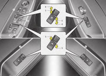
Fuse switch
OYDDMC2010
3. Pull the suspected fuse straight out. Use the removal tool provided in the engine compartment fuse panel.4. Check the removed fuse; replace it
if it is blown.
5. Push in a new fuse of the same rating, and make sure it fits tightly in the clips.
If it fits loosely, consult an authorized Kia dealer. If you do not have a spare, use a fuse of the same rating from a circuit you may not need for operating the vehicle, such as the cigarette lighter fuse.
OYDDMC2040
Your vehicle is equipped with a fuse switch to prevent battery discharge if your vehicle is parked without being operated for prolonged periods. Use the following procedures before parking the vehicle for prolonged periods. 1. Turn off the engine. 2. Turn off the headlights and tail
lights.
3. Open the driver’s side panel cover and move the fuse switch up to the OFF position.
7 63
YDM USA 7.QXP 5/1/2016 1:24 PM Page 64
Maintenance
✽✽ NOTICE • If the fuse switch is in the OFF the warning chime, position, audio, clock and interior lamps, etc., will not operate. Some items must be reset after replacement. Refer to “Battery” in this chapter. • Even when the fuse switch is in the OFF position, the battery can still be discharged by operation of the headlights or other electrical devices.
64
3. Check the removed fuse; replace it if it is blown. To remove or insert the fuse, use the fuse puller in the engine compartment fuse panel.
4. Push in a new fuse of the same rating, and make sure it fits tightly in the clips. If it fits loosely, consult an authorized Kia dealer.
CAUTION - Fuse panel
covers
After checking the fuse panel in the engine compartment, securely install the fuse panel cover. If not, electrical failures may occur from water contact.
Engine compartment fuse replacement
OYDDMC2011
1.Turn the ignition switch and allother switches off.
2.Remove the fuse panel cover by pressing the tab and pulling the cover up. When the blade type fuse is dis- connected, remove it by using the clip designed for changing fuses located in the engine room fuse box. Upon removal, securely insert reserve fuse of equal quantity.
YDM USA 7.QXP 5/1/2016 1:24 PM Page 65
Maintenance
Main fuse
Multi fuse
CAUTION
Visually inspect the battery cap to ensure it is securely closed.If the battery cap is not securely closed, moisture may enter the system and damage the electri- cal components.
OMD070021
If the main fuse is blown, it must be removed as follows: 1. Turn off the engine. 2. Disconnect the negative battery
cable.
3. Remove the nuts shown in the pic-
ture above.
4. Replace the fuse with a new one
of the same rating.
5. Reinstall in the reverse order of
removal.
OMD070022
If the multi fuse is blown, it must be removed as follows: 1. Remove the fuse panel in the
engine compartment.
2. Remove the nuts shown in the pic-
ture above.
3. Replace the fuse with a new one
of the same rating.
4. Reinstall in the reverse order of
removal.
7 65
YDM USA 7.QXP 5/1/2016 1:24 PM Page 66
Maintenance
Fuse/relay panel description
OYDDMC2012
Inside the fuse/relay panel covers, you can find the fuse/relay label describing fuse/relay name and capacity.
✽✽ NOTICE Not all fuse panel descriptions in this manual may be applicable to your vehicle. It is accurate at the time of printing. When you inspect the fuse panel in your vehicle, refer to the fuse panel label. ✽✽ NOTICE The actual fuse/relay panel label may differ depending on equip- ment/options. 66
OYDNMC5014
YDM USA 7.QXP 5/1/2016 1:25 PM Page 67
Engine compartment fuse panel
OYDDMC2013
✽✽ NOTICE Not all fuse panel descriptions in this manual may be applicable to your vehicle. It is accurate at the time of printing. When you inspect the fuse panel in your vehicle, refer to the fuse panel label.
Maintenance
OYDM076074
7 67
YDM USA 7.QXP 5/1/2016 1:25 PM Page 68
Maintenance
Engine room (Battery terminal cover)
OYDNMC2059
✽✽ NOTICE Not all fuse panel descriptions in this manual may be applicable to your vehicle. It is accurate at the time of printing. When you inspect the fuse panel in your vehicle, refer to the fuse panel label.
68
OYDM076075
YDM USA 7.QXP 5/1/2016 1:25 PM Page 69
Maintenance
Instrument panel fuse panel
Fuse Name P/SEAT DRV SPARE 4 P/WDW RH
TRUNK
P/WDW LH DR LOCK SPARE 3
POWER OUTLET 1
S/HEATER RR
MODULE 8 SPARE 2 MODULE 9
MODULE 1
A/CON
MODULE 5
HTD MIRR
INTERIOR LAMP
MODULE 6
PDM 2
SUNROOF
Fuse rating
Circuit Protected
30A 25A 25A 10A 25A 20A 20A 20A 20A 10A 7.5A 15A
10A
7.5A
7.5A
10A
7.5A
7.5A 7.5A 20A
Driver IMS Module, Driver Seat Manual Switch Smart Junction Block (Power Window RH Relay), Passenger Safety Power Window Module Smart Junction Box (Trunk Relay) Smart Junction Block (Power Window LH Relay), Driver Safety Power Window Module Smart Junction Block (Door Lock Relay, Door Unlock Relay), ICM Relay Box (Two Turn Unlock Relay) Cigarette Lighter & Power Outlet (Cigarette Lighter) Rear Seat Warmer LH/RH BCM, Smart Key Control Module Driver/Passenger Smart Key Outside Handle, Driver/Passenger Power Outside Handle Smart Key Control Module, BCM, Digital Clock, Audio, A/V & Navigation Head Unit, Power Outside Mirror Switch A/C Control Module, Cluster Ionizer, E/R Junction Block (Blower Relay, GSL PTC Heater Relay) Driver/Passenger Seat Warmer Module, Driver Passenger Air Ventilation Seat Control Module, Rear Seat Warmer LH/RH, Sunroof ECM/PCM, A/C Control Module, Driver/Passenger Power Outside Mirror Trunk Room Lamp, Glove Box Lamp, Vanity Lamp LH/RH, Room Lamp, Overhead Console Lamp, Ignition Key ILL. & Door Warning Switch, Luggage Lamp Key Solenoid [With Smart Key] Smart Key Control Module [W/O Smart Key] Immobilizer Module Sunroof
7 69
YDM USA 7.QXP 5/1/2016 1:25 PM Page 70
Maintenance
Fuse Name
Fuse rating
Circuit Protected
MODULE 2
10A
HTD STRG
IG 1
WIPER FRT
MULTIMEDIA 2
MEMORY
MODULE 7
PDM 3
MDPSMODULE 3
START
MULTIMEDIA 1
BRAKE SWITCHPDM 1
POWER OUTLET FRT
A/BAG IND
MODULE 4
A/BAG
15A 20A 25A 7.5A
7.5A
10A 7.5A 7.5A 7.5A
7.5A
15A 10A 20A 20A 7.5A
10A
15A
Electro Chromic Mirror, Multipurpose Check Connector, A/C Control Module, Driver CCS Switch, Driver/Passenger Air Ventilation Seat Control Module, Driver/Passenger Seat Warmer Module, Driver IMS Module, A/V & Navigation Head Unit, ATM Lever Indicator, Rear Seat Warmer LH/RH, Rear Power Window Switch LH/RH, Rear Seat Warmer LH/RH, Audio, Dynamic Bending Light Module, Console Switch LH/RH Steering Wheel Heater W/O Smart Key : E/R Junction Block (Fuse - TCU1, ECU 3, ABS 3) Wiper Motor, E/R Junction Block (Wiper Relay), Multifunction Switch (Wiper) Driver IMS Module, BCM, Tire Pressure Monitoring Module, Auto Light & Photo Sensor, Instrument Cluster, Data Link Connector, Digital Clock, A/C Control Module, Electro Chromic Mirror, ICM Relay Box (Turn Signal Lamp Sound Relay, Folding Relay, Unfolding Relay) [With Smart Key] Smart Key Control Module [W/O Smart Key] Immobilizer Module MDPS Unit Instrument Cluster [With Burglar Alarm & W/O Smart Key & W/O IMMO.] ICM Relay Box (Burglar Alarm Relay) [W/O Burglar Alarm or With Smart Key or With IMMO.] Transaxle Range Switch, Ignition Lock Switch Audio, A/V & Navigation Head Unit Stop Lamp Switch, Smart Key Control Module Smart Key Control Module Cigarette Lighter & Power Outlet (Power Outlet) Instrument Cluster (Air Bag IND.) Crash Pad Switch, Tire Pressure Monitoring Module, Stop Lamp Switch, Digital Clock, BCM, Blind Spot Detection Radar LH/RH, MDPS Unit, AEB Module, Sport Mode Switch, AEB Radar SRS Control Module, Weight Classification Module
70
YDM USA 7.QXP 5/1/2016 1:25 PM Page 71
Maintenance
Engine compartment fuse panel
Fuse Name
Fuse rating
Circuit Protected
MULTI FUSE
MDPS
B+1
ABS 1 C/FAN RR HTD BLOWER
GSL PTC HEATER
B+2
B/UP LAMP
TCU 1 ABS 3 ECU 3
FUSE
A/CON SWITCH
WIPER FRT
B+3 ECU 6
GSL PTC HEATER
DEICER
STOP LAMP
80A
60A
40A 40A 40A 40A 60A
60A
10A
15A 10A 10A 10A 10A 50A 40A 50A 15A 10A
MDPS Unit Smart Junction Block (ARISU-LT IPS 1 (4CH), Fuse - MODULE6, MODULE7, MODULE9, P/WDW LH, P/WDW RH, TRUNK) ESC Module C/Fan Relay RR HTD Relay Blower Relay GSL PTC Heater Relay Smart Junction Block (ARISU-LT IPS 3 (4CH), ARISU-LT IPS 4 (4CH), IPS 5 (2CH), Fuse - PDM 1, P/SEAT DRV BRAKE SWITCH, S/HEATER RR) A/T,DCT : Electro Chromic Mirror, Audio, A/V & Navigation Head Unit, Rear Combination Lamp (In) LH/RH M/T : Back-Up Lamp Switch A/T : Transaxle Range Switch, DCT : Transaxle Range Switch, TCM ESC Module ECM/PCM, Vacuum Pump A/C Control Module, Blower Motor, Blower Relay, ECM/PCM, Blower Resistor ECM/PCM, Wiper Motor, E/R Junction Block (Wiper FRT Relay) Smart Junction Block (Leak Current Autocut Device, Fuse - PDM 2, DR LOCK, SUNROOF) EMS Block (Engine Control Relay, Fuse - ECU 4, A/CON, F/PUMP) GSL PTC HEATER RELAY ICM Relay Box (Front Deicer Relay) Stop Signal Electronic Module
7 71
YDM USA 7.QXP 5/1/2016 1:25 PM Page 72
Maintenance
FUSE
Fuse Name S/HEATER FRT
HORN ECU 5
IG 2
ABS 2
IG 1WIPER RR
TCU 3
TCU 2
TCU 4Fuse rating
Circuit Protected
20A 15A 15A
40A
40A 40A
15A
40A 20A 40A
Driver/Passenger Air Ventilation Seat Control Module, Driver/Passenger Seat Warmer Module Horn Relay, ICM Relay Box (Burglar Alarm Horn Relay) ECM/PCM W/O Smart Key : Ignition Switch, Start 1 Relay, With Smart Key : PDM 4 (IG2) Relay, Start 1
Relay ESC Module W/O Smart Key : Ignition Switch, With Smart Key : PDM 3 (IG1) Relay, PDM 2 (ACC) Relay Multifunction Switch, Rear Wiper Motor, ICM Relay Box (Rear Wiper Relay), Ignition Switch, PDM 4 (IG2) Relay TCM TCM TCM72
YDM USA 7.QXP 5/1/2016 1:25 PM Page 73
Fuse & Relay Box( NU 2.0L MPI/ NU 2.0 GDI)
Relay NO.
E41
E42
E43
E44
E45
E46
E47
E48
E49
E50
E52Relay Name
RR HTD RELAY WIPER RELAY GSL PTC RELAY
PDM 2 (ACC) RELAY
START 1 RELAY
PDM 3 (IG1) RELAY
C/FAN RELAY HORN RELAY
PDM 4 (IG2) RELAY
BLOWER RELAY C/FAN 2 RELAY
Junction Block (GAMMA 1.6L T-GDI)
Relay NO.
E41
E42
E43
E44
E45
E46
E47
E48
E49
E50
E52Relay Name
RR HTD RELAY WIPER RELAY GSL PTC RELAY
PDM 2 (ACC) RELAY
START 1 RELAY
PDM 3 (IG1) RELAY
C/FAN RELAY HORN RELAY
PDM 4 (IG2) RELAY
BLOWER RELAY C/FAN 2 RELAY
Type
PLUG MICRO PLUG MICRO PLUG MICRO PLUG MICRO PLUG MICRO PLUG MICRO
PLUG MINI
PLUG MICRO