- 2011 Jeep Wrangler Owners Manuals
- Jeep Wrangler Owners Manuals
- 2005 Jeep Wrangler Owners Manuals
- Jeep Wrangler Owners Manuals
- 2006 Jeep Wrangler Owners Manuals
- Jeep Wrangler Owners Manuals
- 2004 Jeep Wrangler Owners Manuals
- Jeep Wrangler Owners Manuals
- 2013 Jeep Wrangler Owners Manuals
- Jeep Wrangler Owners Manuals
- 2009 Jeep Wrangler Owners Manuals
- Jeep Wrangler Owners Manuals
- 2008 Jeep Wrangler Owners Manuals
- Jeep Wrangler Owners Manuals
- 2012 Jeep Wrangler Owners Manuals
- Jeep Wrangler Owners Manuals
- 2010 Jeep Wrangler Owners Manuals
- Jeep Wrangler Owners Manuals
- 2007 Jeep Wrangler Owners Manuals
- Jeep Wrangler Owners Manuals
- Download PDF Manual
-
The fold-down windshield and removable side bars on your vehicle are structural elements that can provide some protection in some accidents. The windshield also provides some protection against weather, road debris and intrusion of small branches and other objects. Do not drive your vehicle on-road with the windshield down and the side bars removed as you lose the protec- tion these structural elements can provide. If required for certain off-road uses, the side bars can be removed and the windshield folded down. However, the protection afforded by these features is then lost. If you remove the side bars and fold down the windshield, drive slowly and cautiously. It is recommended that the speed of the vehicle be limited to 10 mph (16 km/h), with low range operation preferred if you are driving off-road with the windshield folded down.
Raise the windshield and reinstall the side bars as soon as the task that required their removal is completed and before you return to on-road driving. Both you and your passenger should wear seat belts at all times, on-road and off-road, regardless of whether the windshield is raised or folded down. Outside rearview mirrors are mounted on the doors. If you choose to remove the doors, see your authorized dealer for a replacement cowl-mounted outside mirror. Federal law requires outside mirrors on vehicles for on-road use.
WARNING!
Carefully follow these warnings to help protect against personal injury: • Do not drive your vehicle on-road with the wind- shield down.
(Continued)
UNDERSTANDING THE FEATURES OF YOUR VEHICLE 287
WARNING! (Continued)
• Do not drive your vehicle unless the windshield is securely fastened, either up or down. • Eye protection, such as goggles, should be worn at all times when the windshield is down. • Be sure that you carefully follow the instructions for raising the windshield. Make sure that the folding windshield, windshield wipers, side bars, and all associated hardware and fasteners are cor- rectly and tightly assembled before driving your vehicle. Failure to follow these instructions may prevent your vehicle from providing you and your passengers protection in some accidents. • If you remove the doors, store them outside the vehicle. In the event of an accident, a loose door may cause personal injury.
288 UNDERSTANDING THE FEATURES OF YOUR VEHICLE Lowering The Windshield And Removing Side Bars
1. Lower the fabric top or remove the hard top following
the instructions in this manual.
NOTE: To assist in properly reinstalling side bars, mark the original locations prior to removing. 2. Remove the two top hex bolts (13 mm), and the one side hex bolt (13 mm) visible through the trim (Do not remove plastic corner trim, sun visor bolts, or sport bar covering).
3. Remove the sun visor. 4. Remove the A-pillar cap. 5. Disconnect microphone (if equipped with Uconnect™
phone).
6. Open the sport bar Velcro covering.
7. Remove the one hex bolt (13 mm) visible through the plastic trim on the bottom side of the side bar, one hex bolt (13 mm) on the side of the side bar, and one hex bolt (13 mm) on top of the side bar.
NOTE: Pull side bar out horizontally when removing.
UNDERSTANDING THE FEATURES OF YOUR VEHICLE 289
CAUTION!
Do not remove the head impact foam from the side bars, as damage to the foam may result.
NOTE: Store all of the mounting bolts in their original threaded holes and tighten for safekeeping. 8. Remove the side bar assembly, and reattach the sport
bar Velcro威 covering.
9. To safely store the side bars in your vehicle, use four cinch straps (available from your authorized dealer). Attach the straps through the slots located on the floor behind the folded rear seat at the front of the storage bin cover.
11. Remove the lower windshield plates by removing the six black round-headed Torx威 head screws (using a #40 Torx威 head driver) on each side of the base of the windshield.
290 UNDERSTANDING THE FEATURES OF YOUR VEHICLE
WARNING!
You or others could be injured if you carry the side bars loose in your vehicle. Remove the side bars from the vehicle or securely store them as described or they may cause personal injury if an accident occurs. See your authorized dealer for the cinch straps.
10. Remove the windshield wiper arms by first pulling the wiper away from the windshield and out to the “lock” position. Unsnap the wiper arm nut caps, and remove the retaining nuts. Lift the wiper arms off and store them in the center console or securely behind the rear seat.
NOTE: It may be necessary to use a battery terminal puller tool in order to separate the wiper arms from the shaft after the nuts have been removed.
12. Lower the windshield gently until it contacts the
rubber hood bumpers.
13. Secure the windshield by passing a cinch strap through the footman hoop on the center of the hood and on the center of the windshield frame. Tighten the strap to secure the windshield in place.
Raising The Windshield And Replacing Side Bars
1. Raise the windshield. 2. Loosely attach the rear of the side bar to the sport bar. Refer to Step 4 of “Lowering Windshield And Remov- ing Side Bars” earlier in this section.
UNDERSTANDING THE FEATURES OF YOUR VEHICLE 291
• Reattach the sport bar Velcro威 covering.
292 UNDERSTANDING THE FEATURES OF YOUR VEHICLE 3. Attach the front of the side bar to the windshield frame. • Install the top two hex bolts (13 mm) first, then the lower side hex bolt (13 mm). The lower side bolt will not align until the top two bolts are installed.
5. Install the lower windshield plates with the six black round-headed Torx威 head screws (using a #40 Torx威 head driver) on each side of the base of the wind- shield.
4. Tighten all side bar attachment bolts.
6. Reinstall the wiper arms.
REAR WINDOW FEATURES — HARD TOP ONLY
Rear Window Wiper/Washer — If Equipped A rotary switch on the center portion of the control lever (located on the right side of the steering column) controls the operation of the rear wiper/washer function.
UNDERSTANDING THE FEATURES OF YOUR VEHICLE 293
Rotate the switch upward to the first detent position for rear wiper operation. Rotate the switch upward past the first detent to activate the rear washer. The washer pump and the wiper will continue to operate as long as the switch is held. Upon release, the wiper will cycle two to three times before returning to the set position. If the rear wiper is operating when the ignition is turned to the LOCK position, the wiper will automatically return to the “Park” position. When the vehicle is restarted, the wiper will resume function at whichever position the switch is set at.Rear Wiper/Washer Control
294 UNDERSTANDING THE FEATURES OF YOUR VEHICLE Rear Window Defroster — If Equipped
The rear window defroster button is located on the bottom right-side of the blower control knob. Press this button to turn on the rear window defroster. An indicator in the button will illuminate when the rear window defroster is on. The rear window defroster automatically turns off after approximately 10 minutes. For an additional five minutes of operation, press the button a second time. NOTE: To prevent excessive battery drain, use the rear window defroster only when the engine is operating.
CAUTION!
Failure to follow these cautions can cause damage to the heating elements: • Use care when washing the inside of the rear window. Do not use abrasive window cleaners on the interior surface of the window. Use a soft cloth and a mild washing solution, wiping parallel to the heating elements. Labels can be peeled off after soaking with warm water. • Do not use scrapers, sharp instruments, or abrasive window cleaners on the interior surface of the window. • Keep all objects a safe distance from the window.
UNDERSTANDING YOUR INSTRUMENT PANEL
CONTENTS 䡵 INSTRUMENT PANEL FEATURES . . . . . . . . ..298
䡵 INSTRUMENT CLUSTER . . . . . . . . . . . . . . . ..299
䡵 INSTRUMENT CLUSTER DESCRIPTIONS . . . ..300
䡵 COMPASS AND TRIP COMPUTER — IFEQUIPPED . . . . . . . . . . . . . . . . . . . . . . . . . . .315
▫ Control Buttons . . . . . . . . . . . . . . . . . . . . . . .316
▫ Compass/Temperature Display . . . . . . . . . . ..317
▫ Trip Conditions . . . . . . . . . . . . . . . . . . . . . . .320䡵 ELECTRONIC VEHICLE INFORMATION
CENTER (EVIC) — IF EQUIPPED . . . . . . . . . ..321
▫ Electronic Vehicle Information Center (EVIC)
Displays . . . . . . . . . . . . . . . . . . . . . . . . . . . .324
▫ Oil Change Required . . . . . . . . . . . . . . . . ..325
▫ EVIC Main Menu . . . . . . . . . . . . . . . . . . . ..326
▫ Compass Display / ECO (Fuel Saver Mode)— If Equipped . . . . . . . . . . . . . . . . . . . . . . .326
▫ Average Fuel Economy. . . . . . . . . . . . . . . . ..329
▫ Distance To Empty (DTE) . . . . . . . . . . . . . . ..330
▫ Elapsed Time . . . . . . . . . . . . . . . . . . . . . . . .330
▫ EVIC Units Selection (UNITS IN Display) . . . .330296 UNDERSTANDING YOUR INSTRUMENT PANEL
▫ System Status . . . . . . . . . . . . . . . . . . . . . . . .331
▫ Personal Settings (Customer-ProgrammableFeatures)
. . . . . . . . . . . . . . . . . . . . . . . . . . .331
䡵 MEDIA CENTER 230 (REQ) — AM/FM STEREO
RADIO AND 6–DISC CD/DVD CHANGER (MP3/WMA AUX JACK) . . . . . . . . . . . . . . . ..335
▫ Operating Instructions - Radio Mode. . . . . . ..335
▫ Operation Instructions - (DISC MODE for CDand MP3/WMA Audio Play, DVD-VIDEO) . . .344
▫ Notes On Playing MP3/WMA Files. . . . . . . ..346
▫ LIST Button (DISC Mode for MP3/WMA Play) . .348
▫ INFO Button (DISC Mode for MP3/WMA Play) . .349
▫ Uconnect™ Multimedia (Satellite Radio) — IfEquipped . . . . . . . . . . . . . . . . . . . . . . . . . . .377
䡵 MEDIA CENTER 730N/430/430N (RHR/RER/
RBZ/RHB) CD/DVD/HDD/NAV — IF EQUIPPED . . . . . . . . . . . . . . . . . . . . . . .355
▫ Operating Instructions (Voice Command System)— If Equipped . . . . . . . . . . . . . . . . . . . . . . .355
▫ Operating Instructions (Uconnect™ Phone)
— If Equipped . . . . . . . . . . . . . . . . . . . . . . .355
䡵 MEDIA CENTER 130 (SALES CODE RES) . . . ..356
▫ Operating Instructions — Radio Mode. . . . . ..356
▫ Operation Instructions — CD MODE ForCD And MP3 Audio Play . . . . . . . . . . . . . . ..359
▫ Notes on Playing MP3 Files . . . . . . . . . . . . ..362
▫ Operation Instructions - Auxiliary Mode . . . ..364䡵 MEDIA CENTER 130 WITH SATELLITE
RADIO (SALES CODE RES+RSC) . . . . . . . . . ..365
▫ Operating Instructions — Radio Mode. . . . . ..365
▫ Operation Instructions — CD MODE forCD and MP3 Audio Play . . . . . . . . . . . . . . ..371
▫ Notes On Playing MP3 Files . . . . . . . . . . . . ..374
▫ LIST Button (CD Mode for MP3 Play) . . . . . ..376
▫ INFO Button (CD Mode for MP3 Play) . . . . ..376
▫ Uconnect™ Multimedia (Satellite Radio)— If Equipped . . . . . . . . . . . . . . . . . . . . . . .377
䡵 iPod威/USB/MP3 CONTROL — IF EQUIPPED . .382▫ Connecting The iPod威 Or External USB
Device . . . . . . . . . . . . . . . . . . . . . . . . . . . . .382
▫ Using This Feature. . . . . . . . . . . . . . . . . . . ..383
▫ Controlling The iPod威 Or External USB DeviceUsing Radio Buttons . . . . . . . . . . . . . . . . . ..384
UNDERSTANDING YOUR INSTRUMENT PANEL 297
▫ Play Mode . . . . . . . . . . . . . . . . . . . . . . . . . .384
▫ List Or Browse Mode . . . . . . . . . . . . . . . . . ..386
▫ Bluetooth Streaming Audio (BTSA) . . . . . . . ..388
䡵 STEERING WHEEL AUDIO CONTROLS . . . . ..389
▫ Radio Operation . . . . . . . . . . . . . . . . . . . . . .390
▫ CD Player . . . . . . . . . . . . . . . . . . . . . . . . . . .390
䡵 CD/DVD DISC MAINTENANCE . . . . . . . . . ..390
䡵 RADIO OPERATION AND MOBILE PHONES . .391
䡵 CLIMATE CONTROLS . . . . . . . . . . . . . . . . . ..391
▫ Manual Heating And Air Conditioning . . . . ..392
▫ Automatic Temperature Control (ATC)— If Equipped . . . . . . . . . . . . . . . . . . . . . . .396
▫ Operating Tips . . . . . . . . . . . . . . . . . . . . . . .401298 UNDERSTANDING YOUR INSTRUMENT PANEL INSTRUMENT PANEL FEATURES
1 — Air Outlet 2 — Instrument Cluster 3 — Radio 4 — Assist Handle 5 — Glove Compartment 6 — Power Window Switches
7 — Climate Controls 8 — Power Outlet 9 — Lower Switch Bank 10 — Power Mirror Switch — If Equipped 11 — Horn
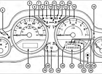
INSTRUMENT CLUSTER
UNDERSTANDING YOUR INSTRUMENT PANEL 299
300 UNDERSTANDING YOUR INSTRUMENT PANEL INSTRUMENT CLUSTER DESCRIPTIONS 1. Fuel Gauge The pointer shows the level of fuel in the fuel tank when the ignition switch is in the ON/RUN position. 2. Charging System Light
This light shows the status of the electrical charg- ing system. The light should come on when the ignition switch is first turned to ON/RUN, and remain on briefly as a bulb check. If the light stays on or comes on while driving, turn off some of the vehicle’s non- essential electrical devices or increase engine speed (if at idle). If the charging system light remains on, it means that the vehicle is experiencing a problem with the charging system. Obtain SERVICE IMMEDIATELY. See an authorized dealer. If jump starting is required, refer to “Jump Starting Procedures” in “What To Do In Emergencies”.
3. Front Fog Light Indicator — If Equipped
This indicator will illuminate when the front fog lights are on.
4. Low Fuel Warning Light
When the fuel level reaches approximately 2.8 gal (10.6L) this light will turn on and a single chime
will sound. 5. Speedometer Indicates vehicle speed. 6. Front Axle Lock Indicator — If Equipped
Indicates when the front axle lock has been activated.
UNDERSTANDING YOUR INSTRUMENT PANEL 301
7. Seat Belt Reminder Light
9. Oil Pressure Warning Light
When the ignition switch is first turned to ON/ RUN, this light will turn on for four to eight seconds as a bulb check. During the bulb check, if the driver’s seat belt is unbuckled, a chime will sound. After the bulb check or when driving, if the driver seat belt remains unbuckled, the Seat Belt Reminder Light will flash or remain on continuously. Refer to “Occupant Restraints” in “Things To Know Before Starting Your Vehicle” for further information. 8. Turn Signal Indicators
The left or right arrow will flash with the corre- sponding exterior turn signal lights when the turn signal lever is operated. A chime will sound if the vehicle is driven more than 1 mile (1.6 km) with either turn signal on. NOTE: If either indicator flashes at a rapid rate, check for a defective outside light bulb.
This light indicates low engine oil pressure. The light should turn on momentarily when the engine is started; if the bulb does not come on, have the system checked by an authorized dealer. If the light turns on while driving, stop the vehicle and shut off the engine as soon as possible. A chime will sound when this light turns on. Do not operate the vehicle until the cause is corrected. This light does not indicate how much oil is in the engine. The engine oil level must be checked under the hood. 10. High Beam Indicator
This indicator shows that the high beam head- lights are on. Push the multifunction control lever away from you to switch the headlights to high beam. Pull the lever toward you to switch the headlights back to low beam. If the driver’s door is open, and the headlights or park lights are left on, the high beam indicator light will remain illuminated and a chime will sound.
302 UNDERSTANDING YOUR INSTRUMENT PANEL 11. Brake Warning Light
This light monitors various brake functions, including brake fluid level and parking brake application. If the brake light turns on it may indicate that the parking brake is applied, that the brake fluid level is low, or that there is a problem with the anti-lock brake system reservoir. If the light remains on when the parking brake has been disengaged, and the fluid level is at the full mark on the master cylinder reservoir, it indicates a possible brake hydraulic system malfunction or that a problem with the Brake Booster has been detected by the Anti-Lock Brake System (ABS) / Electronic Stability Control (ESC) system. In this case, the light will remain on until the condition has been corrected. If the problem is related to the brake booster, the ABS pump will run when applying the brake and a brake pedal pulsation may be felt during each stop.
The dual brake system provides a reserve braking capac- ity in the event of a failure to a portion of the hydraulic system. A leak in either half of the dual brake system is indicated by the Brake Warning Light, which will turn on when the brake fluid level in the master cylinder has dropped below a specified level. The light will remain on until the cause is corrected. NOTE: The light may flash momentarily during sharp cornering maneuvers, which change fluid level condi- tions. The vehicle should have service performed, and the brake fluid level checked. If brake failure is indicated, immediate repair is necessary.
WARNING!
Driving a vehicle with the red brake light on is dangerous. Part of the brake system may have failed.
(Continued)
WARNING! (Continued)
It will take longer to stop the vehicle. You could have a collision. Have the vehicle checked immediately.
Vehicles equipped with the Anti-Lock Brake System (ABS), are also equipped with Electronic Brake Force Distribution (EBD). In the event of an EBD failure, the Brake Warning Light will turn on along with the ABS Light. Immediate repair to the ABS system is required. Operation of the Brake Warning Light can be checked by turning the ignition switch from the OFF position to the ON/RUN position. The light should illuminate for ap- proximately two seconds. The light should then turn off unless the parking brake is applied or a brake fault is detected. If the light does not illuminate, have the light inspected by an authorized dealer.
UNDERSTANDING YOUR INSTRUMENT PANEL 303
The light also will turn on when the parking brake is applied with the ignition switch in the ON/RUN posi- tion. NOTE: This light shows only that the parking brake is applied. It does not show the degree of brake application. 12. Anti-Lock Brake (ABS) LightAfter the ignition is turned on, the Anti-Lock Brake System (ABS) light illuminates to indicate function check at vehicle start-up. If the light remains on after start-up or comes on and stays on at road speeds, it may indicate that the ABS has detected a malfunction or has become inoperative. The system reverts to standard non-anti-lock brakes. If both the Brake Warning Light and the ABS Warning Light are on, see an authorized dealer immediately. Refer to “Anti-Lock Brake System” in “Starting And Operating”.
304 UNDERSTANDING YOUR INSTRUMENT PANEL 13. Air Bag Warning Light
This light will turn on for four to eight seconds as a bulb check when the ignition switch is first turned to ON/RUN. If the light is either not on during starting, stays on, or turns on while driving, have the system inspected at an authorized dealer as soon as possible. Refer to “Occupant Restraints” in “Things To Know Before Starting Your Vehicle” for further information. 14. Rear Axle Lock Indicator — If Equipped
This light indicates when the rear axle lock has been activated.
15. Tachometer Indicates the engine speed in revolutions per minute (RPM x 1000).
CAUTION!
Do not operate the engine with the tachometer pointer in the red area. Engine damage will occur.
16. Coolant Temperature Warning Light
This light warns of an overheated engine condition. If the light turns on while driving, safely pull over and stop the vehicle. If the A/C system is on, turn it off. Also, shift the transmission into NEUTRAL and idle the vehicle. If the temperature reading does not return to normal, turn the engine off immediately and call for service. NOTE: As the coolant temperature gauge approaches ⬙H,⬙ this indicator will illuminate and a single chime will sound. Further overheating will cause the temperature
gauge to pass ⬙H.⬙ In this case, a continuous chime will sound, until the engine is allowed to cool or the 4 minutes duration is expired, whichever come first. 17. Vehicle Security Light — If Equipped
This light will flash at a fast rate for approxi- mately 15 seconds, when the vehicle security alarm is arming, and then will flash slowly until the vehicle is disarmed.
18. Temperature Gauge The temperature gauge shows engine coolant tempera- ture. Any reading within the normal range indicates that the engine cooling system is operating satisfactorily. The gauge pointer will likely indicate a higher tempera- ture when driving in hot weather, up mountain grades, or when towing a trailer. It should not be allowed to exceed the upper limits of the normal operating range.
UNDERSTANDING YOUR INSTRUMENT PANEL 305
CAUTION!
Driving with a hot engine cooling system could damage your vehicle. If the temperature gauge reads “H” pull over and stop the vehicle. Idle the vehicle with the air conditioner turned off until the pointer drops back into the normal range. If the pointer remains on the “H” and you hear continuous chimes, turn the engine off immediately and call an autho- rized dealer for service.
WARNING!
A hot engine cooling system is dangerous. You or others could be badly burned by steam or boiling coolant. You may want to call an authorized dealer for service if your vehicle overheats. If you decide to
(Continued)
306 UNDERSTANDING YOUR INSTRUMENT PANEL
WARNING! (Continued)
look under the hood yourself, see “Maintaining Your Vehicle”. Follow the warnings under the Cooling System Pressure Cap paragraph.
19. Cruise Indicator
This indicator shows when the electronic speed control system is turned on.
20. 4WD Indicator Light — If Equipped
This light alerts the driver that the vehicle is in the four-wheel drive mode, and the front and rear driveshafts are mechanically locked to- gether forcing the front and rear wheels to
rotate at the same speed.
21. Odometer/Trip Odometer/ECO (Fuel Saver Indica- tor) Button Press this button to change the display from odometer to either of the two trip odometer settings or the “ECO” display. Trip A or Trip B will appear when in the trip odometer mode. Press and hold the button for two seconds to reset the trip odometer to 0 miles or kilome- ters. The odometer must be in trip mode to reset. 22. Shift Lever Indicator The Shift Lever Indicator is self-contained within the instrument cluster. It displays the gear position of the automatic transmission. 23. Tire Pressure Monitoring Telltale Light
Each tire, including the spare (if provided), should be checked monthly when cold and in- flated to the inflation pressure recommended by
the vehicle manufacturer on the vehicle placard or tire inflation pressure label. (If your vehicle has tires of a different size than the size indicated on the vehicle placard or tire inflation pressure label, you should determine the proper tire inflation pressure for those tires.) As an added safety feature, your vehicle has been equipped with a Tire Pressure Monitoring System (TPMS) that illuminates a low tire pressure telltale when one or more of your tires is significantly under-inflated. Accordingly, when the low tire pressure telltale illumi- nates, you should stop and check your tires as soon as possible, and inflate them to the proper pressure. Driving on a significantly under-inflated tire causes the tire to overheat and can lead to tire failure. Under-inflation also reduces fuel efficiency and tire tread life, and may affect the vehicle’s handling and stopping ability.
UNDERSTANDING YOUR INSTRUMENT PANEL 307
Please note that the TPMS is not a substitute for proper tire maintenance, and it is the driver’s responsibility to maintain correct tire pressure, even if under-inflation has not reached the level to trigger illumination of the TPMS low tire pressure telltale. Your vehicle has also been equipped with a TPMS malfunction indicator to indicate when the system is not operating properly. The TPMS malfunction indicator is combined with the low tire pressure telltale. When the system detects a malfunction, the telltale will flash for approximately one minute and then remain continuously illuminated. This sequence will continue upon subse- quent vehicle start-ups as long as the malfunction exists. When the malfunction indicator is illuminated, the sys- tem may not be able to detect or signal low tire pressure as intended. TPMS malfunctions may occur for a variety of reasons, including the installation of replacement or alternate tires or wheels on the vehicle that prevent the308 UNDERSTANDING YOUR INSTRUMENT PANEL TPMS from functioning properly. Always check the TPMS malfunction telltale after replacing one or more tires or wheels on your vehicle, to ensure that the replacement or alternate tires and wheels allow the TPMS to continue to function properly.
CAUTION!
The TPMS has been optimized for the original equipment tires and wheels. TPMS pressures and warning have been established for the tire size equipped on your vehicle. Undesirable system opera- tion or sensor damage may result when using re- placement equipment that is not of the same size, type, and/or style. Aftermarket wheels can cause sensor damage. Do not use tire sealant from a can or balance beads if your vehicle is equipped with a TPMS, as damage to the sensors may result.
24. Odometer / Trip Odometer Display Area The odometer display shows the total distance the vehicle has been driven. The trip odometer shows individual trip mileage. Refer to “Odometer/Trip Odometer/ECO (Fuel Saver Indicator) Button” for additional information. U.S. Federal regulations require that upon transfer of vehicle ownership, the seller certify to the purchaser the correct mileage that the vehicle has been driven. If your odometer needs to be repaired or serviced, the repair technician should leave the odometer reading the same as it was before the repair or service. If s/he cannot do so, then the odometer must be set at zero, and a sticker must be placed in the door jamb stating what the mileage was before the repair or service. It is a good idea for you to make a record of the odometer reading before the repair/ service, so that you can be sure that it is properly reset, or that the door jamb sticker is accurate if the odometer must be reset at zero.
Vehicle Odometer Messages When the appropriate conditions exist, the following odometer messages will display:
ECO . . . . . . . . . . . . . . . . . . . . . Fuel Saver Indicator . . . . . . . . . . . . . . . . . . . . . . . . . . . . Door Ajar door gATE . . . . . . . . . . . . . . . . . . . . . . . Swing Gate Ajar LoW tirE . . . . . . . . . . . . . . . . . . . Low Tire Pressure HOTOIL . . . . . . . . . . . Transmission Oil Temperature Above Normal Limits gASCAP . . . . . . . . . . . . . . . . . . . . . . Fuel Cap Fault noFUSE . . . . . . . . . . . . . . . . . . . . . . . . . Fuse Fault CHAngE OIL . . . . . . . . . . . . . . Oil Change Required
UNDERSTANDING YOUR INSTRUMENT PANEL 309
ECO (Fuel Saver Indicator) — If Equipped The ECO indicator will illuminate when you are driving in a fuel efficient manner and can be used to modify driving habits in order to increase fuel economy. LoW tirE When the appropriate condition exists, the odometer display will toggle between LoW and tirE for three cycles. “HOTOIL” Transmission Temperature Warning Message The “HOTOIL” cluster message will appear in the odom- eter accompanied with a chime to indicate that there is excessive transmission fluid temperature that might oc- cur with severe usage such as trailer towing. It may also occur when operating the vehicle in a high torque converter slip condition, such as 4-wheel drive operation
310 UNDERSTANDING YOUR INSTRUMENT PANEL (e.g., snow plowing, off-road operation). If this “HOT- OIL” message turns on, stop the vehicle and run the engine at idle or faster with the transmission in NEU- TRAL until the message turns off.
CAUTION!
Continuous driving with the Transmission Tempera- ture “HOTOIL” Warning message illuminated will eventually cause severe transmission damage or transmission failure.
WARNING!
If the Transmission Temperature “HOTOIL” Warn- ing message is illuminated and you continue operat- ing the vehicle, in some circumstances you could cause the fluid to boil over, come in contact with hot engine or exhaust components and cause a fire.
gASCAP If the vehicle diagnostic system determines that the fuel filler cap is loose, improperly installed, or damaged, a “gASCAP” message will display in the odometer display area. Tighten the fuel filler cap properly and press the TRIP ODOMETER button to turn off the message. If the problem continues, the message will appear the next time the vehicle is started. noFUSE If the vehicle diagnostic system determines that the Ignition Off Draw (IOD) fuse is improperly installed, or damaged, a “noFUSE” message will display in the odom- eter display area. For further information on fuses and fuse locations refer to “Fuses” in “Maintaining Your Vehicle”.
CHAngE OIL Message Your vehicle is equipped with an engine oil change indicator system. The “CHANgE OIL” message will flash in the instrument cluster odometer for approximately 12 seconds after a single chime has sounded to indicate the next scheduled oil change interval. The engine oil change indicator system is duty-cycle based, which means the engine oil change interval may fluctuate dependent upon your personal driving style. Unless reset, this message will continue to display each time you turn the ignition switch to the ON/RUN position. To turn off the message temporarily, press and release the Trip Odometer button on the instrument cluster. To reset the oil change indicator system (after performing the scheduled maintenance), refer to the following procedure: Turn the ignition switch to the ON/RUN position (do not start the engine).
UNDERSTANDING YOUR INSTRUMENT PANEL 311
Fully depress the accelerator pedal slowly three times within 10 seconds. Turn the ignition switch to the OFF/LOCK position. NOTE: If the indicator message illuminates when you start the vehicle, the oil change indicator system did not reset. If necessary, repeat this procedure. 25. Malfunction Indicator Light (MIL)The Malfunction Indicator Light (MIL) is a part of an Onboard Diagnostic System called OBD II that monitors engine and automatic transmission con- trol systems. The light will illuminate when the ignition is in the ON position before engine start. If the bulb does not come on when turning the key from OFF to ON/ RUN, have the condition checked promptly.
312 UNDERSTANDING YOUR INSTRUMENT PANEL Certain conditions, such as a loose or missing gas cap, poor quality fuel, etc., may illuminate the light after engine start. The vehicle should be serviced if the light stays on through several typical driving styles. In most situations, the vehicle will drive normally and will not require towing. When the engine is running, the MIL may flash to alert serious conditions that could lead to immediate loss of power or severe catalytic converter damage. The vehicle should be serviced as soon as possible if this occurs.
CAUTION!
Prolonged driving with the MIL on could cause damage to the engine control system. It also could affect fuel economy and drivability. If the MIL is flashing, severe catalytic converter damage and power loss will soon occur. Immediate service is required.
WARNING!
A malfunctioning catalytic converter, as referenced above, can reach higher temperatures than in normal operating conditions. This can cause a fire if you drive slowly or park over flammable substances such as dry plants, wood, cardboard, etc. This could result in death or serious injury to the driver, occupants or others.
26. Electronic Stability Control Malfunction Indicator Light — If Equipped
(ESC) Activation/
The “ESC Activation/Malfunction Indicator Light” in the instrument cluster will come on when the ignition switch is turned to the ON/RUN position. It should go out with the
engine running. If the “ESC Activation/Malfunction In- dicator Light” comes on continuously with the engine running, a malfunction has been detected in the ESC system. If this light remains on after several ignition cycles, and the vehicle has been driven several miles (kilometers) at speeds greater than 30 mph (48 km/h), see your authorized dealer as soon as possible to have the problem diagnosed and corrected. NOTE: The “ESC Off Indicator Light” and the “ESC Activation/ Malfunction Indicator Light” come on momentarily each time the ignition switch is turned to ON/RUN. Each time the ignition is turned to ON/RUN, the ESC system will be ON, even if it was turned off previously.
UNDERSTANDING YOUR INSTRUMENT PANEL 313
The ESC system will make buzzing or clicking sounds when it is active. This is normal; the sounds will stop when ESC becomes inactive following the maneuver that caused the ESC activation.WARNING!
The Electronic Stability Control (ESC) cannot pre- vent the natural laws of physics from acting on the vehicle, nor can it increase the traction afforded by prevailing road conditions. ESC cannot prevent acci- dents, including those resulting from excessive speed in turns, driving on very slippery surfaces, or hydro- planing. The capabilities of an ESC-equipped vehicle must never be exploited in a reckless or dangerous manner which could jeopardize the user’s safety or the safety of others.
314 UNDERSTANDING YOUR INSTRUMENT PANEL 27. Sway Bar Indicator Light — If Equipped
This indicator will illuminate when the front sway bar is disconnected.
28. Electronic Stability Control (ESC) OFF Indicator Light — If Equipped
This light indicates the Electronic Stability Con- trol (ESC) is off.
29. Electronic Throttle Control (ETC) Light
This light informs you of a problem with the Electronic Throttle Control (ETC) system. If a problem is detected while the engine is run- ning, the light will either stay on or flash depending on
the nature of the problem. Cycle the ignition key when the vehicle is safely and completely stopped and the shift lever is placed in the PARK position. The light should turn off. If the light remains on with the engine running, your vehicle will usually be drivable; however, see an authorized dealer for service as soon as possible. If the light continues to flash when the engine is running, immediate service is required and you may experience reduced performance, an elevated/rough idle, or engine stall and your vehicle may require towing. The light will come on when the ignition is first turned to ON/RUN and remain on briefly as a bulb check. If the light does not come on during starting, have the system checked by an authorized dealer.
30. Electronic Vehicle Information Center (EVIC) Display/ Compass Mini-Trip Computer Display — If Equipped When the appropriate conditions exist, this display shows the Electronic Vehicle Information Center (EVIC) messages. For further information, refer to “Electronic Vehicle Information Center”. When the appropriate conditions exist, this display shows the Mini-Trip Computer messages. Refer to “Mini- Trip Computer” for further information.
UNDERSTANDING YOUR INSTRUMENT PANEL 315
COMPASS AND TRIP COMPUTER — IF EQUIPPED The Compass/Trip Computer a driver- interactive display (displays information on outside temperature, compass direction, and trip information). It is located on the lower left part of the cluster below the speedometer.features
Compass Display
316 UNDERSTANDING YOUR INSTRUMENT PANEL Control Buttons The Compass/Temperature control buttons are located on the left spoke of the steering wheel.
Mini-Trip Control Buttons
Press and release the STEP button on the steering wheel to access the options in the Compass display.
NOTE: The system will display the last known outside temperature when starting the vehicle and may need to be driven several minutes before the updated tempera- ture is displayed. Engine temperature can also affect the displayed temperature; therefore, temperature readings are not updated when the vehicle is not moving. The following displays can be reset or changed: • Compass/Temperature • AVG ECO (changes to present fuel economy) • ET (will reset display) • DTE (distance to empty) These messages can be cycled through by pressing the STEP button on the steering wheel. To reset the AVG ECO or ET, press and hold the STEP button for approximately three seconds.
Compass/Temperature Display
NOTE: If the vehicle is equipped with a Chrysler Uconnect™ gps (Navigation Radio), the NAV system will provide the compass direction, and the variance and calibration menus will be unavailable. The compass will perform accurately, based on GPS signals instead of the Earth’s magnetic field. Compass Variance Compass Variance is the difference between Magnetic North and Geographic North. To compensate for the differences, the variance should be set for the zone where the vehicle is driven, per the zone map. Once properly set, the compass will automatically compensate for the differences and provide the most accurate compass head- ing.
UNDERSTANDING YOUR INSTRUMENT PANEL 317
Compass Variance Map
To Set The Variance Start the engine and leave the transmission gear selector lever in the PARK position. Press and hold the RESET button on the steering wheel (for approximately ten sec- onds) until the current variance zone number is displayed.
318 UNDERSTANDING YOUR INSTRUMENT PANEL To change the zone, press and release the STEP button to increase the variance one step. Repeat as necessary until the desired variance is achieved. NOTE: The factory default zone is 8. During program- ming, the zone value will wrap around from zone 15 to zone 1. Manual Compass Calibration If the compass appears erratic, inaccurate or abnormal, you may wish to calibrate the compass. Prior to calibrat- ing the compass, make sure the proper zone is selected. 1. Start the engine and leave the transmission in the
PARK position.
2. Press and hold the RESET button (for approximately 10 seconds) until the current variance zone number is displayed.
3. Release the RESET button, then press and hold again for approximately 10 seconds, until the direction is displayed, with the CAL indicator on continuously in the display.
4. To complete the compass calibration, drive the vehicle in one or more complete 360–degree circles, under 5 mph (8 km/h) in an area free from power lines and large metallic objects, until the CAL indicator turns off. The compass will now function normally.
NOTE: • A good calibration requires a level surface and an envi- ronment free from large metallic objects such as build- ings, bridges, underground cables, railroad tracks, etc. • Magnetic materials should be kept away from the top of the center of the instrument panel. This is where the compass sensor is located.
Average Fuel Economy/Distance To Empty (DTE)/ Elapsed Time • Average Fuel Economy Shows the average fuel economy since the last reset. When the fuel economy is reset, the digits will go blank while the history information is erased. The averaging will restart when enough new distance and fuel data is accumulated.
UNDERSTANDING YOUR INSTRUMENT PANEL 319
• Distance To Empty (DTE) Shows the estimated distance that can be traveled with the fuel remaining in the tank. This estimated distance is determined by a weighted average of the instantaneous and average fuel economy, according to the current fuel tank level. DTE cannot be reset. • Elapsed Time Shows the total elapsed time of travel since the last reset. Elapsed time will increment when the ignition switch is in the RUN or START positions. The elapsed timer displays minutes:seconds. After 59minutes:59seconds, it displays hours:minutes:seconds.
320 UNDERSTANDING YOUR INSTRUMENT PANEL Trip Conditions
Trip Odometer (ODO) / ECO (Fuel Saver Indicator) — If Equipped This display shows the distance traveled since the last reset. Press and release the right button (on the instru- ment cluster) to switch from odometer to Trip A or Trip B or to ECO. Press and hold the right button while the odometer/trip odometer is displayed to reset.
Trip Display Button
Trip A Shows the total distance traveled for trip A since the last reset. Trip B Shows the total distance traveled for trip B since the last reset. ECO (Fuel Saver Indicator) — If Equipped The ECO indicator will illuminate when you are driving in a fuel efficient manner and can be used to modify driving habits in order to increase fuel economy.
UNDERSTANDING YOUR INSTRUMENT PANEL 321
ELECTRONIC VEHICLE INFORMATION CENTER (EVIC) — IF EQUIPPED The Electronic Vehicle Information Center (EVIC) fea- tures a driver-interactive display that is located in the instrument cluster.
Electronic Vehicle Information Center (EVIC)
322 UNDERSTANDING YOUR INSTRUMENT PANEL This system conveniently allows the driver to select a variety of useful information by pressing the switches mounted on the steering wheel. The EVIC consists of the following: • Compass Heading (N, S, E, W, NE, NW, SE, SW) • Outside Temperature (°F or °C) • ECO Display • Fuel Economy • Miles/kilometers To Empty • Timer • Display Units Selection • System Warnings (Door Ajar, etc.) • Personal Settings (Customer-Programmable Features)
The system allows the driver to select information by pressing the following buttons mounted on the steering wheel:
EVIC Steering Wheel Buttons
MENU Button
SELECT Button
UNDERSTANDING YOUR INSTRUMENT PANEL 323
Press and release the MENU button to advance the display to each of the EVIC Main Menu features or to return to the Main Menu from a sub-menu. Upon reaching the last item in the Main Menu the EVIC will advance to the first item in the Main Menu with the next MENU button press and release. COMPASS Button
Press and release the COMPASS button to return to the Compass/Outside Temperature/ Audio Information/ECO screen whenever the current display is not the Compass/Outside
Temperature/Audio Information/ECO screen.
Press and release the SELECT button when prompted by the EVIC to Reset Main Menu features with a reset capability or to change Personal Settings.
DOWN Button
Press and release the DOWN button when prompted by the EVIC to step through stored system warning messages or Personal Settings features.
324 UNDERSTANDING YOUR INSTRUMENT PANEL Electronic Vehicle Information Center (EVIC) Displays When the appropriate conditions exist, the EVIC displays the following messages: • Low Tire Pressure • Service TPM System (refer to ⬙Tire Pressure Monitor- ing System⬙ in ⬙Starting and Operating⬙) • Premium TPM System Graphic Display • Damaged Key • Key in Ignition • Turn Signal On (with a continuous warning chime) • Left Front Turn Signal Lamp Out (with a single chime) • Left Rear Turn Signal Lamp Out (with a single chime)
chime)
• Right Front Turn Signal Lamp Out (with a single • Right Rear Turn Signal Lamp Out (with a single chime) • Key Fob Battery Low (with a single chime) • Personal Settings Not Avail. – Vehicle Not in Park — • Personal Settings Not Avail. – Vehicle in Motion — • Door Ajar (with vehicle graphic showing which door is open. A single chime sounds if the vehicle is in motion). • Gate Ajar (with vehicle graphic showing the Liftgate/
automatic transmission
manual transmission
back door open and A single chime )
And Operating” for more details)
• Check Gascap (refer to “Adding Fuel” in “Starting • Oil Change Required (with a single chime) • ECO (Fuel Saver Indicator) — if equipped Oil Change Required Your vehicle is equipped with an engine oil change indicator system. The “Oil Change Required” message will flash in the EVIC display for approximately 10 sec- onds after a single chime has sounded to indicate the next scheduled oil change interval. The engine oil change indicator system is duty cycle based, which means the engine oil change interval may fluctuate dependent upon your personal driving style.
UNDERSTANDING YOUR INSTRUMENT PANEL 325
Unless reset, this message will continue to display each time you turn the ignition switch to the ON position. To turn off the message temporarily, press and release the MENU button. To reset the oil change indicator system (after performing the scheduled maintenance), perform the following procedure: 1. Turn the ignition switch to the ON position. Do notstart the engine.
2. Fully depress the accelerator pedal slowly three times
within 10 seconds.
3. Turn the ignition switch to the LOCK position. NOTE: If the indicator message illuminates when you start the vehicle, the oil change indicator system did not reset. If necessary, repeat this procedure.
326 UNDERSTANDING YOUR INSTRUMENT PANEL EVIC Main Menu To step to each main menu feature press and release the MENU button once for each step. A step from the last item in the list will cause the first item in the feature list to be displayed. The following features are in the Main menu: • Compass, Outside Temperature, and ECO display • Average Fuel Economy • Distance to Empty • Elapsed Time • EVIC Units Selection • System Status • Personal Settings • Tire PSI
NOTE: For features in the EVIC that can be reset (Aver- age Fuel Economy and Elapsed Time), the EVIC prompts a reset with a SELECT button graphic and the word RESET next to it. When the SELECT button is pressed, the selected feature will reset and RESET ALL will display next to the SELECT button graphic. Pressing SELECT a second time will reset both Average Fuel Economy and Elapsed Time. After three seconds without pressing SELECT, RESET ALL will return to RESET and only the selected feature will have been reset. Compass Display / ECO (Fuel Saver Mode) — If Equipped The compass readings indicate the direction the vehicle is facing. Press and release the COMPASS button to display one of eight compass headings, the outside temperature/ ECO if the EVIC display is not already displaying this screen.
NOTE: The system will display the last known outside temperature when starting the vehicle and may need to be driven several minutes before the updated tempera- ture is displayed. Engine temperature can also affect the displayed temperature; therefore, temperature readings are not updated when the vehicle is not moving. ECO (Fuel Saver Mode) — If Equipped The ECO message will display below the outside tem- perature in the EVIC display (if the audio system is on the ECO indicator will override the audio information display line if the ⬙Display Fuel Saver⬙ personal setting is ON — see ⬙Personal Settings⬙ section). This message will appear whenever you are driving in a fuel efficient manner. This feature allows you to monitor when you are driving in a fuel efficient manner, and it can be used to modify driving habits in order to increase fuel economy.
UNDERSTANDING YOUR INSTRUMENT PANEL 327
Automatic Compass Calibration This compass is self-calibrating, which eliminates the need to set the compass manually. When the vehicle is new, the compass may appear erratic and the EVIC will display “CAL” until the compass is calibrated. You may also calibrate the compass by completing one or more 360–degree turns (in an area free from large metal or metallic objects) until the “CAL” message displayed in the EVIC turns off. The compass will now function normally. NOTE: A good calibration requires a level surface and an environment free from large metallic objects such as build- ings, bridges, underground cables, railroad tracks, etc.
328 UNDERSTANDING YOUR INSTRUMENT PANEL Manual Compass Calibration If the compass appears erratic and the “CAL” indicator does not appear in the EVIC display, you must put the compass into the Calibration Mode manually as follows: 1. Start the engine. Leave the shift lever in PARK in order
to enter the EVIC Programming Menus.
2. Press the MENU button until Personal Settings (Customer-Programmable Features) displays in the EVIC.
3. Press the DOWN button until “Calibrate Compass”
displays in the EVIC.
4. Press and release the SELECT button to start the calibration. The “CAL” indicator will display in the EVIC.
5. Complete one or more 360–degree turns (in an area free from large metal or metallic objects) until the “CAL” indicator turns off. The compass will now function normally. Compass Variance Compass Variance is the difference between Magnetic North and Geographic North. To compensate for the differences, the variance should be set for the zone where the vehicle is driven, per the zone map. Once properly set, the compass will automatically compensate for the differences and provide the most accurate compass head- ing. NOTE: Magnetic materials should be kept away from the top of the instrument panel; this is where the compass sensor is located.
UNDERSTANDING YOUR INSTRUMENT PANEL 329
3. Press the DOWN button until “Compass Variance” message and the last variance zone number displays in the EVIC.4. Press and release the SELECT button until the proper
variance zone is selected according to the map. 5. Press and release the COMPASS button to exit. Average Fuel Economy Shows the average fuel economy since the last reset. Average Fuel Economy can be reset by pressing and holding the SELECT button (as prompted in the EVIC display). Upon reset, the history information will be erased, and the averaging will continue from the last fuel average reading before the reset.
Compass Variance Map
To Change The Compass Variance: 1. Turn the ignition switch RUN (it is not necessary to
start the engine).
2. Press
the MENU button until Personal Settings (Customer-Programmable Features) displays in the EVIC.
330 UNDERSTANDING YOUR INSTRUMENT PANEL Distance To Empty (DTE) Shows the estimated distance that can be traveled with the fuel remaining in the tank. This estimated distance is determined by a weighted average of the instantaneous and average fuel economy, according to the current fuel tank level. DTE cannot be reset. NOTE: Significant changes in driving style or vehicle loading will greatly affect the actual drivable distance of the vehicle, regardless of the DTE display value. When the DTE value is less than 30 miles (48 km) estimated driving distance, the DTE display will change to a text display of ⬙LOW FUEL”. This display will continue until the vehicle runs out of fuel. Adding a significant amount of fuel to the vehicle will turn off the LOW FUEL text and a new DTE value will display.
Elapsed Time Shows the total elapsed time of travel since the last reset. Elapsed time will increment when the ignition switch is in the RUN or START position. Elapsed time is displayed as follows: hours:minutes:seconds Elapsed time can be reset by pressing and holding the SELECT button (as prompted in the EVIC display). Upon reset all digits will change to zeros and time will start incrementing again if the ignition switch is in RUN or START. EVIC Units Selection (UNITS IN Display) Displays the units used for the Outside Temperature, Average Fuel Economy and Distance to Empty features. Press and Release the SELECT button to toggle units between ⬙U.S.⬙ and ⬙METRIC⬙.
System Status Displays SYSTEM OK if there are no active Warning Messages stored. Pressing and releasing the DOWN button when SYSTEM OK is displayed will do nothing. Displays SYSTEM WARNINGS PRESENT if there are active Warning Messages stored. Pressing and releasing the DOWN button when SYSTEM WARNINGS PRES- ENT is displayed will display each stored warning for each button press. Press and Release the MENU button to return to the Main Menu. Personal Settings (Customer-Programmable Features) Personal Settings allows the driver to set and recall features when the vehicle speed is at 0 mph (0 km/h) (manual transmission) or when the shift lever is in PARK (auto transmission). Press and release the MENU button until Personal Set- tings displays in the EVIC.
UNDERSTANDING YOUR INSTRUMENT PANEL 331
Use the DOWN button to display one of the following choices: Language When in this display you may select one of five lan- guages for all display nomenclature, including the trip functions and the navigation system (if equipped). Press the SELECT button while in this display to select English, Espanol or Francais. Then, as you continue, the informa- tion will display in the selected language. Auto Lock Doors When this feature is selected, all doors will lock automati- cally when the vehicle reaches a speed of 15 mph (24 km/h). The auto door lock feature can be enabled or disabled, to make your selection, press and release the SELECT button until a check-mark appears next to the feature showing the system has been activated or the check-mark is removed showing the system has been deactivated.332 UNDERSTANDING YOUR INSTRUMENT PANEL Auto Unlk On Exit When ON is selected, all doors will unlock when the vehicle is stopped and the transmission is in the PARK or NEUTRAL position and the driver’s door is opened. To make your selection, press and release the SELECT button until “On” or “Off” appears. RKE Unlock When Driver Door 1st Press is selected, only the driver’s door will unlock on the first press of the Remote Keyless Entry (RKE) transmitter UNLOCK button. When Driver Door 1st Press is selected, you must press the RKE transmitter UNLOCK button twice to unlock the passen- ger’s doors. When All Doors 1st Press is selected, all of the doors will unlock on the first press of the RKE transmitter UNLOCK button. To make your selection, press and release the SELECT button until “Driver Door 1st Press” or “All Doors 1st Press” appears.
Sound Horn With Lock When on is selected, a short horn sound will occur when the RKE transmitter LOCK button is pressed. This feature may be selected with or without the Flash Lamp with Lock feature. To make your selection, press and release the SELECT button until “On” or “Off” appears. Flash Lamp with Lock When on is selected, the front and rear turn signals will flash when the doors are locked or unlocked with the RKE transmitter. This feature may be selected with or without the Sound Horn with Lock feature selected. To make your selection, press and release the SELECT button until “On” or “Off” appears. Headlamp Off Delay When this feature is selected, the driver can choose to have the headlights remain on for 0, 30, 60, or 90 seconds
when exiting the vehicle. To make your selection, press and release the SELECT button until “0,” “30,” “60,” or “90” appears. Headlamps with Wipers (Available with Auto Headlights Only) When on is selected, and the headlight switch is in the AUTO position, the headlights will turn on approxi- mately 10 seconds after the wipers are turned on. If the headlights were turned on by this feature they will also turn off when the wipers are turned off. To make your selection, press and release the SELECT button until “ON” or “OFF” appears. NOTE: Turning the headlights on during the daytime causes the instrument panel lights to dim. To increase the brightness, refer to “Lights” in “Understanding The Features Of Your Vehicle”.
UNDERSTANDING YOUR INSTRUMENT PANEL 333
Key Off Power Delay When this feature is selected, the power window switches, radio, hands–free system (if equipped), DVD video system (if equipped), power sunroof (if equipped), and power outlets will remain active for up to 10 minutes after the ignition switch is turned to the LOCK position. Opening either front vehicle door will cancel this feature. To make your selection, press and release the SELECT button until “Off,” “45 sec.,” “5 min.,” or “10 min.” appears. Illumin. Approach When this feature is selected, the headlights will activate and remain on for up to 90 seconds when the doors are unlocked with the RKE transmitter. To make your selec- tion, press and hold the SELECT button until “Off,” “30 sec,” “60 sec,” or “90 sec” appears.
334 UNDERSTANDING YOUR INSTRUMENT PANEL Hill Start Assist (HSA) — If Equipped When on is selected, the HSA system is active. Refer to “Electronic Brake Control System” in “Starting And Operating” for system function and operating informa- tion. To make your selection, press and release the SELECT button until “On” or “Off” appears. Display Units In The EVIC can be changed between English and Metric units of measure. The units apply to the Outside Tem- perature, Average Fuel Economy, and Distance to Empty. To make your selection, press and release the SELECT button until “U.S.” or ⬙METRIC⬙ appears. Nav–Turn By Turn — If Equipped When on enables display of Navigation System street name, turn direction, and distance to turn information in the EVIC. To make your selection, press and release the SELECT button until “On” or “Off” appears.
Display Fuel Saver — If Equipped The “ECO” message is located in the compass / outside temperature / audio information / ECO display. If Display Fuel Saver is selected as ON, only the ECO message will display in the audio information / ECO line of the display. If Display Fuel Saver is selected as OFF, only the audio information will display in the audio information / ECO line of the display when the audio system is on. To make your selection, press and release the SELECT button until “ON” or “OFF” appears. Compass Variance Refer to “Compass Display” for more information. Calibrate Compass Refer to “Compass Display” for more information.
MEDIA CENTER 230 (REQ) — AM/FM STEREO RADIO AND 6–DISC CD/DVD CHANGER (MP3/WMA AUX JACK)
NOTE: The radio sales code is located on the lower right side of the radio faceplate.
UNDERSTANDING YOUR INSTRUMENT PANEL 335
Operating Instructions - Radio Mode
NOTE: The ignition switch must be in the ON or ACC position to operate the radio. Power Switch/Volume Control (Rotary) Push the ON/VOLUME control knob to turn on the radio. Press the ON/VOLUME control knob a second time to turn off the radio. Electronic Volume Control The electronic volume control continuously (360 degrees) in either direction without stopping. Turn- ing the ON/VOLUME control knob to the right increases the volume and to the left decreases it. When the audio system is turned ON, the sound will be set at the same volume level as last played.
turns
Media Center 230 (REQ)
336 UNDERSTANDING YOUR INSTRUMENT PANEL SEEK Buttons Press and release the SEEK buttons to search for the next listenable station in AM/FM mode. Press the right switch to seek up and the left switch to seek down. The radio will remain tuned to the new station until you make another selection. Holding either button will bypass stations without stopping, until you release it. SCAN Button Pressing the SCAN button causes the tuner to search for the next listenable station in AM, FM or Satellite (if equipped) frequencies, pausing for five seconds at each listenable station before continuing to the next. To stop the search, press the SCAN button a second time.
Voice Command Button Uconnect™ Phone — If Equipped Press this button to operate the Uconnect™ Phone feature (if equipped). Refer to “Voice Command” for further details. If your vehicle is not equipped with or this feature is not available on your vehicle, a “Not Equipped With Uconnect Phone” message will display on the radio screen. Phone Button Uconnect™ Phone — If Equipped Press this button to operate the Uconnect™ Phone feature (if equipped). Refer to “Uconnect™ Phone” for further details. If your vehicle is not equipped with or this feature is not available on your vehicle, a “Not Equipped With Uconnect Phone” message will display on the radio screen.
TIME Button Press the TIME button to alternate locations of the time and frequency display. Clock Setting Procedure 1. Press and hold the TIME button until the hours blink. 2. Adjust the hours by turning the right side TUNE/
SCROLL control knob.
3. After adjusting the hours, press the right side TUNE/ SCROLL control knob to set the minutes. The minutes will begin to blink.
4. Adjust
the minutes using the right side TUNE/ SCROLL control knob. Press the TUNE/SCROLL con- trol knob to save the time change.
5. To exit, press any button/knob or wait five seconds.
UNDERSTANDING YOUR INSTRUMENT PANEL 337
The clock can also be set by pressing the SETUP button and selecting the “SET HOME CLOCK” entry. Once in this display follow the above procedure, starting at step 2. INFO Button Press the INFO button for an RDS station (one with call letters displayed). The radio will return a Radio Text message broadcast from an FM station (FM mode only). RW/FF Pressing the RW (Rewind) or FF (Fast Forward) buttons causes the tuner to search for the next frequency in the direction of the arrows. This feature operates in AM, FM or Satellite (if equipped) frequencies. TUNE Control Turn the rotary TUNE/SCROLL control knob clockwise to increase or counterclockwise to decrease the frequency.338 UNDERSTANDING YOUR INSTRUMENT PANEL Setting the Tone, Balance, and Fade Push the rotary TUNE/SCROLL control knob and BASS will display. Turn the TUNE/SCROLL control knob to the right or left to increase or decrease the bass tones. Push the rotary TUNE/SCROLL control knob a second time and MID will display. Turn the TUNE/SCROLL control knob to the right or left to increase or decrease the mid-range tones. Push the rotary TUNE/SCROLL control knob a third time and TREBLE will display. Turn the TUNE/SCROLL control knob to the right or left to increase or decrease the treble tones. Push the rotary TUNE/SCROLL control knob a fourth time and BALANCE will display. Turn the TUNE/ SCROLL control knob to the right or left to adjust the sound level from the right or left side speakers.
Push the rotary TUNE/SCROLL control knob a fifth time and FADE will display. Turn the TUNE/SCROLL control knob to the left or right to adjust the sound level between the front and rear speakers. Push the rotary TUNE/SCROLL control knob again to exit setting tone, balance, and fade. MUSIC TYPE Button Pressing this button once will turn on the Music Type mode for five seconds. Pressing the MUSIC TYPE button or turning the TUNE/SCROLL control knob within five seconds will allow the program format type to be selected. Many radio stations do not currently broadcast Music Type information.
Toggle the MUSIC TYPE button to select the following format types:
Program Type
No program type or
undefined Adult Hits Classical
Classic Rock
College Country
Foreign Language
Information
Jazz News
Nostalgia
16-Digit Character
Display None
Adlt Hit Classicl Cls Rock College Country Language
Inform Jazz News
Nostalga
UNDERSTANDING YOUR INSTRUMENT PANEL 339
Program Type
Oldies
Personality
Public
Rhythm and Blues Religious Music Religious Talk
Rock Soft
Soft Rock
Soft Rhythm and Blues
Sports Talk Top 40
Weather16-Digit Character
Display Oldies Persnlty Public R & B
Rel Musc Rel Talk
Rock Soft
Soft Rck Soft R & B
Sports Talk Top 40
Weather340 UNDERSTANDING YOUR INSTRUMENT PANEL By pressing the SEEK button when the Music Type icon is displayed, the radio will be tuned to the next frequency station with the same selected Music Type name. The Music Type function only operates when in the FM mode. If a preset button is activated while in the Music Type (Program Type) mode, the Music Type mode will be exited and the radio will tune to the preset station. SETUP Button Pressing the SETUP button allows you to select between the following items: NOTE: Turn the TUNE/SCROLL control knob to scroll through the entries. Push the AUDIO/SELECT button to select an entry and make changes. • DVD Enter - When the disc is in DVD Menu mode, selecting DVD Enter will allow you to play the current highlighted selection. Use the remote control to scroll up and down the menu (if equipped).
• DISC Play/Pause -
You can toggle between playing the DVD and pausing the DVD by pushing the SELECT button (if equipped).
• DVD Play Options - Selecting the DVD Play Options will display the following: • Subtitle – Repeatedly pressing SELECT will switch subtitles to different subtitle languages that are avail- able on the disc (if equipped). • Audio Stream – Repeatedly pressing SELECT will switch to different audio languages (if supported on the disc) (if equipped). • Angle – Repeatedly pressing SELECT will change the viewing angle if supported by the DVD disc (if equipped).
DVD.
(if equipped).
varies depending upon the disc.
NOTE: • The available selections for each of the above entries • These selections can only be made while playing a • VES™ Power - Allows you to turn VES™ ON and OFF • VES™ Lock - Locks out rear VES™ remote controls (if • VES™ CH1/CH2 -Allows the user to change the mode of either the IR1 or IR2 wireless headphones by pressing the AUDIO/SELECT button (if equipped). • Set Home Clock -Pressing the SELECT button allows you to set the clock. Turn the TUNE/SCROLL control knob to adjust the hours and then press and turn the
equipped).
UNDERSTANDING YOUR INSTRUMENT PANEL 341
TUNE/SCROLL control knob to adjust the minutes. Press the TUNE/SCROLL control knob again to save changes. • Player Defaults -Selecting this item will allow the user to scroll through the following items and set defaults according to customer preference.Menu Language — If Equipped Selecting this item will allow the user to choose the default startup DVD menu language (effective only if language supported by disc). If you want to select a language not listed, then scroll down and select ⬙other.⬙ Enter the four-digit country code using the TUNE/ SCROLL control knob to scroll up and down to select the number and then push to select.
342 UNDERSTANDING YOUR INSTRUMENT PANEL Audio Language — If Equipped Selecting this item allows you to choose a default audio language (effective only if the language is supported by the disc). You can select a language not listed by scrolling down and selecting ⬙other.⬙ Enter the country code using the TUNE/SCROLL control knob to scroll up and down to select the number and then push to select. Subtitle Language — If Equipped Selecting this item allows you to choose a default subtitle language (effective only if the language is supported by the disc). You can select a language not listed by scrolling down and selecting ⬙other.⬙ Enter the country code using the TUNE/SCROLL control knob to scroll up and down to select the number and then push to select. Subtitles — If Equipped Selecting this item allows you to choose between subtitle Off or On.
Audio DRC — If Equipped Selecting this item allows you to limit maximum audio dynamic range. The default is set to ⬙High,⬙ and under this setting, dialogues will play at 11 db higher than if the setting is ⬙Normal.⬙ Aspect Ratio — If Equipped Selecting this item allows you to choose between wide screen, pan scan, and letter box. AutoPlay — If Equipped When this is set to On and a DVD video is inserted, it will bypass the DVD menu screen and automatically play the movie. In some rare cases, the DVD player may not auto-play the main title. In such cases, use the MENU button on the remote control to select desired title to play. NOTE: The user will have to set these defaults before loading a disc. If changes are made to these settings after
a disc is loaded, changes will not be effective. Also, the defaults are effective only if the disc supports the customer-preferred settings. AM and FM Buttons Press the buttons to select AM or FM mode. SET Button — To Set the Pushbutton Memory When you are receiving a station that you wish to commit to pushbutton memory, press the SET button. The symbol SET 1 will now show in the display window. Select the button (1-6) you wish to lock onto this station and press and release that button. If a button is not selected within five seconds after pressing the SET but- ton, the station will continue to play but will not be stored into pushbutton memory. You may add a second station to each pushbutton by repeating the above procedure with this exception: Press the SET button twice and SET 2 will show in the display
UNDERSTANDING YOUR INSTRUMENT PANEL 343
window. Each button can be set for SET 1 and SET 2 in both AM and FM. This allows a total of 12 AM, 12 FM, and 12 Satellite (if equipped) stations to be stored into push- button memory. The stations stored in SET 2 memory can be selected by pressing the pushbutton twice. Every time a preset button is used, a corresponding button number will display. Buttons 1 - 6
These buttons tune the radio to the stations that you commit to pushbutton memory {12 AM, 12 FM, and 12 Satellite (if equipped) stations}. DISC Button Pressing the DISC button will allow you to switch from AM/FM modes to Disc modes.344 UNDERSTANDING YOUR INSTRUMENT PANEL Operation Instructions - (DISC MODE for CD and MP3/WMA Audio Play, DVD-VIDEO) The radio DVD player and many DVD discs are coded by geographic region. These region codes must match in order for the disc to play. If the region code for the DVD disc does not match the region code for the radio DVD player, it will not play the disc. Customers may take their vehicle to an authorized dealer to change the region code of the player a maximum of five times.
CAUTION!
The radio may shut down during extremely hot conditions. When this occurs, the radio will indicate “Disc Hot” and shut off until a safe temperature is reached. This shutdown is necessary to protect the optics of the DVD player and other radio internal components.
NOTE: The ignition switch must be in the ON or ACC position to operate the radio. LOAD Button — Loading Compact Disc(s) Press the LOAD button and the pushbutton with the corresponding number (1-6) where the CD is being loaded. The radio will display PLEASE WAIT and prompt when to INSERT DISC. After the radio displays ⬙INSERT DISC,⬙ insert the CD into the player. Radio display will show ⬙LOADING DISC⬙ when the disc is loading and “READING DISC” when the radio is reading the disc.
CAUTION!
This CD player will accept 4–3/4 in (12 cm) discs only. The use of other sized discs may damage the CD player mechanism.
Eject Button — Ejecting Compact Disc(s)
Press the EJECT button and the pushbutton with the corresponding number (1-6) where the CD was loaded and the disc will unload and move to the entrance for easy removal. Radio display will show ⬙EJECTING DISC⬙ when the disc is being ejected and prompt the user to remove the disc. Press and hold the EJECT button for five seconds and all CDs will be ejected from the radio. The disc can be ejected with the radio and ignition OFF. SEEK Button (CD MODE) Press the right SEEK button for the next selection on the CD. Press the left SEEK button to return to the beginning of the current selection, or return to the beginning of the previous selection if the CD is within the first second of the current selection. Pressing and holding the SEEK button will allow you to scroll through the tracks faster in CD and MP3/MWA modes.
UNDERSTANDING YOUR INSTRUMENT PANEL 345
SCAN Button (CD MODE) Press the SCAN button to scan through each track on the CD currently playing. TIME Button (CD MODE) Press this button to change the display from a large CD playing time display to a small CD playing time display. RW/FF (CD MODE) Press and hold FF (Fast Forward) and the CD player will begin to fast forward until FF is released, or RW or another CD button is pressed. The RW (Rewind) button works in a similar manner. AM or FM Button (CD MODE) Switches the radio into the AM or FM radio mode.
346 UNDERSTANDING YOUR INSTRUMENT PANEL Notes On Playing MP3/WMA Files The radio can play MP3/WMA files; however, acceptable MP3/WMA file recording media and formats are limited. When writing MP3/WMA files, pay attention to the following restrictions. Supported Media (Disc Types) The MP3/WMA file recording media supported by the radio are CDDA, CD-R, CD-RW, MP3,WMA, DVD Video, DVD-R, DVD-RW, DVD+R, DVD+RW, and CDDA+MP3. Supported Medium Formats (File Systems) The medium formats supported by the radio are ISO 9660
Level 1 and Level 2 and includes the Joliet extension. When reading discs recorded using formats other than ISO 9660 Level 1 and Level 2, the radio may fail to read files properly and may be unable to play the file nor- mally. UDF and Apple HFS formats are not supported.The radio uses the following limits for file systems: • Maximum number of directory levels: 8
• Maximum number of files: 255
• Maximum number of folders: 100
• Maximum number of characters in file/folder names: • Level 1: 12 (including a separator ⬙.⬙ and a three- character extension) • Level 2: 31 (including a separator ⬙.⬙ and a three- character extension)Multisession disc formats are supported by the radio. Multisession discs may contain combinations of normal CD audio tracks and computer files (including MP3/ WMA files). Discs created with an option such as ⬙keep disc open after writing⬙ are most likely multisession discs. The use of multisession for CD audio or MP3/ WMA playback may result in longer disc loading times.
UNDERSTANDING YOUR INSTRUMENT PANEL 347
If a disc contains multi-formats, such as CD audio and MP3/WMA tracks, the radio will only play the MP3/ WMA tracks on that disc. Supported MP3/WMA File Formats The radio will recognize only files with the *.MP3/WMA extension as MP3/WMA files. Non-MP3/WMA files named with the *.MP3/WMA extension may cause play- back problems. The radio is designed to recognize the file as an invalid MP3/WMA and will not play the file. When using the MP3/WMA encoder to compress audio data to an MP3/WMA file, the bit rate and sampling frequencies in the following table are supported. In addition, variable bit rates (VBR) are also supported. The majority of MP3/WMA files use a 44.1 kHz sampling rate and a 192, 160, 128, 96 or VBR bit rates.
MPEG
Specification
MPEG-1 Audio
Layer 3
Sampling Frequency
(kHz)
48, 44.1, 32
MPEG-2 Audio
Layer 3
24, 22.05, 16
WMA
Specification
WMA
Sampling Frequency
(kHz)
44.1 and 48
Bit Rate (kbps)
320, 256, 224, 192, 160, 128, 112, 96, 80, 64,
56, 48
160, 128, 144, 112, 96, 80, 64,
56, 48
Bit Rate (kbps)
48, 64, 96, 128, 160, 192 VBR
348 UNDERSTANDING YOUR INSTRUMENT PANEL ID3 Tag information for artist, song title, and album title are supported for ID3 version 1 tags. ID3 version 2 is not supported by the radios. Playlist files are not supported. MP3 Pro files are not supported. Playback of MP3/WMA Files When a medium containing MP3/WMA data is loaded, the radio checks all files on the medium. If the medium contains a lot of folders or files, the radio will take more time to start playing the MP3/WMA files. Loading times for playback of MP3/WMA files may be affected by the following: • Media - CD-RW media may take longer to load than • Medium formats - Multisession discs may take longer
CD-R media
to load than non-multisession discs
• Number of files and folders - Loading times will
increase with more files and folders
To increase the speed of disc loading, it is recommended to use CD-R media and single-session discs. To create a single-session disc, enable the “Disc at Once” option before writing to the disc. LIST Button (DISC Mode for MP3/WMA Play) Pressing the LIST button will bring up a list of all folders on the disc. Scrolling up or down the list is done by turning the TUNE/SCROLL control knob. Selecting a folder by pressing the TUNE/SCROLL control knob will begin playing the files contained in that folder (or the next folder in sequence if the selection does not contain playable files). The folder list will time out after five seconds.
INFO Button (DISC Mode for MP3/WMA Play) Pressing the INFO button repeatedly will scroll through the following TAG information: Song Title, Artist, File Name, and Folder Name (if available). Press the INFO button once more to return to ⬙elapsed time⬙ priority mode. Press and hold the INFO button for three seconds or more and radio will display song titles for each file. Press and hold the INFO button again for three seconds to return to ⬙elapsed time⬙ display. Operation Instructions - Auxiliary Mode The auxiliary (AUX) jack is an audio input jack which allows the user to plug in a portable device such as an MP3/WMA player, cassette player, or microphone and utilize the vehicle’s audio system to amplify the source and play through the vehicle speakers.
UNDERSTANDING YOUR INSTRUMENT PANEL 349
Pressing the AUX button will change the mode to auxil- iary device if the AUX jack is connected. NOTE: The AUX device must be turned on and the device’s volume set to the proper level. If the AUX audio is not loud enough, turn the device’s volume up. If the AUX audio sounds distorted, turn the device’s volume down. SEEK Button (Auxiliary Mode) No function. SCAN Button (Auxiliary Mode) No function. EJECT Button (Auxiliary Mode)No function.
350 UNDERSTANDING YOUR INSTRUMENT PANEL TIME Button (Auxiliary Mode) Press the TIME button to change the display from elapsed playing time to time of day. The time of day will display for five seconds. RW/FF (Auxiliary Mode) No function. SET Button (Auxiliary Mode) No function. Operating Instructions — Voice Command System (If Equipped) Refer to “Voice Command” for further details. Operating Instructions - Uconnect™ Phone (If Equipped) Refer to “Uconnect™ Phone” for further details.
Operating Instructions - Video Entertainment System (VES)™ (If Equipped) Refer to “Video Entertainment System (VES)™” for fur- ther details. Dolby威 Manufactured under license from Dolby威 Laboratories. Dolby威 and the double-D symbol are trademarks of Dolby威 Laboratories. Macrovision This product incorporates copyright protection technol- ogy that is protected by U.S. patents and other intellec- tual property rights. Use of this copyright protection technology must be authorized by Macrovision, and is intended for home and other limited viewing uses only, unless otherwise authorized by Macrovision. Reverse engineering or disassembly is prohibited.
DTS™ “DTS™ and “DTS™ 2.0” are trademarks of Digital Theater Systems, Inc. Uconnect™ Multimedia (Satellite Radio) — If Equipped Satellite radio uses direct satellite-to-receiver broadcast- ing technology to provide clear digital sound, coast to coast. The subscription service provider is Sirius Satellite Radio. This service offers over 130 channels of music, sports, news, entertainment, and programming for chil- dren, directly from its satellites and broadcasting studios. NOTE: Sirius service is not available in Hawaii and has limited coverage in Alaska. System Activation Sirius Satellite Radio service is pre-activated, and you may begin listening immediately to the one year of audio service
UNDERSTANDING YOUR INSTRUMENT PANEL 351
that is included with the factory-installed satellite radio system in your vehicle. Sirius will supply a welcome kit that contains general information, including how to setup your on-line listening account. For further information, call the toll-free number 888-539-7474, or visit the Sirius web site at www.sirius.com, or at www.siriuscanada.ca for Canadian residents. Electronic Serial Number/Sirius Identification Number (ESN/SID) Please have the following information available when calling: 1. The Electronic Serial Number/Sirius IdentificationNumber (ESN/SID).
2. Your Vehicle Identification Number.
352 UNDERSTANDING YOUR INSTRUMENT PANEL To access the ESN/SID, refer to the following steps: ESN/SID Access With the ignition switch in the ON/RUN or ACC posi- tion and the radio on, press the SETUP button and scroll using the TUNE/SCROLL control knob until Sirius ID is selected. Press the TUNE/SCROLL control knob and the Sirius ID number will display. The Sirius ID number display will time out in two minutes. Press any button on the radio to exit this screen. Selecting Uconnect™ Multimedia (Satellite) Mode Press the SAT button until ⬙SAT⬙ appears in the display. A CD may remain in the radio while in the Satellite radio mode. Satellite Antenna To ensure optimum reception, do not place items on the roof around the rooftop antenna location. Metal objects placed within the line of sight of the antenna will cause
decreased performance. Larger luggage items such as bikes should be placed as far rearward as possible, within the loading design of the rack. Do not place items directly on or above the antenna. Reception Quality Satellite reception may be interrupted due to one of the following reasons: • The vehicle is parked in an underground parking • Dense tree coverage may interrupt reception in the • Driving under wide bridges or along tall buildings can • Placing objects over or too close to the antenna can
structure or under a physical obstacle.
cause intermittent reception.
form of short audio mutes.
cause signal blockage.
Operating Instructions - Uconnect™ Multimedia (Satellite) Mode NOTE: The ignition switch must be in the ON/RUN or ACC position to operate the radio. SEEK Buttons Press and release the SEEK buttons to search for the next channel in Satellite mode. Press the right switch to seek up and the left switch to seek down. The radio will remain tuned to the new channel until you make another selection. Holding either button will bypass channels without stopping until you release it. SCAN Button Pressing the SCAN button causes the tuner to search for the next channel, pausing for eight seconds before con- tinuing to the next. To stop the search, press the SCAN button a second time.
UNDERSTANDING YOUR INSTRUMENT PANEL 353
INFO Button Pressing the INFO button will cycle the display informa- tion between Artist, Song Title, and Composer (if avail- able). Also, pressing and holding the INFO button for an additional three seconds will make the radio display the Song Title all of the time (press and hold again to return to normal display). RW/FF Pressing the RW (Rewind) or FF (Fast Forward) buttons causes the tuner to search for the next channel in the direction of the arrows. TUNE Control (Rotary) Turn the rotary TUNE/SCROLL control knob clockwise to increase or counterclockwise to decrease the channel.
354 UNDERSTANDING YOUR INSTRUMENT PANEL MUSIC TYPE Button Pressing this button once will turn on the Music Type mode for five seconds. Pressing the MUSIC TYPE button or turning the TUNE/SCROLL control knob within five seconds will allow the program format type to be se- lected. Toggle the MUSIC TYPE button again to select the music type. By pressing the SEEK button when the Music Type function is active, the radio will be tuned to the next channel with the same selected Music Type name. If a preset button is activated while in the Music Type (Program Type) mode, the Music Type mode will be exited and the radio will tune to the preset channel.
SETUP Button Pressing the SETUP button allows you to select the following items: • Display Sirius ID number — Press the AUDIO/ SELECT button to display the Sirius ID number. This number is used to activate, deactivate, or change the Sirius subscription.
SET Button – To Set the Pushbutton Memory When you are receiving a channel that you wish to commit to pushbutton memory, press the SET button. The symbol SET 1 will now show in the display window. Select the button (1-6) you wish to lock onto this channel and press and release that button. If a button is not selected within five seconds after pressing the SET but- ton, the channel will continue to play but will not be stored into pushbutton memory.
You may add a second channel to each pushbutton by repeating the above procedure with this exception: Press the SET button twice and SET 2 will show in the display window. Each button can be set for SET 1 and SET 2. This allows a total of 12 Satellite channels to be stored into pushbutton memory. The channels stored in SET 2
memory can be selected by pressing the pushbutton twice. Every time a preset button is used, a corresponding button number will display. Buttons 1 - 6
These buttons tune the radio to the channels that you commit to pushbutton memory (12 Satellite stations).UNDERSTANDING YOUR INSTRUMENT PANEL 355
MEDIA CENTER 730N/430/430N (RHR/RER/RBZ/ RHB) CD/DVD/HDD/NAV — IF EQUIPPED
NOTE: The sales code is located on the lower right side of the unit’s faceplate. Refer to your Uconnect™ Multimedia RHR, RER, RBZ or RHB user’s manual for detailed operating instructions. Operating Instructions (Voice Command System) — If Equipped Refer to “Voice Command” for further details. Operating Instructions (Uconnect™ Phone) — If Equipped Refer to “Uconnect™ Phone” for further details.
356 UNDERSTANDING YOUR INSTRUMENT PANEL MEDIA CENTER 130 (SALES CODE RES)
NOTE: The radio sales code is located on the lower right side of the radio faceplate.
Media Center 130 (RES)
Operating Instructions — Radio Mode
NOTE: The ignition switch must be in the ON/RUN or ACC position to operate the radio. Power Switch/Volume Control (Rotary) Push the ON/VOLUME control knob to turn on the radio. Push the ON/VOLUME control knob a second time to turn off the radio. Electronic Volume Control The electronic volume control continuously (360 degrees) in either direction, without stopping. Turn- ing the ON/VOLUME control knob to the right increases the volume, and to the left decreases it. When the audio system is turned on, the sound will be set at the same volume level as last played.
turns
SEEK Buttons Press and release the SEEK buttons to search for the next listenable station in AM/FM mode. Press the right switch to seek up and the left switch to seek down. The radio will remain tuned to the new station until you make another selection. Holding either button will bypass stations without stopping, until you release it. TIME Button Press the TIME button to alternate display of the time and radio frequency. Clock Setting Procedure 1. Press and hold the TIME button until the hours blink. 2. Adjust the hours by turning the right side TUNE/
SCROLL control knob.
UNDERSTANDING YOUR INSTRUMENT PANEL 357
3. After adjusting the hours, press the right side TUNE/ SCROLL control knob to set the minutes. The minutes will begin to blink.4. Adjust
the minutes using the right side TUNE/ SCROLL control knob. Press the TUNE/SCROLL con- trol knob to save time change.
5. To exit, press any button/knob, or wait five seconds. RW/FF Pressing the RW (Rewind) or FF (Fast Forward) buttons causes the tuner to search for the next frequency in the direction of the arrows. This feature operates in either AM or FM frequencies. TUNE Control Turn the rotary TUNE/SCROLL control knob clockwise to increase or counterclockwise to decrease the frequency.
358 UNDERSTANDING YOUR INSTRUMENT PANEL Setting the Tone, Balance, and Fade Push the rotary TUNE/SCROLL control knob and BASS will display. Turn the TUNE/SCROLL control knob to the right or left to increase or decrease the bass tones. Push the rotary TUNE/SCROLL control knob a second time and MID will display. Turn the TUNE/SCROLL control knob to the right or left to increase or decrease the