- 2009 Jeep Grand Cherokee Owners Manuals
- Jeep Grand Cherokee Owners Manuals
- 2005 Jeep Grand Cherokee Owners Manuals
- Jeep Grand Cherokee Owners Manuals
- 2013 Jeep Grand Cherokee Owners Manuals
- Jeep Grand Cherokee Owners Manuals
- 2008 Jeep Grand Cherokee Owners Manuals
- Jeep Grand Cherokee Owners Manuals
- 2006 Jeep Grand Cherokee Owners Manuals
- Jeep Grand Cherokee Owners Manuals
- 2004 Jeep Grand Cherokee Owners Manuals
- Jeep Grand Cherokee Owners Manuals
- 2007 Jeep Grand Cherokee Owners Manuals
- Jeep Grand Cherokee Owners Manuals
- 2011 Jeep Grand Cherokee Owners Manuals
- Jeep Grand Cherokee Owners Manuals
- 2012 Jeep Grand Cherokee Owners Manuals
- Jeep Grand Cherokee Owners Manuals
- 2010 Jeep Grand Cherokee Owners Manuals
- Jeep Grand Cherokee Owners Manuals
- Download PDF Manual
-
reduce braking distances. The BAS complements the anti-lock brake system (ABS). Applying the brakes very quickly results in the best BAS assistance. To receive the benefit of the system, you must apply continuous brak- ing pressure during the stopping sequence. Do not reduce brake pedal pressure unless braking is no longer desired. Once the brake pedal is released, the BAS is deactivated.
UNDERSTANDING THE FEATURES OF YOUR VEHICLE 133
WARNING!
BAS (Brake Assist System) cannot prevent the natu- ral laws of physics from acting on the vehicle, nor can it increase the traction afforded by prevailing road conditions. BAS cannot prevent accidents, in- cluding those resulting from excessive speed in turns, driving on very slippery surfaces, or hydro- planing. Only a safe, attentive, and skillful driver can prevent accidents. The capabilities of a BAS- equipped vehicle must never be exploited in a reck- less or dangerous manner which could jeopardize the user’s safety or the safety of others.
134 UNDERSTANDING THE FEATURES OF YOUR VEHICLE
ERM (Electronic Rollover Mitigation) This system anticipates the potential for wheel lift by monitoring the driver’s steering wheel input and the speed of the vehicle. When ERM determines that the rate of change of the steering wheel angle and vehicles speed are sufficient to potentially cause wheel lift, it applies the appropriate brake and may reduce engine power to lessen the chance that wheel lift will occur. ERM will only intervene during very severe or evasive driving maneu- vers. ERM can only reduce the chance of wheel lift occurring during severe or evasive driving maneuvers. It cannot prevent wheel lift due to other factors such as road conditions, leaving the roadway or striking objects or other vehicles.
NOTE: Anytime the ESP system is in the “Full Off” mode, ERM is disabled. Refer to ESP (Electronic Stability Program) for a complete explanation of the available ESP modes.
WARNING!
Many factors, such as vehicle loading, road condi- tions and driving conditions, influence the chance that wheel lift or rollover may occur. ERM cannot prevent all wheel lift or rollovers, especially those that involve leaving the roadway or striking objects or other vehicles. Only a safe, attentive, and skillful driver can prevent accidents. The capabilities of an ERM-equipped vehicle must never be exploited in a reckless or dangerous manner which could jeopar- dize the user’s safety or the safety of others.
UNDERSTANDING THE FEATURES OF YOUR VEHICLE 135
• Understeer - when the vehicle is turning less than
appropriate for the steering wheel position.
The ⬙ESP/TCS Indicator Light⬙ located in the instrument cluster, starts to flash as soon as the tires lose traction and the ESP system becomes active. The ⬙ESP/TCS Indicator Light⬙ also flashes when TCS is active. If the ⬙ESP/TCS Indicator Light⬙ begins to flash during acceleration, ease up on the accelerator and apply as little throttle as possible. Be sure to adapt your speed and driving to the prevailing road conditions.
ESP (Electronic Stability Program)
This system enhances directional control and stability of the vehicle under various driving conditions. ESP cor- rects for over/under steering of the vehicle by applying the brake of the appropriate wheel to assist in counter- acting the over/under steer condition. Engine power may also be reduced to help the vehicle maintain the desired path. ESP uses sensors in the vehicle to determine the vehicle path intended by the driver and compares it to the actual path of the vehicle. When the actual path does not match the intended path, ESP applies the brake of the appropri- ate wheel to assist in counteracting the oversteer or understeer condition. • Oversteer - when the vehicle is turning more than
appropriate for the steering wheel position.
136 UNDERSTANDING THE FEATURES OF YOUR VEHICLE
WARNING!
ESP (Electronic Stability Program) cannot prevent the natural laws of physics from acting on the vehicle, nor can it increase the traction afforded by prevailing road conditions. ESP cannot prevent acci- dents, including those resulting from excessive speed in turns, driving on very slippery surfaces, or hydroplaning. Only a safe, attentive, and skillful driver can prevent accidents. The capabilities of an ESP-equipped vehicle must never be exploited in a reckless or dangerous manner which could jeopar- dize the user’s safety or the safety of others.
The ESP system has 3 available operating modes in 4WD High Range and in 2WD vehicles. The system has 2
operating modes in 4WD Low Range.High Range (4WD Models) or 2WD Models
On This is the normal operating mode for ESP in 4WD high range and in 2WD vehicles. Whenever the vehicle is started or the transfer case (if equipped) is shifted from 4WD low range or neutral back to 4WD high range, the ESP system will be in this mode. This mode should be used for most all driving situations. ESP should only be turned to “Partial Off” or “Full Off” for specific reasons as noted below. Partial Off This mode is entered by momentarily depressing the ⬙ESP Control Switch⬙. When in ⬙Partial Off⬙ mode, the TCS portion of ESP, except for the “limited slip” feature described in the TCS section, has been disabled and the ⬙ESP/TCS Indicator Light⬙ will be illuminated. All other stability features of ESP function normally. This mode is intended to be used if the vehicle is in deep snow, sand,
or gravel conditions and more wheel spin than ESP would normally allow is required to gain traction. To turn ESP on again, momentarily depress the ⬙ESP Control Switch⬙. This will restore the normal “ESP On” mode of operation.
ESP Control Switch
UNDERSTANDING THE FEATURES OF YOUR VEHICLE 137
NOTE: To improve the vehicle’s traction when driving with snow chains, or starting off in deep snow, sand, or gravel, it may be desirable to switch to the “Partial Off” mode by pressing the ESP switch. Once the situation requiring ESP to be switched to the “Partial Off” mode is overcome, turn ESP back on by momentarily depressing the “ESP Control Switch”. This may be done while the vehicle is in motion. Full Off This mode is intended for off-highway or off-road use when ESP stability features could inhibit vehicle maneu- verability due to trail conditions. This mode is entered by depressing and holding the “ESP Control Switch” for 5
seconds when the vehicle is stopped and the engine is running. In this mode, all ESP and TCS stability features are turned off except for the “limited slip” feature de- scribed in the TCS section. After 5 seconds, a chime will sound, the ⬙ESP/TCS Indicator Light⬙ will illuminate, and the ⬙ESP OFF⬙ message will appear in the Electronic138 UNDERSTANDING THE FEATURES OF YOUR VEHICLE
Vehicle Information Center (EVIC). Refer to “Electronic Vehicle Information Center (EVIC)” in Section 4 of this manual. (See page 187 for more information.) To turn ESP on again, momentarily depress the ⬙ESP Control Switch⬙. This will restore the normal “ESP On” mode of operation. NOTE: The “ESP OFF” message will display and the audible chime will sound when the gear selector is placed into the “P” (Park) position from any position other than “P” (Park), and then moved out of the “P” (Park) position. This will occur even if the message was previously cleared.
WARNING!
With the ESP switched off, the enhanced vehicle stability offered by ESP and ERM are unavailable. In an emergency evasive maneuver, the ESP and ERM systems will not engage to assist in maintaining stability. The “Full Off” ESP mode is intended for off-highway or off-road use only.
4WD Low Range
Partial Off This is the normal operating mode for ESP in 4WD low range. Whenever the vehicle is started in 4WD low range, or the transfer case (if equipped) is shifted from 4WD high range or neutral to 4WD low range, the ESP system will be in this mode. In 4WD low range, ESP and TCS, except for the “limited slip” feature described in the TCS section, are turned off until the vehicle reaches a speed of
UNDERSTANDING THE FEATURES OF YOUR VEHICLE 139
Electronic Vehicle Information Center (EVIC). Refer to “Electronic Vehicle Information Center (EVIC)” in Sec- tion 4 of this manual. (See page 187 for more informa- tion.) To turn ESP on again, momentarily depress the “ESP Control Switch”. This will restore the normal “Par- tial Off” mode of operation in 4wd low range. NOTE: The “ESP OFF” message will display and the audible chime will sound when the gear selector is placed into the “P” (Park) position from any position other than “P” (Park), and then moved out of the “P” (Park) position. This will occur even if the message was previously cleared.
30 mph (48 km/h). At 30 mph (48 km/h), the normal ESP stability function returns but TCS remains off. When the vehicle speed drops below 25 mph (40 km/h), the ESP system shuts off. ESP is off at low vehicle speeds in 4WD low range so that it will not interfere with off-road driving but ESP function returns to provide the stability feature at speeds above 30 mph (48 km/h). The ⬙ESP/ TCS Indicator Light⬙ will always be illuminated in 4WD low range when ESP is off. Full Off This mode is intended for off-highway or off-road use when ESP stability features could inhibit vehicle maneu- verability due to trail conditions. This mode is entered by depressing and holding the “ESP Control Switch” for 5
seconds when the vehicle is stopped and the engine is running. In this mode, all ESP and TCS stability features are turned off except for the “limited slip” feature de- scribed in the TCS section. After 5 seconds, a chime will sound, and the “ESP OFF” message will appear in the140 UNDERSTANDING THE FEATURES OF YOUR VEHICLE
WARNING!
With the ESP switched off, the enhanced vehicle stability offered by ESP and ERM are unavailable. In an emergency evasive maneuver, the ESP and ERM systems will not engage to assist in maintaining stability. The “Full Off” mode is intended for off- highway or off-road use only.
ESP/BAS Warning Lamp and ESP/TCS Indicator Light
The malfunction indicator lamp for the ESP is combined with the BAS indicator. The yellow “ESP/BAS Warning Lamp” and the yellow “ESP/TCS Indicator Light” in the instrument cluster both come on when the ignition switch is turned to the “ON” position. They should go out with the engine running.
If the “ESP/BAS Warning Lamp” comes on continuously with the engine running, a mal- function has been detected in either the ESP or the BAS system, or both. If this light remains on after several ignition cycles, and the vehicle has been driven several miles at speeds greater than 30 mph (48
km/h), see your authorized dealer as soon as possible to have the problem diagnosed and corrected. NOTE: • ⬙The ⬙ESP/TCS Indicator Light⬙ and the ⬙ESP/BAS Warning Lamp⬙ come on momentarily each time the ignition switch is turned ON. • Each time the ignition is turned ON, the ESP System • The ESP Control System will make buzzing or clicking sounds when it is active. This is normal; the sounds will stop when ESP becomes inactive following the maneuver that caused the ESP activation.will be ON even if it was turned off previously.
UNDERSTANDING THE FEATURES OF YOUR VEHICLE 141
Rear Park Assist Sensors The four Rear Park Assist Sensors, located in the rear fascia, monitor the area behind the vehicle that is within the sensors’ field of view. The monitored area seems oval in shape. The sensors can detect obstacles from approximately 11.8
inches (30 cm) up to 59 inches (150 cm) from the rear fascia in the horizontal direction, depending on the location and orientation of the obstacle and the type of obstacle.REAR PARK ASSIST SYSTEM— IF EQUIPPED The Rear Park Assist System provides visual and audible indications of the distance between the rear fascia and the detected obstacle when backing up. Refer to the Warning Section and Note Section for limitations of this system and recommendations. The Rear Park Assist System will remember the last system state (enabled or disabled) from the last ignition cycle when the ignition is changed to the RUN/ON position. The Rear Park Assist System can be active only when the shifter is in R (Reverse). If the Rear Park Assist System is enabled at this shifter position, the system will be active until the vehicle speed is increased to approximately 11
mph (18 km/h) or above. The system will be active again if the vehicle speed is decreased to speeds less than approximately 10 mph (16 km/h).142 UNDERSTANDING THE FEATURES OF YOUR VEHICLE
Rear Park Assist Warning Display The Rear Park Assist Warning Display, located in the headliner near the flipper glass, provides both visual and audible warnings to indicate the distance between the rear fascia and the detected obstacle.
Rear Park Assist Display
When the ignition is changed to the RUN/ON position, the warning display will turn ON all of its LEDs for about 1 second. Each side of the warning display has 6
yellow and 2 red LEDs. The vehicle is close to the obstacle when the red LED is ON. When the obstacle is detected at a distance of about 59
inches (150 cm) from the rear fascia, the outermost LEDs of the warning display will be ON with increased bright- ness. Along with the LED, a half second tone will occur. As the distance of the detected obstacle to the rear fascia decreases, more LEDs are illuminated. When the warning display has the first 5 yellow LEDs ON, the warning display will actuate an intermittent tone for about 10
seconds. The radio will be muted while the tone is actuated. The intermittent tone will increase in frequency as each additional LED is lit.When the detected obstacle is about 11.8 inches (30 cm) from the rear fascia, the warning display will actuate a continuous tone for about 10 seconds, and it will turn ON all 8 LEDs, including both RED LEDs, on the correspond- ing side of the display. The radio will be muted while the tone is actuated. When the obstacle is less than 11.8 inches (30 cm) from the rear fascia, the warning display will either have all 8
LEDs ON (obstacle detected) or it will have only the outermost LEDs ON with decreased brightness (obstacle not detected), depending on the location of the obstacle.UNDERSTANDING THE FEATURES OF YOUR VEHICLE 143
Enable/Disable the Rear Park Assist System The Rear Park Assist System can be enabled and disabled with a switch located in the switch bank of the instru- ment panel.
Rear Park Assist Switch
144 UNDERSTANDING THE FEATURES OF YOUR VEHICLE
When the switch is pressed to disable the system, the instrument cluster will display the ⬙PARK ASSIST DIS- ABLED⬙ message. Refer to “Electronic Vehicle Informa- tion Center (EVIC)” in Section 4 of this manual. When the shifter is changed to R (Reverse) and the system is disabled, the instrument cluster will actuate a single chime, once per ignition cycle, and it will display the message. The Rear Park Assist Switch LED will be ON when the Rear Park Assist System is disabled or defective. The Rear Park Assist Switch LED will be OFF when the system is enabled.
Service the Rear Park Assist System When the Rear Park Assist System is defective, the instrument cluster will actuate a single chime, once per ignition cycle, and it will display the ⬙SERVICE PARK ASSIST SYSTEM⬙ message. Refer to “Electronic Vehicle Information Center (EVIC)” in Section 4 of this manual. Cleaning the Rear Park Assist System Clean the Rear Park Assist Sensors with water, car wash soap and a soft cloth. Do not use rough or hard cloths. Do not scratch or poke the sensors. Otherwise, you could damage the sensors.
CAUTION!
• The Rear Park Assist System is only a parking aid and it is unable to recognize every obstacle, in- cluding small obstacles. Parking curbs might be temporarily detected or not detected at all. Ob- stacles located above or below the sensors will not be detected when they are in close proximity. • The vehicle must be driven slowly when using the Rear Park Assist System to be able to stop in time when the obstacle is detected. It is recommended that the driver looks over his/her shoulder when using the Rear Park Assist System.
UNDERSTANDING THE FEATURES OF YOUR VEHICLE 145
WARNING!
• Drivers must be careful when backing up even when using the Rear Park Assist System. Always check carefully behind your vehicle, look behind you, and be sure to check for pedestrians, animals, other vehicles, obstructions, and blind spots before backing up. You are responsible for safety and must continue to pay attention to your surroundings. Failure to do so can result in serious injury or death. • Before using the Rear Park Assist System, it is strongly recommended that the ball mount and hitch ball assembly is disconnected from the vehicle when the vehicle is not used for towing. Failure to do so can result in injury or damage to vehicles or ob- stacles because the hitch ball will be much closer to the obstacle than the rear fascia when the warning display turns the red LEDs ON. Also, the sensors could detect the ball mount and hitch ball assembly, depending on its size and shape, giving a false indication that an obstacle is behind the vehicle.
146 UNDERSTANDING THE FEATURES OF YOUR VEHICLE
NOTE: Clean all four Rear Park Assist Sensors regularly, taking care not to scratch or damage them. The sensors must not be covered with ice, snow, slush, mud, dirt or debris. Failure to do so can result in the system not working properly. The system might not detect an ob- stacle behind the fascia or it could provide a false indication that an obstacle is behind the fascia. Assure objects are not within 11.8 inches (30 cm) from the rear fascia while driving the vehicle. Failure to do so can result in the system misinterpreting a close object as a sensor problem, causing the ⬙SERVICE PARK ASSIST SYSTEM⬙ message to be displayed in the instrument cluster.
Ultrasonic noise from airbrakes of nearby trucks, air powered jackhammers and air powered shop tools, to name a few, will cause the Rear Park Assist System to be disabled until the ultrasonic noise is no longer present.
ADJUSTABLE PEDALS — IF EQUIPPED This feature allows both the brake and accelerator pedals to move toward the driver to provide improved position with the steering wheel. The adjustable pedal system is designed to allow a greater range of driver comfort for steering wheel tilt and seat position. The position of the brake and accelerator pedals can be adjusted without compromising safety or comfort in actuating the pedals.
UNDERSTANDING THE FEATURES OF YOUR VEHICLE 147
Press the right side of the button to move the pedals forward (away from the driver). • The pedals can be adjusted with the ignition OFF. • The pedals can be adjusted while driving. • The pedals cannot be adjusted when the vehicle is in R (Reverse) or when the Speed Control is ON. A message will be displayed in the Electronic Vehicle Information Center (EVIC) if the pedals are attempted to be ad- justed when the system is locked out (“Adjustable Pedal Disabled — Cruise Control Engaged” or “Ad- justable Pedal Disabled — Vehicle In Reverse”). Refer to Electronic Vehicle Information Center (EVIC) in Section 4 for more information.
Adjustable Pedal Switch
Press the left side of the button to move the pedals rearward (toward the driver).
148 UNDERSTANDING THE FEATURES OF YOUR VEHICLE
CAUTION!
Do not place any article under the adjustable pedal’s or impede its ability to move as it may cause damage to the pedal controls. Pedal travel may become limited if movement is stopped by an obstruction in the adjustable pedal’s path.
ELECTRONIC SPEED CONTROL When engaged, this device takes over accelerator opera- tions at speeds greater than 25 mph (40 km/h) for 5.7L engines, and 30 mph (48 km/h) for 3.7L/4.7L engines. The controls are mounted on the steering wheel and consist of ON·OFF, SET, RES·ACCEL, CANCEL, and DECEL controls.
To Activate Press the ON·OFF button to turn the system ON. To turn the system OFF, press the ON·OFF button again. The system should be turned OFF when not in use. The CRUISE indicator light in the instrument cluster will illuminate when the system is ON.
To Set at a Desired Speed When the vehicle has reached the desired speed, press and release the SET button. Release the accelerator and the vehicle will operate at the selected speed. To Deactivate
A soft tap on the brake pedal, normal braking, or pressing the CANCEL button will deactivate the Speed Control without erasing the memory. Pressing the ON·OFF to turn the system OFF or turning off the ignition erases the memory. To Resume Speed To resume a previously set speed, press and release the RES·ACCEL button. Resume can be used at any speed above 25 mph (40 km/h) for 5.7L engines, and 30 mph (48
km/h) for 3.7L/4.7L engines.UNDERSTANDING THE FEATURES OF YOUR VEHICLE 149
To Vary the Speed Setting When the Speed Control is ON, speed can be increased by pressing and holding the RES·ACCEL button. When the button is released, a new set speed will be estab- lished. Tapping the RES·ACCEL button once will result in a 2
mph (3 km/h) (3.7L/4.7L Models) or a 1 mph (2 km/h) (5.7L Models) speed increase. Each time the button is tapped, speed increases, so tapping the button three times will increase speed by 6 mph (10 km/h) (3.7L/4.7L Models) or 3 mph (5 km/h) (5.7L Models), etc. To decrease speed while Speed Control is ON and SET, press and hold the DECEL button. Release the button when the desired speed is reached, and the new speed will be set.150 UNDERSTANDING THE FEATURES OF YOUR VEHICLE
To Accelerate for Passing Depress the accelerator as you would normally. When the pedal is released, the vehicle will return to the set speed. NOTE: When driving uphill, at elevations above 2,000
feet (610 meters), or when the vehicle is heavily loaded (especially when towing) the vehicle may slow below the SET speed. If the vehicle speed drops below 25 mph (40
km/h) for 5.7L models, or 30 mph (48 km/h) for 3.7L/ 4.7L models, the Speed Control will automatically disen- gage. If this happens, you can push down on the accel- erator pedal to maintain the desired speed. Vehicles may exhibit several 4-3 downshifts under the above conditions. To reduce the frequency of the down- shifts and to improve vehicle performance, it is advisable to lock out overdrive. Press the TOW/HAUL switch on the lower center switch bank (below the Heating/Air Conditioning controls).WARNING!
Leaving the Speed Control ON when not in use is dangerous. You could accidentally set the system or cause it to go faster than you want. You could lose control and have an accident. Always leave the system OFF when you aren’t using it.
Driving Up or Down Hills When going up or down hills, it is possible for your vehicle to lose or gain speed, even though the Speed Control is engaged. The automatic transmission may also downshift to a lower gear, to maintain speed going up or down hills. If going down a hill steep enough to cause the vehicle to gain speed, press the brake pedal, which will disengage the Speed Control and help slow your vehicle.
WARNING!
speed.
To help keep your vehicle under control, do not use Speed Control under these conditions: • When it is not possible to keep your vehicle at a set • On slippery roads, such as on snow or ice. • In heavy or varying traffic volume, in traffic that varies • Be sure to turn the Speed Control switch to the OFF position when not in use to avoid accidental engage- ment.
in speed, or on winding roads.
UNDERSTANDING THE FEATURES OF YOUR VEHICLE 151
OVERHEAD CONSOLE The overhead console contains courtesy/reading lights, an optional universal garage door opener (HomeLink威), storage for sunglasses, and optional power sunroof switches.
Overhead Console
152 UNDERSTANDING THE FEATURES OF YOUR VEHICLE
Courtesy/Reading Lights
At the forward end of the console are two courtesy/ reading lights. Press the lens to turn these lights on. Press a second time to turn the lights off. The lights also turn on when a front door or rear door is opened. The lights will also turn on when the unlock button on the remote keyless entry transmitter is pressed. Sunglasses Storage At the rear of the console a compartment is provided for the storage of a pair of sunglasses. The storage compartment access is a ⬙push/push⬙ design. Push the finger depression on the overhead console to open. Push the finger depression to close.
GARAGE DOOR OPENER — IF EQUIPPED The HomeLink威 Universal Transceiver replaces up to three remote controls (hand held transmitters) that oper- ate devices such as garage door openers, motorized gates, or home lighting. It triggers these devices at the push of a button. The Universal Transceiver operates off your vehicle’s battery and charging system; no batteries are needed. NOTE: The HomeLink威 Universal Transceiver is dis- abled when the Vehicle Theft Alarm is active. For additional information on HomeLink威, call 1–800– 355–3515, or on the internet at www.homelink.com.
WARNING!
WARNING!
UNDERSTANDING THE FEATURES OF YOUR VEHICLE 153
A moving garage door can cause injury to people and pets in the path of the door. People or pets could be seriously or fatally injured. Only use this transceiver with a garage door opener that has a “stop and reverse” feature as required by federal safety stan- dards. This includes most garage door opener mod- els manufactured after 1982. Do not use a garage door opener without these safety features it could cause injury or death. Call toll-free 1–800–355–3515
or, on the Internet at www.homelink.com for safety information or assistance.Vehicle exhaust contains carbon monoxide, a danger- ous gas. Do not run the vehicle’s exhaust while training the transceiver. Exhaust gas can cause seri- ous injury or death.
WARNING!
Your motorized door or gate will open and close while you are training the Universal Transceiver. Do not train the transceiver if people or pets are in the path of the door or gate. A moving door or gate can cause serious injury or death to people and pets or damage to objects.
154 UNDERSTANDING THE FEATURES OF YOUR VEHICLE
Programming HomeLink
NOTE: When programming a garage door opener, it is advised to park outside the garage. It is also recom- mended that a new battery be placed in the hand-held transmitter of the device being programmed to HomeLink for quicker training and accurate transmis- sion of the radio-frequency signal. The Electronic Vehicle Information Center (EVIC) fea- tures a driver-interactive display which includes HomeLink system messages. The EVIC is located on the bottom of the tachometer.
Electronic Vehicle Information Center
1. Press and hold the two outer HomeLink buttons, and release only when the EVIC display shows “CHANNELS CLEARED” (after 20 seconds). Do not hold the buttons for longer than 30 seconds and do not repeat step one to program a second and/or third hand-held transmitter to the remaining two HomeLink buttons.
UNDERSTANDING THE FEATURES OF YOUR VEHICLE 155
NOTE: Some gate operators and garage door openers may require you to replace this Programming Step 3 with procedures noted in the ⬙Gate Operator/Canadian Pro- gramming⬙ section. 4. The EVIC display will show “CHANNEL X TRAIN- ING” (where X is Channel 1, 2, or 3). Release both buttons after the EVIC display shows “CHANNEL X TRAINED.” If the EVIC display shows “DID NOT TRAIN” NOTE: repeat steps 2–4. 5. Press and hold the just trained HomeLink button and observe the EVIC display. If the EVIC display shows “CHANNEL X TRANSMIT” (where X is Channel 1, 2, or 3), programming is complete and your device should activate when the HomeLink button is pressed and released.
HomeLink Buttons
2. Position the end of your hand-held transmitter 1-3
inches (3-8 cm) away from the HomeLink buttons. 3. Simultaneously press and hold both the HomeLink button that you want to train and the hand-held trans- mitter buttons. Do not release the buttons until step 4
has been completed.156 UNDERSTANDING THE FEATURES OF YOUR VEHICLE
NOTE: To program the remaining two HomeLink but- tons, begin with ⬙Programming⬙ step two. Do not repeat step one.
If your hand-held transmitter appears to pro- NOTE: gram the universal transceiver, but your garage door does not operate using the transmitter and your garage door opener was manufactured after 1995, your garage door opener may have a multiple security code system (rolling code system). Please proceed to steps 6–8 to complete the programming of a rolling code equipped device (most common garage door openers require this step. 6. At the garage door opener receiver (motor-head unit) in the garage, locate the ⬙learn⬙ or ⬙smart⬙ button. This can usually be found where the hanging antenna wire is attached to the motor-head unit.
7. Firmly press and release the ⬙learn⬙ or ⬙smart⬙ button. (The name and color of the button may vary by manu- facturer.) NOTE: There are 30 seconds in which to initiate step eight. 8. Return to the vehicle and firmly press, hold for two seconds and release the programmed HomeLink button. Repeat the ⴖpress/hold/releaseⴖ sequence a second time, and, depending on the brand of the garage door opener (or other rolling code equipped device), repeat this sequence a third time to complete the programming. HomeLink should now activate your equipped device. NOTE: To program the remaining two HomeLink but- tons, begin with ⬙Programming⬙ step two. Do not repeat step one. For questions or comments, please contact HomeLink at www.homelink.com or 1-800-355-3515.
rolling code
Canadian Programming/Gate Programming Canadian radio-frequency laws require transmitter sig- nals to ⬙time-out⬙ (or quit) after several seconds of transmission which may not be long enough for HomeLink to pick up the signal during programming. Similar to this Canadian law, some U.S. gate operators are designed to ⬙time-out⬙ in the same manner. If you live in Canada or you are having difficulties programming a gate operator by using the ⬙Program- ming⬙ procedures (regardless of where you live), replace ⴖProgramming HomeLinkⴖ step 3 with the following: If programming a garage door opener or gate NOTE: operator, it is advised to unplug the device during the ⬙cycling⬙ process to prevent possible overheating. 3. Continue to press and hold the HomeLink button while you press and release every two seconds (⬙cycle⬙) your hand-held transmitter until the frequency signal has successfully been accepted by HomeLink. The EVIC
UNDERSTANDING THE FEATURES OF YOUR VEHICLE 157
display will show “CHANNEL X TRAINED” (where X is Channel 1, 2, or 3). Proceed with ⬙Programming⬙ step four to complete. Using HomeLink To operate, simply press and release the programmed HomeLink button. Activation will now occur for the trained device (i.e. garage door opener, gate operator, security system, entry door lock, home/office lighting, etc.). For convenience, the hand-held transmitter of the device may also be used at any time. In the event that there are still programming difficulties or questions, contact HomeLink at: www.homelink.com or 1-800-355- 3515. Erasing HomeLink Buttons To erase programming from the three buttons (individual buttons cannot be erased but can be ⬙reprogrammed⬙ - note below), follow the step noted:
158 UNDERSTANDING THE FEATURES OF YOUR VEHICLE
• Press and hold the two outer HomeLink buttons and release only when the EVIC display shows “CHAN- NELS CLEARED” (after 20 seconds). Release both buttons. Do not hold for longer that 30 seconds. HomeLink is now in the train (or learning) mode and can be programmed at any time beginning with ⬙Pro- gramming⬙ - Step 2.
Reprogramming a Single HomeLink Button To program a device to HomeLink using a HomeLink button previously trained, follow these steps: 1. Press and hold the desired HomeLink button. Do NOT release the button. 2. The EVIC display will show “CHANNEL X TRANS- MIT” (where X is Channel 1, 2, or 3) for 20 seconds and then change to “CHANNEL X TRAINING.” Without releasing the HomeLink button, proceed with ⬙Program- ming⬙ Step 2.
For questions or comments, contact HomeLink at: www.homelink.com or 1-800-355-3515. Security If you sell your vehicle, be sure to erase the frequencies by following the “Erasing HomeLink Buttons” instruc- tions in this section. This device complies with part 15 of FCC rules and with RSS-210 of Industry Canada. Operation is subject to the following conditions: • This device may not cause harmful interference. • This device must accept any interference that may be received including interference that may cause undes- ired operation.
NOTE: Changes or modifications not expressly ap- proved by the party responsible for compliance could void the user’s authority to operate the equipment.
HomeLink威 is a trademark owned by Johnson Controls, Inc.
POWER SUNROOF — IF EQUIPPED The power sunroof switch is located between the sun visors on the overhead console.
Power Sunroof Switch
UNDERSTANDING THE FEATURES OF YOUR VEHICLE 159
WARNING!
• Never leave children in a vehicle, with the keys in the ignition switch. Occupants, particularly unat- tended children, can become entrapped by the power sunroof while operating the power sunroof switch. Such entrapment may result in serious injury or death. • In an accident, there is a greater risk of being thrown from a vehicle with an open sunroof. You could also be seriously injured or killed. Always fasten your seat belt properly and make sure all passengers are properly secured too. • Do not allow small children to operate the sun- roof. Never allow fingers or other body parts, or any object to project through the sunroof opening. Injury may result.
160 UNDERSTANDING THE FEATURES OF YOUR VEHICLE
Opening Sunroof - Express Press the switch rearward and release, and the sunroof will open automatically from any position. The sunroof will open fully, then stop automatically. This is called Express Open. During Express Open operation, any movement of the sunroof switch will stop the sunroof. Closing Sunroof - Express Press the switch forward and release, and the sunroof will close automatically from any position. The sunroof will close fully and stop automatically. This is called Express Close. During Express Close operation, any movement of the switch will stop the sunroof. Pinch Protect Feature This feature will detect an obstruction in the opening of the sunroof during Express Close operation. If an ob- struction in the path of the sunroof is detected, the
sunroof will automatically retract. Remove the obstruc- tion if this occurs. Next, press the switch forward and release to Express Close. Pinch Protect Override If a known obstruction (ice, debris, etc.) prevents closing, press the switch forward and hold for two seconds after the reversal occurs. This allows the sunroof to move towards the closed position. NOTE: Pinch protection is disabled while the switch is pressed. Venting Sunroof - Express Press and release the ⬙V⬙ button, and the sunroof will open to the vent position. This is called Express Vent, and will occur regardless of sunroof position. During Express Vent operation, any movement of the switch will stop the sunroof.
UNDERSTANDING THE FEATURES OF YOUR VEHICLE 161
Sunroof Maintenance Use only a non-abrasive cleaner and a soft cloth to clean the glass panel. Ignition Off Operation The power sunroof switches remain active for 10 minutes after the ignition switch has been turned off. Opening either front door will cancel this feature. Sunroof Fully Closed Press the switch forward and release to ensure that the sunroof is fully closed.
Sunshade Operation The sunshade can be opened manually. However, the sunshade will open automatically as the sunroof opens. NOTE: The sunshade cannot be closed if the sunroof is open. Wind Buffeting Wind buffeting can be described as the perception of pressure on the ears or a helicopter type sound in the ears. Your vehicle may exhibit wind buffeting with the windows down, or the sunroof (if equipped) in certain open or partially open positions. This is a normal occur- rence and can be minimized. If the buffeting occurs with the rear windows open, open the front and rear windows together to minimize the buffeting. If the buffeting occurs with the sunroof open, adjust the sunroof opening to minimize the buffeting or open any window.
162 UNDERSTANDING THE FEATURES OF YOUR VEHICLE
POWER OUTLET To the right of the convenience tray (lower center of instrument panel) is an outlet for electrically powered accessories. Pull lightly on the tab of the plastic cover to access the outlet.
The rear power outlet (if equipped) is located in the left rear cargo area.
Front Power Outlet
Rear Power Outlet
The power outlets are a direct feed from the battery so they receive power whether the ignition is in the ON or OFF position. All accessories connected to this outlet should be re- moved or turned off when the vehicle is not in use to protect the battery against discharge.
UNDERSTANDING THE FEATURES OF YOUR VEHICLE 163
CAUTION!
Electrical Outlet Use With Engine Off • Many accessories that can be plugged in draw power from the vehicle’s battery, even when not in use (i.e., cellular phones, etc.). Eventually, if plugged in long enough, the vehicle’s battery will discharge sufficiently to degrade battery life and/or prevent engine starting. • Accessories that draw higher power (i.e., coolers, vacuum cleaners, lights, etc.) will degrade the battery even more quickly. Only use these inter- mittently and with greater caution. • After the use of high power draw accessories, or long periods of the vehicle not being started (with accessories still plugged in), the vehicle must be driven a sufficient length of time to allow the generator to recharge the vehicle’s battery.
164 UNDERSTANDING THE FEATURES OF YOUR VEHICLE
CUP HOLDERS In the center console there are two cup holders for the front seat passengers.
cup depression towards the passenger seat, but the top surface will not be flush with the console surface. The rear passengers have access to two cup holders that pull out from the lower center of the rear seat.
Front Cup Holders
NOTE: The cup holder insert is removable, from the console, for cleaning. It can be reinstalled with the larger
Rear Cup Holders
CARGO AREA FEATURES
Cargo Light The cargo area light is activated by opening the liftgate, opening any door, or by rotating the dimmer control on the multi-function control lever to the extreme top posi- tion. If all doors are closed and only the liftgate is open, pushing on the cargo light lens surface will turn off all interior lamps. Push on the lens surface a second time to restore the interior lights to normal operation.
UNDERSTANDING THE FEATURES OF YOUR VEHICLE 165
Rear Storage Compartment The rear storage compartment is located on the driver’s side behind the second row seat.
Rear Storage Compartment
166 UNDERSTANDING THE FEATURES OF YOUR VEHICLE
Retractable Cargo Area Cover — If Equipped
NOTE: The purpose of this cover is for privacy, not to secure loads. It will not prevent cargo from shifting or protect passengers from loose cargo. To cover the cargo area: 1. Grasp the cover at the center handle. Pull it over the cargo area. 2. Insert the pins on the ends of the cover into the slots in the pillar trim cover. 3. The liftgate may be opened with the cargo cover in place.
Rear Cargo Cover
WARNING!
In an accident a cargo cover loose in the vehicle could cause injury. It could fly around in a sudden stop and strike someone in the vehicle. Do not store the cargo cover on the cargo floor or in the passenger compartment. Remove the cover from the vehicle when taken from its mounting. Do not store in the vehicle.
UNDERSTANDING THE FEATURES OF YOUR VEHICLE 167
Cargo Tie-Down Hooks The tie-downs located on cargo area floor should be used to safely secure loads when vehicle is moving.
Cargo Tie-Down Hooks
168 UNDERSTANDING THE FEATURES OF YOUR VEHICLE
WARNING!
Cargo tie-down hooks are not safe anchors for a child seat tether strap. In a sudden stop or collision a hook could pull loose and allow the child seat to come loose. A child could be badly injured. Use only the anchors provided for child seat tethers.
WARNING!
The weight and position of cargo and passengers can change the vehicle center of gravity and vehicle handling. To avoid loss of control resulting in per- sonal injury, follow these guidelines for loading your vehicle:
• Do not carry loads which exceed the load limits described on the label attached to the left door or left door center pillar. • Always place cargo evenly on the cargo floor. Put heavier objects as low and as far forward as possible. • Place as much cargo as possible in front of the rear axle. Too much weight or improperly placed weight over or behind the rear axle can cause the rear of the vehicle to sway. • Do not pile luggage or cargo higher than the top of the seatback. This could impair visibility or become a dangerous projectile in a sudden stop or collision.
WARNING!
To help protect against personal injury, passengers should not be seated in the rear cargo area. The rear cargo space is intended for load carrying purposes only, not for passengers, who should sit in seats and use seat belts.
Cargo Load Floor
The panel in the load floor is reversible for added utility. One side is carpeted and the other side features a plastic lined tray which holds a variety of items.
UNDERSTANDING THE FEATURES OF YOUR VEHICLE 169
Cargo Load Floor
The cargo load floor is held by spring loaded latches. In order to use the cargo load floor, use the following procedure: NOTE: used as cargo tie-downs.
The cargo load floor latches should not be
170 UNDERSTANDING THE FEATURES OF YOUR VEHICLE
1. Flip up pull loop(s) so they are perpendicular (straight up) to the top surface of the tray. 2. Pull up on loop(s) and twist 90 degrees, so they are parallel to the slotted hole in tray. 3. Lift tray over loop(s), and reposition tray. 4. Pull up on loop(s) and twist 90 degrees, so they are perpendicular (straight up) to the slotted hole in tray. 5. Push loop(s) back down, so they are parallel to the top of the tray.
REAR WINDOW FEATURES
Rear Window Wiper/Washer A switch on the right side of the steering column controls operation of the rear wiper/washer function. Rotating the center of the switch up to the DEL (Delay) position or the ON position will activate the wiper. Rotating the center of the switch all the way up or down will turn on
the wash function. The wash pump will continue to operate as long as the button is pressed. Upon release, the wipers will cycle three times before returning to the set position.
Rear Wiper/Washer Switch
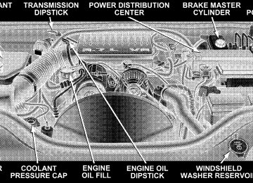
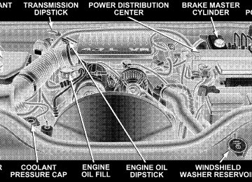
If the rear wiper is operating when the ignition is turned OFF, the wiper will automatically return to the “Park” position. If the liftgate flipper glass is open, connection to the rear window wiper is interrupted preventing activation of the rear wiper blade. When the liftgate flipper glass is closed, the rear wiper switch or the ignition switch needs to be turned OFF and ON to restart the rear wiper. Adding Washer Fluid The fluid reservoir for the windshield washers and the rear window washer is shared. It is located in the front of the engine compartment on the passenger side and should be checked for fluid level at regular intervals. Fill the reservoir with windshield washer solvent (not radia- tor antifreeze) and operate the system for a few seconds to flush out the residual water.
UNDERSTANDING THE FEATURES OF YOUR VEHICLE 171
ROOF LUGGAGE RACK — IF EQUIPPED External racks do not increase the total load carrying capacity of the vehicle. Be sure that the total occupant and luggage load inside the vehicle, plus the load on the luggage rack, do not exceed the rated vehicle capacity. This vehicle is not equipped with roof rack cross rails as built, unless ordered as optional equipment. Cross rails must be installed prior to carrying loads on the roof rack. If not equipped, your authorized dealer can order and install Mopar威 cross rails built specifically for this roof rack system or a number of after market rails that are tailored to your life-style or activities.
172 UNDERSTANDING THE FEATURES OF YOUR VEHICLE
NOTE: The optional cross rails have seven specific locations identified by a feature on both the side rail and the cross rail. Cross rails must be secured in one of the seven detent locations on the side rail to prevent move- ment with a sudden stop. For improved windnoise performance when cross rails are not in use, place them in detent positions #2 (second detent from the front of the vehicle) and #7 (detent closest to the rear of the vehicle) as indicated with a unique feature on the side rails.
CAUTION!
• To prevent damage to the roof of your vehicle, DO NOT
carry any loads on the roof rack without cross rails installed. The load should be secured and placed on top of the cross rails, not directly on the roof. If it is necessary to place the load on the roof, place a blanket or some other protection between the load and the roof surface.
• To avoid damage to the roof rack and vehicle, do not
exceed the rated load capacity of your cross rail system or the roof rack system maximum load capacity of 150
lbs (68 kg). Always distribute heavy loads as evenly as possible and secure the load appropriately.• Long loads which extend over the windshield, such as • Travel at reduced speeds and turn corners carefully
wood panels or surfboards, should be secured to both the front and rear of the vehicle.
when carrying large or heavy loads on the roof rack. Wind forces, due to natural causes or nearby truck traffic, can add sudden upward loads. This is especially true on large flat loads and may result in damage to the cargo or your vehicle.
WARNING!
Cargo must be securely tied before driving your vehicle. Improperly secured loads can fly off the vehicle, particularly at high speeds, resulting in personal injury or property damage. Follow the roof rack “Cautions” when carrying cargo on your roof rack.
UNDERSTANDING THE FEATURES OF YOUR VEHICLE 173
UNDERSTANDING YOUR INSTRUMENT PANEL
CONTENTS
䡵 Instrument Panel And Interior Controls . . . . . . . 178
䡵 Instrument Cluster . . . . . . . . . . . . . . . . . . . . . . 179
䡵 Instrument Cluster Description . . . . . . . . . . . . . 180
䡵 Electronic Vehicle Information Center —If Equipped . . . . . . . . . . . . . . . . . . . . . . . . . . . 187
▫ Customer Programmable Features . . . . . . . . . 190
▫ Compass/Temperature/Trip Computer . . . . . . 195
▫ Trip Computer . . . . . . . . . . . . . . . . . . . . . . . 197
䡵 Radio General Information . . . . . . . . . . . . . . . . 201▫ Radio Broadcast Signals . . . . . . . . . . . . . . . . . 201
▫ Two Types Of Signals . . . . . . . . . . . . . . . . . . 202
▫ Electrical Disturbances . . . . . . . . . . . . . . . . . . 202
▫ AM Reception . . . . . . . . . . . . . . . . . . . . . . . 202
▫ FM Reception . . . . . . . . . . . . . . . . . . . . . . . . 202䡵 Sales Code RAQ – AM/FM/CD (6-Disc) Radio
With Optional Satellite Radio, Hands Free Phone, And Vehicle Entertainment Systems (VES) Capabilities . . . . . . . . . . . . . . . . . . . . . . . . . . . 202
▫ Operating Instructions - Radio Mode . . . . . . . 203176 UNDERSTANDING YOUR INSTRUMENT PANEL
▫ Operation Instructions -
(CD Mode For CD Audio Play)
. . . . . . . . . . . 208
▫ Operating Instructions - Hands Free Phone —
If Equipped . . . . . . . . . . . . . . . . . . . . . . . . . 223
▫ Load/Eject Button
(CD Mode For CD Audio Play)
▫ Notes On Playing MP3 Files ▫ Operation Instructions -
. . . . . . . . . . . 209
. . . . . . . . . . . . . 211(CD Mode For MP3 Audio Play)
. . . . . . . . . . 214
▫ Load/Eject Button (CD Mode For MP3 Play) . . 214䡵 Sales Code REF — AM/FM/CD (Single Disc)
Radio With Optional Satellite Radio And Hands Free Phone Capability . . . . . . . . . . . . . . . . . . . 216
▫ Operating Instructions - Radio Mode . . . . . . . 216
▫ Operation Instructions - CD Mode . . . . . . . . . 220
▫ Operation Instructions - Auxiliary Mode . . . . . 222▫ Operating Instructions - Satellite Radio —
If Equipped . . . . . . . . . . . . . . . . . . . . . . . . . 224
䡵 Sales Code REC — AM/FM/CD (6–Disc)
Radio With Navigation System . . . . . . . . . . . . . 224
▫ Operating Instructions — Satellite Radio(If Equipped)
. . . . . . . . . . . . . . . . . . . . . . . . 224
▫ Clock Setting Procedure . . . . . . . . . . . . . . . . . 225䡵 Video Entertainment System (Sales Code XRV) —
If Equipped . . . . . . . . . . . . . . . . . . . . . . . . . . . 225
䡵 Satellite Radio — If Equipped . . . . . . . . . . . . . . 226
▫ System Activation . . . . . . . . . . . . . . . . . . . . . 227
▫ Electronic Serial Number/Sirius IdentificationNumber (ESN/SID) . . . . . . . . . . . . . . . . . . . . 227
▫ Selecting Satellite Mode In REF Radios . . . . . . 228
▫ Selecting Satellite Mode In RAQ Radios . . . . . 228
▫ Selecting a Channel . . . . . . . . . . . . . . . . . . . . 228
▫ Storing And Selecting Pre-Set Channels . . . . . . 229
▫ Using The PTY (Program Type) Button —If Equipped . . . . . . . . . . . . . . . . . . . . . . . . . 229
▫ PTY Button ⬙Scan⬙ . . . . . . . . . . . . . . . . . . . . . 229
▫ PTY Button ⬙Seek⬙ . . . . . . . . . . . . . . . . . . . . . 229
▫ Satellite Antenna . . . . . . . . . . . . . . . . . . . . . . 230
▫ Reception Quality . . . . . . . . . . . . . . . . . . . . . 230
䡵 Remote Sound System Controls — If Equipped . . 230
▫ Radio Operation . . . . . . . . . . . . . . . . . . . . . . 231
▫ CD Player . . . . . . . . . . . . . . . . . . . . . . . . . . 231UNDERSTANDING YOUR INSTRUMENT PANEL 177
䡵 CD/DVD Disc Maintenance . . . . . . . . . . . . . . . 232
䡵 Radio Operation And Cellular Phones . . . . . . . . 232
䡵 Climate Controls . . . . . . . . . . . . . . . . . . . . . . . 233
▫ Climate Controls — Manual . . . . . . . . . . . . . . 233
▫ Operating Tips . . . . . . . . . . . . . . . . . . . . . . . 237
▫ Automatic Temperature Control —If Equipped . . . . . . . . . . . . . . . . . . . . . . . . . 238
▫ Summer Operation . . . . . . . . . . . . . . . . . . . . 244
▫ Winter Operation . . . . . . . . . . . . . . . . . . . . . 244
▫ Vacation Storage . . . . . . . . . . . . . . . . . . . . . . 245
▫ Window Fogging . . . . . . . . . . . . . . . . . . . . . 245
▫ Outside Air Intake . . . . . . . . . . . . . . . . . . . . 245178 UNDERSTANDING YOUR INSTRUMENT PANEL
INSTRUMENT PANEL AND INTERIOR CONTROLS
INSTRUMENT CLUSTER
UNDERSTANDING YOUR INSTRUMENT PANEL 179
180 UNDERSTANDING YOUR INSTRUMENT PANEL
INSTRUMENT CLUSTER DESCRIPTION
1. Speedometer Indicates vehicle speed. 2. Brake Warning Light
The BRAKE warning light will come on when the ignition is first turned on, and stay on briefly as a bulb check. If the bulb does not come on during starting, have the bulb re- paired promptly. If the light stays on longer, it may be an indication that the parking brake has not been released. If the light remains on when the parking brake is off, it indicates a possible brake hydraulic system malfunction or low fluid level. In this case, the light will remain on until the cause is corrected. If a brake malfunction is indicated, immediate repair is necessary and continued operation of the vehicle in this condition is dangerous.
3. Turn Signal Indicator Light
The arrow will flash with the exterior turn signal when the turn signal lever is operated.
If the vehicle electronics sense that the vehicle has traveled about one mile with the turn signals on, a chime will sound to alert you to turn the signals off. If either indicator flashes at a rapid rate, check for a defective outside light bulb. 4. High Beam Indicator Light
Indicates that headlights are on high beam.
5. Malfunction Indicator Light
This light is part of an onboard diagnostic system called OBD II that monitors engine and auto- matic transmission control systems. The light will illuminate when the key is in the ON position before
engine start. If the bulb does not come on when turning the key from OFF to ON, have the condition checked promptly. Certain conditions such as a loose or missing gas cap, poor fuel quality, etc. may illuminate the light after engine start. The vehicle should be serviced if the light stays on through several of your typical driving cycles. In most situations the vehicle will drive normally and will not require towing. The Malfunction Indicator Light flashes to alert you to serious conditions that could lead to immediate loss of power or severe catalytic converter damage. The vehicle should be serviced as soon as possible if this occurs. (See page 347 for more information.)
UNDERSTANDING YOUR INSTRUMENT PANEL 181
6. Airbag Warning Light
This light turns on and remains on for 6 to 8
seconds as a bulb check when the ignition switch is first turned ON. If the light is not on during starting, stays on, or turns on while driving, have the system inspected by an authorized dealer as soon as possible. 7. Anti-Lock Brake Warning LightThis light monitors the Anti-Lock Brake System. The light will turn on when the ignition switch is turned to the ON position and may stay on for as long as four seconds. If the ABS light remains on or turns on while driving, it indicates that the Anti-Lock portion of the brake system is not functioning and that service is required. However, the conventional brake system will continue to operate normally if the BRAKE warning light is not on.
182 UNDERSTANDING YOUR INSTRUMENT PANEL
If the ABS light is on, the brake system should be serviced as soon as possible to restore the benefits of Anti-Lock brakes. If the ABS light does not turn on when the Ignition switch is turned to the ON position, have the light inspected by an authorized dealer. 8. Tachometer The red segments indicate the maximum permissible engine revolutions-per-minute (r.p.m. x 1000) for each gear range. Before reaching the red area, ease up on the accelerator. 9. Security Alarm System Indicator Light — If Equipped This light will flash rapidly for approximately 15 seconds when the vehicle theft alarm is arming. The light will flash at a slower speed continuously after the alarm is set. The security light will also come on for about three seconds when the ignition is first turned on.
10. Oil Pressure Warning Light
This light shows low engine oil pressure. The light should turn on momentarily when the engine is started. If the light turns on while driving, stop the vehicle, and shut off the engine as soon as possible. A continuous chime will sound when this light turns on. Do not operate the vehicle until the cause is corrected. This light does not show how much oil is in the engine. The engine oil level must be checked under the hood. 11. Electronic Stability Program (ESP) Indicator Light/Traction Control System (TCS) Indicator Light
This indicator light starts to flash as soon as the tires lose traction and the ESP system becomes active. The “ESP/TCS Indicator Light” also flashes when TCS is active. If the “ESP/TCS Indicator Light” begins to flash during acceleration, ease up on the accelerator and apply as little throttle as possible. Be sure to adapt your speed and driving to the
prevailing road conditions. The “ESP/TCS Indicator Light” will flash any time the ESP or TCS is active and helping to improve vehicle stability. If the “ESP/TCS Indicator Light” is on solid, the ESP system has been turned off by the driver or a temporary condition exists that will not allow full ESP function. (See page 131 for more information.) 12. Tire Pressure Monitoring Telltale Light
Each tire, including the spare (if provided), should be checked monthly when cold and inflated to the inflation pressure recommended by the vehicle manufacturer on the vehicle placard or tire inflation pressure label. (If your vehicle has tires of a different size than the size indicated on the vehicle placard or tire inflation pressure label, you should determine the proper tire inflation pressure for those tires.)
UNDERSTANDING YOUR INSTRUMENT PANEL 183
As an added safety feature, your vehicle has been equipped with a tire pressure monitoring system (TPMS) that illuminates a low tire pressure telltale when one or more of your tires is significantly under-inflated. Accord- ingly, when the low tire pressure telltale illuminates, you should stop and check your tires as soon as possible, and inflate them to the proper pressure. Driving on a signifi- cantly under-inflated tire causes the tire to overheat and can lead to tire failure. Under-inflation also reduces fuel efficiency and tire tread life, and may affect the vehicle’s handling and stopping ability. Please note that the TPMS is not a substitute for proper tire maintenance, and it is the driver’s responsibility to maintain correct tire pressure, even if under-inflation has not reached the level to trigger illumination of the TPMS low tire pressure telltale. (See page 294 for more infor- mation.)
184 UNDERSTANDING YOUR INSTRUMENT PANEL
13. Temperature Gauge The temperature gauge shows engine coolant tempera- ture. Any reading within the normal range indicates that the engine cooling system is operating satisfactorily. The gauge pointer will likely indicate a higher tempera- ture when driving in hot weather, up mountain grades, or when towing a trailer. It should not be allowed to exceed the upper limits of the normal operating range.
CAUTION!
Driving with a hot engine cooling system could damage your vehicle. If temperature gauge reads (H), pull over and stop the vehicle. Idle the vehicle with the air conditioner turned off until the pointer drops back into the normal range. If the pointer remains on the “H”, and you hear continuous chimes, turn the engine off immediately, and call for service.
WARNING!
A hot engine cooling system is dangerous. You or others could be badly burned by steam or boiling coolant. If you decide to look under the hood your- self, refer to Section 7 of this manual. Follow the warnings under “Cooling System Pressure Cap.”
14. Electronic Vehicle Information Center Display When the appropriate conditions exist, this display shows the Electronic Vehicle Information Center (EVIC) mes- sages. Refer to “Electronic Vehicle Information Center” later in this section. (See page 187 for more information.) 15. TOW/HAUL Indicator Light
This light will illuminate when the TOW/ HAUL button has been selected. The TOW/ HAUL button is located in the center of the instrument panel (below the climate controls).
16. Electronic Stability Program (ESP) Warning Light/Brake Assist System (BAS) Warning Light — If Equipped
The ESP/BAS warning light in the instrument cluster comes on when the ignition switch is turned to the “ON” position. The light should go out with the engine running. If the ESP/ BAS warning light comes on continuously with the engine running, a malfunction has been detected in either the ESP or the BAS system. If this light stays illuminated, have the ESP and BAS checked at your authorized dealer as soon as possible. (See page 131 for more information.) 17. 4WD LOW Mode Indicator Light — If Equipped
This light alerts the driver that the vehicle is in the 4WD LOW mode. The front and rear drive- shafts are mechanically locked together forcing the front and rear wheels to rotate at the same
speed. (See page 262 for more information.)
UNDERSTANDING YOUR INSTRUMENT PANEL 185
18. Seat Belt Reminder Light
When the ignition switch is first turned ON, this light will turn on for 5 to 8 seconds as a bulb check. During the bulb check, if the driver’s seat belt is unbuckled, a chime will sound. After the bulb check or when driving, if the driver or front passenger seat belt remains unbuckled, the Seat Belt Warning Light will flash or remain on continuously. Refer to ⬙Enhanced Driver Seat Belt Reminder System (BeltAlert)⬙ in the Occupant Restraints section for more information. 19. Cruise Indicator Light
This indicator lights when the speed control system is turned ON.
20. Odometer The odometer shows the total distance the vehicle has been driven.
186 UNDERSTANDING YOUR INSTRUMENT PANEL
U.S. federal regulations require that upon transfer of vehicle ownership, the seller certify to the purchaser the correct mileage that the vehicle has been driven. There- fore, if the odometer reading is changed during repair or replacement, be sure to keep a record of the reading before and after the service so that the correct mileage can be determined. 21. Transmission Range Indicator This display indicator shows the automatic transmission gear selection. 22. Fuel Gauge The pointer shows the level of fuel in the fuel tank when the ignition switch is in the ON position. 23. Electronic Throttle Control (ETC) Warning Light — If Equipped
This light informs you of a problem with the Electronic Throttle Control system. If a problem is detected the light will come on while the
engine is running. Cycle the ignition key when the vehicle has completely stopped and the gear selector is placed in the P (Park) position. The light should turn off. If the light remains lit with the engine running your vehicle will usually be drivable, however, see your dealer for service as soon as possible. If the light is flashing when the engine is running, immediate service is re- quired and you may experience reduced performance, an elevated/rough idle or engine stall and your vehicle may require towing. The light will come on when the ignition is first turned on and remain on briefly as a bulb check. If the light does not come on during starting, have the system checked by an authorized dealer. 24. Front Fog Light Indicator Light— If Equipped This light shows the front fog lights are ON.
25. Voltage Warning Light
This light monitors the electrical system voltage. The light should turn on momentarily as the engine is started. If the light stays on or turns on while driving, it indicates a problem with the charging system. Immediate service should be obtained. 26. Low Fuel Warning Light
When the fuel level reaches approximately 2.3 U.S. Gallons (8.7 Liters) this light will come on and remain on until fuel is added. The Low Fuel Warning Light may turn on and off again, especially during and after hard braking, accelerations, or turns. This occurs due to the shifting of the fuel in the tank. Also, a single chime will sound.
UNDERSTANDING YOUR INSTRUMENT PANEL 187
ELECTRONIC VEHICLE INFORMATION CENTER — IF EQUIPPED
The electronic vehicle information center (EVIC) located in the instrument cluster, when the appropriate condi- tions exist, will display the following messages and symbols. Some of the messages are accompanied by a chime.
188 UNDERSTANDING YOUR INSTRUMENT PANEL
GRAM LIMIT
• TURN SIGNAL ON • PERFORM SERVICE • KEY NOT PROGRAMMED — DAMAGED KEY • KEY NOT PROGRAMMED — INVALID KEY • KEY NOT PROGRAMMED — EXCEEDED KEY PRO- • PROGRAMMING ACTIVE — NEW KEY PRO- • SERVICE SECURITY KEY • INVALID KEY — TRY ALTERNATE KEY • DRIVER/PASSENGER DOOR OPEN (with graphic) • LEFT/RIGHT REAR DOOR OPEN (with graphic) • X DOORS OPEN (with graphic) • LIFTGATE OPEN (with graphic)
GRAMMED
• LIFTGATE/DOOR OPEN (with graphic) • LIFTGATE/DOORS OPEN (with graphic) • LIFTGLASS OPEN (with graphic) • HOOD OPEN (with graphic) • HOOD/DOOR OPEN (with graphic) • HOOD/DOORS OPEN (with graphic) • LIFTGATE/HOOD OPEN (with graphic) • HOOD/GLASS/DOOR OPEN (with graphic) • HOOD/GLASS/DOORS OPEN (with graphic) • HOOD/GATE/DOOR OPEN (with graphic) • HOOD/GATE/DOORS OPEN (with graphic) • LIFTGLASS/DOOR OPEN (with graphic) • LIFTGLASS/DOORS OPEN (with graphic)
• LIFTGLASS/HOOD OPEN (with graphic) • WASHER FLUID LOW (with graphic) • CHECK GAUGES • AUTO HIGHBEAM ON • AUTO HIGHBEAM OFF • PARK ASSIST DISABLED • SERVICE PARK ASSIST SYSTEM • TRANSMISSION OVER TEMP • CHECK SHIFT PROCEDURE • SERVICE 4WD SYSTEM • 4WD SYSTEM IN NEUTRAL • LOW BRAKE FLUID LEVEL • WARNING! LIMIT SPEED
UNDERSTANDING YOUR INSTRUMENT PANEL 189
TENED (with graphic)
• CHECK GAS CAP • ESP OFF • MEMORY #1 POSITIONS SET • MEMORY #2 POSITIONS SET • MEMORY SYSTEM DISABLED — SEATBELT FAS- • MEMORY SYSTEM DISABLED — VEHICLE NOT IN • DRIVER 1 MEMORY • DRIVER 2 MEMORY • PEDAL ADJUST DISABLED — CRUISE CONTROL • PEDAL ADJUST DISABLED — SHIFTER IN RE-
PARK
SET
VERSE
190 UNDERSTANDING YOUR INSTRUMENT PANEL
tem Only)
tem Only)
• SERVICE TIRE PRESS SYSTEM • LEFT FRONT LOW PRESSURE (Premium TPM Sys- • RIGHT FRONT LOW PRESSURE (Premium TPM Sys- • LEFT REAR LOW PRESSURE (Premium TPM System • RIGHT REAR LOW PRESSURE (Premium TPM Sys- • SPARE LOW PRESSURE (Premium TPM System
tem Only)
Only)
Only)
Customer Programmable Features Press the MENU button until one of the display choices following appears:
Menu Button
Language? When in this display you may select one of three lan- guages for all display nomenclature, including the trip computer functions. Press the STEP button while in this display selects English, Espanol, or Francais. As you continue the displayed information will be shown in the selected language.
Step Button
UNDERSTANDING YOUR INSTRUMENT PANEL 191
Display U.S. or Metric? Pressing the STEP button when in this display selects US or Metric. The overhead console and instrument panel displays will be in the selected units. Auto Door Locks? When this feature is selected, all doors and the liftgate lock automatically when the speed of the vehicle reaches 15 mph (25 km/h). Pressing the STEP button when in this display will select “Yes” or “No.” Auto Unlock On Exit? (Available Only When the AUTO DOOR LOCKS Feature is Turned On ) When this feature is selected all the vehicle’s doors will unlock when the driver’s door is opened if the vehicle is stopped and the transmission is in P (Park) or N (Neu- tral) position. Pressing the STEP button when in this display will select “Yes” or “No.”
192 UNDERSTANDING YOUR INSTRUMENT PANEL
Remote Unlock Driver’s Door 1st? When this feature is selected only the driver’s door will unlock on the first press of the remote keyless entry unlock button and require a second press to unlock the remaining locked doors and liftgate. When REMOTE UNLOCK ALL DOORS is selected all of the doors and the liftgate will unlock at the first press of the remote keyless entry unlock button. Pressing the STEP button when in this display will select DRIVER’S DOOR 1ST or ALL DOORS. Remote Linked To Memory? (Available with Memory Seat Only) When this feature is selected the memory seat, mirror, and radio settings will return to the memory set position when the remote keyless entry “Unlock” button is pressed. If this feature is not selected then the memory seat, mirror, and radio settings can only return to the
memory set position using the door mounted switch. Pressing the STEP button when in this display will select “Yes” or “No.” Sound Horn With Lock? When this feature is selected a short horn sound will occur when the remote keyless entry “Lock” button is pressed. This feature may be selected with or without the flash lights on lock/unlock feature. Pressing the STEP button when in this display will select “Yes” or “No.” Flash Lights With Lock? When this feature is selected, the front and rear turn signals will flash when the doors are locked or unlocked using the remote keyless entry transmitter. This feature may be selected with or without the sound horn on lock feature selected. Pressing the STEP button when in this display will select “Yes” or “No.”
Headlamp Delay When this feature is selected the driver can choose, when exiting the vehicle, to have the headlamps remain on for 30, 60, or 90 seconds, or not remain on. Pressing the STEP button when in this display will select 30, 60, 90, or OFF. Illuminated Approach? When this feature is selected the driver can choose, when entering the vehicle, to have the headlamps come on for 30, 60, or 90 seconds, or not come on at all. Pressing the STEP button when in this display will select 30, 60, 90, or OFF. Auto Headlamp Low/High Beams? (Available with SmartBeam Only) When this feature is selected and the headlight switch has been moved to the A (Auto) position, the headlights will automatically switch from high to low beams when approaching a vehicle. Pressing the STEP button when in
UNDERSTANDING YOUR INSTRUMENT PANEL 193
this display will select “Low Beam” or “Low/High Beam.” Refer to “Lights — SmartBeams” in Section 3 of this manual. NOTE: System will activate at or above 20 mph (32
km/h). Headlamps On With Wipers? (Available with Auto Headlights Only) When this feature is selected and the headlight switch has at least once been moved to the A (Auto) position, the headlights will turn on when the wipers are turned on. The headlights will also turn off when the wipers are turned off if they were turned on in this way. Pressing the STEP button when in this display will select “Yes” or “No.” NOTE: Turning the headlights on during the daytime causes the instrument panel lights to dim. To increase the brightness, refer to “Lights” in Section 3 of this manual.194 UNDERSTANDING YOUR INSTRUMENT PANEL
Front Wipers Rain Sense? (Available with Rain Sensing Wipers Only) Pressing the STEP button when in this display will select “Manual” or “Rain Sense.” Service Interval When this feature is selected a service interval between 2,000 (3 200 km) and 6,000 miles (10 000 km) in 500 mile (800 km) increments may be selected. Pressing the STEP button when in this display will select distances between 2,000 (3 200 km) and 6,000 miles (10 000 km) in 500 mile (800 km) increments. Reset Service Distance (Displays Only if Service Interval was Changed) When this feature is selected the current accumulated service distance can be reset to the newly selected service interval. Pressing the STEP button when in this display will select “Yes” or “No.”
Easy Entry/Exit Seat? (Available with Memory Seat Only) This feature provides automatic driver’s seat positioning which will enhance driver mobility out of and into the vehicle. The Easy Entry/ Easy Exit feature is not enabled when the vehicle is delivered from the factory. The Easy Entry/ Easy Exit feature is enabled (or later disabled) through the programmable features in the Electronic Vehicle Information Center (EVIC). Pressing the STEP button when in this display will select “Yes” or “No.” The seat will return to the memorized seat location (if REMOTE LINK TO MEMORY is set to YES) when the remote keyless entry transmitter is used to unlock the door. For more information, refer to “Easy Entry/Exit Seat — Driver Memory Seat” in Section 3 of this manual. (See page 117 for more information.)
Compass/Temperature/Trip Computer This display provides the outside temperature, one of the eight compass headings to indicate the direction the vehicle is facing, and vehicle trip information. The com- pass and temperature display is the normal display. When the C/T button is pressed the compass/ temperature display returns.
UNDERSTANDING YOUR INSTRUMENT PANEL 195
Compass/Temperature Button
196 UNDERSTANDING YOUR INSTRUMENT PANEL
WARNING!
Even if the display still reads a few degrees above 32°F ( 0°C), the road surface may be icy, particularly in woods or on bridges. Drive carefully under such conditions to prevent an accident and possible per- sonal injury or property damage.
Compass/Temperature Display
Trip Computer This feature, located in the instrument cluster, displays the following information when the display is in the “Compass/Temperature” mode and the STEP button is pressed: Step Button Press the STEP button to cycle through all of Compass/Mini-Trip Computer displays.
the
UNDERSTANDING YOUR INSTRUMENT PANEL 197
Step Button
198 UNDERSTANDING YOUR INSTRUMENT PANEL
Reset Button Press the RESET button to reset the display you are in. Press and hold the RESET button (for 2 seconds) to reset all of the displays.
Reset Button
Average Fuel Economy Shows the average fuel economy since the last reset. When the fuel economy is reset, the display will read “RESET” or show dashes for two seconds. Then, the history information will be erased, and the averaging will continue from the last fuel average reading before the reset. Distance To Empty Shows the estimated distance that can be travelled with the fuel remaining in the tank. This is calibrated using the miles per gallon during the last driving period. Trip A Shows the total distance travelled for trip A since the last reset. Trip B Shows the total distance travelled for trip B since the last reset.
Elapsed Time Shows the accumulated ignition ON time since the last reset. Tire Pressure Display — If Equipped Shows the current pressure of all 4 road tires.
Tire Pressure Display
UNDERSTANDING YOUR INSTRUMENT PANEL 199
NOTE: Tires heat up during normal driving conditions. Heat will cause the tire pressure to increase from 2 to 6
psi (14 to 41 kPa) during normal driving conditions. Refer to “Tire Inflation Pressures” in Section 5 for additional information. Miles to Service Shows the distance remaining to require service. NOTE: This display can be reset to the set service interval by pressing and holding the RESET button for 3
seconds. Blank Screen Shows a blank screen. Pressing the C/T button returns to the compass/temperature display. Manual Compass Calibration If the compass appears erratic and the “CAL” symbol does not appear, you must manually put the compass into the “Calibration” mode.200 UNDERSTANDING YOUR INSTRUMENT PANEL
NOTE: To ensure proper compass calibration, make sure the compass variance is properly set before manu- ally calibrating the compass. Refer to Variance Map. To Put Into a Calibration Mode Start the engine and leave the transmission in the P (Park) position. Set the display to “Compass/Temperature.” Press and hold the C/T button for approximately 5
seconds to change the display to compass variance mode; holding the button for an additional 5 seconds will flash the “CAL” symbol indicating compass calibration mode. When the “CAL” indicator is flashing, complete one or more 360 degree turns, under 5 mph (8 km/h), in an area free from large metal objects or power lines. The “CAL” indicator will turn off and the compass will function normally.Compass/Temperature Button
Compass Variance is the difference between magnetic north and geographic north. In some areas of the country, the difference between magnetic and geographic north is great enough to cause the compass to give false readings. If this occurs, the compass variance must be set according to the Compass Variance Map.
UNDERSTANDING YOUR INSTRUMENT PANEL 201
To set the variance: Turn the ignition ON and set the display to “Compass/Temperature.” Press the C/T but- ton for approximately 5 seconds. The last variance zone number will be displayed. Press and hold the STEP button for 1 second to select the new variance zone and press the RESET button to resume normal operation.
RADIO GENERAL INFORMATION
Radio Broadcast Signals Your new radio will provide excellent reception under most operating conditions. Like any system, however, car radios have performance limitations, due to mobile op- eration and natural phenomena, which might lead you to believe your sound system is malfunctioning. To help you understand and save you concern about these “ap- parent” malfunctions, you must understand a point or two about the transmission and reception of radio sig- nals.
202 UNDERSTANDING YOUR INSTRUMENT PANEL
Two Types of Signals There are two basic types of radio signals... AM or Amplitude Modulation, in which the transmitted sound causes the amplitude, or height, of the radio waves to vary... and FM or Frequency Modulation, in which the frequency of the wave is varied to carry the sound. Electrical Disturbances Radio waves may pick up electrical disturbances during transmission. They mainly affect the wave amplitude, and thus remain a part of the AM reception. They interfere very little with the frequency variations that carry the FM signal. AM Reception AM sound is based on wave amplitude, so AM reception can be disrupted by such things as lightning, power lines and neon signs.
FM Reception Because FM transmission is based on frequency varia- tions, interference that consists of amplitude variations can be filtered out, leaving the reception relatively clear, which is the major feature of FM radio. NOTE: On vehicles so equipped the radio, steering wheel radio controls and 6 disc CD/DVD changer will remain active for up to 45 seconds after the ignition switch has been turned off. Opening a vehicle front door will cancel this feature.
SALES CODE RAQ – AM/FM/CD (6-DISC) RADIO WITH OPTIONAL SATELLITE RADIO, HANDS FREE PHONE, AND VEHICLE ENTERTAINMENT SYSTEMS (VES) CAPABILITIES
NOTE: The radio sales code is located on the lower right side of your radio faceplate.
UNDERSTANDING YOUR INSTRUMENT PANEL 203
Power Switch/Volume Control (Rotary) Press the ON/VOL control to turn the radio ON. Press the ON/VOL a second time to turn OFF the radio. Electronic Volume Control The electronic volume control turns continuously (360
degrees) in either direction without stopping. Turning the volume control to the right increases the volume and to the left decreases it. When the audio system is turned on, the sound will be set at the same volume level as last played. For your convenience, the volume can be turned down, but not up, when the audio system is off and the ignition is ON. Mode Button (Radio Mode) Press the mode button repeatedly to select between the CD player, Satellite Radio, or Vehicle Entertainment System (VES) (if equipped).Operating Instructions - Radio Mode
RAQ Radio
NOTE: The ignition switch must be in the ON or ACC position to operate the radio.
204 UNDERSTANDING YOUR INSTRUMENT PANEL
SEEK Button (Radio Mode) Press and release the SEEK button to search for the next listenable station in either AM/FM or Satellite (if equipped) mode. Press the right side of the button to seek up and the left side to seek down. The radio will remain tuned to the new station until you make another selec- tion. Holding the button will bypass stations without stopping until you release it. MUTE Button (Radio Mode) Press the MUTE button to cancel the sound from the speakers. ⬙MUTE⬙ will be displayed. Press the MUTE button a second time and the sound from the speakers will return. Rotating the volume control, turning the radio ON/OFF, or turning OFF the ignition will also return the sound from the speakers NOTE: MUTE button mutes the microphone.
In Hands Free Phone (if equipped) mode, the
SCAN Button (Radio Mode) Pressing the SCAN button causes the tuner to search for the next listenable station, in either AM, FM or Satellite (if equipped) frequencies, pausing for 5 seconds at each listenable station before continuing to the next. To stop the search, press SCAN a second time. MSG or INFO Button (Radio Mode) Press the MSG or INFO button for an RBDS station (one with call letters displayed). The radio will return a Radio Text message broadcast from an FM station (FM mode only). Time Button Press the time button and the time of day will be displayed for 5 seconds. Clock Setting Procedure 1. Press and hold the time button until the hours blink.
2. Adjust the hours by turning the right side Tune / Audio control. 3. After the hours are adjusted, press the right side Tune / Audio control to set the minutes. The minutes will begin to blink. 4. Adjust the minutes using the right side Tune / Audio control. 5. To exit, press any button/knob or wait 5 seconds. RW/FF (Radio Mode) Pressing the rewind/fast forward button causes the tuner to search for the next frequency in the direction of the arrows. This feature operates in either AM, FM or Satel- lite (if equipped) frequencies. TUNE Control (Radio Mode) Turn the right side rotary control clockwise to increase or counter-clockwise to decrease the frequency.
UNDERSTANDING YOUR INSTRUMENT PANEL 205
AM/FM Button (Radio Mode) Press the button to select AM or FM Modes. Setting the Tone, Balance, and Fade Press the rotary TUNE control and BASS will display. Turn the TUNE control to the right or left to increase or decrease the Bass tones. Press the rotary TUNE control a second time and MID will display. Turn the TUNE control to the right or left to increase or decrease the Mid Range tones. Press the rotary TUNE control a third time and TREBLE will display. Turn the TUNE control to the right or left to increase or decrease the Treble tones. Press the rotary TUNE control a fourth time and BAL- ANCE will display. Turn the TUNE control to the right or left to adjust the sound level from the right or left side speakers.
206 UNDERSTANDING YOUR INSTRUMENT PANEL
Press the rotary TUNE control a fifth time and FADE will display. Turn the TUNE control to the left or right to adjust the sound level between the front and rear speak- ers. Press the rotary TUNE control again to exit setting tone, balance and fade. RND/PTY Button (Radio Mode) Pressing this button once will turn on the PTY mode for 5 seconds. If no action is taken during the 5 second time out the PTY icon will turn off. Pressing the PTY button or turning the TUNE rotary knob within 5 seconds will allow the program format type to be selected. Many radio stations do not currently broadcast PTY information.
Toggle the PTY button to select the following format types:
Program Type
No program type or un-
defined
Adult Hits Alert Alert Classical
Classic Rock
College Country
Emergency Test Foreign Language
Information
Jazz News
16 Digit-Character Dis-
play
None
Adult_Hits Alert Alert Classical
Classic_Rock
College Country
Emergency Test Foreign_Language
Information
Jazz News
Nostalgia
Oldies
Personality
Public
Nostalgia
Oldies
Personality
Public
Rhythm and Blues Religious Music Religious Talk
Rhythm_and_Blues
Religious_Music Religious_Talk
Rock Soft
Soft Rock
Soft Rhythm and Blues
Sports Talk Top 40
WeatherRock Soft
Soft_Rock Soft_R_&_B
Sports Talk
Top_40
WeatherBy pressing the SEEK button when the PTY icon is displayed, the radio will be tuned to the next frequency
UNDERSTANDING YOUR INSTRUMENT PANEL 207
station with the same selected PTY name. The PTY function only operates when in the FM mode. If a preset button is activated while in the PTY (Program Type) mode, the PTY mode will be exited and the radio will tune to the preset station. SET/DIR Button (Radio Mode) — To Set the Push-Button Memory When you are receiving a station that you wish to commit to push-button memory, press the SET/DIR button. The symbol SET 1 will now show in the display window. Select the button (1-6) you wish to lock onto this station and press and release that button. If a button is not selected within 5 seconds after pressing the SET/DIR button, the station will continue to play but will not be stored into push-button memory. You may add a second station to each push-button by repeating the above procedure with this exception: Press the SET/DIR button twice and SET 2 will show in the
208 UNDERSTANDING YOUR INSTRUMENT PANEL
display window. Each button can be set for SET 1 and SET 2 in both AM and FM. This allows a total of 12 AM,12
FM and 12 Satellite (if equipped) stations to be stored into push-button memory. The stations stored in SET 2
memory can be selected by pressing the push-button twice. Every time a preset button is used a corresponding button number will be displayed. Buttons 1 - 6 (Radio Mode) These buttons tune the Radio to the stations that you commit to push-button memory {12AM, 12 FM, and 12
Satellite (if equipped) stations}. Operation Instructions - (CD MODE for CD Audio Play)NOTE: The ignition switch must be in the ON or ACC position to operate the radio.
NOTE: Note: This Radio is capable of playing compact discs (CD), recordable compact discs (CD-R), rewritable compact discs (CD-RW) compact discs with MP3 tracks and multisession compact discs with CD and MP3 tracks. Inserting Compact Disc(s) Gently insert one CD into the CD player with the CD label facing up. The CD will automatically be pulled into the CD Player and the CD icon will illuminate on the radio display.
CAUTION!
This CD player will accept 4 3/4 inch (12 cm) discs only. The use of other sized discs may damage the CD player mechanism.
You may eject a disc with the radio OFF.
If you insert a disc with the ignition ON and the radio ON, the unit will switch from radio to CD mode and begin to play when you insert the disc. The display will show the disc number, the track number, and index time in minutes and seconds. Play will begin at the start of track 1. SEEK Button (CD MODE for CD Audio Play) Press the right side of the SEEK button for the next selection on the CD. Press the left side of the button to return to the beginning of the current selection, or return to the beginning of the previous selection if the CD is within the first 10 seconds of the current selection. MUTE Button (CD MODE for CD Audio Play) Press the MUTE button to cancel the sound from the speakers. ⬙MUTE⬙ will be displayed. Press the MUTE button a second time and the sound from the speakers
UNDERSTANDING YOUR INSTRUMENT PANEL 209
will return. Rotating the volume control, turning the radio ON/OFF, or turning OFF the ignition will also return the sound from the speakers. SCAN Button (CD MODE for CD Audio Play) Press the Scan button to scan through each track on the CD currently playing. LOAD/EJECT Button (CD Mode for CD Audio Play)
LOAD/ EJECT - Load
Press the LOAD/ EJECT button and the push- button with the corresponding number where the CD is being loaded. The radio will display PLEASE WAIT and prompt when to INSERT DISC. After the radio displays ⬙LOAD DISC⬙ insert the CD into the player.
210 UNDERSTANDING YOUR INSTRUMENT PANEL
Radio display will show ⬙LOADING DISC⬙ when the disc is loading, and “READING DISC” when the radio is reading the disc. LOAD / EJT - Eject
Press the LOAD/ EJT button and the push- button with the corresponding number where the CD was loaded and the disc will unload and move to the entrance for easy removal. Radio display will show ⬙EJECTING DISC⬙ when the disc is being ejected and prompt the user to remove the disc. Press and hold the LOAD/ EJT button for 5 seconds and all CDs will be ejected from the radio. If you have ejected a disc and have not removed it within 15 seconds, it will be reloaded. If the CD is not removed, the radio will continue to play the non-removed CD. If the CD is removed and there are other CD’s in the radio, the radio will play the next CD after a 2 minute timeout. If the CD is removed and there are no other CD’s in the
radio, the radio will remain in CD mode and display ⬙INSERT DISC” for 10 seconds. If no discs are inserted within 10 seconds “NO DISCS LOADED” will be dis- played. On some vehicles a disc can be ejected with the radio and ignition OFF. TIME Button (CD MODE for CD Audio Play) Press this button to change the display from a large CD playing time display to a small CD playing time display. RW/FF (CD MODE for CD Audio Play) Press and hold FF (Fast Forward) and the CD player will begin to fast forward until FF is released or RW or another CD button is pressed. The RW (Reverse) button works in a similar manner. TUNE Control (CD MODE for CD Audio Play) Pressing the TUNE control allows the setting of the Tone,