- 2008 Jeep Compass Owners Manuals
- Jeep Compass Owners Manuals
- 2011 Jeep Compass Owners Manuals
- Jeep Compass Owners Manuals
- 2007 Jeep Compass Owners Manuals
- Jeep Compass Owners Manuals
- 2013 Jeep Compass Owners Manuals
- Jeep Compass Owners Manuals
- 2009 Jeep Compass Owners Manuals
- Jeep Compass Owners Manuals
- 2012 Jeep Compass Owners Manuals
- Jeep Compass Owners Manuals
- 2010 Jeep Compass Owners Manuals
- Jeep Compass Owners Manuals
- Download PDF Manual
-
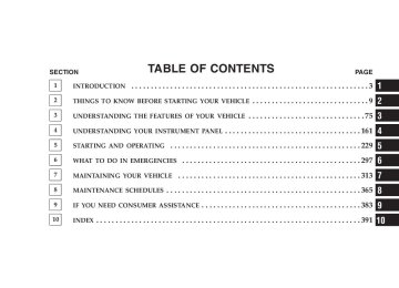
an authorized dealer. If the light comes on and remains on while driving, stop the vehicle and shut off the engine. DO NOT OPERATE THE VEHICLE UNTIL THE CAUSE IS CORRECTED. The light does not show the quantity of oil in the engine. This can be determined using the procedure shown in Section 7. 5. Low Fuel Light
When the fuel level drops to 2 gallons, the fuel symbol will light and a single chime will sound.
UNDERSTANDING YOUR INSTRUMENT PANEL 167
6. Speedometer Indicates vehicle speed. 7. Airbag Light
The light comes on and remains on for 6 to 8
seconds as a bulb check when the ignition switch is first turned ON. If the light does not come on during starting, stays on, or comes on while driving, have the system checked by an authorized dealer. 8. Turn Signal IndicatorsThe arrows will flash in unison with the exterior turn signal, when using the turn signal lever.
9. High Beam Indicator
This light shows that the headlights are on high beam. Push the turn signal lever away from the steering wheel to switch the headlights from high or low beam.
168 UNDERSTANDING YOUR INSTRUMENT PANEL
10. Anti-Lock Warning Light (ABS) — If Equipped
This light monitors the Anti-Lock Brake System (ABS) described elsewhere in this manual. This light will come on when the ignition key is turned to the ON position and may stay on for as long as four seconds.
If the ABS light remains on or comes on during driving, it indicates that the Anti-Lock portion of the brake system is not functioning and that service is required, however, the conventional brake system will continue to operate normally provided that the BRAKE warning light is not on. If the ABS light is on, the brake system should be serviced as soon as possible to restore the benefit of Anti-Lock Brakes. The warning light should be checked frequently to assure that it is operating properly. Turn the ignition key to the
on position, but do not start the vehicle. The light should come on. If the light does not come on, have the system checked by an authorized dealer. 11. Seat Belt Reminder Light
When the ignition switch is first turned ON, this light will come on for about six seconds. A chime will sound if you have not pulled the shoulder belt out of the retractor. This is a reminder to “buckle up”. If you do not buckle up, the light will remain on. 12. Tachometer The white area of the scale shows the permissible engine revolutions-per-minute (rpm x 1000) for each gear range. Before reaching the red area, ease up on the accelerator to prevent engine damage. 13. Engine Temperature Warning Light
This light warns of an overheated engine condi- tion. If the engine is critically hot, a warning chime
will sound 10 times. After the chime turns off, the engine will still be critically hot until the light goes out. 14. Brake System Warning Light
This light monitors various brake functions, in- cluding brake fluid level and parking brake appli- cation. If the brake light turns on, it may indicate that the parking brake is applied, there is a low brake fluid level or there is a problem with the anti-lock brake system. The dual brake system provides a reserve braking capac- ity in the event of a failure to a portion of the hydraulic system. Failure of either half of the dual brake system is indicated by the Brake Warning Light which will turn on when the brake fluid level in the master cylinder has dropped below a specified level. The light will remain on until the cause is corrected.
UNDERSTANDING YOUR INSTRUMENT PANEL 169
NOTE: The light may flash momentarily during sharp cornering maneuvers which change fluid level condi- tions. The vehicle should have service performed, and the brake fluid level checked. If brake failure is indicated, immediate repair is neces- sary.
WARNING!
Driving a vehicle with the brake light on is danger- ous. Part of the brake system may have failed. It will take longer to stop the vehicle. You could have an accident. Have the vehicle checked immediately.
Vehicles equipped with Anti-Lock brakes (ABS), are also equipped with Electronic Brake Force Distribution (EBD).
170 UNDERSTANDING YOUR INSTRUMENT PANEL
In the event of an EBD failure, the Brake Warning Light will turn on along with the ABS Light. Immediate repair to the ABS system is required. The operation of the Brake Warning Light can be checked by turning the ignition switch from the OFF position to the ON position. The light should illuminate for approxi- mately two seconds. The light should then turn off unless the parking brake is applied or a brake fault is detected. If the light does not illuminate, have the light inspected by an authorized dealer. The light also will turn on when the parking brake is applied with the ignition switch in the ON position. NOTE: This light shows only that the parking brake is applied. It does not show the degree of brake application.
15. Transmission Over Temp Light
During sustained high speed driving on hot days, the automatic transaxle oil may become too hot. If this happens, the transmission over- indicator light will come on and the heat vehicle will slow slightly until the automatic transaxle cools down enough to allow a return to the requested speed. If the high speed is maintained, the overheating will reoccur as before in a cyclic fashion. 16. Theft Alarm Light — If Equipped This light will flash rapidly for several seconds when the alarm system is arming. The light will begin to flash slowly indicating that the system is armed. 17. Temperature Gauge If the pointer rises to the H (red) mark, the instrument cluster will sound a chime. Pull over and stop the vehicle. Idle the vehicle with the air conditioner turned off until
the pointer drops back into the normal range. If the pointer remains on the H (red) mark, turn the engine off immediately and call for service. There are steps that you can take to slow down an impending overheat condition. If your air conditioning is on, turn it off. The air conditioning system adds heat to the engine cooling system and turning off the A/C removes this heat. You can also turn the Temperature control to maximum heat, the Mode control to Floor and the Fan control to High. This allows the heater core to act as a supplement to the radiator and aids in removing heat from the engine cooling system. 18. Cruise Indicator — If Equipped
This indicator shows that the Speed Control System is ON.
19. Speed Control SET light. This indicator shows that the Speed Control System is SET.
UNDERSTANDING YOUR INSTRUMENT PANEL 171
20. Transmission Range Indicator This display indicator shows the automatic transmission gear selection. 21. Odometer/Trip Odometer Reset Button Press this button to change the display from odometer to either of the two trip odometer settings. Trip A or Trip B will appear when in the trip odometer mode. Push in and hold the button for two seconds to reset the trip odometer to 0 miles or kilometers. The odometer must be in trip mode to reset. 22. Tire Pressure Monitor Light — If Equipped
Each tire, including the spare (if provided), should be checked monthly when cold and inflated to the inflation pressure recommended by the vehicle manufacturer on the vehicle placard or tire inflation pressure label. (If your vehicle has tires of a different size than the size indicated on the
172 UNDERSTANDING YOUR INSTRUMENT PANEL
vehicle placard or tire inflation pressure label, you should determine the proper tire inflation pressure for those tires.) As an added safety feature, your vehicle has been equipped with a tire pressure monitoring system (TPMS) that illuminates a low tire pressure telltale when one or more of your tires are significantly under-inflated. Ac- cordingly, when the low tire pressure telltale illuminates, you should stop and check your tires as soon as possible, and inflate them to the proper pressure. Driving on a significantly under-inflated tire causes the tire to over- heat and can lead to tire failure. Under-inflation also reduces fuel efficiency and tire tread life, and may affect the vehicle’s handling and stopping ability.
Please note that the TPMS is not a substitute for proper tire maintenance, and it is the driver’s responsibility to maintain correct tire pressure, even if under-inflation has not reached the level to trigger illumination of the TPMS low tire pressure telltale. The Tire Pressure Monitoring Telltale Lamp will illumi- nate in the instrument cluster, and an audible chime will be activated when one or more tire pressures is low. The Tire Pressure Monitoring Telltale Lamp will flash on and off for 60 seconds when a system fault is detected. The flash cycle will repeat every ten minutes or until the fault condition is removed and reset. If this indicator comes on, the entire, PRNDL/ odometer, display will brighten to FULL DAYTIME INTENSITY and will not be dimmable.
CAUTION!
The TPMS has been optimized for the original equipment tires and wheels. TPMS pressures and warning have been established for the tire size equipped on your vehicle. Undesirable system op- eration or sensor damage may result when using replacement equipment that is not of the same size, type, and/or style. Aftermarket wheels can cause sensor damage. Do not use tire sealant from a can, or balance beads if your vehicle is equipped with a TPMS, as damage to the sensors may result.
23. Four-Wheel-Drive This light indicates the vehicle is in 4WD. 24. Odometer/Trip Odometer A vacuum fluorescent display indicates the total distance the vehicle has been driven. Also, the cluster will display,
UNDERSTANDING YOUR INSTRUMENT PANEL 173
replacing the odometer/trip odometer, vehicle warning messages such as: door/gate ajar and loose gas cap. Loose gas cap will be displayed from the Odometer/Trip Odometer on all models. If vehicle is equipped with the optional Elec- NOTE: tronic Vehicle Information Center (EVIC) in the instru- ment cluster, all warnings including “door”, and “gATE” will only be displayed in the EVIC display. For additional information, refer to “Electronic Vehicle Information Cen- ter — If Equipped” in Section 3. U.S. federal regulations require that upon transfer of vehicle ownership, the seller certify to the purchaser the correct mileage that the vehicle has been driven. There- fore, if the odometer reading is changed during repair or replacement, be sure to keep a record of the reading before and after the service so that the correct mileage can be determined.
174 UNDERSTANDING YOUR INSTRUMENT PANEL
25. Malfunction Indicator Light
This light is part of an onboard diagnostic system called OBD that monitors emissions, engine, and automatic transmission control systems. The light will illuminate when the key is in the ON/RUN position before engine start. If the bulb does not come on when turning the key from OFF to ON/RUN, have the condi- tion checked promptly. Certain conditions such as a loose or missing gas cap, poor fuel quality, etc. may illuminate the light after engine start. The vehicle should be serviced if the light stays on through several of your typical driving cycles. In most situations the vehicle will drive normally and will not require towing. If the Malfunction Indicator Light flashes when the engine is running, serious conditions may exist that
could lead to immediate loss of power or severe catalytic converter damage. The vehicle should be serviced as soon as possible if this occurs. If this indicator comes on, the entire, PRNDL/ odometer, display will brighten to FULL DAYTIME INTENSITY and will not be dimmable. 26. Front Fog Light Indicator — If Equipped
This light shows when the front fog lights are ON.
27. Electronic Stability Program (ESP) Indicator Light/Traction Control System (TCS) Indicator Light — If Equipped
If this indicator light flashes during accelera- tion, apply as little throttle as possible. While driving, ease up on the accelerator. Adapt your speed and driving to the prevailing road con- ditions, and do not switch off the ESP, or TCS — if equipped.
28. Electronic Stability Program (ESP) Indicator Light The malfunction lamp for the ESP is combined with BAS. The yellow “ESP/BAS Warning Lamp” comes on when the ignition switch is turned to the “ON” position. They should go out with the engine running. If the “ESP/BAS Warning Lamp” comes on continuously with the engine running, a malfunction has been detected in either the ESP or the BAS system. If this light remains on after several ignition cycles, and the vehicle has been driven several miles at speeds greater than 30 mph (48 km/h), see your autho- rized dealer as soon as possible. 29. 4WD Malfunction Light
This light monitors the Four -Wheel-Drive (4WD) system. The light will come on, for a bulb check, when the ignition key is turned to the ON position and may stay on for as long as 3 seconds.
UNDERSTANDING YOUR INSTRUMENT PANEL 175
When lit solid: There is an 4WD system fault. 4WD performance will be at a reduced level. Service the 4WD system soon. When blinking: The 4WD system is temporarily dis- abled due to overload condition. 30. Electronic Vehicle Information Center Display—If Equipped When the appropriate conditions exist, this display shows the Electronic Vehicle Information Center (EVIC) messages. 31. Electronic Vehicle Information Center (EVIC) Button—If Equipped Pushing this button, will change the display to the choices available for EVIC.
176 UNDERSTANDING YOUR INSTRUMENT PANEL
ELECTRONIC VEHICLE INFORMATION CENTER (EVIC) – If Equipped
EVIC Location
The Electronic Vehicle Information Center (EVIC) fea- tures a driver-interactive display. It is located in the lower left part of the cluster below the fuel and engine tem- perature gauge. The EVIC consists of the following: • System Status • Vehicle information warning message displays • Personal Settings (customer programmable features) • Compass heading • Outside temperature display • Trip computer functions • UConnect™ hands-free communication system dis- plays — If Equipped • Audio mode display • Tire Pressure Monitor (TPM)
When the appropriate conditions exist, the Electronic Vehicle Information Center (EVIC) displays the following messages. • Turn Signal On (with a continuous warning chime) • Left Front Turn Signal Lamp Out (with a single chime) • Left Rear Turn Signal Lamp Out (with a single chime) • Right Front Turn Signal Lamp Out (with a single • Right Rear Turn Signal Lamp Out (with a single • RKE Battery Low (with a single chime) • Personal Settings Not Available – Vehicle Not in Park (automatic transmissions) or vehicle is in motion (manual transmissions).
chime)
chime)
UNDERSTANDING YOUR INSTRUMENT PANEL 177
motion)
chime if speed is above 1 mph)
chime if speed is above 1 mph)
• Left/Right Front Door Ajar (one or more, with a single • Left/Right Rear Door Ajar (one or more, with a single • Door (S) Ajar (with a single chime if vehicle is in • Gate Ajar (with a single chime) • Low Washer Fluid (with a single chime) • Headlamps On • Key In Ignition • Check TPM System
178 UNDERSTANDING YOUR INSTRUMENT PANEL
EVIC Functions
EVIC Button
Press the EVIC button until one of the following func- tions are displayed on the EVIC: • Compass/Temperature/Audio • Average Fuel Economy
• Distance To Empty (DTE) • Elapsed Time • Tire Pressure Monitor (TPM) • Personal Settings To Reset The Display Pressing and holding the EVIC button once will clear the function currently being displayed. Reset will only occur if a resettable function is currently being displayed. To reset all resettable functions, press and release the EVIC button a second time within 3 seconds of resetting the currently displayed function (Reset ALL will be dis- played during this 3 second window).
Compass/Temperature/Audio
Press and release the EVIC button to display one of eight compass headings to indicate the direction the vehicle is facing, the outside temperature and the current radio station. For additional information regarding the compass, refer to Personal Settings (Customer Programmable Features) in this section. Average Fuel Economy Shows the average fuel economy since the last reset. When the fuel economy is reset, the display will read “RESET” or show dashes for two seconds. Then, the history information will be erased, and the averaging will continue from the last fuel reading before the reset.
UNDERSTANDING YOUR INSTRUMENT PANEL 179
Distance To Empty (DTE) Shows the estimated distance that can be travelled with the fuel remaining in the tank. This estimated distance is determined by a weighted average of the instantaneous and average fuel economy, according to the current fuel tank level. This is not resettable. NOTE: Significant changes in driving style or vehicle loading will greatly affect the actual drivable distance of the vehicle, regardless of the DTE displayed value. When the DTE value is less than 30 miles estimated driving distance, the DTE display will change to a text display of ⬙LOW FUEL⬙. This display will continue until the vehicle runs out of fuel. Adding a significant amount of fuel to the vehicle will turn off the ⬙LOW FUEL⬙ text and a new DTE value will be displayed, based on the current values in the DTE calculation and the current fuel tank level.
180 UNDERSTANDING YOUR INSTRUMENT PANEL
Elapsed Time Shows the total elapsed time of travel since the last reset when the ignition switch is in the ACC position. Elapsed time will increment when the ignition switch is in the ON or START position. Tire Pressure Monitor (TPM) Refer to Section 5, “Tire Pressure Monitoring System (TPMS) for system operation. Personal Settings (Customer Programmable Features) This allows the driver to set and recall features when the transmission is in PARK (automatic transmission) or the vehicle is stopped (manual transmissions). Press and release the EVIC button until Personal Settings is displayed in the EVIC. Use the EVIC button to display one of the following choices:
Language When in this display you may select different languages for all display nomenclature, including the trip functions. Pressing the EVIC button while in this display selects English, Espanol, Deutsch, Italiano, or Francais depend- ing on availability. As you continue the displayed infor- mation will be shown in the selected language. NOTE: UConnect™ language will not change using the EVIC. Please refer to “Language Selection” in the HANDS–FREE COMMUNICATION (UConnect™) — IF EQUIPPED section of this manual for details. Lock Doors Automatically at 15 MPH (24 Km/h) When ON is selected all doors lock automatically when the speed of the vehicle reaches 15 mph (24 km/h). Press and hold the EVIC button when in this display until “ON” or “OFF” appears to make your selection.
Auto Unlock On Exit When ON is selected all the vehicle’s doors will unlock when the driver’s door is opened if the vehicle is stopped (manual transmissions) or the vehicle is stopped and the transmission is in P (Park) or N (Neutral) position (automatic transmissions). Press and hold the EVIC but- ton when in this display until “ON” or “OFF” appears to make your selection. Remote Unlock Driver’s Door 1st When DRIVER’S DOOR 1ST is selected only the driv- er’s door will unlock on the first press of the remote keyless entry unlock button and require a second press to unlock the remaining locked doors. When REMOTE UNLOCK ALL DOORS is selected all of the doors will unlock at the first press of the remote keyless entry unlock button. Press and hold the EVIC button when in this display until “DRIVER’S DOOR 1ST” or “ALL DOORS” appears to make your selection.
UNDERSTANDING YOUR INSTRUMENT PANEL 181
Sound Horn with Remote Key Lock When ON is selected a short horn sound will occur when the remote keyless entry “Lock” button is pressed. This feature may be selected with or without the flash lights on lock/unlock feature. Press and hold the EVIC button when in this display until “ON” or “OFF” appears to make your selection. Flash Lights with Remote Key Lock When ON is selected, the front and rear turn signals will flash when the doors are locked or unlocked using the remote keyless entry transmitter. This feature may be selected with or without the sound horn on lock feature selected. Press and hold the EVIC button when in this display until “ON” or “OFF” appears to make your selection. Delay Turning Headlamps Off When this feature is selected the driver can choose to have the headlamps remain on for 0, 30, 60, or 90 seconds
182 UNDERSTANDING YOUR INSTRUMENT PANEL
when exiting the vehicle. Press and hold the EVIC button when in this display until 0, 30, 60, or 90 appears to make your selection. Headlamps On With Wipers (Available with Auto Headlights Only) When ON is selected and the headlight switch is in the AUTO position, the headlights will turn on approxi- mately 10 seconds after the wipers are turned on. The headlights will also turn off when the wipers are turned off if they were turned on by this feature. Press and hold the EVIC button when in this display until “ON” or “OFF” appears to make your selection. NOTE: Turning the headlights on during the daytime causes the instrument panel lights to dim. To increase the brightness, refer to “Lights” in this section. Delay Power Off to Accessories Until Exit When this feature is selected, the power window switches, radio, hands–free system, power sunroof, and
power outlets will remain active for up to 60 minutes after the ignition switch has been turned off. Opening a vehicle door will cancel this feature. Press and hold the EVIC button when in this display until “Off”, “45 sec.”, “5 min.”, or “10 min.” appears to make your selection. Turn Headlamps on with Remote Key Unlock When this feature is selected the headlamps will activate and remain on for up to 90 seconds when the doors are unlocked using the remote keyless entry transmitter. Press and hold the EVIC button when in this display until “OFF”, “30 sec.”, “60 sec.”, or “90 sec.” appears to make your selection. Confirmation of Voice Commands — If Equipped When ON is selected all voice commands from the U-Connect system are confirmed. Press and hold the EVIC button when in this display until “ON” or “OFF” appears to make your selection.
UNDERSTANDING YOUR INSTRUMENT PANEL 183
Display English or Metric The EVIC, odometer, and navigation system units can be changed between English and Metric. Press and hold the EVIC button when in this display until “US” or “METRIC” appears to make your selection. Compass Variance Compass Variance is the difference between magnetic North and Geographic North. In some areas of the country, the difference between magnetic and geographic North is great enough to cause the compass to give false readings. In order to ensure compass accuracy, the com- pass variance should be set to the zone number on the compass variance map that corresponds to the current location of the vehicle. NOTE: Magnetic materials should be kept away from the Instrument Panel. This is where the compass sensor is located.
184 UNDERSTANDING YOUR INSTRUMENT PANEL
To set the variance: with the ignition in the ON position, with a short button press (less than one second) press and release the EVIC button several times until you have displayed the Personal Settings (Customer Program- mable Features) menu. Once in the Personal Settings (Customer Programmable Features) menu, press and release (less than one seconds) the EVIC button several times until “Compass Variance” is highlighted. The “Compass Variance” message and the current variance zone number will be displayed. To change the zone, press and hold (longer than two seconds) the EVIC button to increment the variance one step. Repeat as necessary, with individual long (longer than two seconds) EVIC button presses for each increment, until the desired variance is achieved. To exit the Variance Programming, press the EVIC button with a short (less than one second) button press.
NOTE: The factory default Zone is 8. During program- ming, the Zone value will wrap around from Zone 15 to Zone 1. Compass Calibration The Compass will automatically calibrate if the Cal indicator is flashing, by driving around slowly (under 5
mph / 8 km/h) in one or more complete circles in an area free from large metallic objects or power lines, until the Cal indicator turns off. If during normal use the compass appears erratic, inaccurate or abnormal, you may wish to calibrate the compass. Prior to calibrating the compass make sure the proper zone is selected. To manually calibrate the Compass: start the engine and leave the transmission in the PARK position. With a short button press (less than one second) press and release the EVIC button several times until the EVIC displays the Personal Settings (Customer Programmable Features)menu. Once in the Personal Settings (Customer Program- mable Features) menu, press and release (less than one second) the EVIC button several times until “Calibrate Compass (Yes)” is displayed. A long (longer than two seconds) EVIC button Press will place the Compass in calibration mode. The Cal indicator will come on con- tinuously in the EVIC display to indicate that the com- pass is now in the calibration mode and that the vehicle can now be driven to calibrate. (A short EVIC button press from the ⬙Calibrate Compass (Yes)⬙ screen will exit the EVIC Customer Programmable features, and return it to its normal operating mode). To complete the compass calibration, drive the vehicle in one or more complete 360
degree circles under 5 mph (8 km/h) in an area free from power lines, large metallic objects, until the CAL indica- tor turns off. The compass will now function normally.UNDERSTANDING YOUR INSTRUMENT PANEL 185
RADIO GENERAL INFORMATION
Radio Broadcast Signals Your new radio will provide excellent reception under most operating conditions. Like any system, however, car radios have performance limitations, due to mobile op- eration and natural phenomena, which might lead you to believe your sound system is malfunctioning. To help you understand and save you concern about these “ap- parent” malfunctions, you must understand a point or two about the transmission and reception of radio sig- nals. Two Types of Signals There are two basic types of radio signals... AM or Amplitude Modulation, in which the transmitted sound causes the amplitude, or height, of the radio waves to vary... and FM or Frequency Modulation, in which the frequency of the wave is varied to carry the sound.
186 UNDERSTANDING YOUR INSTRUMENT PANEL
Electrical Disturbances Radio waves may pick up electrical disturbances during transmission. They mainly affect the wave amplitude, and thus remain a part of the AM reception. They interfere very little with the frequency variations that carry the FM signal. AM Reception AM sound is based on wave amplitude, so AM reception can be disrupted by such things as lightning, power lines and neon signs. FM Reception Because FM transmission is based on frequency varia- tions, interference that consists of amplitude variations can be filtered out, leaving the reception relatively clear, which is the major feature of FM radio. NOTE: The radio, steering wheel radio controls (if equipped), and 6 disc CD/DVD changer (if equipped)
will remain active for up to 10 minutes after the ignition switch has been turned off. Opening a vehicle front door will cancel this feature.
ELECTRONIC DIGITAL CLOCK The clock and radio each use the display panel built into the radio. A digital readout shows the frequency and/or time in hours and minutes (depending on your radio model) whenever the ignition switch is in the “ON” or “ACC” position. When the ignition switch is in the “OFF” position, or when the radio frequency is being displayed, time keep- ing is accurately maintained. On the AM/FM/CD (6-disc) radio the time button alter- nates the location of the time and frequency on the display. On the AM/FM/CD (single-disc) radio only one of the two, time or frequency is displayed.
Clock Setting Procedure
1. Press and hold the time button until the hours blink. 2. Adjust the hours by turning the right side Tune / Audio control. 3. After the hours are adjusted, press the right side Tune / Audio control to set the minutes. 4. Adjust the minutes using the right side Tune / Audio control. 5. To exit, press any button/knob or wait approximately 5 seconds.
UNDERSTANDING YOUR INSTRUMENT PANEL 187
SALES CODE REF — AM/FM/CD (SINGLE DISC) RADIO WITH OPTIONAL SATELLITE RADIO AND HANDS FREE PHONE CAPABILITY
NOTE: The radio sales code is located on the lower right side of your radio faceplate.
REF Radio
188 UNDERSTANDING YOUR INSTRUMENT PANEL
Operating Instructions - Radio Mode
NOTE: The ignition switch must be in the ON or ACC position to operate the radio. Power Switch/Volume Control (Rotary) Press the ON/VOL control to turn the radio ON. Press the ON/VOL a second time to turn OFF the radio. Electronic Volume Control The electronic volume control turns continuously (360
degrees) in either direction without stopping. Turning the volume control to the right increases the volume and to the left decreases it. When the audio system is turned on, the sound will be set at the same volume level as last played. For your convenience, the volume can be turned down, but not up, when the audio system is off and the ignition is ON.Mode Button (Radio Mode) Press the mode button repeatedly to select between the CD player and Satellite Radio (if equipped). SEEK Button (Radio Mode) Press and release the SEEK button to search for the next listenable station in either AM/FM or Satellite (if equipped) mode. Press the right side of the button to seek up and the left side to seek down. The radio will remain tuned to the new station until you make another selec- tion. Holding the button will bypass stations without stopping until you release it. MUTE Button (Radio Mode) Press the MUTE button to cancel the sound from the speakers. ⬙MUTE⬙ will display. Press the MUTE button a second time and the sound from the speakers will return. Rotating the volume control, turning the radio ON/OFF, or turning ON/OFF the ignition, will cancel the MUTE feature.
In Hands Free Phone (if equipped) mode, the
NOTE: MUTE button mutes the microphone. SCAN Button (Radio Mode) Pressing the SCAN button causes the tuner to search for the next listenable station in either, AM, FM, or Satellite (if equipped) frequencies, pausing for 5 seconds at each listenable station before continuing to the next. To stop the search, press SCAN a second time. PSCAN Button (Radio Mode) Pressing the PSCAN button causes the tuner to scan through preset stations in either, AM, FM, or Satellite (if equipped) frequencies, pausing for 5 seconds at each preset station before continuing to the next. To stop the search, press PSCAN a second time. Time Button Press the time button and the time of day will display for 5 seconds.
UNDERSTANDING YOUR INSTRUMENT PANEL 189
Clock Setting Procedure 1. Press and hold the time button until the hours blink. 2. Adjust the hours by turning the right side Tune/ Audio control. 3. After the hours are adjusted, press the right side Tune/Audio control to set the minutes. The minutes will begin to blink. 4. Adjust the minutes using the right side Tune/Audio control. 5. To exit, press any button/knob or wait 5 seconds. RW/FF (Radio Mode) Pressing the rewind/fast forward button causes the tuner to search for the next frequency in the direction of the arrows. This feature operates in either AM, FM or Satel- lite (if equipped) frequencies.
190 UNDERSTANDING YOUR INSTRUMENT PANEL
TUNE Control (Radio Mode) Turn the right side rotary control clockwise to increase or counter-clockwise to decrease the frequency. AM/FM Button (Radio Mode) Press the button to select AM or FM Modes. Setting the Tone, Balance, and Fade Press the rotary TUNE control and BASS will display. Turn the TUNE control to the right or left to increase or decrease the Bass tones. Press the rotary TUNE control a second time and MID will display. Turn the TUNE control to the right or left to increase or decrease the Mid Range tones. Press the rotary TUNE control a third time and TREB will display. Turn the TUNE control to the right or left to increase or decrease the Treble tones.
Press the rotary TUNE control a fourth time and BAL will display. Turn the TUNE control to the right or left to adjust the sound level from the right or left side speakers. Press the rotary TUNE control a fifth time and FADE will display. Turn the TUNE control to the left or right to adjust the sound level between the front and rear speak- ers. Press the tune control again or wait 5 seconds to exit setting tone, balance, and fade. RND/SET Button (Radio Mode) To SET The Push-Button Memory When you are receiving a station that you wish to commit to push-button memory, press the SET button. The symbol SET 1 will now show in the display window. Select the button (1-6) you wish to lock onto this station and press and release that button. If a button is not
selected within 5 seconds after pressing the SET button, the station will continue to play but will not be stored into push-button memory. You may add a second station to each push-button by repeating the above procedure with this exception: Press the SET button twice and SET 2 will show in the display window. Each button can be set for SET 1 and SET 2 in both AM and FM. This allows a total of 12 AM, 12 FM, and 12 Satellite (if equipped) stations to be stored into push-button memory. The stations stored in SET 2
memory can be selected by pressing the push-button twice. Every time a preset button is used, a corresponding button number will display. Preset Buttons 1 - 6 (Radio Mode) These buttons tune the Radio to the stations that you commit to push-button memory {12 AM, 12 FM, and 12
Satellite (if equipped) stations}.UNDERSTANDING YOUR INSTRUMENT PANEL 191
Operation Instructions - CD Mode
NOTE: The ignition switch must be in the ON or ACC position to operate the radio. Inserting The Compact Disc (Single CD Player) Gently insert one CD into the CD player with the CD label facing up. The CD will automatically be pulled into the CD Player and the CD icon will illuminate on the radio display. If the volume control is ON, the unit will switch to CD mode and begin to play. The display will show the track number and play time in minutes and seconds. Play will begin at the start of track one. NOTE: • On some vehicles, you may insert or eject a disc with
the radio or ignition switch OFF.
192 UNDERSTANDING YOUR INSTRUMENT PANEL
• If you insert a disc with the ignition ON and the radio OFF, the CD will automatically be pulled into the CD Player.
• This radio does not play discs with MP3 tracks. SEEK Button (CD Mode) Press the right side of the SEEK button for the next track on the CD. Press the left side of the button to return to the beginning of the current track, or return to the beginning of the previous track if the CD is within the first 10
seconds of the current selection. MUTE Button (CD Mode) Press the MUTE button to cancel the sound from the speakers. ⬙MUTE⬙ will display. Press the MUTE button a second time and the sound from the speakers will return. Rotating the volume control or turning OFF the ignition will also return the sound from the speakers.SCAN Button (CD Mode) Press this button to play the first 10 seconds of each track. To stop the scan function, press the button a second time. EJECT Button (CD Mode)
Press this button and the disc will unload and move to the entrance for easy removal. The unit will switch to the last selected mode.
If you do not remove the disc within 15 seconds, it will be reloaded. The radio mode will continue to appear. TIME Button (CD Mode) Press this button to change the display from elapsed CD playing time to time of day. The time of day will display for 5 seconds. RW/FF (CD Mode) Press and hold the FF (Fast Forward) and the CD player will begin to fast forward until FF is released. The RW (Reverse) button works in a similar manner.
RND/SET Button (Random Play Button) (CD Mode) Press this button while the CD is playing to activate Random Play. This feature plays the selections on the compact disc in random order to provide an interesting change of pace. Press the SEEK button to move to the next randomly selected track. Press and hold the FF button to fast forward through the tracks. Release the FF button to stop the fast forward feature. If the RW button is pressed, the current track will reverse to the beginning of the track and begin playing. Press the RND button a second time to stop Random Play.
UNDERSTANDING YOUR INSTRUMENT PANEL 193
Operation Instructions - Auxiliary Mode The auxiliary (AUX) jack is an audio input jack, which allows the user to plug in a portable device such as an MP3 player, cassette player, or microphone and utilize the vehicle’s audio system to amplify the source and play through the vehicle speakers. The auxiliary mode becomes active when an electrical device is plugged into the AUX jack using a standard 3.5
mm stereo audio cable and the user presses and releases the MODE button until AUX appears on the display. NOTE: The radio will return to the last stored mode if the ignition switch is turned from the OFF/LOCK posi- tion to the ACC position, the radio is turned on, and the radio was previously in the AUX mode. SEEK Button (Auxiliary Mode) No function.194 UNDERSTANDING YOUR INSTRUMENT PANEL
MUTE Button (Auxiliary Mode) Press the MUTE button to cancel the sound from the speakers. ⬙MUTE⬙ will display. Press the MUTE button a second time and the sound from the speakers will return. Rotating the volume control or turning OFF the ignition will also return the sound from the speakers. SCAN Button (Auxiliary Mode) No function. EJECT Button (Auxiliary Mode)
No function.
PSCAN Button (Auxiliary Mode) No function.
TIME Button (Auxiliary Mode) Press this button to change the display from elapsed playing time to time of day. The time of day will display for 5 seconds. RW/FF (Auxiliary Mode) No function. RND/SET Button (Auxiliary Mode) No function. Mode Button (Auxiliary Mode) Press the mode button repeatedly to select between the CD player and Satellite Radio (if equipped). Operating Instructions - Hands Free Phone — If Equipped Refer to the “HANDS FREE PHONE (UConnect™)” section of the Owner’s Manual.
Operating Instructions - Satellite Radio — If Equipped Refer to the “Satellite Radio” section of the Owner’s Manual.
SALES CODE RAQ – AM/FM/CD (6-DISC) RADIO WITH OPTIONAL SATELLITE RADIO, HANDS FREE PHONE, AND VEHICLE ENTERTAINMENT SYSTEMS (VES) CAPABILITIES
NOTE: The radio sales code is located on the lower right side of your radio faceplate.
UNDERSTANDING YOUR INSTRUMENT PANEL 195
RAQ Radio
196 UNDERSTANDING YOUR INSTRUMENT PANEL
Operating Instructions - Radio Mode
NOTE: The ignition switch must be in the ON or ACC position to operate the radio. Power Switch/Volume Control (Rotary) Press the ON/VOL control to turn the radio ON. Press the ON/VOL a second time to turn OFF the radio. Electronic Volume Control The electronic volume control turns continuously (360
degrees) in either direction without stopping. Turning the volume control to the right increases the volume and to the left decreases it. When the audio system is turned on, the sound will be set at the same volume level as last played. For your convenience, the volume can be turned down, but not up, when the audio system is off and the ignition is ON.Mode Button (Radio Mode) Press the mode button repeatedly to select between the CD player, Satellite Radio, or Vehicle Entertainment System (VES) (if equipped). SEEK Button (Radio Mode) Press and release the SEEK button to search for the next listenable station in either AM/FM or Satellite (if equipped) mode. Press the right side of the button to seek up and the left side to seek down. The radio will remain tuned to the new station until you make another selec- tion. Holding the button will bypass stations without stopping until you release it. MUTE Button (Radio Mode) Press the MUTE button to cancel the sound from the speakers. ⬙MUTE⬙ will be displayed. Press the MUTE button a second time and the sound from the speakers
In Hands Free Phone (if equipped) mode, the
will return. Rotating the volume control, turning the radio ON/OFF, or turning OFF the ignition will also return the sound from the speakers NOTE: MUTE button mutes the microphone. SCAN Button (Radio Mode) Pressing the SCAN button causes the tuner to search for the next listenable station, in either AM, FM or Satellite (if equipped) frequencies, pausing for 5 seconds at each listenable station before continuing to the next. To stop the search, press SCAN a second time. MSG or INFO Button (Radio Mode) Press the MSG or INFO button for an RBDS station (one with call letters displayed). The radio will return a Radio Text message broadcast from an FM station (FM mode only).
UNDERSTANDING YOUR INSTRUMENT PANEL 197
Time Button Press the time button and the time of day will be displayed for 5 seconds. Clock Setting Procedure 1. Press and hold the time button until the hours blink. 2. Adjust the hours by turning the right side Tune / Audio control. 3. After the hours are adjusted, press the right side Tune / Audio control to set the minutes. The minutes will begin to blink. 4. Adjust the minutes using the right side Tune / Audio control. 5. To exit, press any button/knob or wait 5 seconds.
198 UNDERSTANDING YOUR INSTRUMENT PANEL
RW/FF (Radio Mode) Pressing the rewind/fast forward button causes the tuner to search for the next frequency in the direction of the arrows. This feature operates in either AM, FM or Satel- lite (if equipped) frequencies. TUNE Control (Radio Mode) Turn the right side rotary control clockwise to increase or counter-clockwise to decrease the frequency. AM/FM Button (Radio Mode) Press the button to select AM or FM Modes. Setting the Tone, Balance, and Fade Press the rotary TUNE control and BASS will display. Turn the TUNE control to the right or left to increase or decrease the Bass tones. Press the rotary TUNE control a second time and MID will display. Turn the TUNE control to the right or left to increase or decrease the Mid Range tones.
Press the rotary TUNE control a third time and TREBLE will display. Turn the TUNE control to the right or left to increase or decrease the Treble tones. Press the rotary TUNE control a fourth time and BAL- ANCE will display. Turn the TUNE control to the right or left to adjust the sound level from the right or left side speakers. Press the rotary TUNE control a fifth time and FADE will display. Turn the TUNE control to the left or right to adjust the sound level between the front and rear speak- ers. Press the rotary TUNE control again to exit setting tone, balance and fade. RND/PTY Button (Radio Mode) Pressing this button once will turn on the PTY mode for 5 seconds. If no action is taken during the 5 second time out the PTY icon will turn off. Pressing the PTY button or
UNDERSTANDING YOUR INSTRUMENT PANEL 199
turning the TUNE rotary knob within 5 seconds will allow the program format type to be selected. Many radio stations do not currently broadcast PTY information. Toggle the PTY button to select the following format types:
Program Type
16 Digit-Character Display
Jazz News
Nostalgia
Oldies
Personality
Public
Jazz News
Nostalgia
Oldies
Personality
Public
No program type or
undefined Adult Hits Alert Alert Classical
Classic Rock
College Country
Emergency Test Foreign Language
Information
None
Adult_Hits Alert Alert Classical
Classic_Rock
College Country
Emergency Test Foreign_Language
Information
Rhythm and Blues Religious Music Religious Talk
Rhythm_and_Blues
Religious_Music Religious_Talk
Rock Soft
Soft Rock
Soft Rhythm and Blues
Sports Talk Top 40
WeatherRock Soft
Soft_Rock Soft_R_&_B
Sports Talk
Top_40
Weather200 UNDERSTANDING YOUR INSTRUMENT PANEL
By pressing the SEEK button when the PTY icon is displayed, the radio will be tuned to the next frequency station with the same selected PTY name. The PTY function only operates when in the FM mode. If a preset button is activated while in the PTY (Program Type) mode, the PTY mode will be exited and the radio will tune to the preset station. SET/DIR Button (Radio Mode) — To Set the Push-Button Memory When you are receiving a station that you wish to commit to push-button memory, press the SET/DIR button. The symbol SET 1 will now show in the display window. Select the button (1-6) you wish to lock onto this station and press and release that button. If a button is not selected within 5 seconds after pressing the SET/DIR button, the station will continue to play but will not be stored into push-button memory.
You may add a second station to each push-button by repeating the above procedure with this exception: Press the SET/DIR button twice and SET 2 will show in the display window. Each button can be set for SET 1 and SET 2 in both AM and FM. This allows a total of 12 AM,12
FM and 12 Satellite (if equipped) stations to be stored into push-button memory. The stations stored in SET 2
memory can be selected by pressing the push-button twice. Every time a preset button is used a corresponding button number will be displayed. Buttons 1 - 6 (Radio Mode) These buttons tune the Radio to the stations that you commit to push-button memory {12AM, 12 FM, and 12
Satellite (if equipped) stations}.Operation Instructions - (CD MODE for CD Audio Play)
NOTE: The ignition switch must be in the ON or ACC position to operate the radio. NOTE: Note: This Radio is capable of playing compact discs (CD), recordable compact discs (CD-R), rewritable compact discs (CD-RW) compact discs with MP3 tracks and multisession compact discs with CD and MP3 tracks. Inserting Compact Disc(s) Gently insert one CD into the CD player with the CD label facing up. The CD will automatically be pulled into the CD Player and the CD icon will illuminate on the radio display.
UNDERSTANDING YOUR INSTRUMENT PANEL 201
CAUTION!
This CD player will accept 4 3/4 inch (12 cm) discs only. The use of other sized discs may damage the CD player mechanism.
You may eject a disc with the radio OFF. If you insert a disc with the ignition ON and the radio ON, the unit will switch from radio to CD mode and begin to play when you insert the disc. The display will show the disc number, the track number, and index time in minutes and seconds. Play will begin at the start of track 1.
202 UNDERSTANDING YOUR INSTRUMENT PANEL
SEEK Button (CD MODE for CD Audio Play) Press the right side of the SEEK button for the next selection on the CD. Press the left side of the button to return to the beginning of the current selection, or return to the beginning of the previous selection if the CD is within the first 10 seconds of the current selection. MUTE Button (CD MODE for CD Audio Play) Press the MUTE button to cancel the sound from the speakers. ⬙MUTE⬙ will be displayed. Press the MUTE button a second time and the sound from the speakers will return. Rotating the volume control, turning the radio ON/OFF, or turning OFF the ignition will also return the sound from the speakers. SCAN Button (CD MODE for CD Audio Play) Press the Scan button to scan through each track on the CD currently playing.
LOAD/EJECT Button (CD Mode for CD Audio Play)
LOAD/ EJECT - Load
Press the LOAD/ EJECT button and the push- button with the corresponding number where the CD is being loaded. The radio will display PLEASE WAIT and prompt when to INSERT DISC. After the radio displays ⬙LOAD DISC⬙ insert the CD into the player. Radio display will show ⬙LOADING DISC⬙ when the disc is loading, and “READING DISC” when the radio is reading the disc. LOAD / EJT - Eject
Press the LOAD/ EJT button and the push- button with the corresponding number where the CD was loaded and the disc will unload and move to the entrance for easy removal.
Radio display will show ⬙EJECTING DISC⬙ when the disc is being ejected and prompt the user to remove the disc. Press and hold the LOAD/ EJT button for 5 seconds and all CDs will be ejected from the radio. If you have ejected a disc and have not removed it within 15 seconds, it will be reloaded. If the CD is not removed, the radio will continue to play the non-removed CD. If the CD is removed and there are other CD’s in the radio, the radio will play the next CD after a 2 minute timeout. If the CD is removed and there are no other CD’s in the radio, the radio will remain in CD mode and display ⬙INSERT DISC” for 10 seconds. If no discs are inserted within 10 seconds “NO DISCS LOADED” will be dis- played. On some vehicles a disc can be ejected with the radio and ignition OFF.
UNDERSTANDING YOUR INSTRUMENT PANEL 203
TIME Button (CD MODE for CD Audio Play) Press this button to change the display from a large CD playing time display to a small CD playing time display. RW/FF (CD MODE for CD Audio Play) Press and hold FF (Fast Forward) and the CD player will begin to fast forward until FF is released or RW or another CD button is pressed. The RW (Reverse) button works in a similar manner. TUNE Control (CD MODE for CD Audio Play) Pressing the TUNE control allows the setting of the Tone, Fade, and Balance. See Radio Mode. AM/FM Button (CD MODE for CD Audio Play) Switches the Radio to the Radio mode.
204 UNDERSTANDING YOUR INSTRUMENT PANEL
RND/PTY Button (Random Play Button) (CD MODE for CD Audio Play) Press this button while the CD is playing to activate Random Play. This feature plays the selections on the compact disc in random order to provide an interesting change of pace. Press the SEEK button to move to the next randomly selected track. Press and hold the FF button to fast forward through the tracks. Release the FF button to stop the fast forward feature. Press the RND button a second time to stop Random Play. Buttons 1 - 6 (CD MODE for CD Audio Play) Selects disc positions 1 - 6 for Play/Load/Eject.
Notes On Playing MP3 Files The radio can play MP3 files, however, acceptable MP3
file recording media and formats are limited. When writing MP3 files, pay attention to the following restric- tions. Supported Media (Disc Types) The MP3 file recording media supported by the radio are CD-ROM, CD-R and CD-RW. Supported Medium Formats (File Systems) The medium formats supported by the radio are ISO 9660
Level 1 and Level 2 and includes the Joliet extension. When reading discs recorded using formats other than ISO 9660 Level 1 and Level 2, the radio may fail to read files properly and may be unable to play the file nor- mally. UDF and Apple HFS formats are not supported.UNDERSTANDING YOUR INSTRUMENT PANEL 205
Supported MP3 File Formats The radio will recognize only files with the *.mp3 exten- sion as MP3 files. Non-MP3 files named with the *.mp3
extension may cause playback problems. The radio is designed to recognize the file as an invalid MP3 and will not play the file. When using the MP3 encoder to compress audio data to an MP3 file, the bit rate and sampling frequencies in the following table are supported. In addition, variable bit rates (VBR) are also supported. The majority of MP3 files use a 44.1 kHz sampling rate and a 192, 160, 128, 96 or VBR bit rates.The radio uses the following limits for file systems: • Maximum number of directory levels: 15
• Maximum number of files: 255
• Maximum number of folders: 100
• Maximum number of characters in file/folder names: • Level 1: 12 (including a separator ⬙.⬙ and a • Level 2: 31 (including a separator3-character extension)
⬙.⬙ and a
3-character extension)
Multisession disc formats are supported by the radio. Multisession discs may contain combinations of normal CD audio tracks and computer files (including MP3 files). Discs created with an option such as ⬙keep disc open after writing⬙ are most likely multisession discs. The use of multisession for CD audio or MP3 playback may result in longer disc loading times.
206 UNDERSTANDING YOUR INSTRUMENT PANEL
MPEG Specifi-
cation
Sampling Fre- quency (kHz)
MPEG-1 Audio
Layer 3
48, 44.1, 32
MPEG-2 Audio
Layer 3
24, 22.05, 16
Bit rate (kbps)
320, 256, 224, 192, 160, 128, 112, 96, 80, 64, 56, 48, 40, 32
160, 128, 144, 112, 96, 80, 64, 56, 48, 40, 32, 24,16, 8
ID3 Tag information for artist, song title and album title are supported for version 1 ID3 tags. ID3 version 2 is not supported by the radios. Playlist files are not supported. MP3 Pro files are not supported.
Playback of MP3 Files When a medium containing MP3 data is loaded, the radio checks all files on the medium. If the medium contains a lot of folders or files, the radio will take more time to start playing the MP3 files. Loading times for playback of MP3 files may be affected by the following: • Media - CD-RW media may take longer to load than • Medium formats - Multisession discs may take longer • Number of files and folders - Loading times will
to load than non-multisession discs
CD-R media
increase with more files and folders
To increase the speed of disc loading, it is recommended to use CD-R media and single-session discs. To create a single-session disc, enable the Disc at Once option before writing to the disc.
Operation Instructions - (CD Mode for MP3 Audio Play)
SEEK Button (CD Mode for MP3 Play) Pressing the right side of the SEEK button plays the next MP3 File. Pressing the left side of the SEEK button plays the beginning of the MP3 file. Pressing the button within the first ten seconds plays the previous file. LOAD/EJECT Button (CD Mode for MP3 Play)
LOAD/ EJECT - Load
Press the LOAD/ EJECT button and the push- button with the corresponding number where the CD is being loaded. The radio will display PLEASE WAIT and prompt when to INSERT DISC. After the radio displays ⬙LOAD DISC⬙ insert the CD into the player. Radio display will show ⬙LOADING DISC⬙ when the disc is loading.
UNDERSTANDING YOUR INSTRUMENT PANEL 207
LOAD / EJECT - Eject
Press the LOAD/ EJECT button and the push- button with the corresponding number where the CD was loaded and the disc will unload and move to the entrance for easy removal. Radio display will show ⬙EJECTING DISC⬙ when the disc is being ejected and prompt the user to remove the disc. If you have ejected a disc and have not removed it within 15 seconds, it will be reloaded. If the CD is not removed, the radio will continue to play the non-removed CD. If the CD is removed and there are other CD’s in the radio, the radio will play the next CD after a 2 minute timeout. If the CD is removed and there are no other CD’s in the radio, the radio will remain in CD mode and display ⬙INSERT DISC” for 2 minutes. After 2 minutes the radio will go to the previous tuner mode.
208 UNDERSTANDING YOUR INSTRUMENT PANEL
MSG or INFO Button (CD Mode for MP3 Play) Press and MSG or INFO button while playing MP3 disc. The radio scrolls through the following TAG information: Song Title, Artist, File Name, and Folder Name (if avail- able). Press the MSG or INFO button once more to return to ⬙elapsed time⬙ priority mode. Press and hold the MSG or INFO button while in the message display priority mode or elapsed time display priority mode will display the song title for each file. RW/FF (CD Mode for MP3 Play) Press the FF side of the button to move forward through the MP3 selection. TUNE Control (CD Mode for MP3 Play) Pressing the TUNE Control allows the adjustment of Tone, Balance, and Fade.
AM/FM Button (CD Mode for MP3 Play) Switches back to Radio mode. RND/ PTY Button (CD Mode for MP3 Play) Pressing this button plays files randomly. SET/DIR Button (CD Mode for MP3 Play) Press the SET/DIR Button to display folders, when playing an MP3 discs that have a file/folder structure. Turn the TUNE control to display available folders or move through available folders. Press the TUNE control to select a folder. Buttons 1 - 6 (CD Mode for MP3 Play) Selects disc positions 1 - 6 for Play/Load/Eject. Operating Instructions - Hands Free Phone (If Equipped) Refer to Hands Free Phone in Section 3 of the Owner’s Manual.
Operating Instructions - Satellite Radio Mode (If Equipped) Refer to the Satellite Radio section of Manual. Operating Instructions - Video Entertainment System (VES威) (If Equipped) Refer to separate Video Entertainment System (VES威) Guide.
the Owner’s
UNDERSTANDING YOUR INSTRUMENT PANEL 209
SALES CODE REC — AM/FM/CD (6–DISC) RADIO WITH NAVIGATION SYSTEM
REC Radio
210 UNDERSTANDING YOUR INSTRUMENT PANEL
Satellite Navigation Radio with CD Player with MP3
Capability (REC) combines a Global-Positioning System-based navigation system with an integrated color screen to provide maps, turn identification, selection menus and instructions for selecting a variety of destina- tions and routes, AM/FM stereo radio and six-disc CD changer with MP3 capability. Mapping information for navigation is supplied on a DVD that is loaded into the unit. One map DVD covers all of North America. Refer to your “Navigation User’s Manual” for detailed operating instructions. Operating Instructions — Satellite Radio (If Equipped) Refer to your “Navigation User’s Manual” for detailed operating instructions.REC Setting the Clock
GPS Clock The GPS receiver used in this system is synchronized to the time data being transmitted by the GPS satellites. The satellites’ clock is Greenwich Mean Time (GMT). This is the worldwide standard for time. This makes the sys- tem’s clock very accurate once the appropriate time zone and daylight savings information is set. 1. At the Main Menu screen, highlight “Clock Setup” and press ENTER OR press and hold for 3 seconds the TIME button on the unit’s faceplate. The Clock Setup screen appears.
UNDERSTANDING YOUR INSTRUMENT PANEL 211
2. To show the GPS clock, select “Displayed Clock: GPS Clock” and press ENTER. 3. To adjust the time zone, Select “Time Zone” and press ENTER. Select the appropriate time zone and press ENTER. 4. To turn daylight savings on or off, select “Daylight Savings” and press ENTER. Select “On” or “Off” and press ENTER. 5. Select DONE to exit from the clock setting mode. Press ENTER to save your changes. If you press CANCEL or NAV then your changes will not be saved.
212 UNDERSTANDING YOUR INSTRUMENT PANEL
User Defined Clock If you wish to set the clock to a time different than the system clock, you can manually adjust the time by choosing the “User Defined Clock” option. 1. At Clock: User Defined Clock”.
the Clock Setup screen highlight “Displayed
2. To increase the clock by hours, make sure “HR +” is highlighted and press ENTER. Press ENTER again to increase the clock by another hour. You will see on the “User Defined Time” display the number of hours you have increased the clock by. 3. To decrease the clock by one hour, use the Select Encoder to highlight the “-” sign. Press ENTER. Press ENTER again to decrease the clock by another hour. 4. To increase the clock by minutes, make sure “MIN +” is highlighted and press ENTER. Press ENTER again to increase the clock by another minute. 5. To decrease the clock by minutes, use the Select Encoder to highlight the “-“ sign. Press ENTER. Press ENTER again to decrease the clock by another minute. 6. Select “DONE” to exit from the clock setting mode. Press ENTER to save your changes. If you press CAN- CEL or NAV then your changes will not be saved.
Audio Clock Display
Select this option to change the size of the clock on the audio screens. 1. When you are at an audio screen, quickly press the TIME button on the navigation faceplate. 2. In this example the large clock appears on the screen.
UNDERSTANDING YOUR INSTRUMENT PANEL 213
3. To switch the clock to the small clock, quickly press TIME again.
4. To toggle back to the large clock, simply press TIME.
214 UNDERSTANDING YOUR INSTRUMENT PANEL
SATELLITE RADIO — IF EQUIPPED Satellite radio uses direct satellite to receiver broadcast- ing technology to provide clear digital sound, coast to coast. The subscription service provider is Sirius™ Satel- lite Radio. This service offers over 100 channels of music, sports, news, entertainment, and programming for chil- dren, directly from its satellites and broadcasting studios. System Activation To activate your Sirius Satellite Radio service, call the toll-free number 888-539-7474, or visit the Sirius web site at www.sirius.com. Please have the following informa- tion available when activating your system: 1. The Electronic Serial Number/Sirius Identification Number (ESN/SID). 2. Credit card information. 3. Your Vehicle Identification Number.
Electronic Serial Number/Sirius Identification Number (ESN/SID) The Electronic Serial Number/Sirius Identification Num- ber is needed to activate your Sirius Satellite Radio system. To access the ESN/SID, refer to the following steps: ESN/SID Access With REF Radios With the ignition switch in the ACCESSORY position and the radio OFF, press the CD Eject and Time buttons simultaneously for 3 seconds. The first four digits of the twelve-digit ESN/SID number will be displayed. Press the SEEK UP button to display the next four digits. Continue to press the SEEK UP button until all twelve ESN/SID digits have been displayed. The SEEK DOWN will page down until the first four digits are displayed. The radio will exit the ESN/SID mode when any other button is pushed, the ignition is turned OFF, or 5 minutes has passed since any button was pushed.
ESN/SID Access With RAQ Radios With the ignition switch in the ACCESSORY position and the radio OFF, press the CD Eject and TIME buttons simultaneously for 3 seconds. All twelve ESN/SID num- bers will be displayed. The radio will exit the ESN/SID mode when any other button is pushed, the ignition is turned OFF, or 5 minutes has passed since any button was pushed. ESN/SID Access With Navigation Radios Please refer to your Navigation User’s Manual. Selecting Satellite Mode in REF, and RAQ, Radios
Selecting Satellite Mode — REF Radio Press the MODE button repeatedly until the word ⬙SAT⬙ appears in the display. A CD may remain in the radio while in the Satellite radio mode.
UNDERSTANDING YOUR INSTRUMENT PANEL 215
Selecting Satellite Mode — RAQ Radio Press the MODE button repeatedly until the word ⬙SAT⬙ appears in the display. These radios will also display the current station name and program type. For more information such as song title and artist press the MSG or INFO button. A CD or tape may remain in the radio while in the Satellite radio mode. Selecting a Channel Press and release the SEEK or TUNE knob to search for the next channel. Press the top of the button to search up and the bottom of the button to search down. Holding the TUNE button causes the radio to bypass channels until the button is released.
216 UNDERSTANDING YOUR INSTRUMENT PANEL
Press and release the SCAN button (if equipped) to automatically change channels every 7 seconds. The radio will pause on each channel for 7 seconds before moving on to the next channel. The word ⬙SCAN⬙ will appear in the display between each channel change. Press the SCAN button a second time to stop the search. NOTE: Channels that may contain objectionable content can be blocked. Contact Sirius Customer Care at 888-539- 7474 to discuss options for channel blocking or unblock- ing. Please have your ESN/SID information available. Storing and Selecting Pre-Set Channels In addition to the 12 AM and 12 FM pre-set stations, you may also commit 12 satellite stations to push button memory. These satellite channel pre-set stations will not erase any AM or FM pre-set memory stations. Follow the memory pre-set procedures that apply to your radio.
Using the PTY (Program Type) Button (if equipped) Follow the PTY button instructions that apply to your radio. PTY Button ⴖSCANⴖ When the desired program type is obtained, press the ⬙SCAN⬙ button within five seconds. The radio will play 7
seconds of the selected channel before moving to the next channel of the selected program type. Press the ⬙SCAN⬙ button a second time to stop the search. NOTE: Pressing the ⬙SEEK⬙ or ⬙SCAN⬙ button while performing a music type scan will change the channel by one and stop the search. Pressing a pre-set memory button during a music type scan, will call up the memory channel and stop the search.PTY Button ⴖSEEKⴖ When the desired program is obtained, press the ⬙SEEK⬙ button within five seconds. The channel will change to the next channel that matches the program type selected. Satellite Antenna To ensure optimum reception, do not place items on the roof around the rooftop antenna location. Metal objects placed within the line of sight of the antenna will cause decreased performance. Larger luggage items should be placed as far forward as possible. Do not place items directly on or above the antenna. The luggage rack (if equipped), should also not be positioned directly above the antenna.
UNDERSTANDING YOUR INSTRUMENT PANEL 217
structure or under a physical obstacle.
Reception Quality Satellite reception may be interrupted due to one of the following reasons. • The vehicle is parked in an underground parking • Dense tree coverage may interrupt reception in the • Driving under wide bridges or along tall buildings can • Placing objects over or too close to the antenna can
cause intermittent reception.
form of short audio mutes.
cause signal blockage.
218 UNDERSTANDING YOUR INSTRUMENT PANEL
REMOTE SOUND SYSTEM CONTROLS — IF EQUIPPED The remote sound system controls are located on the rear surface of the steering wheel. Reach behind the wheel to access the switches.
The right hand control is a rocker type switch with a push button in the center. Pressing the top of the switch will increase the volume and pressing the bottom of the switch will decrease the volume. The button located in the center of the right hand control will switch modes to Radio or CD. The left hand control is a rocker type switch with a push button in the center. The function of the left hand control is different depending on which mode you are in. The following describes the left hand control operation in each mode. Radio Operation Pressing the top of the switch will SEEK up for the next listenable station and pressing the bottom of the switch will SEEK down for the next listenable station.
The button located in the center of the left hand control will tune to the next pre-set station that you have programmed in the radio pre-set push-buttons. CD Player Pressing the top of the switch once will go to the next track on the CD. Pressing the bottom of the switch once will go to the beginning of the current track or to the beginning of the previous track if it is within one second after the current track begins to play. If you press the switch up or down twice it plays the second track, three times, it will play the third, etc. The button in the center of the left hand switch changes CD’s on the 6–Disc in-dash CD changer radio. This button does not function for all other radios.
UNDERSTANDING YOUR INSTRUMENT PANEL 219
CD/DVD DISC MAINTENANCE To keep the CD/DVD discs in good condition, take the following precautions: 1. Handle the disc by its edge; avoid touching the surface. 2. If the disc is stained, clean the surface with a soft cloth, wiping from center to edge. 3. Do not apply paper, paper CD labels, or tape to the disc; avoid scratching the disc. 4. Do not use solvents such as benzine, thinner, cleaners, or antistatic sprays. 5. Store the disc in its case after playing. 6. Do not expose the disc to direct sunlight. 7. Do not store the disc where temperatures may become too high.
220 UNDERSTANDING YOUR INSTRUMENT PANEL
RADIO OPERATION AND CELLULAR PHONES Under certain conditions, the cellular phone being ON in your vehicle can cause erratic or noisy performance from your radio. This condition may be lessened or eliminated by relocating the cellular phone antenna. This condition is not harmful to the radio. If your radio performance does not satisfactorily “clear” by the repositioning of the antenna, it is recommended that the radio volume be turned down or off during cellular phone operation.
CLIMATE CONTROLS
Climate Controls The Climate Control System allows you to balance the temperature, amount, and direction of air circulating throughout the vehicle. The controls are located on the instrument panel, below the radio.
Climate Control Location
The air conditioning system of your vehicle contains R-134a, a refrigerant that does not deplete the ozone layer in the upper atmosphere.
The controls are as follows: Fan Control
Use this control to regulate the amount of air forced through the system in any mode you select. The fan speed increases as you move the control to the right from the OFF position.
UNDERSTANDING YOUR INSTRUMENT PANEL 221
Mode Control (Air Direction)
The mode control allows you to choose from several pat- terns of air distribution. You can select either a primary mode, as identified by the symbols, or a blend of two of these modes. The closer the control to a particular mode, the more air distribu- tion you receive from that mode.
is
Panel
flow. Bi-Level
Air is directed through the outlets in the instrument panel. These outlets can be adjusted to direct air
Air is directed through the panel and floor outlets.
222 UNDERSTANDING YOUR INSTRUMENT PANEL
NOTE: There is a difference in temperature between the upper and lower outlets for added comfort. The warmer air goes to the floor outlets. This feature gives improved comfort during sunny but cool conditions. Floor
Air is directed through the floor outlets and side window demist outlets with a small amount
through the defrost outlet. Mix
Air is directed through the floor, defrost and side window demist outlets. This setting works best in cold or snowy conditions that require extra heat at the windshield. This setting is good for maintaining comfort while reducing moisture on the windshield.
Defrost
Air is directed through the windshield and side window demist outlets. Use this mode with maxi- mum fan and temperature settings for best windshield and side window defrosting. NOTE: The air conditioning compressor operates in both Mix and Defrost or a blend of these modes even if the Air Conditioning Snowflake button is not pressed. This dehumidifies the air to help dry the windshield. To improve fuel economy, use these modes only when necessary. Air Outlets The airflow from each of the instrument panel outlets can be adjusted for direction and turned on or off to control air flow.
NOTE: For maximum airflow to the rear seat passen- gers, the center instrument panel outlets can be aimed, so that the left center outlet is directed toward the right rear passenger and the right center outlet is directed toward the left rear passenger. Temperature Control
Use this control to regulate the temperature of the air in- side the passenger compart- ment. The blue area of the scale indicates cooler tem- peratures while the red area indicates warmer tempera- tures.
UNDERSTANDING YOUR INSTRUMENT PANEL 223
If your air conditioning performance seems NOTE: lower than expected, check the front of the A/C con- denser: located in front of the radiator, for an accumula- tion of dirt or insects. Clean with a gentle water spray from behind the radiator and through the condenser. Fabric front fascia protectors may reduce air flow to the condenser, reducing air conditioning performance. Air Conditioning
MAX A/C
For maximum cooling use the A/C and recirculate buttons at the same time.
224 UNDERSTANDING YOUR INSTRUMENT PANEL
NOTE: See “Circulation Control” later in this section, for proper or extended use of this position. Air Conditioning
Use this button to engage the Air Conditioning. A lamp will illuminate when the Air Con- ditioning System is engaged. Once the air conditioning is engaged, use a combination of fan speed control, and tempera- ture control to achieve your desired interior temperature. NOTE: The air conditioning compressor will not engage until the engine has been running for about 10 seconds.
the mode control,
Circulation Control
Use this button to choose be- tween outside air intake or recirculation of the air inside the vehicle. A lamp will illu- minate when you are in recir- culate mode. Only use the re- circulate mode to temporarily block out any outside odors, smoke, or dust and to cool the interior rapidly upon initial
start up in very hot or humid weather. NOTE: Continuous use of the recirculate mode may make the inside air stuffy and window fogging may occur. Extended use of this mode is not recommended.
In cold or damp weather, the use of the Recirculate position will cause windows to fog on the inside because of moisture build up inside the vehicle. For maximum defogging, select the Outside Air position. NOTE: Recirculation Mode will not operate in floor, mix or defrost modes.
UNDERSTANDING YOUR INSTRUMENT PANEL 225
Air Filtration System – If Equipped An air filter is included in the optional Security Group. Filter media includes a particle filtration layer and a charcoal layer. The filter will reduce, but not eliminate, diesel and agricultural smells. The filter acts only on air coming from outside the vehicle; it does not filter air inside the passenger compartment. The filter’s normal service life is 12,000 miles (20,000 km) or one year. The air filter change schedule coincides with that for engine oil and filter. As with oil changes, the interval is shorter for heavy duty service or dusty conditions. See your autho- rized dealer for service.
226 UNDERSTANDING YOUR INSTRUMENT PANEL
Operating Tips
Window Fogging Vehicle side windows tend to fog on the inside in mild rainy or humid weather. To clear the windows, set mode to the mix or defrost position. Direct the panel outlets toward the side windows. Do not use recirculate without A/C for long periods as fogging may occur. Interior fogging on the windshield can be quickly re- moved by using the defrost position. If the fogging problem persists, clean the inside window surfaces. The cause of undue fogging may be dirt collect- ing on the inside surface of the glass.
NOTE: In cold weather, the use of the recircu- late position will cause windows to fog on the inside because of moisture build up inside the vehicle. For maximum defogging, press the
recirculation button until recirculate is off.
UNDERSTANDING YOUR INSTRUMENT PANEL 227
Summer Operation Air conditioned vehicles must be protected with a high- quality antifreeze coolant to provide proper corrosion protection and to raise the boiling point of the coolant for protection against overheating. A 50% concentration is recommended. Outside Air Intake When operating the system during the winter months, make sure the air intake, directly in front of the wind- shield, is free of ice, slush, snow or other obstructions such as leaves. Leaves collected in the air-intake plenum may reduce air flow and plug the plenum water drains. The blower air will heat faster in cold weather if you use only a low blower speed for the first few minutes of vehicle operation.
228 UNDERSTANDING YOUR INSTRUMENT PANEL
Side Window Demisters A side window demister outlet is at each end of the instrument panel. These nonadjustable outlets direct air toward the side windows when the system is in either the FLOOR, MIX, or DEFROST mode. The air is directed at the area of the windows through which you view the outside mirrors.
STARTING AND OPERATING
CONTENTS
䡵 Starting Procedures . . . . . . . . . . . . . . . . . . . . . 232
▫ Automatic Transaxle . . . . . . . . . . . . . . . . . . . 232
▫ Manual Transaxle . . . . . . . . . . . . . . . . . . . . . 233
▫ Normal Starting . . . . . . . . . . . . . . . . . . . . . . 233
▫ Extremely Cold Weather(Below ⫺20°F Or ⫺29°C) . . . . . . . . . . . . . . . . 233
▫ If Engine Fails To Start . . . . . . . . . . . . . . . . . 234
▫ After Starting . . . . . . . . . . . . . . . . . . . . . . . . 234
䡵 Automatic Transaxle — If Equipped . . . . . . . . . 235
▫ Brake/Transmission Interlock System . . . . . . . 236▫ Automatic Transaxle Ignition Interlock
System . . . . . . . . . . . . . . . . . . . . . . . . . . . . . 236
▫ Gear Ranges For Continuously Variable
Automatic Transaxle (Cvt) . . . . . . . . . . . . . . . 237
䡵 AutoStick — If Equipped . . . . . . . . . . . . . . . . . 239
▫ AutoStick Operation . . . . . . . . . . . . . . . . . . . 239
▫ AutoStick General Information . . . . . . . . . . . . 240
䡵 Manual Transaxle Operation . . . . . . . . . . . . . . . 241
▫ Recommended Shift Speeds . . . . . . . . . . . . . . 242
▫ Downshifting . . . . . . . . . . . . . . . . . . . . . . . . 242230 STARTING AND OPERATING
䡵 Four Wheel Drive System — If Equipped . . . . . . 243
䡵 Parking Brake . . . . . . . . . . . . . . . . . . . . . . . . . 244
䡵 Brake System . . . . . . . . . . . . . . . . . . . . . . . . . . 246▫ Anti-Lock Brake System (ABS) —
If Equipped . . . . . . . . . . . . . . . . . . . . . . . . . 247
䡵 Power Steering . . . . . . . . . . . . . . . . . . . . . . . . 250
䡵 Tire Safety Information . . . . . . . . . . . . . . . . . . . 251
▫ Tire Markings . . . . . . . . . . . . . . . . . . . . . . . . 251
▫ Tire Identification Number (TIN) . . . . . . . . . . 254
▫ Tire Loading And Tire Pressure . . . . . . . . . . . 255
䡵 Tires — General Information . . . . . . . . . . . . . . . 259
▫ Tire Pressure . . . . . . . . . . . . . . . . . . . . . . . . . 259
▫ Tire Inflation Pressures . . . . . . . . . . . . . . . . . 260
▫ Radial-Ply Tires . . . . . . . . . . . . . . . . . . . . . . 263▫ Compact Spare Tire — If Equipped . . . . . . . . . 263
▫ Limited Use Spare — If Equipped . . . . . . . . . 264
▫ Tire Spinning . . . . . . . . . . . . . . . . . . . . . . . . 265
▫ Tread Wear Indicators . . . . . . . . . . . . . . . . . . 266
▫ Life Of Tire . . . . . . . . . . . . . . . . . . . . . . . . . 266
▫ Replacement Tires . . . . . . . . . . . . . . . . . . . . . 267
▫ Alignment And Balance . . . . . . . . . . . . . . . . . 268䡵 Tire Pressure Monitoring System (TPMS) — If
Equipped . . . . . . . . . . . . . . . . . . . . . . . . . . . . 269
▫ Base Tire Pressure Monitoring System (TPMS)Operation – If Equipped . . . . . . . . . . . . . . . . 269
▫ Premium System – If Equipped . . . . . . . . . . . 270
▫ General Information . . . . . . . . . . . . . . . . . . . 275
䡵 Tire Chains . . . . . . . . . . . . . . . . . . . . . . . . . . . 275䡵 Snow Tires . . . . . . . . . . . . . . . . . . . . . . . . . . . 276
䡵 Tire Rotation Recommendations . . . . . . . . . . . . 276
䡵 Fuel Requirements . . . . . . . . . . . . . . . . . . . . . . 277
▫ Gasoline Engines . . . . . . . . . . . . . . . . . . . . . 277
▫ Reformulated Gasoline . . . . . . . . . . . . . . . . . 278
▫ Gasoline/Oxygenate Blends . . . . . . . . . . . . . . 278
▫ MMT In Gasoline . . . . . . . . . . . . . . . . . . . . . 279
▫ Materials Added To Fuel . . . . . . . . . . . . . . . . 279
▫ Fuel System Cautions . . . . . . . . . . . . . . . . . . 279
▫ Carbon Monoxide Warnings . . . . . . . . . . . . . . 280
. . . . . . . . . . . . . . . . . . . . . . . . . . 281
▫ Fuel Filler Cap (Gas Cap) . . . . . . . . . . . . . . . 281
▫ Loose Fuel Filler Cap Message . . . . . . . . . . . . 283䡵 Adding Fuel
STARTING AND OPERATING 231
䡵 Vehicle Loading . . . . . . . . . . . . . . . . . . . . . . . . 284
▫ Gross Vehicle Weight Rating (GVWR) . . . . . . . 284
䡵 Trailer Towing . . . . . . . . . . . . . . . . . . . . . . . . . 284
▫ Common Towing Definitions . . . . . . . . . . . . . 284
▫ Trailer Hitch Classification . . . . . . . . . . . . . . . 287
▫ Trailer Towing Weights(Maximum Trailer Weight Ratings) . . . . . . . . . 288
▫ Trailer And Tongue Weight . . . . . . . . . . . . . . 289
▫ Towing Requirements . . . . . . . . . . . . . . . . . . 290
▫ Towing Tips . . . . . . . . . . . . . . . . . . . . . . . . . 294
䡵 Recreational Towing (Behind Motorhome, Etc.) . . 296▫ Towing This Vehicle Behind Another Vehicle (Flat Towing With All Four Wheels On The Ground) . . . . . . . . . . . . . . . . . . . . . . . . . . . . 296
232 STARTING AND OPERATING
STARTING PROCEDURES Before starting your vehicle, adjust your seat, adjust both inside and outside mirrors, and fasten your seat belts.
WARNING!
Never leave children alone in a vehicle. Leaving children in a vehicle unattended is dangerous for a number of reasons. A child or others could be seriously or fatally injured. Don’t leave the keys in the ignition. A child could operate power windows, other controls, or move the vehicle.
WARNING!
Be sure to turn off the engine if you want to rest or sleep in your car. Accidents can be caused by inad- vertently moving the gear selection lever or by pressing the accelerator pedal. This may cause exces- sive heat in the exhaust system, resulting in over- heating and vehicle fire which may cause serious or fatal injuries.
Automatic Transaxle The gear selector must be in the PARK or NEUTRAL position before you can start the engine. Apply the brakes before shifting to any driving gear. NOTE: You must press the brake pedal before shifting out of Park.
Manual Transaxle Before starting the engine fully apply the parking brake, press the clutch pedal to the floor and place the gear selector in NEUTRAL. NOTE: The engine will not start unless the clutch pedal is pressed to the floor. If key won’t turn and steering wheel is locked, NOTE: rotate the wheel in either direction to relieve pressure on the locking mechanism and then turn the key. Normal Starting Normal Starting of either a cold or a warm engine does not require pumping or depressing the accelerator pedal. Simply turn the ignition switch to the “START’” position and release when the engine starts. If the engine fails to start within 15 seconds, turn the ignition switch to the “OFF” position, wait 10 to 15 seconds, then repeat the normal starting procedure.
STARTING AND OPERATING 233
WARNING!
Do not attempt to push or tow your vehicle to get it started. Vehicles equipped with an automatic trans- axle cannot be started this way. Unburned fuel could enter the catalytic converter and once the engine has started, ignite and damage the converter and vehicle. If the vehicle has a discharged battery, booster cables may be used to obtain a start from another vehicle. This type of start can be dangerous if done improp- erly, so follow the procedure carefully. See section 6
of this manual for jump starting instructions.Extremely Cold Weather (below ⫺20°F or ⫺29°C) To insure reliable starting at these temperatures, use of an externally powered electric engine block heater (available from your dealer) is recommended.
234 STARTING AND OPERATING
If Engine Fails to Start If the engine fails to start after you have followed the “NORMAL STARTING” procedure, it may be flooded. Push the accelerator pedal all the way to the floor and hold it there. Crank the engine for no more than 15
seconds. This should clear any excess fuel in case the engine is flooded. Leave the ignition key in the ON position, release the accelerator pedal and repeat the “NORMAL STARTING” procedure.WARNING!
Never pour fuel or other flammable liquid into the throttle body air inlet opening in an attempt to start the vehicle. This could result in flash fire causing serious personal injury.
CAUTION!
To prevent damage to the starter, do not crank the engine for more than 15 seconds at a time. Wait 10 to 15 seconds before trying again.
After Starting The idle speed will automatically decrease as the engine warms up.
AUTOMATIC TRANSAXLE — IF EQUIPPED
STARTING AND OPERATING 235
CAUTION!
complete stop.
Damage to the transaxle may occur if the following precautions are not observed: • Shift into PARK only after the vehicle has come to a • Shift into or out of REVERSE only after the vehicle has come to a complete stop and the engine is at idle speed. • Do not shift from REVERSE, PARK, or NEUTRAL into any forward gear when the engine is above idle speed. • Before shifting into any gear, make sure your foot is
firmly on the brake pedal.
NOTE: You MUST press and hold the brake pedal down while shifting out of Park.
Automatic Shift Lever
236 STARTING AND OPERATING
WARNING!
It is dangerous to shift the selector lever out of “P” or “N” if the engine speed is higher than idle speed. If your foot is not firmly on the brake pedal, the vehicle could accelerate quickly forward or in re- verse. You could lose control of the vehicle and hit someone or something. Only shift into gear when the engine is idling normally and when your right foot is firmly on the brake pedal.
Brake/Transmission Interlock System This system prevents you from moving the gear shift out of Park and into any gear unless the brake pedal is pressed. This system is active only while the ignition switch is in the ON or ACC positions. Always depress the brake pedal first, before moving the gear selector out of PARK.
If a malfunction occurs, the transaxle will not NOTE: shift out of park. Battery power is required to release the brake/transmission interlock system. There is a remov- able plug in the right side of the shifter housing that allows you to insert your finger to override the system. The key must be in the ignition and in the on position to use the override lever. If this occurs obtain service as soon as possible. Automatic Transaxle Ignition Interlock System This system prevents the key from being removed unless the shift lever is in PARK. It also prevents shifting out of PARK unless the key is in the ACC or ON positions, and the brake pedal is depressed. If a malfunction occurs, the system will trap the NOTE: key in the ignition cylinder to warn you that this safety feature is inoperable. The engine can be started and stopped but the key cannot be removed until you obtain service.
Gear Ranges For Continuously Variable Automatic Transaxle (CVT) DO NOT race the engine when shifting from PARK or NEUTRAL positions into another gear range. “P” Park Supplements the parking brake by locking the transmis- sion. The engine can be started in this range. Never use P (Park) while the vehicle is in motion. Apply the parking brake when leaving the vehicle in this range. Always apply the parking brake first, and then place the selector in P (Park) position.
STARTING AND OPERATING 237
WARNING!
Unintended movement of a vehicle could injure those in and near the vehicle. As with all vehicles, you should never exit a vehicle while the engine is running. Before exiting a vehicle, you should always shift the vehicle into P (Park), remove the key from