- 2008 Jeep Compass Owners Manuals
- Jeep Compass Owners Manuals
- 2011 Jeep Compass Owners Manuals
- Jeep Compass Owners Manuals
- 2007 Jeep Compass Owners Manuals
- Jeep Compass Owners Manuals
- 2013 Jeep Compass Owners Manuals
- Jeep Compass Owners Manuals
- 2009 Jeep Compass Owners Manuals
- Jeep Compass Owners Manuals
- 2012 Jeep Compass Owners Manuals
- Jeep Compass Owners Manuals
- 2010 Jeep Compass Owners Manuals
- Jeep Compass Owners Manuals
- Download PDF Manual
-
This placard tells you important information about the: 1) number of people that can be carried in the vehicle 2) the total weight your vehicle can carry 3) the tire size designed for your vehicle 4) the cold tire inflation pressures for the front, rear and spare tires.
Tire Placard Location
256 STARTING AND OPERATING
Loading The vehicle maximum load on the tire must not exceed the load carrying capacity of the tire on your vehicle. You will not exceed the tire’s load carrying capacity if you adhere to the loading conditions, tire size, and cold tire inflation pressures specified on the “Tire and Loading Information” placard and in the “Vehicle Loading” sec- tion of this manual. NOTE: Under a maximum loaded vehicle condition, gross axle weight ratings (GAWR’s) for the front and rear axles must not be exceeded. For further information on GAWR’s, vehicle loading, and trailer towing, refer to the “Vehicle Loading” section of this manual. To determine the maximum loading conditions of your vehicle, locate the statement “The combined weight of occupants and cargo should never exceed XXX kg or XXX lbs.” on the Tire and Loading Information placard. The
combined weight of occupants, cargo/luggage and trailer tongue weight (if applicable) should never exceed the weight referenced here. Steps for Determining Correct Load Limit 1. Locate the statement “The combined weight of occu- pants and cargo should never exceed XXX pounds” on your vehicle’s placard. 2. Determine the combined weight of the driver and passengers that will be riding in your vehicle. 3. Subtract the combined weight of the driver and pas- sengers from XXX kilograms or XXX pounds. 4. The resulting figure equals the available amount of cargo and luggage load capacity. For example, if “XXX” amount equals 1400 lbs. and there will be five 150 lb. passengers in your vehicle, the amount of available cargo and luggage load capacity is 650 lbs. (since 5 x 150 = 750, and 1400 – 750 = 650 lbs.)
5. Determine the combined weight of luggage and cargo being loaded on the vehicle. That weight may not safely exceed the available cargo and luggage load capacity calculated in Step 4. 6. If your vehicle will be towing a trailer, load from your trailer will be transferred to your vehicle. Consult this manual to determine how this reduces the available cargo and luggage load capacity of your vehicle.
STARTING AND OPERATING 257
NOTE: The following table shows examples on how to calculate total load, cargo/luggage, and towing capaci- ties of your vehicle with varying seating configurations and number and size of occupants. This table is for illustration purposes only and may not be accurate for the seating and load carry capacity of your vehicle. NOTE: For the following example, the combined weight of occupants and cargo should never exceed 865 lbs. (392
Kg).258 STARTING AND OPERATING
WARNING!
1. Safety—
STARTING AND OPERATING 259
Overloading of your tires is dangerous. Overloading can cause tire failure, affect vehicle handling, and increase your stopping distance. Use tires of the recommended load capacity for your vehicle. Never overload them.
TIRES — GENERAL INFORMATION
Tire Pressure Proper tire inflation pressure is essential to the safe and satisfactory operation of your vehicle. Three primary areas are affected by improper tire pressure:
WARNING!
• Improperly inflated tires are dangerous and can cause accidents. • Under inflation increases tire flexing and can result in tire failure. • Over inflation reduces a tire’s ability to cushion shock. Objects on the road and chuckholes can cause damage that result in tire failure. • Unequal tire pressures can cause steering problems. You could lose control of your vehicle. • Over inflated or under inflated tires can affect vehicle handling and can fail suddenly, resulting in loss of vehicle control. • Unequal tire pressures from one side of the vehicle to the other can cause the vehicle to drift to the right or left.• Always drive with each tire inflated to the recom-
mended cold tire inflation pressure.
260 STARTING AND OPERATING
2. Economy— Improper inflation pressures can cause uneven wear patterns to develop across the tire tread. These abnormal wear patterns will reduce tread life resulting in a need for earlier tire replacement. Under inflation, also increases tire rolling resistance and results in higher fuel consump- tion. 3. Ride Comfort and Vehicle Stability— Proper tire inflation contributes to a comfortable ride. Over inflation produces a jarring and uncomfortable ride. Tire Inflation Pressures The proper cold tire inflation pressure is listed either on the face of the driver’s door or on the driver’s side “B” pillar.
Some vehicles may have Supplemental Tire Pressure Information for vehicle loads that are less than the maximum loaded vehicle condition. These pressure con- ditions will be found in the “Supplemental Tire Pressure Information” section of this manual.
Tire Placard Location
The pressure should be checked and adjusted as well as inspecting for signs of tire wear or visible damage at least once a month. Use a good quality pocket-type gauge to check tire pressure. Do not make a visual judgement when determining proper inflation. Radial tires may look properly inflated even when they are under inflated.
CAUTION!
After inspecting or adjusting the tire pressure, al- ways reinstall the valve stem cap (if equipped). This will prevent moisture and dirt from entering the valve stem, which could damage the valve stem.
Inflation pressures specified on the placard are always “cold tire inflation pressure.” Cold tire inflation pressure is defined as the tire pressure after the vehicle has not been driven for at least 3 hours, or driven less than 1 mile
STARTING AND OPERATING 261
(1 km) after a 3 hour period. The cold tire inflation pressure must not exceed the maximum inflation pres- sure molded into the tire sidewall. Check tire pressures more often if subject to a wide range of outdoor temperatures, as tire pressures vary with temperature changes. Tire pressures change by approximately 1 psi (7 kPa) per 12° F (7° C) of air temperature change. Keep this in mind when checking tire pressure inside a garage, especially in the winter. Example: If garage temperature = 68° F (20° C) and the outside temperature = 32° F (0° C) then the cold tire inflation pressure should be increased by 3 psi (21 kPa), which equals 1 psi (7 kPa) for every 12° F (7° C) for this outside temperature condition.
262 STARTING AND OPERATING
Tire pressure may increase from 2 to 6 psi (13 to 40 kPa) during operation. DO NOT reduce this normal pressure build up or your tire pressure will be too low. Tire Pressures for High Speed Operation The manufacturer advocates driving at safe speeds within posted speed limits. Where speed limits or condi- tions are such that the vehicle can be driven at high speeds, maintaining correct tire inflation pressure is very important. Increased tire pressure and reduced vehicle loading may be required for high-speed vehicle opera- tion. Refer to original equipment or an authorized tire dealer for recommended safe operating speeds, loading and cold tire inflation pressures.
WARNING!
High speed driving with your vehicle under maxi- mum load is dangerous. The added strain on your tires could cause them to fail. You could have a serious accident. Don’t drive a vehicle loaded to the maximum capacity at continuous speeds above 75
mph (120 km/h).Radial-Ply Tires
WARNING!
Combining radial ply tires with other types of tires on your vehicle will cause your vehicle to handle poorly. The instability could cause an accident. Al- ways use radial ply tires in sets of four (or 6, in case of trucks with dual rear wheels). Never combine them with other types of tires.
Cuts and punctures in radial tires are repairable only in the tread area because of sidewall flexing. Consult your authorized tire dealer for radial tire repairs.
STARTING AND OPERATING 263
Compact Spare Tire — If Equipped The compact spare is for temporary emergency use with radial tires. It is engineered to be used on your style vehicle only. Since this tire has limited tread life, the original tire should be repaired (or replaced) and rein- stalled at the first opportunity.
WARNING!
Temporary use spare tires are for emergency use only. With these tires, do not drive more than 50 mph (80 km/h). Temporary-use spare tires have limited tread life. When the tread is worn to the tread wear indicators, the temporary use spare tire needs to be replaced. Be sure to follow the warnings, which apply to your spare. Failure to do so could result in spare tire failure and loss of vehicle control.
264 STARTING AND OPERATING
Do not install a wheel cover or attempt to mount a conventional tire on the compact spare wheel, since the wheel is designed specifically for the compact spare. Do not install more than one compact spare tire/wheel on the vehicle at any given time.
CAUTION!
Because of the reduced ground clearance, do not take your vehicle through an automatic car wash with the compact spare installed. Damage to the vehicle may result.
Limited Use Spare — If Equipped The limited use spare tire is for temporary emergency use on your vehicle. This tire is identified by a limited use spare tire warning label located on the limited use spare tire and wheel assembly. This tire may look like the original equipped tire on the front or rear axle of your vehicle, but it is not. Installation of this limited use spare tire affects vehicle handling. Since it is not the same tire, replace (or repair) the original tire and reinstall on the vehicle at the first opportunity.
WARNING!
WARNING!
STARTING AND OPERATING 265
Fast spinning tires can be dangerous. Forces gener- ated by excessive wheel speeds may cause tire dam- age or failure. A tire could explode and injure someone. Do not spin your vehicle’s wheels faster than 30 mph (48 km/h) for more than 30 seconds continuously when you are stuck, and don’t let anyone near a spinning wheel, no matter what the speed.
The limited use spare tires are for emergency use only. Installation of this limited use spare tire affects vehicle handling. With this tire, do not drive more than 60 mph (100 km/h). Keep inflated to the cold tire inflation pressure listed on either your tire placard or limited use spare tire and wheel assembly. Replace (or repair) the original tire at the first opportunity and reinstall it on your vehicle. Failure to do so could result in loss of vehicle control.
Tire Spinning When stuck in mud, sand, snow, or ice conditions, do not spin your vehicle’s wheels above 35 mph (55 km/h). Refer to the paragraph on “Freeing A Stuck Vehicle” in Section 6 of this manual.
266 STARTING AND OPERATING
Tread Wear Indicators Tread wear indicators are in the original equipment tires to help you in determining when your tires should be replaced.
These indicators are molded into the bottom of the tread grooves. They will appear as bands when the tread depth becomes 1/16 inch (2 mm). When the tread is worn to the tread wear indicators, the tire should be replaced. Many states have laws requiring tire replacement at this point. Life of Tire The service life of a tire is dependent upon varying factors including but not limited to: • Driving style • Tire pressure • Distance driven
WARNING!
Tires and spare tire should be replaced after six years, regardless of the remaining tread. Failure to follow this warning can result in sudden tire failure. You could lose control and have an accident result- ing in serious injury or death.
Keep dismounted tires in a cool, dry place with as little exposure to light as possible. Protect tires from contact with oil, grease, and gasoline.
STARTING AND OPERATING 267
Replacement Tires The tires on your new vehicle provide a balance of many characteristics. They should be inspected regularly for wear and correct cold tire inflation pressure. The manu- facturer strongly recommends that you use tires equiva- lent to the originals in size, quality and performance when replacement is needed (refer to the paragraph on “Tread Wear Indicators”). Refer to the “Tire and Loading Information” placard for the size designation of your tire. The service description and load identification will be found on the original equipment tire. Failure to use equivalent replacement tires may adversely affect the safety, handling, and ride of your vehicle. We recommend that you contact your original equipment or an autho- rized tire dealer with any questions you may have on tire specifications or capability.
268 STARTING AND OPERATING
WARNING!
• Do not use a tire, wheel size or rating other than that specified for your vehicle. Some combinations of unapproved tires and wheels may change suspen- sion dimensions and performance characteristics, resulting in changes to steering, handling, and brak- ing of your vehicle. This can cause unpredictable handling and stress to steering and suspension com- ponents. You could lose control and have an accident resulting in serious injury or death. Use only the tire and wheel sizes with load ratings approved for your vehicle. • Never use a tire with a smaller load index or capacity, other than what was originally equipped on your vehicle. Using a tire with a smaller load index could result in tire overloading and failure. You could lose control and have an accident. • Failure to equip your vehicle with tires having adequate speed capability can result in sudden tire failure and loss of vehicle control.
CAUTION!
Replacing original tires with tires of a different size may result in false speedometer and odometer read- ings.
Alignment And Balance Poor suspension alignment may result in: • Fast tire wear. • Uneven tire wear, such as feathering and one-sided • Vehicle pull to right or left. Tires may also cause the vehicle to pull to the left or right. Alignment will not correct this condition. See your dealer for proper diagnosis.
wear.
Improper alignment will not cause vehicle vibration. Vibration may be a result of tire and wheel out-of- balance. Proper balancing will reduce vibration and avoid tire cupping and spotty wear.
TIRE PRESSURE MONITORING SYSTEM (TPMS) — IF EQUIPPED
Base Tire Pressure Monitoring System (TPMS) Operation – If Equipped
This is the Tire Pressure Monitoring System warn- ing indicator located in the instrument cluster. • The Tire Pressure Monitoring System (TPMS) will warn the driver of a low tire pressure based on the vehicle recommended cold placard pressure. • The tire pressure will vary with temperature by about 1 psi (6.9 kPa) for every 12 °F (6.5 °C). This means that when the outside temperature decreases, the tire pres- sure will decrease. Tire pressure should always be set
STARTING AND OPERATING 269
based on cold inflation tire pressure. This is defined as the tire pressure after a vehicle has not been driven for more than 3 hours - and in outside ambient tempera- ture. Refer to the “Tires – General Information” in this section for information on how to properly inflate the vehicle’s tires. The tire pressure will also increase as the vehicle is driven - this is normal and there should be no adjustment for this increased pressure. • The TPM System will warn the driver of a low tire pressure if the tire pressure falls below the low pres- sure warning threshold for any reason, including low temperature effects. • The TPM System will continue to warn the driver of low tire pressure as long as the condition exists, and will not turn off until the tire pressure is at or above recommended cold placard pressure. Once the low tire pressure warning has been illuminated, the tire pres- sure must be increased to the recommended cold
270 STARTING AND OPERATING
placard pressure in order for the TPM warning lamp to be turned off. The system will automatically update and the TPM warning lamp will extinguish once the updated tire pressures have been received. The vehicle may need to be driven for up to 10 minutes above 15
mph (25 km/h) to receive this information.For example, your vehicle may have a recommended cold (parked for more than 3 hours) placard of 35 °F (241
kPa). If the ambient temperature is 68 °F (20 °C) and the measured tire pressure is 30 psi (207 kPa), a temperature drop to 20 °F (-7 °C) will decrease the tire pressure to approximately 26 psi (179 kPa). This tire pressure is sufficiently low enough to turn ON the “Tire Pressure Monitoring Light”. Driving the vehicle may cause the tire pressure to rise to approximately 30 psi (207 kPa), but the “Tire Pressure Monitoring Light” will still be ON. In this situation, the “Tire Pressure Monitoring Light” will turn OFF only after the tires have been inflated to the vehicle’s recommended cold placard pressure value.Premium System – If Equipped The Tire Pressure Monitor System (TPMS) uses wireless technology with wheel rim mounted electronic sensors to monitor tire pressure levels. Sensors, mounted to each wheel as part of the valve stem, transmit tire pressure readings to the Receiver Module. It is particularly important, for you to check the NOTE: tire pressure in all of your tires regularly and to maintain the proper pressure. The TPMS consists of the following components: • Receiver Module • 4 Tire Pressure Monitoring Sensors • 3 Trigger Modules (mounted in three of the four wheel
wells)
• Various Tire Pressure Monitoring System Messages, which display in the Electronic Vehicle Information Center (EVIC)
• Yellow Tire Pressure Monitoring Telltale Light Tire Pressure Monitoring Low Pressure Warnings The Tire Pressure Monitoring Telltale Lamp will illumi- nate in the instrument cluster, and an audible chime will be activated when one or more of the four active road tire pressures are low. The audible chime will sound once every ignition cycle for each condition that it detects. In addition, the Electronic Vehicle Information Center (EVIC) will display a graphic of the pressure value(s) with the low tire(s) flashing.
STARTING AND OPERATING 271
Low Tire Pressure Display
NOTE: Your system can be set to display pressure units in PSI, kPa, or BAR. NOTE: A low spare tire will not cause the Tire Pressure Monitoring Telltale Lamp to illuminate or the chime to sound.
272 STARTING AND OPERATING
Should a low tire condition occur on any of the four active road tire(s), you should stop as soon as possible, and inflate the low tire(s) that is flashing on the graphic display to the vehicle’s recommended cold placard pres- sure value. The system will automatically update, the graphic display of the pressure value(s) will stop flash- ing, and the Tire Pressure Monitoring Lamp will extin- guish once the updated tire pressure(s) have been re- ceived. The vehicle may need to be driven for up to 10
minutes above 15 mph (25 km/h) to receive this infor- mation. Check TPM System Message The Tire Pressure Monitoring Telltale Light will flash on and off for 60 seconds, and an audible chime will sound when a system fault is detected. The flash cycle will repeat every ten minutes, without an audible chime, until the fault condition no longer exists.The EVIC will display the “CHECK TPM SYSTEM” message for 3 seconds. This text message is then followed by a graphic, with “- -“ displayed for the pressure value indicating which of the Tire Pressure Monitoring Sen- sor(s) is not being received.
Check TPM System Display
If the ignition key is cycled, this sequence will repeat, providing the system fault still exists. If the system fault no longer exists, the Tire Pressure Monitoring Telltale Light will no longer flash, and the ⬙CHECK TPM SYS- TEM⬙ text message will no longer display. NOTE: Your system can be set to display pressure units in PSI, kPa, or BAR. If your vehicle is equipped with a compact spare NOTE: wheel and tire assembly that does not have a tire pressure monitoring sensor. Therefore, it will not be monitored by the Tire Pressure Monitor System (TPMS). In the event that the compact spare tire is swapped with a low pressure road tire, the next ignition key cycle will still show the “Tire Pressure Monitoring Lamp” to be ON, a chime to sound, and the Electronic Vehicle Information Center (EVIC) will still show the low tire pressure value flashing on the graphic display. However, driving the vehicle for up to 10 minutes above 15 mph (25 km/h) will
STARTING AND OPERATING 273
display a “CHECK TPM SYSTEM” text message on the EVIC. This text message will then be followed by a graphic, with “- -“ in place of the flashing low pressure value. For every subsequent key cycle, the “Tire Pressure Monitoring Lamp” will be ON, a chime will sound, a “CHECK TPM SYSTEM” text message will be display in the EVIC, and the graphic display will have “- -“ in place of the pressure value of the spare tire location. Once the original road tire has been properly repaired, and put back onto the vehicle in place of the compact spare tire. The TPMS will update the graphic display on the EVIC with a new tire pressure value instead of “- -“, and the “Tire Pressure Monitoring Lamp” will be OFF as long as none of the road tire(s) are below the low pressure warning threshold. The vehicle may need to be driven for up to 10 minutes above 15 mph (25 km/h) to receive this information.
274 STARTING AND OPERATING
CAUTION!
CAUTION!
The TPMS has been optimized for the original equipment tires and wheels. TPMS pressures have been established for the tire size equipped on your vehicle. Undesirable system operation or sensor damage may result when using replacement equip- ment that is not of the same size, type, and/or style. Aftermarket wheels can cause sensor damage. Do not use tire sealant from a can, or balance beads if your vehicle is equipped with a TPMS, as damage to the sensors may result.
After inspecting or adjusting the tire pressure, al- ways reinstall the valve stem cap. This will prevent moisture and dirt from entering the valve stem, which could damage the wheel rim sensor.
NOTE: • The TPMS is not intended to replace normal tire care and maintenance, or to provide warning of a tire failure or condition. • The TPMS should not be used as a tire pressure gauge • Driving on a significantly under-inflated tire causes the tire to overheat and can lead to tire failure. Under-inflation also reduces fuel efficiency and tire tread life, and may affect the vehicle’s handling and stopping ability.
while adjusting your tire pressure.
• The TPMS is not a substitute for proper tire mainte- nance, and it is the driver’s responsibility to maintain correct tire pressure, even if under-inflation has not reached the level to trigger illumination of the Tire Pressure Monitoring Telltale lamp. • Seasonal temperature changes will affect tire pressure, and the TPM system will monitor the actual tire pressure in the tire. General Information This device complies with part 15 of the FCC rules and RSS 210 of Industry Canada. Operation is subject to the following conditions: • This device may not cause harmful interference. • This device must accept any interference received, including interference that may cause undesired op- eration.
STARTING AND OPERATING 275
The tire pressure sensors are covered under one of the following licenses:
United States . . . . . . . . . . . . . . . . . . . . . KR5S120123
Canada . . . . . . . . . . . . . . . . . . . . . . . . 2671-S120123TIRE CHAINS Due to limited clearance, tire chains are not recom- mended.
CAUTION!
Damage to the vehicle may result if tire chains are used.
276 STARTING AND OPERATING
SNOW TIRES Some areas of the country require the use of snow tires during winter. Standard tires are of the all season type and satisfy this requirement as indicated by the M+S designation on the tire side wall. If you need snow tires, select tires equivalent in size and type to the original equipment tires. Use snow tires only in sets of 4, failure to do so may adversely affect the safety and handling of your vehicle. Snow tires generally have lower speed ratings than what was originally equipped with your vehicle and should not be operated at sustained speeds over 75 mph (120
km/h).Tire Rotation Recommendations Tires on the front and rear axles of vehicles operate at different loads and perform different steering, driving and braking functions. For these reasons, they wear at unequal rates, and tend to develop irregular wear pat- terns. These effects can be reduced by timely rotation of tires. The benefits of rotation are especially worthwhile with aggressive tread designs such as those on all season type tires. Rotation will increase tread life, help to maintain mud, snow and wet traction levels, and contribute to a smooth, quiet ride.
Follow the recommended tire rotation frequency for your type of driving found in the “Maintenance Schedules” Section of this manual. More frequent rotation is permis- sible if desired. The reasons for any rapid or unusual wear should be corrected before rotating. The suggested rotation method is the “forward-cross” shown in the diagram.
STARTING AND OPERATING 277
FUEL REQUIREMENTS
GASOLINE ENGINES
Your vehicle is designed to meet all emis- sion regulations and provide excellent fuel economy when using high quality regular unleaded gasoline with an octane rating of 87. The use of premium gasoline is not recommended. The use of premium gaso- line will provide no benefit over high quality regular gasolines, and in some circumstances, may result in poorer performance. Light spark knock at low engine speeds is not harmful to your engine. However, continued heavy spark knock at high speeds can cause damage and immediate service is required. Poor quality gasoline can cause problems such as hard starting, stalling and hesitations. If you experience these
278 STARTING AND OPERATING
symptoms, try another brand of gasoline (with the ap- propriate octane rating for your engine) before consider- ing service for the vehicle. Reformulated Gasoline Many areas of the country require the use of cleaner burning gasoline referred to as “Reformulated Gasoline”. Reformulated gasolines contain oxygenates, and are spe- cifically blended to reduce vehicle emissions and im- prove air quality. The manufacturer supports the use of reformulated gaso- lines. Properly blended reformulated gasolines will pro- vide excellent performance and durability of engine and fuel system components.
Gasoline/Oxygenate Blends Some fuel suppliers blend unleaded gasoline with oxy- genates such as 10% ethanol, MTBE, and ETBE. Oxygen- ates are required in some areas of the country during the winter months to reduce carbon monoxide emissions. Fuels blended with these oxygenates may be used in your vehicle.
CAUTION!
DO NOT use gasolines containing Methanol or E85
Ethanol. Use of these blends may result in starting and driveability problems and may damage critical fuel system components.Problems that result from using methanol/gasoline blends are not the responsibility of the manufacturer. While MTBE is an oxygenate made from Methanol, it does not have the negative effects of Methanol.
MMT In Gasoline MMT is a manganese containing metallic additive that is blended into some gasoline to increase the octane num- ber. Gasolines blended with MMT offer no performance advantage beyond gasolines of the same octane number without MMT. Gasolines blended with MMT have shown to reduce spark plug life and reduce emission system performance in some vehicles. The manufacturer recom- mends using gasolines without MMT. Since the MMT content of gasoline may not be indicated on the pump, you should ask your gasoline retailer whether or not his/her gasoline contains MMT. It is even more important to look for gasolines without MMT in Canada, because MMT can be used at levels higher than those allowed in the United States. MMT is prohibited in Federal and California reformu- lated gasolines.
STARTING AND OPERATING 279
Materials Added to Fuel All gasoline sold in the United States is required to contain effective detergent additives. Use of additional detergents or other additives is not needed under normal conditions and would result in additional cost. Therefore you should not have to add anything to the fuel. Fuel System Cautions
CAUTION!
Follow these guidelines to maintain your vehicle’s performance: • The use of leaded gas is prohibited by Federal law. Using leaded gasoline can impair engine performance, damage the emission control system.
280 STARTING AND OPERATING
• An out-of-tune engine, or certain fuel or ignition malfunctions, can cause the catalytic converter to overheat. If you notice a pungent burning odor or some light smoke, your engine may be out of tune or malfunctioning and may require immediate service. Contact your dealer for service assistance. • The use of fuel additives which are now being sold as octane enhancers is not recommended. Most of these products contain high concentrations of methanol. Fuel system damage or vehicle performance problems resulting from the use of such fuels or additives is not the responsibility of the manufacturer.
NOTE: systems can result against you.
Intentional tampering with emissions control in civil penalties being assessed
Carbon Monoxide Warnings
WARNING!
Carbon monoxide (CO) in exhaust gases is deadly. Follow the precautions below to prevent carbon monoxide poisoning: • Do not inhale exhaust gases. They contain carbon monoxide, a colorless and odorless gas which can kill. Never run the engine in a closed area, such as a garage, and never sit in a parked vehicle with the engine running for an extended period. If the vehicle is stopped in an open area with the engine running for more than a short period, adjust the ventilation system to force fresh, outside air into the vehicle.
• Guard against carbon monoxide with proper mainte- nance. Have the exhaust system inspected every time the vehicle is raised. Have any abnormal conditions repaired promptly. Until repaired, drive with all side windows fully open. • Keep the liftgate closed when driving your vehicle to prevent carbon monoxide and other poisonous ex- haust gases from entering the vehicle.
ADDING FUEL
Fuel Filler Cap (Gas Cap)
The gas cap is behind the fuel filler door, on the left side of the vehicle. If the gas cap is lost or damaged, be sure the replacement cap is for use with this vehicle.
STARTING AND OPERATING 281
Fuel Filler Door
282 STARTING AND OPERATING
CAUTION!
CAUTION!
Damage to the fuel system or emission control system could result from using an improper fuel tank filler tube cap (gas cap). A poorly fitting cap could let impurities into the fuel system.
CAUTION!
A poorly fitting gas cap may cause the Malfunction Indicator Light to turn on.
To avoid fuel spillage and overfilling, do not “top off” the fuel tank after filling.
NOTE: When the fuel nozzle “clicks” or shuts off, the fuel tank is full.
WARNING!
• Never have any smoking materials lit in or near the vehicle when the gas cap is removed or the tank filled. • Never add fuel when the engine is running. This is in violation of most state and federal fire regulations and will cause the malfunction indi- cator light to turn on.
NOTE: Tighten the gas cap about 1/4 turn until you hear one click. This is an indication that cap is properly tightened. If the gas cap is not tighten properly, the Malfunction Indicator Light will come on. Be sure the gas cap is tightened every time the vehicle is refueled.
WARNING!
A fire may result if gasoline is pumped into a portable container that is inside of a vehicle. You could be burned. Always place gas containers on the ground while filling.
STARTING AND OPERATING 283
Loose Fuel Filler Cap Message If the vehicle diagnostic system determines that the fuel filler cap is loose or improperly installed, a “GASCAP” message will be displayed in the Odometer/Trip Odom- eter in the instrument cluster. Refer to “Instrument Cluster Description” in Section 4 of this manual. Tighten the fuel filler cap properly and press the odometer/trip odometer reset button to turn the message off. If the problem continues, the message will appear the next time the vehicle is started. Refer to “Onboard Diagnostic System — OBDII” in Section 7 of this manual for more information.
284 STARTING AND OPERATING
VEHICLE LOADING
Vehicle Loading Capacities Front Seat Occupants . . . . . . . . . . . . . . . . . . . . . . . 2
Rear Seat Occupants . . . . . . . . . . . . . . . . . . . . . . . 3
Luggage . . . . . . . . . . . . . . . . . . . . . . . 175 lbs. (80 kg) Vehicle Rated Capacity. . . . . . . . . . . . 925 lbs. (420 kg) Gross Vehicle Weight Rating (GVWR) The GVWR is the total allowable weight of your vehicle. This includes the weigh of your vehicle, the driver, passengers, cargo and trailer tongue weight. The total load must be limited so that you do not exceed the GVWR.TRAILER TOWING In this section you will find safety tips and information on limits to the type of towing you can reasonably do with your vehicle. Before towing a trailer carefully re- view this information to tow your load as efficiently and safely as possible. To maintain warranty coverage, follow the requirements and recommendations in this manual concerning ve- hicles used for trailer towing. Common Towing Definitions The following trailer towing related definitions will assist you in understanding the following information: Gross Vehicle Weight Rating (GVWR) The GVWR is the total allowable weight of your vehicle. This includes driver, passengers, cargo and tongue weight. The total load must be limited so that you do not exceed the GVWR.
Gross Trailer Weight (GTW) The gross trailer weight (GTW) is the weight of the trailer plus the weight of all cargo, consumables and equipment (permanent or temporary) loaded in or on the trailer in its ⬙loaded and ready for operation⬙ condition. The recom- mended way to measure GTW is to put your fully loaded trailer on a vehicle scale. The entire weight of the trailer must be supported by the scale. Gross Combination Weight Rating (GCWR) The gross combination weight rating (GCWR) is the total permissible weight of your vehicle and trailer when weighed in combination. (Note that GCWR ratings in- clude a 68 kg (150 lbs) allowance for the presence of a driver).
STARTING AND OPERATING 285
Gross Axle Weight Rating (GAWR) The GAWR is the maximum capacity of the front and rear axles. Distribute the load over the front and rear axles evenly. Make sure that you do not exceed either front or rear GAWR.
WARNING!
It is important that you do not exceed the maximum front or rear GAWR. A dangerous driving condition can result if either rating is exceeded. You could lose control of the vehicle and have an accident.
Tongue Weight (TW) The downward force exerted on the hitch ball by the trailer. In most cases it should not be less than 10% or more than 15% of the trailer load. You must consider this as part of the load on your vehicle.
286 STARTING AND OPERATING
Frontal Area The maximum height and maximum width of the front of a trailer. Trailer Sway Control The trailer sway control is a telescoping link that can be installed between the hitch receiver and the trailer tongue that typically provides adjustable friction associated with the telescoping motion to dampen any unwanted trailer swaying motions while traveling. Weight-Carrying Hitch A weight-carrying hitch supports the trailer tongue weight, just as if it were luggage located at a hitch ball or some other connecting point of the vehicle. These kind of hitches are the most popular on the market today and they’re commonly used to tow small- and medium-sized trailers.
Weight-Distributing Hitch A weight-distributing system works by applying lever- age through spring (load) bars. They are typically used for heavier loads, to distribute trailer tongue weight to the tow vehicle’s front axle and the trailer axle(s). When used in accordance with the manufacturers’ directions, it provides for a more level ride, offering more consistent steering and brake control thereby enhancing towing safety. The addition of a friction / hydraulic sway control also dampens sway caused by traffic and crosswinds and contributes positively to tow vehicle and trailer stability. Trailer sway control and a weight distributing (load equalizing) hitch are recommended for heavier Tongue Weights (TW) and may be required depending on Vehicle and Trailer configuration / loading to comply with gross axle weight rating (GAWR) requirements.
WARNING!
An improperly adjusted Weight Distributing Hitch system may reduce handling, stability, braking per- formance, and could result in an accident. Weight Distributing Systems may not be compatible with Surge Brake Couplers. Consult with your hitch and trailer manufacturer or a reputable Recreational Vehicle dealer for additional information.
Trailer Hitch Classification Your vehicle may be factory equipped for safe towing of trailers weighing over 2,000 lbs (907 kg) with the optional Trailer Tow Prep Package. See your dealer for package content.
STARTING AND OPERATING 287
The following chart provides the industry standard for the maximum trailer weight a given trailer hitch class can tow and should be used to assist you in selecting the correct trailer hitch for your intended towing condition. Refer to the Trailer Towing Weights (Maximum Trailer Weight Ratings) chart for the Max. GTW towable for your given drivetrain.
Trailer Hitch Classification
Class
Max. GTW (Gross Trailer
Wt.)
2,000 lbs (907 kg) 3,500 lbs (1 587 kg)
Class I - Light Duty Class II - Medium Duty Class III - Heavy Duty Class IV - Extra Heavy Duty All trailer hitches should be professionally installed on your vehicle.
5,000 lbs (2 268 kg) 10,000 lbs (4 540 kg)
288 STARTING AND OPERATING
Trailer Towing Weights (Maximum Trailer Weight Ratings) The following chart provides the maximum trailer weight ratings towable for your given drivetrain.
Trailer Towing Weights (Maximum Trailer Weight Rat- ings) The following chart provides the maximum trailer weight ratings towable for your given drivetrain.
Engine/Transmission
Frontal Area
Max. GTW (Gross Trailer Wt.) Max. Tongue Wt. (See Note 1)
2.4L Auto/Man 2.4L Auto/Man with Trailer Tow Prep Package (AHC) Refer to local laws for maximum trailer towing speeds.
22 Sq. Ft. (2.04 Sq. M) 32 Sq. Ft. (3.0 Sq. M)
1000 lbs (450 kg) 2000 lbs (450 kg)
150 lbs (68 kg) 225 lbs (102 kg)
Note 1 – The trailer tongue weight must be considered as part of the combined weight of occupants and cargo, and should never exceed the weight referenced on the Tire and Loading Information placard. Refer to the Tire– Safety Information Section in this manual. Trailer and Tongue Weight Always load a trailer with 60% to 65% of the weight in the front of the trailer. This places 10% to 15% of the Gross Trailer Weight (GTW) on the tow hitch of your vehicle. Loads balanced over the wheels or heavier in the rear can cause the trailer to sway severely side to side which will cause loss of control of the vehicle and trailer. Failure to load trailers heavier in front is the cause of many trailer accidents. Never exceed the maximum tongue weight stamped on your bumper or trailer hitch.
STARTING AND OPERATING 289
290 STARTING AND OPERATING
put in or on your vehicle.
Consider the following items when computing the weight on the rear axle of the vehicle: • The tongue weight of the trailer. • The weight of any other type of cargo or equipment • The weight of the driver and all passengers. NOTE: Remember that everything put into or on the trailer adds to the load on your vehicle. Also, additional factory-installed options, or dealer-installed options, must be considered as part of the total load on your vehicle. Refer to the Tire and Loading Information plac- ard in the Tire Safety Information Section of this manual for the maximum combined weight of occupants and cargo for your vehicle.
Towing Requirements To promote proper break-in of your new vehicle driv- etrain components the following guidelines are recom- mended:
CAUTION!
• Avoid towing a trailer for the first 500 miles (805
km) of vehicle operation. Doing so may damage your vehicle. • During the first 500 miles (805 km) of trailertowing, limit your speed to 50 mph (80 km/h).
Perform the maintenance listed in Section 8 of this manual. When towing a trailer, never exceed the GAWR, or GCWR, ratings.
WARNING!
Improper towing can lead to an injury accident. Follow these guidelines to make your trailer towing as safe as possible: Make certain that the load is secured in the trailer and will not shift during travel. When trailering cargo that is not fully secured, dynamic load shifts can occur that may be difficult for the driver to control. You could lose control of your vehicle and have an accident. • When hauling cargo or towing a trailer, do not over- load your vehicle or trailer. Overloading can cause a loss of control, poor performance or damage to brakes, axle, engine, transmission, steering, suspension, chas- sis structure or tires.
STARTING AND OPERATING 291
• Safety chains must always be used between your vehicle and trailer. Always connect the chains to the frame or hook retainers of the vehicle hitch. Cross the chains under the trailer tongue and allow enough slack for turning corners. • Vehicles with trailers should not be parked on a grade. When parking, apply the parking brake on the tow vehicle. Put the tow vehicle automatic transmission in P for Park. Always, block or ⬙chock⬙ the trailer wheels.
• GCWR must not be exceeded. • Total weight must be distributed between the tow vehicle and the trailer such that the following four ratings are not exceeded: 1. GVWR 2. GTW 3. GAWR
292 STARTING AND OPERATING
4. Tongue weight rating for the trailer hitch utilized (This requirement may limit the ability to always achieve the 10% to 15% range of tongue weight as a percentage of total trailer weight).
Towing Requirements — Tires − Do not attempt to tow a trailer while using a compact
spare tire.
− Proper tire inflation pressures are essential to the safe and satisfactory operation of your vehicle. Refer to the Tires–General Information section of this manual on Tire Pressures for proper tire inflation procedures.
− Also, check the trailer tires for proper tire inflation
pressures before trailer usage.
− Check for signs of tire wear or visible tire damage before towing a trailer. Refer to the Tires–General Information section of this manual on Tread Wear Indicators for the proper inspection procedure.
− When replacing tires refer to the Tires–General Infor- mation section of this manual on Replacement Tires for proper tire replacement procedures. Replacing tires with a higher load carrying capacity will not increase the vehicle’s GVWR and GAWR limits. Towing Requirements — Trailer Brakes − Do not interconnect the hydraulic brake system or vacuum system of your vehicle with that of the trailer. This could cause inadequate braking and possible personal injury.
− An electronically actuated trailer brake controller is required when towing a trailer with electronically actuated brakes. When towing a trailer equipped with a hydraulic surge actuated brake system, an electronic brake controller is not required.
− Trailer brakes are recommended for trailers over 1,000
lbs (454 kg) and required for trailers in excess of 2,000
lbs (907 kg).CAUTION!
If the trailer weighs more than 1,000 lbs (454 kg) loaded, it should have its own brakes and they should be of adequate capacity. Failure to do this could lead to accelerated brake lining wear, higher brake pedal effort, and longer stopping distances.
STARTING AND OPERATING 293
WARNING!
Do not connect trailer brakes to your vehicle’s hy- draulic brake lines. It can overload your brake sys- tem and cause it to fail. You might not have brakes when you need them and could have an accident. Towing any trailer will increase your stopping dis- tance. When towing you should allow for additional space between your vehicle and the vehicle in front of you. Failure to do so could result in an accident.
Towing Requirements — Trailer Lights & Wiring Whenever you pull a trailer, regardless of the trailer size, stop lights and turn signals on the trailer are required for motoring safety. The Trailer Tow Package may include a 4 and 7 pin wiring harness. Use a factory approved trailer harness and connector.
294 STARTING AND OPERATING
NOTE: Do not cut or splice wiring into the vehicles wiring harness. The electrical connections are all complete to the vehicle but you must mate the harness to a trailer connector. Refer to the following illustrations.
7- Pin Connector
Towing Tips Before setting out on a trip, practice turning, stopping and backing the trailer in an area away from heavy traffic.
4 - Pin Connector
Towing Tips — Automatic Transmission The automatic transmission fluid and filter should be changed if you REGULARLY tow a trailer for more than 45 minutes of continuous operation. See Schedule “B” in section 8 of this manual for transmission fluid change intervals. NOTE: Check the automatic transmission fluid level before towing. Towing Tips — Electronic Speed Control (If Equipped) − Don’t use in hilly terrain or with heavy loads. − When using the speed control, if you experience speed drops greater than 10 mph (16 km/h), disengage until you can get back to cruising speed.
− Use speed control in flat terrain and with light loads to
maximize fuel efficiency.
STARTING AND OPERATING 295
Towing Tips — Cooling System To reduce potential for engine and transmission over- heating, take the following actions: − City Driving When stopped for short periods of time, put transmission in neutral but do not increase engine idle speed. − Highway Driving Reduce speed. − Air Conditioning Turn off temporarily. − refer to Cooling System Operating information in the Maintenance section of this manual for more informa- tion.
296 STARTING AND OPERATING
RECREATIONAL TOWING (BEHIND MOTORHOME, ETC.)
Towing This Vehicle Behind Another Vehicle (Flat towing with all four wheels on the ground)
CAUTION!
DO NOT flat tow this vehicle. Damage to the driv- etrain will result.
NOTE: wheels are off the ground.
If the vehicle requires towing make sure all four
WHAT TO DO IN EMERGENCIES
CONTENTS
䡵 Hazard Warning Flasher . . . . . . . . . . . . . . . . . . 298
䡵 If Your Engine Overheats . . . . . . . . . . . . . . . . . 298
䡵 Automatic Transaxle Overheating . . . . . . . . . . . 300
䡵 Jacking And Tire Changing . . . . . . . . . . . . . . . . 301
▫ Jack Location . . . . . . . . . . . . . . . . . . . . . . . . 301
▫ Spare Tire Stowage . . . . . . . . . . . . . . . . . . . . 302
▫ Preparations For Jacking . . . . . . . . . . . . . . . . 302
▫ Jacking Instructions . . . . . . . . . . . . . . . . . . . . 302䡵 Jump-Starting Procedures Due To A Low
Battery . . . . . . . . . . . . . . . . . . . . . . . . . . . . . . 305
䡵 Driving On Slippery Surfaces . . . . . . . . . . . . . . 308
▫ Acceleration . . . . . . . . . . . . . . . . . . . . . . . . . 308
▫ Traction . . . . . . . . . . . . . . . . . . . . . . . . . . . . 308
䡵 Freeing A Stuck Vehicle . . . . . . . . . . . . . . . . . . 309
䡵 Towing A Disabled Vehicle . . . . . . . . . . . . . . . . 310
▫ With Ignition Key . . . . . . . . . . . . . . . . . . . . . 310
▫ Without The Ignition Key . . . . . . . . . . . . . . . 311298 WHAT TO DO IN EMERGENCIES
HAZARD WARNING FLASHER
Hazard Warning Flasher
The flasher switch is located on the instrument panel, below the radio. Depress the switch and both cluster indicators and all front and rear flash. Depress the directional signals will
switch again to turn Hazard Warning Flashers off. Do not use this emergency warning system when the vehicle is in motion. Use it when your vehicle is disabled and is creating a safety hazard for other motorists.
If it is necessary to leave the vehicle to go for service, the flasher system will continue to operate with the ignition key removed and the vehicle locked. NOTE: With extended use, the flasher may wear down your battery.
IF YOUR ENGINE OVERHEATS In any of the following situations, you can reduce the potential for overheating by taking the appropriate ac- tion. • On the highways — Slow down. • In city traffic — While stopped, put transaxle in
neutral, but do not increase engine idle speed.
If the pointer rises to the H (red) mark, the instrument cluster will sound a chime. Pull over and stop the vehicle with the engine at idle, when safe. Turn off the air conditioning and wait until the pointer drops back into
the normal range. If the pointer remains on the H (red) mark for more than a minute, turn the engine off imme- diately and call for service. NOTE: There are steps that you can take to slow down an impending overheat condition. If your air conditioner is on, turn it off. The air conditioning system adds heat to the engine cooling system and turning off the A/C removes this heat. You can also turn the Temperature control to maximum heat, the Mode control to floor, and the fan control to High. This allows the heater core to act as a supplement to the radiator and aids in removing heat from the engine cooling system.
WHAT TO DO IN EMERGENCIES 299
CAUTION!
Driving with a hot cooling system could damage your vehicle. If temperature gauge reads “H”, pull over and stop the vehicle with the engine at idle, when safe. Turn the air conditioner off and wait until the pointer drops back into the normal range. After appropriate action has been taken, if the pointer remains on the “H”, turn the engine off immediately, and call for service.
300 WHAT TO DO IN EMERGENCIES
WARNING!
A hot engine cooling system is dangerous. You or others could be badly burned by steam or boiling coolant. You may want to call a service center if your vehicle overheats. If you decide to look under the hood yourself, refer to Section 7, Maintenance, of this manual. Follow the warnings under the Cooling System Pressure Cap paragraph.
AUTOMATIC TRANSAXLE OVERHEATING During sustained high speed driving or trailer towing up long grades on hot days, the automatic transaxle oil may become too hot.
If this happens, the transmission overheat in- dicator light will come on, and the vehicle will slow slightly until the automatic transaxle cools down enough to allow a return to the requested speed. If the high speed is maintained, the overheating will reoccur, as before, in a cyclic fashion.
JACKING AND TIRE CHANGING
WARNING!
• Being under a jacked-up vehicle is dangerous. The vehicle could slip off the jack and fall on you. You could be crushed. Never put any part of your body under a vehicle that is on a jack. Never start or run the engine while the vehicle is on a jack. If you need to get under a raised vehicle, take it to a service center where it can be raised on a lift. • The jack is designed to use as a tool for changing tires only. The jack should not be used to lift the vehicle for service purposes. The vehicle should be jacked on a firm level surface only. Avoid ice or slippery areas.
WHAT TO DO IN EMERGENCIES 301
Jack Location The jack and jack-handle are stowed under the load floor in the cargo area.
Spare Tire and Jack Stowage
302 WHAT TO DO IN EMERGENCIES
Spare Tire Stowage The compact spare tire is stowed under the rear load floor in the cargo area. Spare Tire Removal Lift up the load floor cover and remove the hold down. Preparations For Jacking Park the vehicle on a firm level surface, avoid ice or slippery areas, set the parking brake and place the gear selector in PARK (automatic transaxle) or REVERSE (manual transaxle). Turn OFF the ignition.
WARNING!
Do not attempt to change a tire on the side of the vehicle close to moving traffic. Pull far enough off the road to avoid the danger of being hit when operating the jack or changing the wheel.
• Turn on the Hazard Warning Flasher.
• Block both the front and rear of the wheel diagonally oppo- site the jacking position. For example, if changing the right front tire, block the left rear wheel. • Passengers should not remain in the vehicle while the
vehicle is being jacked.
Jacking Instructions
1. Remove the scissors jack and lug wrench from the spare wheel as an assembly. Turn the jack screw to the left to loosen the lug wrench, and remove the wrench from the jack assembly.
2. Loosen, but do not remove, the wheel nuts by turning them to the left one turn while the wheel is still on the ground.
Jacking Locations
WHAT TO DO IN EMERGENCIES 303
CAUTION!
Do not attempt to raise the vehicle by jacking on locations other than those indicated in step 3.
3. There are two front jacking locations and two rear jacking locations on each side of the body. The front locations are outlined by two triangular cutouts, the rear ones by two rectangular cutouts. For vehicles equipped with plastic trim, the plastic has been cut away to expose the jacking locations in the body. Do not raise the vehicle until you are sure the jack is securely engaged.
304 WHAT TO DO IN EMERGENCIES
4. Turn the jack screw to the left until the jack can be placed under the jacking location. Once the jack is positioned, turn the jack screw to the right until the jack head is properly engaged with the lift area closest to the wheel to be changed. Do not raise the vehicle until you are sure the jack is securely engaged.
WARNING!
Raising the vehicle higher than necessary can make the vehicle less stable. It could slip off the jack and hurt someone near it. Raise the vehicle only enough to remove the tire.
5. Raise the vehicle by turning the jack screw to the right, using the swivel wrench. Raise the vehicle only until the tire just clears the surface and enough clearance is obtained to install the spare tire. Minimum tire lift provides maximum stability.
6. Remove the wheel nuts and pull the wheel off the hub. Install the spare wheel and wheel nuts with the cone shaped end of the nuts toward the wheel. Lightly tighten the nuts. To avoid the risk of forcing the vehicle off the jack, do not tighten the nuts fully until the vehicle has been lowered. 7. Lower the vehicle by turning the jack screw to the left. 8. Finish tightening the nuts. Push down on the wrench while tightening the wheel nuts. Alternate nuts until each nut has been tightened twice. Correct wheel nut torque is 100 ft. that you have tightened the nuts correctly, have them checked with a torque wrench by your dealer or at a service station. 9. Remove the wheel blocks and lower the jack until it is free. Reassemble the lug wrench to the jack assembly and stow it in the spare tire area. Secure the assembly using the means provided.
lbs (135 N·m). If you doubt
WARNING!
A loose tire or jack thrown forward in a collision or hard stop could endanger the occupants of the ve- hicle. Always stow the jack parts and the spare tire in the places provided.
10. Place the deflated (flat) tire in the cargo area, have the tire repaired or replaced as soon as possible.
WARNING!
A loose tire thrown forward in a collision or hard stop could injure the occupants in the vehicle. Have the deflated (flat) tire repaired or replaced immedi- ately.
WHAT TO DO IN EMERGENCIES 305
11. Check the tire pressure as soon as possible. Correct pressure as required.
JUMP-STARTING PROCEDURES DUE TO A LOW BATTERY
WARNING!
Take care to avoid the radiator cooling fan whenever the hood is raised. It can start anytime the ignition switch is on. You can be hurt by the fan.
306 WHAT TO DO IN EMERGENCIES
WARNING!
WARNING!
Do not attempt to push or tow your vehicle to get it started. Vehicles equipped with an automatic trans- axle cannot be started this way and may be damaged. Unburned fuel could enter the catalytic converter and once the engine has started, ignite and damage the converter and vehicle. If the vehicle has a dis- charged battery, booster cables may be used to ob- tain a start from another vehicle. This type of start can be dangerous if done improperly, so follow this procedure carefully.
Wear eye protection and remove any metal jewelry such as watch bands or bracelets that might make an inadvertent electrical contact. You could be seriously injured.
1. Wear eye protection and remove any metal jewelry such as watch bands or bracelets that might make an inadvertent electrical contact. 2. When boosting from a battery in another vehicle, park that vehicle within booster cable reach but without letting the vehicles touch. Set parking brake, place auto- matic transaxle in PARK (manual transaxle in NEU- TRAL) and turn ignition to OFF for both vehicles. 3. Turn off the heater, radio and all unnecessary electrical loads.
4. Remove the air intake duct covering the battery, using the two finger screws on the cover. 5. Connect one end of a jumper cable to the positive terminal of the booster battery. Connect the other end of the jumper cable to the positive terminal of the dis- charged battery.
WHAT TO DO IN EMERGENCIES 307
WARNING!
Battery fluid is a corrosive acid solution; do not allow battery fluid to contact eyes, skin or clothing. Don’t lean over battery when attaching clamps or allow the clamps to touch each other. If acid splashes in eyes or on skin, flush the contaminated area immediately with large quantities of water. A battery generates hydrogen gas which is flam- mable and explosive. Keep flame or spark away from the vent holes. Do not use a booster battery or any other booster source with an output that exceeds 12 volts.
6. Connect the other cable, first to the negative terminal of the booster battery and then to the negative terminal of the discharged battery. Make sure you have a good contact.
308 WHAT TO DO IN EMERGENCIES
7. If the vehicle is equipped with Sentry Key Immobi- lizer, turn the ignition switch to the ON position for 3
seconds before moving the ignition switch to the START position. 8. Start the engine in the vehicle that has the booster battery, let the engine idle a few minutes, then start the engine in the vehicle with the discharged battery. 9. When removing the jumper cables, reverse the se- quence exactly. Be careful of the moving belts and fan.DRIVING ON SLIPPERY SURFACES
Acceleration Rapid acceleration on snow covered, wet, or other slip- pery surfaces may cause the front wheels to pull errati- cally to the right or left. This phenomenon occurs when there is a difference in the surface traction under the front (driving) wheels.
WARNING!
Rapid acceleration on slippery surfaces is danger- ous. Unequal traction can cause sudden pulling of the front wheels. You could lose control of the vehicle and possibly have an accident. Accelerate slowly and carefully whenever there is likely to be poor traction (ice, snow, wet, mud, loose sand, etc.).
Traction When driving on wet or slushy roads, it is possible for a wedge of water to build up between the tire and road surface. This is hydroplaning and may cause partial or complete loss of vehicle control and stopping ability. To reduce this possibility, the following precautions should be observed: 1. Slow down during rainstorms or when roads are slushy.
2. Slow down if road has standing water or puddles. 3. Replace tires when tread wear indicators first become visible. 4. Keep tires properly inflated. 5. Maintain enough distance between your vehicle and the vehicle in front of you to avoid a collision in a sudden stop.
FREEING A STUCK VEHICLE
If your vehicle is equipped with Traction Con- NOTE: trol, turn the system OFF before attempting to “rock” the vehicle. If your vehicle becomes stuck in mud, sand or snow, it can often be moved by a rocking motion. Turn your steering wheel right and left to clear the area around the front wheels. Then shift back and forth between Reverse
WHAT TO DO IN EMERGENCIES 309
and First gear. Usually the least accelerator pedal pres- sure to maintain the rocking motion without spinning the wheels is most effective.
WARNING!
Fast spinning tires can be dangerous. Forces gener- ated by excessive wheel speeds may cause axle, tire damage or failure. A tire could explode and injure someone. Do not spin your vehicle’s wheels faster than 30 mph (48 km/h) or for longer than 30 seconds continuously without stopping when you are stuck. And don’t let anyone near a spinning wheel, no matter what the speed.
310 WHAT TO DO IN EMERGENCIES
CAUTION!
All Transaxles
Racing the engine or spinning the wheels too fast may lead to transaxle overheating and failure. It can also damage the tires. Do not spin the wheels above 30 mph (48 km/h). Do not spin the wheels continu- ously for more than 30 seconds.
TOWING A DISABLED VEHICLE
With Ignition Key
Automatic And Manual Transaxle Front-wheel-drive vehicles must have the front wheels elevated; Four-wheel-drive vehicles must be hauled on a flatbed truck.
CAUTION!
If the vehicle being towed requires steering, the ignition switch must be in the ACCESSORY posi- tion, not in the LOCK position. Do not attempt to use sling type equipment when towing. When securing vehicle to flat bed truck, do not attach to front or rear suspension components. Damage to your vehicle may result from improper towing.
If it is necessary to use the accessories while being towed (wipers, defrosters, etc.), the key must be in the ON position, not the ACCESSORY position. Make certain the transaxle remains in NEUTRAL.
Without The Ignition Key Special care must be taken when the vehicle is towed with the ignition in the LOCK position. A dolly should be used under the front wheels if the rear wheels are raised. Proper towing equipment is necessary to prevent dam- age to the vehicle. Battery power required to release the brake/ is transmission interlock system. There is a removable plug in the right side of the shifter housing that allows you to insert your finger to override the system. The ignition key must be in the on position to use the override lever.
WHAT TO DO IN EMERGENCIES 311
Towing This Vehicle Behind Another Vehicle (Flat Towing With All Four Wheels On The Ground)
CAUTION!
DO NOT flat tow this vehicle. Damage to the driv- etrain will result.
MAINTAINING YOUR VEHICLE
CONTENTS
䡵 Engine Compartment — Gasoline Engines . . . . . 316
䡵 Onboard Diagnostic System — OBD II . . . . . . . . 317
▫ Loose Fuel Filler Cap Message . . . . . . . . . . . . 317䡵 Emissions Inspection And Maintenance
Programs
. . . . . . . . . . . . . . . . . . . . . . . . . . . . 318
䡵 Replacement Parts . . . . . . . . . . . . . . . . . . . . . . 319
䡵 Dealer Service . . . . . . . . . . . . . . . . . . . . . . . . . 320
䡵 Maintenance Procedures . . . . . . . . . . . . . . . . . . 320
. . . . . . . . . . . . . . . . . . . . . . . . . . 320▫ Engine Oil
▫ Drive Belt — Check Condition . . . . . . . . . . . . 324
▫ Spark Plugs . . . . . . . . . . . . . . . . . . . . . . . . . 324
▫ Catalytic Converter . . . . . . . . . . . . . . . . . . . . 325
▫ Crankcase Emission Control System . . . . . . . . 326
▫ Fuel Filter . . . . . . . . . . . . . . . . . . . . . . . . . . 327
▫ Air Cleaner Element (Filter) . . . . . . . . . . . . . . 327
▫ Maintenance-Free Battery . . . . . . . . . . . . . . . . 327
▫ Air Conditioner Maintenance . . . . . . . . . . . . . 329
▫ Power Steering — Fluid Check . . . . . . . . . . . . 330314 MAINTAINING YOUR VEHICLE
▫ Front Suspension Ball Joints . . . . . . . . . . . . . . 331
▫ Body Lubrication . . . . . . . . . . . . . . . . . . . . . 331
▫ Windshield Wiper Blades . . . . . . . . . . . . . . . . 332
▫ Windshield Washer Reservoir . . . . . . . . . . . . . 332
▫ Exhaust System . . . . . . . . . . . . . . . . . . . . . . 332
▫ Cooling System . . . . . . . . . . . . . . . . . . . . . . . 333
▫ Hoses And Vacuum/Vapor Harnesses . . . . . . . 338
▫ Fuel System Connections . . . . . . . . . . . . . . . . 339
▫ Brake System . . . . . . . . . . . . . . . . . . . . . . . . 339
▫ Automatic Transaxle (Cvt) . . . . . . . . . . . . . . . 342
▫ Manual Transaxle . . . . . . . . . . . . . . . . . . . . . 343
▫ Rear Drive Assembly (Rda )– AWD/4WDModels Only . . . . . . . . . . . . . . . . . . . . . . . . 344
▫ Power Transfer Unit (Ptu) – AWD/4WD
Models Only . . . . . . . . . . . . . . . . . . . . . . . . 344
▫ Appearance Care And Protection From
Corrosion . . . . . . . . . . . . . . . . . . . . . . . . . . . 345
䡵 Fuses/Integrated Power Module (IPM) . . . . . . . 350
䡵 Vehicle Storage . . . . . . . . . . . . . . . . . . . . . . . . 354
䡵 Replacement Bulbs . . . . . . . . . . . . . . . . . . . . . . 354
䡵 Bulb Replacement . . . . . . . . . . . . . . . . . . . . . . 355
▫ Headlamps . . . . . . . . . . . . . . . . . . . . . . . . . . 355
▫ Fog Lights . . . . . . . . . . . . . . . . . . . . . . . . . . 357
▫ Tail Lights, Rear Turn Signals And BackupLights — Replacement . . . . . . . . . . . . . . . . . . 358
▫ License Lights . . . . . . . . . . . . . . . . . . . . . . . . 360
▫ Center High-Mounted Stoplight . . . . . . . . . . . 361䡵 Fluids And Capacities . . . . . . . . . . . . . . . . . . . 362
䡵 Fluids, Lubricants And Genuine Parts . . . . . . . . 363▫ Engine . . . . . . . . . . . . . . . . . . . . . . . . . . . . . 363
▫ Chassis . . . . . . . . . . . . . . . . . . . . . . . . . . . . 364MAINTAINING YOUR VEHICLE 315
316 MAINTAINING YOUR VEHICLE
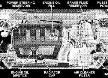
ENGINE COMPARTMENT — GASOLINE ENGINES
ONBOARD DIAGNOSTIC SYSTEM — OBD II Your vehicle is equipped with a sophisticated onboard diagnostic system called OBD II. This system monitors the performance of the emissions, engine, and automatic transmission control systems. When these systems are operating properly, your vehicle will provide excellent performance and fuel economy, as well as engine emis- sions well within current government regulations. If any of these systems require service, the OBD II system will turn on the “Malfunction Indicator Light.” It will also store diagnostic codes and other information to assist your service technician in making repairs. Al- though your vehicle will usually be drivable and not need towing, see your dealer for service as soon as possible.
MAINTAINING YOUR VEHICLE 317
CAUTION!
• Prolonged driving with the “Malfunction Indica- tor Light” on could cause further damage to the emission control system. It could also affect fuel economy and driveability. The vehicle must be serviced before any emissions tests can be per- formed. • If the “Malfunction Indicator Light” is flashing while the engine is running, severe catalytic con- verter damage and power loss will soon occur. Immediate service is required.
Loose Fuel Filler Cap Message After fuel is added, the vehicle diagnostic system can determine if the fuel filler cap is loose or improperly installed. A GASCAP message will be displayed in the instrument cluster. Tighten the gas cap until a ⬙clicking⬙
318 MAINTAINING YOUR VEHICLE
sound is heard. This is an indication that the gas cap is properly tightened. Press the odometer reset button to turn the message off. If the problem persists, the message will appear the next time the vehicle is started. This might indicate a damaged cap. If the problem is detected twice in a row, the system will turn on the Malfunction Indicator Light (MIL). Resolving the problem will turn the MIL light off.
EMISSIONS INSPECTION AND MAINTENANCE PROGRAMS In some localities, it may be a legal requirement to pass an inspection of your vehicle’s emissions control system. Failure to pass could prevent vehicle registration.
For states, which have an I/M (Inspection and Maintenance) requirement, this check verifies the following: the MIL (Malfunction Indicator Lamp)
is functioning and is not on when the engine is running, and that the OBD (On Board Diagnostic) system is ready for testing. Normally, the OBD system will be ready. The OBD system may not be ready if your vehicle was recently serviced, if you recently had a dead battery, or a battery replacement. If the OBD system should be determined not ready for the I/M test, your vehicle may fail the test. Your vehicle has a simple ignition key actuated test, which you can use prior to going to the test station. To check if your vehicle’s OBD system is ready, you must do the following: 1. Insert your ignition key into the ignition switch. 2. Turn the ignition to the ON position, but do not crank or start the engine. 3. If you crank or start the engine, you will have to start this test over.
4. As soon as you turn your key to the ON position, you will see your MIL symbol come on as part of a normal bulb check. 5. Approximately 15 seconds later, one of two things will happen:
a. The MIL will flash for about 10 seconds and then return to being fully illuminated until you turn off the ignition key or start the engine. This means that your vehicle’s OBD system is not ready and you should not proceed to the I/M station. b. The MIL will not flash at all and will remain fully illuminated until you turn off the ignition key or start the engine. This means that your vehicle’s OBD system is ready and you can proceed to the I/M station.
If your OBD system is not ready, you should see your authorized dealer or repair facility. If your vehicle was recently serviced or had a battery failure or replacement,
MAINTAINING YOUR VEHICLE 319
you may need to do nothing more than drive your vehicle as you normally would in order for your OBD system to update. A recheck with the above test routine may then indicate that the system is now ready. Regardless of whether your vehicle’s OBD system is ready or not ready, if the MIL symbol is illuminated during normal vehicle operation, you should have your vehicle serviced before going to the I/M station. The I/M station can fail your vehicle because the MIL symbol is on with the engine running.
REPLACEMENT PARTS Use of genuine Mopar威 parts for normal/scheduled maintenance and repairs is highly recommended to in- sure the designed performance. Damage or failures caused by the use of non-Mopar威 parts for maintenance and repairs will not be covered by the manufacturer’s warranty.
320 MAINTAINING YOUR VEHICLE
DEALER SERVICE Your dealer has the qualified service personnel, special tools, and equipment to perform all service operations in an expert manner. Service Manuals are available which include detailed service information for your vehicle. Refer to these manuals before attempting any procedure yourself. NOTE: systems can result against you.
Intentional tampering with emissions control in civil penalties being assessed
WARNING!
You can be badly injured working on or around a motor vehicle. Only do service work for which you have the knowledge and the proper equipment. If you have any doubt about your ability to perform a service job, take your vehicle to a competent me- chanic.
MAINTENANCE PROCEDURES The pages that follow contain the required maintenance services determined by the engineers who designed your vehicle. Besides the maintenance items for which there are fixed maintenance intervals, there are other items that should operate satisfactorily without periodic maintenance. However, if a malfunction of these items does occur, it could adversely affect the engine or vehicle performance. These items should be inspected if a malfunction is observed or suspected. Engine Oil
Checking Oil Level To assure proper engine lubrication, the engine oil must be maintained at the correct level. Check the oil level at regular intervals, such as every fuel stop.
The best time to check the engine oil level is about 5
minutes after a fully warmed engine is shut off. Do not check oil level before starting the engine after it has sat overnight. Checking engine oil level when the engine is cold will give you an incorrect reading.Engine Oil Dipstick
MAINTAINING YOUR VEHICLE 321
Checking the oil while the vehicle is on level ground and only when the engine is hot, will improve the accuracy of the oil level readings. Maintain the oil level between the range markings on the dipstick. The range markings will consist of a crosshatch zone that says SAFE or a cross- hatch zone that says MIN at the low end of the range and MAX at the high end of the range. Adding one quart of oil when the reading is at the low end of the indicated range will result in the oil level at the full end of the indicator range.
CAUTION!
Do not overfill the engine. Overfilling the engine as indicated by the range markings, as described above, on the engine oil dipstick will cause oil aeration, which can lead to loss of oil pressure and an increase in oil temperature. This could damage your engine.
322 MAINTAINING YOUR VEHICLE
Change Engine Oil Road conditions and your kind of driving affects the interval at which your oil should be changed. Check the following list to decide if any apply to you. • Day and night temperatures are below 32°F (0°C). • Stop and Go driving. • Extensive engine idling. • Driving in dusty conditions. • Short trips of less than 10 miles (16 km). • More than 50% of your driving is at sustained high • Trailer towing. • Taxi, Police or delivery service (commercial service). • Off-Road or desert operation.
speeds during hot weather, above 90°F (32°C).
If ANY of these apply to you then change your NOTE: engine oil every 3,000 miles (5 000 km) or 3 months, whichever comes first, and follow schedule “B—All Engines” of the ⬙Maintenance Schedules⬙ section of this manual. If none of these apply to you, then change your engine oil at every interval shown on schedule “A” in the mainte- nance schedule section of this manual. NOTE: Under no circumstances should oil change in- tervals exceed 6000 miles (10 000 km) or 6 months whichever comes first. Engine Oil Selection (Gasoline Engines) For best performance and maximum protection for all engines under all types of operating conditions, the manufacturer recommends engine oils that are API Cer- tified and meet the requirements of DaimlerChrysler Material Standard MS-6395.
American Petroleum Institute (API) Engine Oil Identification Symbol
This symbol means that the oil has been certified by the American Petroleum Institute (API). The manufacturer only recommends API Certified engine oils.
Engine Oil Viscosity (SAE Grade) SAE 5W-20 engine oil is recommended for all operating temperatures. This engine oil improves low tempera- ture starting and vehicle fuel economy. Your engine oil filler cap also states the recommended engine oil vis- cosity grade for your engine.
MAINTAINING YOUR VEHICLE 323
Lubricants which do not have both, the engine oil certi- fication mark and the correct SAE viscosity grade num- ber should not be used. Synthetic Engine Oils There are a number of engine oils being promoted as either synthetic or semi-synthetic. If you chose to use such a product, use only those oils that are American Petroleum Institute (API) Certified and have the recom- mended SAE viscosity grade. Follow the maintenance schedule that describes your driving type. Materials Added To Engine Oils The manufacture strongly recommends against the addi- tion of any additives (other than leak detection dyes) to the engine oil. Engine oil is an engineered product and it’s performance may be impaired by supplemental ad- ditives.
324 MAINTAINING YOUR VEHICLE
Disposing of Used Engine Oil Care should be taken in disposing of used engine oil from your vehicle. Used oil, indiscriminately discarded, can present a problem to the environment. Contact your dealer, service station, or governmental agency for advice on how and where used oil can be safely discarded in your area. Engine Oil Filter The engine oil filter should be replaced at every engine oil change. Engine Oil Filter Selection All of this manufacturers engines have a full-flow type disposable oil filter. Use a filter of this type for replace- ment. The quality of replacement filters varies consider- ably. Only high quality filters should be used to assure most efficient service. Mopar Engine Oil Filters are high quality oil filters and are recommended.
Drive Belt — Check Condition At the mileage shown in the maintenance schedules, check the drive belt for condition. Inspect the drive belt for evidence of cuts, cracks, or glazing and replace belt if any sign of damage which could result in belt failure. The belt is self-tensioning and will not need adjustment. Spark Plugs Spark plugs must fire properly to assure engine perfor- mance and emission control. New plugs should be in- stalled at the specified mileage. The entire set should be replaced if there is any malfunction due to a faulty spark plug. Refer to the Engine data Label located under the hood for the proper type of spark plug for use in your vehicle.
Catalytic Converter The catalytic converter requires the use of unleaded fuel only. Leaded gasoline will destroy the effectiveness of the catalyst as an emission control device. Under normal operating conditions, the catalytic con- verter will not require maintenance. However, it is im- portant to keep the engine properly tuned to assure proper catalyst operation and prevent possible catalyst damage.
MAINTAINING YOUR VEHICLE 325
CAUTION!
Damage to the catalytic converter can result if your vehicle is not kept in proper operating condition. In the event of engine malfunction, particularly involv- ing engine misfire or other apparent loss of perfor- mance, have your vehicle serviced promptly. Contin- ued operation of your vehicle with a severe malfunction could cause the converter to overheat, resulting in possible damage to the converter and the vehicle.
326 MAINTAINING YOUR VEHICLE
WARNING!
A hot exhaust system can start a fire if you park over materials that can burn. Such materials might be grass or leaves coming into contact with your ex- haust system. Do not park or operate your vehicle in areas where your exhaust system can contact any- thing that can burn.
In unusual situations involving grossly malfunctioning engine operation, a scorching odor may suggest severe and abnormal catalyst overheating. If this occurs, stop the vehicle, turn off the engine and allow it to cool. Service, including a tune up to manufacturers specifica- tions, should be obtained immediately. To minimize the possibility of catalyst damage:
• Do not shut off the engine or interrupt the ignition when the transaxle is in gear and the vehicle is in motion. • Do not try to start the engine by pushing or towing the • Do not idle the engine with any spark plug wires
vehicle.
disconnected for prolonged period.
Crankcase Emission Control System Proper operation of this system depends on freedom from sticking or plugging due to deposits. As vehicle mileage builds up, the PCV valve and passages may accumulate deposits. If a valve is not working properly, replace it with a new valve. DO NOT ATTEMPT TO CLEAN THE OLD PCV VALVE! Check ventilation hose for indication of damage or plugging deposits. Replace if necessary.
Fuel Filter A plugged fuel filter can cause hard starting or limit the speed at which a vehicle can be driven. Should an excessive amount of dirt accumulate in the fuel tank, frequent filter replacement may be necessary. The fuel filters are located inside the fuel tank. See your dealer for service. Air Cleaner Element (Filter) Under normal driving conditions, replace the filter at the intervals shown on Schedule “A”. If, however, you drive the vehicle frequently under dusty or severe conditions, the filter element should be inspected periodically and replaced if necessary at the intervals shown on Schedule “B”.
MAINTAINING YOUR VEHICLE 327
WARNING!
The air cleaner can provide a measure of protection in the case of engine backfire. Do not remove the air cleaner unless such removal is necessary for repair or maintenance. Make sure that no one is near the engine compartment before starting the vehicle with the air cleaner removed. Failure to do so can result in serious personal injury.
Maintenance-Free Battery You will never have to add water, nor is periodic main- tenance required.
328 MAINTAINING YOUR VEHICLE
CAUTION!
WARNING!
When servicing the battery, always reinstall the battery thermowrap. The thermowrap provides bat- tery heat protection and will extend overall battery life. Failure to reinstall the thermowrap can result in evaporative loss of the battery fluid.
Battery fluid is a corrosive acid solution and can burn or even blind you. Don’t allow battery fluid to contact your eyes, skin or clothing. Don’t lean over a battery when attaching clamps. If acid splashes in eyes or on skin, flush the area immediately with large amounts of water. Battery gas is flammable and explosive. Keep flame or sparks away from the battery. Don’t use a booster battery or any other booster source with an output greater than 12 volts. Don’t allow cable clamps to touch each other. Battery posts, terminals and related accessories con- tain lead and lead compounds. Wash hands after handling.
CAUTION!
It is essential when replacing the cables on the battery that the positive cable is attached to the positive post and the negative cable is attached to the negative post. Battery posts are marked positive (+) and negative (-) and identified on the battery case. Cable clamps should be tight on the terminal posts and free of corrosion. Apply grease to posts and clamps after tightening. If a “fast charger” is used while the battery is in the vehicle, disconnect both vehicle battery cables be- fore connecting the charger to battery. Do not use a “fast charger” to provide starting voltage as battery damage can result.
MAINTAINING YOUR VEHICLE 329
Air Conditioner Maintenance For best possible performance, your air conditioner should be checked and serviced by an Authorized Dealer at the start of each warm season. This service should include cleaning of the condenser fins and a performance test. Drive belt tension should also be checked at this time.
330 MAINTAINING YOUR VEHICLE
WARNING!
• Use only refrigerants and compressor lubricants approved by the manufacturer for your air condi- tioning system. Some unapproved refrigerants are flammable and can explode, injuring you. Other unapproved refrigerants or lubricants can cause the system to fail, requiring costly repairs. Refer to Section 3 of the Warranty Information book for further warranty information. • The air conditioning system contains refrigerant under high pressure. To avoid risk of personal injury or damage to the system, adding refrigerant or any repair requiring lines to be disconnected should be done by an experienced repairman.
Refrigerant Recovery and Recycling R-134a Air Conditioning Refrigerant is a hydrofluorocar- bon (HFC) that is endorsed by the Environmental Pro- tection Agency and is an ozone-saving product. How- ever, the manufacturer recommends that air conditioning service be performed by dealers or other service facilities using recovery and recycling equipment. NOTE: Use only manufacturer approved A/C System Sealers, Stop Leak Products, Seal Conditioners, Compres- sor Oil, or Refrigerants. Power Steering — Fluid Check Checking the power steering fluid level at a defined service interval is not required. The fluid should only be checked if a leak is suspected, abnormal noises are apparent, and/or the system is not functioning as antici- pated. Coordinate inspection efforts through a certified DaimlerChrysler Dealership.
WARNING!
Fluid level should be checked on a level surface and with the engine off to prevent injury from moving parts and to insure accurate fluid level reading. Do not overfill. Use only manufacturers recommended power steering fluid.
If necessary, add fluid to restore to the proper indicated level. With a clean cloth, wipe any spilled fluid from all surfaces. Refer to Fluids, Lubricants, and Genuine Parts for correct fluid types. Front Suspension Ball Joints There are two front suspension lower ball joints that are permanently lubricated. Inspect these ball joints when- ever under vehicle service is done. Damaged seals and their corresponding potentially damaged ball joints must be replaced.
MAINTAINING YOUR VEHICLE 331
Body Lubrication Locks and all body pivot points, including such items as seat tracks, doors, liftgate and hood hinges, should be lubricated periodically to assure quiet, easy operation and to protect against rust and wear. Prior to the appli- cation of any lubricant, the parts concerned should be wiped clean to remove dust and grit; after lubricating excess oil and grease should be removed. Particular attention should also be given to hood latching compo- nents to insure proper function. When performing other underhood services, the hood latch, release mechanism and safety catch should be cleaned and lubricated. The external lock cylinders should be lubricated twice a year, preferably in the fall and spring. Apply a small amount of a high quality lubricant such as Mopar威 Lock Cylinder Lubricant directly into the lock cylinder.
332 MAINTAINING YOUR VEHICLE
Windshield Wiper Blades Clean the rubber edges of the wiper blades and the windshield periodically with a sponge or soft cloth and a mild non abrasive cleaner or use the washer solvent. This will remove accumulations of salt, waxes or road film and help reduce streaking and smearing. Operation of the wipers on dry glass for long periods may cause deterioration of the wiper blades. Always use washer fluid when using the wipers to remove salt or dirt from a dry windshield. Avoid using the wiper blades to remove frost or ice from the windshield. make sure that they are not frozen to the glass before turning them on to avoid damaging the blade. Keep the blade rubber out of contact with petroleum products such as engine oil, gasoline, etc. Windshield Wiper Blade Replacement 1. Lift the wiper arm away from the glass.
2. Push the release tab shown in the illustration and slide the wiper blade assembly down along the arm. Gently place the wiper arm on the windshield. 3. Install the new blade assembly onto the wiper arm tip until it locks in place. Windshield Washer Reservoir The washer fluid reservoir is located in the rear of the engine compartment on the right side and should be checked for fluid level at regular intervals. Fill the reservoir with windshield washer solvent (not radiator antifreeze). Exhaust System The best protection against carbon monoxide entry into the vehicle body is a properly maintained engine exhaust system. If you notice a change in the sound of the exhaust system, or if exhaust fumes can be detected inside the vehicle, or
when the underside or rear of the vehicle is damaged; have a competent technician inspect the complete ex- haust system and adjacent body areas for broken, dam- aged, deteriorated, or mispositioned parts. Open seams or loose connections could permit exhaust fumes to seep into the passenger compartment. In addition, inspect the exhaust system each time the vehicle is raised for an oil change or lubrication. Replace as required.
WARNING!