- 2009 Hyundai Santa FE Owners Manuals
- Hyundai Santa FE Owners Manuals
- 2005 Hyundai Santa FE Owners Manuals
- Hyundai Santa FE Owners Manuals
- 2004 Hyundai Santa FE Owners Manuals
- Hyundai Santa FE Owners Manuals
- 2010 Hyundai Santa FE Owners Manuals
- Hyundai Santa FE Owners Manuals
- 2006 Hyundai Santa FE Owners Manuals
- Hyundai Santa FE Owners Manuals
- 2003 Hyundai Santa FE Owners Manuals
- Hyundai Santa FE Owners Manuals
- 2007 Hyundai Santa FE Owners Manuals
- Hyundai Santa FE Owners Manuals
- 2008 Hyundai Santa FE Owners Manuals
- Hyundai Santa FE Owners Manuals
- 2012 Hyundai Santa FE Owners Manuals
- Hyundai Santa FE Owners Manuals
- Download PDF Manual
-
How to check Use a good quality gage to check tire pressure. You can not tell if your tires are properly inflated simply by look- ing at them. Radial tires may look properly inflated even when they're underinflated. Check the tire's inflation pressure when the tires are cold. - "Cold" means your vehicle has been sitting for at least three hours or driven no more than 1 mile (1.6 km).
Remove the valve cap from the tire valve stem. Press the tire gage firm- ly onto the valve to get a pressure measurement. If the cold tire inflation pressure matches the recommended pressure on the tire and loading information label, no further adjust- ment is necessary. If the pressure is low, add air until you reach the rec- ommended amount. If you overfill the tire, release air by pushing on the metal stem in the center of the tire valve. Recheck the tire pressure with the tire gage. Be sure to put the valve caps back on the valve stems. They help prevent leaks by keeping out dirt and mois- ture.
WARNING
(cid:129) Inspect your tires frequently for proper inflation as well as wear and damage. Always use a tire pressure gauge.
(cid:129) Tires with too much or too little pressure wear unevenly caus- ing poor handling, loss of vehi- cle control, and sudden tire failure leading to accidents, injuries, and even death. The recommended cold tire pres- sure for your vehicle can be found in this manual and on the tire label located on the dri- ver's side center pillar.
(cid:129) Worn tires can cause acci- dents. Replace tires that are worn, show uneven wear, or are damaged.
(cid:129) Remember to check the pres- sure of your spare tire. HYUNDAI recommends that you check the spare every time you check the pressure of the other tires on your vehi- cle.
34
G200400AXM Tire rotation To equalize tread wear, it is recom- mended that the tires be rotated every 7,500 miles (12,000 km) or sooner if irregular wear develops. During rotation, check the tires for correct balance. When rotating tires, check for uneven wear and damage. Abnormal wear is usually caused by incorrect tire pres- sure, improper wheel alignment, out- of-balance wheels, severe braking or severe cornering. Look for bumps or bulges in the tread or side of tire. Replace the tire if you find either of these conditions. Replace the tire if fabric or cord is visible. After rotation, be sure to bring the front and rear tire pressures to specification and check lug nut tightness. Refer to “Tire and wheels” in section 8.
With a full-size spare tire (if equipped)
Without a spare tire
S2BLA790
Maintenance
Disc brake pads should be inspected for wear whenever tires are rotated.
✽✽ NOTICE Rotate radial tires that have an asymmetric tread pattern only from front to rear and not from right to left.
WARNING
(cid:129) Do not use the compact spare
tire for tire rotation.
Directional tires (if equipped)
S2BLA790A
(cid:129) Do not mix bias ply and radial ply tires under any circum- stances. This may cause unusual handling characteris- tics that could result in death, severe injury, or property damage.
CBGQ0707A
7 35
Maintenance
G200500AUN Wheel alignment and tire balance The wheels on your vehicle were aligned and balanced carefully at the factory to give you the longest tire life and best overall performance. In most cases, you will not need to have your wheels aligned again. However, if you notice unusual tire wear or your vehicle pulling one way or the other, the alignment may need to be reset. If you notice your vehicle vibrating when driving on a smooth road, your wheels may need to be rebalanced.
CAUTION
Improper wheel weights can damage your vehicle's alu- minum wheels. Use only approved wheel weights.
36
Tread wear indicator
OEN076053
G200600BFD Tire replacement If the tire is worn evenly, a tread wear indicator will appear as a solid band across the tread. This shows there is less than 1/16 in. (1.6 mm) of tread left on the tire. Replace the tire when this happens. Do not wait for the band to appear across the entire tread before replac- ing the tire.
WARNING - Replacing
tires
(cid:129) Driving on worn-out tires is very hazardous and will reduce braking effectiveness, steering accuracy, and trac- tion.
(cid:129) Your vehicle is equipped with tires designed to provide for safe ride and handling capa- bility. Do not use a size and type of tire and wheel that is different from the one that is originally installed on your vehicle. It can affect the safety and performance of your vehi- cle, which could lead to han- dling failure or rollover and serious injury. When replacing the tires, be sure to equip all four tires with the tire and wheel of the same size, type, tread, brand and load-carrying capacity.
(Continued)
G200601AUN Compact spare tire replacement (if equipped) A compact spare tire has a shorter tread life than a regular size tire. Replace it when you can see the tread wear indicator bars on the tire. The replacement compact spare tire should be the same size and design tire as the one provided with your new vehicle and should be mounted on the same compact spare tire wheel. The compact spare tire is not designed to be mounted on a regular size wheel, and the compact spare tire wheel is not designed for mount- ing a regular size tire.
(Continued) (cid:129) The use of any other tire size or type may seriously affect ride, handling, ground clear- ance, stopping distance, body to tire clearance, snow tire clearance, and speedometer reliability.
(cid:129) It is best to replace all four tires at the same time. If that is not possible, or necessary, then replace the two front or two rear tires as a pair. Replacing just one tire can seriously affect your vehicle’s handling.
(cid:129) The ABS works by comparing the speed of the wheels. Tire size can affect wheel speed. When replacing tires, all 4 tires must use the same size origi- nally supplied with the vehicle. Using tires of a different size can cause the ABS (Anti-lock Brake System) and ESC (Electronic Stability Control) (if equipped) to work irregularly.
Maintenance
G200700AUN Wheel replacement When replacing the metal wheels for any reason, make sure the new wheels are equivalent to the original factory units in diameter, rim width and offset.
WARNING
A wheel that is not the correct size may adversely affect wheel and bearing life, braking and stopping abilities, handling characteristics, ground clear- ance, body-to-tire clearance, snow clearance, speedometer and odometer cal- ibration, headlight aim and bumper height.
chain
7 37
Maintenance
G200800AUN Tire traction Tire traction can be reduced if you drive on worn tires, tires that are improperly inflated or on slippery road surfaces. Tires should be replaced when tread wear indicators appear. To reduce the possibility of losing control, slow down whenever there is rain, snow or ice on the road.
G200900AUN Tire maintenance In addition to proper inflation, correct wheel alignment helps to decrease tire wear. If you find a tire is worn unevenly, have your dealer check the wheel alignment. When you have new tires installed, make sure they are balanced. This will increase vehicle ride comfort and tire life. Additionally, a tire should always be rebalanced if it is removed from the wheel.
38
5,6
I030B04JM
information
G201000AUN Tire sidewall labeling identifies and This describes the fundamental charac- teristics of the tire and also provides the tire identification number (TIN) for safety standard certification. The TIN can be used to identify the tire in case of a recall.
G201001AUN 1.Manufacturer or brand name Manufacturer or Brand name is shown.
G201002ACM 2.Tire size designation A tire’s sidewall is marked with a tire size designation. You will need this information when selecting replace- ment tires for your car. The following explains what the letters and num- bers in the tire size designation mean. Example tire size designation: (These numbers are provided as an example only; your tire size designa- tor could vary depending on your vehicle.) P235/60R18 102H
P - Applicable vehicle type (tires marked with the prefix “P’’ are intended for use on passenger vehicles or light trucks; however, not all tires have this marking).
235 - Tire width in millimeters. 60 - Aspect ratio. The tire’s section height as a percentage of its width.
R - Tire construction code (Radial). 18 - Rim diameter in inches.
102 - Load Index, a numerical code associated with the maximum load the tire can carry.
H - Speed Rating Symbol. See the speed rating chart in this section for additional information.
Wheel size designation Wheels are also marked with impor- tant information that you need if you ever have to replace one. The follow- ing explains what the letters and numbers in the wheel size designa- tion mean.
Example wheel size designation: 7.0JX18
7.0 - Rim width in inches. J - Rim contour designation. 18 - Rim diameter in inches.
Tire speed ratings The chart below lists many of the dif- ferent speed ratings currently being used for passenger cars. The speed rating is part of the tire size designa- tion on the sidewall of the tire. This symbol corresponds to that tire's designed maximum safe operating speed.
Speed Rating Symbol
Maximum Speed
112 mph (180 km/h)
118 mph (190 km/h)
130 mph (210 km/h)
149 mph (240 km/h)
Above 149 mph (240 km/h)
Maintenance
G201003AEN 3.Checking tire life
(TIN :Tire Identification Number)
Any tires that are over 6 years, based on the manufacturing date, tire strength and performance, decline with age naturally (even unused spare tires). Therefore, the tires (including the spare tire) should be replaced by new ones. You can find the manufacturing date on the tire sidewall (possibly on the inside of the wheel), displaying the DOT Code. The DOT Code is a series of num- bers on a tire consisting of numbers and English letters. The manufactur- ing date is designated by the last four digits (characters) of the DOT code.
DOT : XXXX XXXX OOOO The front part of the DOT means a plant code number, tire size and tread pattern and the last four num- bers indicate week and year manu- factured. For example: DOT XXXX XXXX 1609 represents that the tire was produced in the 16th week of 2009.
7 39
Maintenance
WARNING - Tire age
Tires degrade over time, even when they are not being used. Regardless of the remaining tread, it is recommended that tires generally be replaced after six (6) years of normal service. Heat caused by not climates or frequent high loading condi- tions can accelerate the aging process. Failure to follow this Warning can result in sudden tire failure, which could lead to a loss of control and an acci- dent involving serious injury or death.
G201004AUN 4.Tire ply composition and material The number of layers or plies of rub- ber-coated fabric are in the tire. Tire manufacturers also must indicate the materials in the tire, which include steel, nylon, polyester, and others. The letter "R" means radial ply con- struction; the letter "D" means diago- nal or bias ply construction; and the letter "B" means belted-bias ply con- struction.
40
G201005AUN 5.Maximum permissible inflation
pressure
This number is the greatest amount of air pressure that should be put in the tire. Do not exceed the maximum permissible inflation pressure. Refer to the Tire and Loading Information label inflation pressure.
for recommended
G201006AUN 6.Maximum load rating This number indicates the maximum load in kilograms and pounds that can be carried by the tire. When replacing the tires on the vehicle, always use a tire that has the same load rating as the factory installed tire.
the
G201007BUN 7.Uniform tire quality grading Quality grades can be found where applicable on tire sidewall between tread shoulder and maxi- mum section width. For example: TREADWEAR 200 TRACTION AA TEMPERATURE A
Tread wear The tread wear grade is a compara- tive rating based on the wear rate of the tire when tested under controlled conditions on a specified govern- ment test course. For example, a tire graded 150 would wear one-and-a- half times (1½) as well on the gov- ernment course as a tire graded 100. The relative performance of tires depends upon the actual conditions of their use, however, and may depart significantly from the norm because of variations in driving habits, service practices and differ- ences in road characteristics and cli- mate. These grades are molded on the side-walls of passenger vehicle tires. The tires available as standard or optional equipment on your vehicles may vary with respect to grade.
Traction - AA, A, B & C The traction grades, from highest to lowest, are AA, A, B and C. Those grades represent the tires ability to stop on wet pavement as measured under controlled conditions on spec- ified government test surfaces of asphalt and concrete. A tire marked C may have poor traction perform- ance.
WARNING
The traction grade assigned to this tire is based on straight- ahead braking traction tests, and does not include accelera- tion, cornering, hydroplaning, or peak traction characteristics.
Temperature -A, B & C The temperature grades are A (the highest), B and C representing the tire’s resistance to the generation of heat and its ability to dissipate heat when tested under controlled condi- tions on a specified indoor laboratory test wheel. Sustained high temperature can cause the material of the tire to degenerate and reduce tire life, and excessive temperature can lead to sudden tire failure. Grades B and A represent higher levels of perform- ance on the laboratory test wheel than the minimum required by the law.
WARNING - Tire
temperature
The temperature grade for this tire is established for a tire that is properly inflated and not overloaded. Excessive speed, underinflation, or excessive loading, either separately or in combination, can cause heat build-up and possible sudden tire failure. This can cause loss of vehicle control and serious injury or death.
Maintenance
G201100AEN Tire terminology and definitions Air Pressure: The amount of air inside the tire pressing outward on the tire. Air pressure is expressed in pounds per square inch (psi) or kilo- pascal (kPa). Accessory Weight: This means the combined weight of optional acces- sories. Some examples of optional accessories are, automatic transaxle power seats, and air conditioning. Aspect Ratio: The relationship of a tire's height to its width. Belt: A rubber coated layer of cords that is located between the plies and the tread. Cords may be made from steel or other reinforcing materials. Bead: The tire bead contains steel wires wrapped by steel cords that hold the tire onto the rim. Bias Ply Tire: A pneumatic tire in which the plies are laid at alternate angles less than 90 degrees to the centerline of the tread.
7 41
Maintenance
Cold Tire Pressure: The amount of air pressure in a tire, measured in pounds per square inch (psi) or kilo- pascals (kPa) before a tire has built up heat from driving. Curb Weight: This means the weight of a motor vehicle with standard and optional equipment including the maximum capacity of fuel, oil and coolant, but without passengers and cargo. DOT Markings: A code molded into the sidewall of a tire signifying that the tire is in compliance with the U.S. Department of Transportation motor vehicle safety standards. The DOT code includes the Tire Identification Number (TIN), an alphanumeric des- ignator which can also identify the tire manufacturer, production plant, brand and date of production. GVWR: Gross Vehicle Weight Rating GAWR FRT: Gross Axle Weight Rating for the Front Axle. GAWR RR: Gross Axle Weight Rating for the Rear axle.
42
Intended Outboard Sidewall: The side of an asymmetrical tire, that must always face outward when mounted on a vehicle. Kilopascal (kPa): The metric unit for air pressure. Load Index: An assigned number ranging from 1 to 279 that corre- sponds to the load carrying capacity of a tire. Maximum Inflation Pressure: The maximum air pressure to which a cold tire may be inflated. The maxi- mum air pressure is molded onto the sidewall. Maximum Load Rating: The load rating for a tire at the maximum per- missible inflation pressure for that tire. Maximum Loaded Vehicle Weight: The sum of curb weight; accessory weight; vehicle capacity weight; and production options weight. Normal Occupant Weight: The number of occupants a vehicle is designed to seat multiplied by 150
pounds (68 kg).Occupant Distribution: Designated seating positions. Outward Facing Sidewall: The side of a asymmetrical tire that has a par- ticular side that faces outward when mounted on a vehicle. The outward facing sidewall bears white lettering or bears manufacturer, brand, and/or model name molding that is higher or deeper than the same moldings on the inner facing sidewall. Passenger (P-Metric) Tire: A tire used on passenger cars and some light duty trucks and multipurpose vehicles. Recommended Inflation Pressure: Vehicle manufacturer's recommend- ed tire inflation pressure and shown on the tire placard. Radial Ply Tire: A pneumatic tire in which the ply cords that extend to the beads are laid at 90 degrees to the centerline of the tread. Rim: A metal support for a tire and upon which the tire beads are seat- ed. Sidewall: The portion of a tire between the tread and the bead.
Speed Rating: An alphanumeric code assigned to a tire indicating the maximum speed at which a tire can operate. Traction: The friction between the tire and the road surface. The amount of grip provided. Tread: The portion of a tire that comes into contact with the road. Treadwear Indicators: Narrow bands, sometimes called "wear bars," that show across the tread of a tire when only 2/32 inch of tread remains. UTQGS: Uniform Tire Quality Grading Standards, a tire information system that provides consumers with ratings for a tire's traction, tempera- ture and treadwear. Ratings are determined by tire manufacturers using government testing proce- dures. The ratings are molded into the sidewall of the tire. Vehicle Capacity Weight: The num- ber of designated seating positions multiplied by 150 lbs. (68 kg) plus the rated cargo and luggage load.
Vehicle Maximum Load on the Tire: Load on an individual tire due to curb and accessory weight plus maximum occupant and cargo weight. Vehicle Normal Load on the Tire: Load on an individual tire that is determined by distributing to each axle its share of the curb weight, accessory weight, and normal occu- pant weight and driving by 2. Vehicle Placard: A label permanent- ly attached to a vehicle showing the original equipment tire size and rec- ommended inflation pressure.
All season tires HYUNDAI specifies all season tires on some models to provide good performance for use all year round, including snowy and icy road condi- tions. All season tires are identified by ALL SEASON and/or M+S (Mud and Snow) on the tire sidewall. Snow tires have better snow traction than all season tires and may be more appropriate in some areas.
Maintenance
Summer tires HYUNDAI specifies summer tires on some models to provide superior performance on dry roads. Summer tire performance is substantially reduced in snow and ice. Summer tires do not have the tire traction rat- ing M+S (Mud and Snow) on the tire side wall. if you plan to operate your vehicle in snowy or icy conditions. HYUNDAI recommends the use of snow tires or all season tires on all four wheels.
Snow tires If you equip your car with snow tires, they should be the same size and have the same load capacity as the original tires. Snow tires should be installed on all four wheels; other- wise, poor handling may result. Snow tires should carry 4 psi (28
kPa) more air pressure than the pressure recommended for the stan- dard tires on the tire label on the dri- ver's side of the center pillar, or up to the maximum pressure shown on the tire sidewall, whichever is less.7 43
Maintenance
Do not drive faster than 75 mph (120
km/h) when your car is equipped with snow tires.Tire chains Tire chains, if necessary, should be installed on the drive wheels as fol- lows. 2WD : Front wheels AWD : All four wheels
If a full set of chains is not available for a AWD vehicle, chains may be installed on the front wheels only.
Be sure that the chains are installed in accordance with the manufactur- er's instructions. To minimize tire and chain wear, do not continue to use tire chains when they are no longer needed.
WARNING - Snow or ice
(cid:129) When driving on roads cov- ered with snow or ice, drive at less than 20 mph (30 km/h).
(cid:129) Use the SAE “S” class or wire
chains.
(cid:129) If you hear noise caused by chains contacting the body, retighten the chain to avoid contact with the vehicle body. (cid:129) To prevent body damage, retighten the chains after driv- ing 0.3~0.6 miles (0.5~1.0 km). (cid:129) Do not use tire chains on vehicles equipped with alu- minum wheels. In unavoid- able circumstance, use a wire type chain.
(cid:129) Use wire chains less than 0.59
inches (15mm) to prevent damage to the chain’s con- nection.44
Radial-ply tires Radial-ply tires provide improved tread life, road hazard resistance and smoother high speed ride. The radi- al-ply tires used on this vehicle are of belted construction, and are selected to complement the ride and handling characteristics of your vehicle. Radial-ply tires have the same load carrying capacity, as bias-ply or bias belted tires of the same size, and use the same recommended inflation pressure. Mixing of radial-ply tires with bias-ply or bias belted tires is not recommended. Any combina- tions of radial-ply and bias-ply or bias belted tires when used on the same vehicle will seriously deteriorate vehicle handling. The best rule to fol- low is: Identical radial-ply tires should always be used as a set of four. Longer wearing tires can be more susceptible to irregular tread wear. It is very important to follow the tire rotation interval shown in this section to achieve the tread life potential of these tires. Cuts and punctures in radial-ply tires are repairable only in the tread area, because of sidewall flexing. Consult your tire dealer for radial-ply tire repairs.
Maintenance
This vehicle has 2 (or 3) fuse panels, one located in the driver’s side panel bolster, the other in the engine compartment near the battery. If any of your vehicle’s lights, acces- sories, or controls do not work, check the appropriate circuit fuse. If a fuse has blown, the element inside the fuse will be melted. If the electrical system does not work, first check the driver’s side fuse panel. Always replace a blown fuse with one of the same rating. If the replacement fuse blows, this indi- cates an electrical problem. Avoid using the system involved and immediately consult an authorized HYUNDAI dealer. Three kinds of fuses are used:blade type for lower amperage rating, cartridge type, and fusible link for higher amperage rat- ings.
WARNING - Fuse replace-
ment
(cid:129) Never replace a fuse with any- thing but another fuse of the same rating.
(cid:129) A higher capacity fuse could cause damage and possibly a fire.
(cid:129) Never install a wire instead of the proper fuse - even as a temporary repair. It may cause extensive wiring damage and a possible fire.
CAUTION
Do not use a screwdriver or any other metal object to remove fuses because it may cause a short circuit and damage the system.
FUSES Blade type
Normal
Blown
Cartridge type
Normal
Blown
Fusible link
Normal
Blown
1VQA4037
G210000AFD A vehicle’s electrical system is protected from electrical overload damage by fuses.
7 45
Maintenance
If the headlights or other electrical com- ponents do not work and the fuses are OK, check the fuse block in the engine compartment. If a fuse is blown, it must be replaced.
OCM054002
G210100AUN Inner panel fuse replacement 1. Turn the ignition switch and all other
switches off.
2. Open the fuse panel cover.
OCM070021
3. Pull the suspected fuse straight out. Use the removal tool provided in the engine compartment fuse panel.4. Check the removed fuse; replace it if it
is blown.
5. Push in a new fuse of the same rating, and make sure it fits tightly in the clips. If it fits loosely, consult an authorized HYUNDAI dealer. If you do not have a spare, use a fuse of the same rating from a circuit you may not need for operating the vehicle, such as the cigar lighter fuse.
46
✽✽ NOTICE • If the memory fuse is pulled up from the fuse panel, the warning chime, audio, clock and interior lamps, etc., will not operate. Some items must be reset after replacement. Refer to “Battery” in this section.
• Even though the memory fuse is pulled up, the battery can still be dis- charged by operation of the head- lights or other electrical devices.
Maintenance
OCM070023
G210200AFD Engine compartment panel fuse replacement 1. Turn the ignition switch and all other
switches off.
2. Remove the fuse box cover by press-
ing the tap and pulling up.
7 47
OCM070022
G210101AXM Memory fuse (SHUNT connector) Your vehicle is equipped with a memory fuse (SHUNT connector) to prevent bat- tery discharge if your vehicle is parked without being operated for prolonged periods. Use the following procedures before parking the vehicle for prolonged periods. 1. Turn off the engine. 2. Turn off the headlights and tail lights. 3. Open the driver’s side panel cover and pull out the memory fuse (SHUNT connector).
✽✽ NOTICE If the main fuse is blown, consult an Authorized HYUNDAI Dealer.
Maintenance
3. Check the removed fuse; replace it if it is blown. To remove or insert the fuse, use the fuse puller in the engine com- partment fuse panel.
4. Push in a new fuse of the same rating, and make sure it fits tightly in the clips. If it fits loosely, consult an authorized HYUNDAI dealer.
CAUTION
After checking the fuse box in the engine compartment, securely install the fuse box cover. If not, electrical failures may occur from water leaking in.
48
OCM070025
G210201ACM Main fuse If the main fuse is blown, it must be removed as follows: 1. Disconnect the negative battery cable. 2. Remove the bolts shown in the picture
above.
3. Replace the fuse with a new one of the
same rating.
4. Reinstall in the reverse order of
removal.
G210300AFD Fuse/Relay panel description Inside the fuse/relay box covers, you can find the fuse/relay label describing fuse/relay name and capacity.
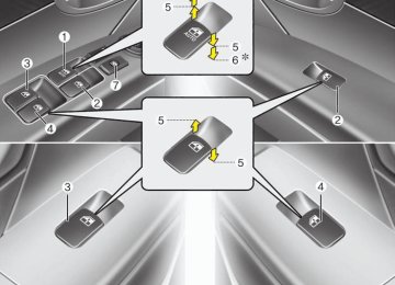
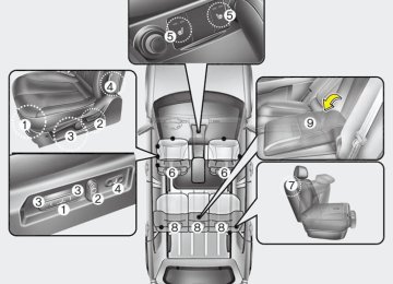
Driver’s side panel
Engine compartment
✽✽ NOTICE Not all fuse panel descriptions in this manual may be applicable to your vehi- cle. It is accurate at the time of printing. When you inspect the fuse box on your vehicle, refer to the fuse box label.
Maintenance
OCM070026/OCM070027
7 49
Maintenance
Driver's side fuse panel
Description
Fuse rating
START
P/WDW LH P/WDW RH
S/ROOF P/SEAT
SAFETY PWR
MIRR HTD A/BAG 2
A/BAG 1ROOM LP
A/CON
AC INVERTER
P/AMP
P/OUTLET CTR
P/OUTLET C/LIGHTER
DR LOCK
A/BAG IND
ESC SW
50
10A 25A 25A 20A 30A 25A 10A 15A 15A
10A
10A
25A 30A 15A 25A 15A
20A
10A
10A
Protected component
Burglar Alarm Relay Power Window Main Switch, Rear Power Window Switch LH Power Window Main Switch, Passenger Power Window Switch, Rear Power Window Switch RH Sunroof Motor Driver/Passenger Seat Manual Switch, Driver Lumbar Support Switch Safety Power Window Module Rear Defogger Switch, Driver/Passenger Power Outside Mirror Digital Clock & Telltail SRS Control Module, PODS Module Instrument Cluster (IND.), Driver/Passenger Door Lamp, MAP Lamp, Room Lamp, Cargo Lamp, Driver/Passenger Vanity Switch A/C Control Module, Cluster Ionizer, Incar Sensor, Sunroof Motor, Electro Chromic Mirror, Blower Relay, GM02 (Ground), Home Link AC Inverter Module Amp Center Power Outlet Front Power Outlet & Cigarette Lighter, Rear Power Outlet Front Power Outlet & Cigarette Lighter Door Lock/Unlock Relay, ICM Relay Box (Key Lock/Unlock Relay), BCM, Driver/Passenger Door Lock Actuator, Tail Gate Lock Actuator, Rear Door Lock Actuator LH/RH, GM01 (Ground) Instrument Cluster (IND.) ESC Switch, Steering Angle Sensor, ICM Relay Box (Sub Start Relay), Driver/Passenger Seat Warmer Control Module, Multifunction Switch (Remote Control)
Description
Fuse rating
Protected component
Maintenance
T/SIG
S/WARMER
DRL
HAZARD
RR WIPER A/CON SW
CLUSTER
BCM 1
RR A/CON
TPMS BCM 2
AUDIO 2
BLOWER STOP LP PDM 1
BCM 3
CLOCK AUDIO 1ATM PDM 2
POWER CONNECTOR10A 15A 15A
15A
15A 10A
10A
10A 15A 10A 10A
10A
30A 15A 20A 10A 15A 15A 10A 15A
Hazard Switch Driver/Passenger Seat Warmer Control Module ICM Relay Box (DRL Relay) Hazard Relay, Hazard Switch, BCM, Instrument Cluster (IND.), Multifunction Switch (Light), Rear Combination Lamp (OUT) LH/RH, Head Lamp LH/RH Rear Wiper Relay, Rear Wiper Motor, Multifunction Switch (Wiper) A/C Control Module Alternator, Instrument Cluster (IND.), BCM, A/V & Navigation Head Unit, Tire Pressure Monitoring Module, DVD Module BCM Not Used Tire Pressure Monitoring Module Rheostat, BCM, Instrument Cluster (MICOM), AC Inverter Switch, AC Inverter Module Audio, A/V & Navigation Head Unit, BCM, DVD Module, Digital Clock & Telltale, Power Outside Mirror Switch Blower Relay, Blower Motor, A/CON SW 10A Stop Lamp Switch Not Used BCM, Ignition Key ILL. & Door Warning Switch, Security Indicator A/C Control Module, Data Link Connector, Digital Clock & Telltail Audio, A/V & Navigation Head Unit, DVD Module Sport Mode Switch, Key Solenoid Not Used FUSE - ROOM LP 15A, CLOCK 15A, AUDIO 1 15A, BCM 3 10A
7 51
Maintenance
Engine compartment
Description
Fuse rating
Protected component
175A
30A 40A 40A 50A 20A 40A 40A 50A 40A
50A
40A 40A 15A 30A
15A 15A
FUSIBLE LINK - BLR, B+ 2, P/WDW, ESC 1, ESC 2 FUSE - DEICER, RR HTD, A/CON, FR FOG, H/LP LO LH, H/LP LO RH Trailer Power Outlet Ignition Switch (ACC, IG 1) Multipurpose Check Connector, ESC Control Module Condenser Fan Relay (High) ESC Control Module FUSE - BLOWER Power Window Relay, FUSE - SAFETY PWR FUSE - P/SEAT, TPMS, RR A/CON, S/WARMER, S/ROOF, PDM 2, P/AMP, AC INVERTER, DRL Ignition Switch (START, IG 2), Start Relay FUSE - DR LOCK, HAZARD, ATM, PDM 1, STOP LP, POWER CONNECTOR (BCM 3, CLOCK ROOM LP, AUDIO 1) Condenser Fan Relay (Low) Engine Control Relay Front Wiper Deicer Relay Rear Defogger Relay Head Lamp Low Relay (RH) Horn Relay
ALT
BATT IGN 1
ESC 1CON FAN 2
ESC 2
BLRP/WDW
B+ 2
IGN 2B+ 1
CON FAN 1
ECU MAIN DEICER RR HTDH/LP LO RH
HORN
52
Maintenance
Description
Fuse rating
Protected component
10
11
12
13H/LP LO LH H/LP HI IND
A/CON
ATM
TAIL LP RH
FR FOG
15A 10A
10A 15A
10A 10A
Head Lamp Low Relay (LH) Instrument Cluster (High Beam IND.) A/CON Relay AWD ECM, PCM (G4KE), Back-Up Lamp Relay Rear Combination Lamp (In)/(Out) RH, Head Lamp RH, Glove Box Lamp, Illuminations Front Fog Lamp Relay
14
SENSOR 3
15A
G4KE - Injector #1~#4, Canister Close Valve Canister Purge Control Solenoid Valve G6DC - PCM, Oil Control Valve #1/2 (Exhaust/Intake) Canister Purge Control Solenoid Valve Canister Close Valve, Variable Intake Manifold Valve #1/2
15
16
17
1819
20
21
22
23
24TAIL LP LH FUEL PUMP FR WIPER
TCU
ESC
COOLING B/UP LP
H/LP ECU
H/LP HI
10A 15A 25A 15A
10A
10A 10A 10A 10A 20A
License Lamp, Rear Combination Lamp (In) LH, Rear Combination Lamp (Out) LH, Head Lamp LH Fuel Pump Relay Front Wiper Relay, Front Wiper Motor, Multifunction Switch (Wiper) PCM, Battery Sensor Multipurpose Check Connector (G6DC), AWD ECM, ESC Control Module, Yaw Rate Sensor, Stop Lamp Switch (G6DC) Condenser Fan Relay (G6DC) Back-Up Lamp Relay, Back-Up Lamp Switch (G4KE) Head Lamp Low Relay (LH/RH), Front Fog Lamp Relay, Head Lamp High Relay PCM, Alternator (G6DC), Transaxle Range Switch Head Lamp High Relay
7 53
Maintenance
Description
Fuse rating
Protected component
25
SENSOR 1
10A
G4KE - Stop Lamp Switch, Immobilizer Module, A/CON Relay, Fuel Pump Relay, Condenser Fan Relay (Low/High), Crankshaft Position Sensor, Oil Control Valve #1/2, Camshaft Position Sensor #1/2, Oxygen Sensor (Up), Variable Intake Manifold Valve G6DC - PCM, A/CON Relay, Fuel Pump Relay, Injector #1~#6, Immobilizer Module
26
27
28
29
30
31
32SENSOR 2
IGN COIL
SPARE SPARE SPARE SPARE SPARE
15A
20A
10A 15A 20A 25A 30A
G4KE - PCM, Oxygen Sensor (Down) G6DC - PCM, Oxygen Sensor #1~#4, Variable Charge Motion Actuator G4KE - Condenser, Ignition Coil #1~#4
G6DC - Condenser #1/2, Ignition Coil #1~#654
Maintenance
✽✽ NOTICE After heavy, driving rain or washing, headlight and taillight lenses could appear frosty. This condition is caused by the temperature difference between the lamp inside and outside. This is similar to the condensation on your windows inside your vehicle during the rain and doesn’t indicate a problem with your vehicle. If the water leaks into the lamp bulb circuitry, have the vehicle checked by an authorized HYUNDAI dealer.
CAUTION
If you don’t have necessary tools, the correct bulbs and the expertise, consult an authorized HYUNDAI dealer.In many cases,it is difficult to replace vehicle light bulbs because other parts of the vehicle must be removed before you can get to the bulb. This is especially true if you have to remove the head- light assembly to get to the bulb(s). Removing/installing the headlight assembly can result in damage to the vehicle.
LIGHT BULBS G220000AFD
WARNING - Working on
the lights
Prior to working on the light, firmly apply the parking brake, ensure that the ignition switch is turned to the “LOCK” position and turn off the lights to avoid sudden move- ment of the vehicle and burning your fingers or receiving an electric shock.
Use only the bulbs of the specified wattage.
CAUTION
Be sure to replace the burned-out bulb with one of the same wattage rating. Otherwise, it may cause damage to the fuse or electric wiring system.
7 55
Maintenance
(Continued) (cid:129) If a bulb becomes damaged or cracked, replace it immediately and carefully dispose of it.
(cid:129) Wear eye protection when chang- ing a bulb. Allow the bulb to cool down before handling it.
OCM070029
OHD076046
G220100AUN Headlight, position light, turn sig- nal light, front fog light bulb replacement (1) Headlight (High) (2) Headlight (Low) (3) Position light / Front turn signal light
(Front side marker)
(4) Front fog light (if equipped)
G220101ACM Headlight bulb
WARNING - Halogen bulbs (cid:129) Halogen bulbs contain pressur- ized gas that will produce flying pieces of glass if broken.
(cid:129) Always handle them carefully, and avoid scratches and abra- sions. If the bulbs are lit, avoid contact with liquids. Never touch the glass with bare hands. Residual oil may cause the bulb to overheat and burst when lit. A bulb should be operated only when installed in a headlight.
(Continued)
56
OCM070050L
1. Open the hood. 2. Loosen the retaining bolts and remove the headlight assembly from the body of the vehicle.
3. Disconnect the power connector from
the back of the headlight assembly.
OCM070051L 4. Remove the headlight bulb cover by
turning it counterclockwise.
5. Disconnect the headlight bulb socket-
connector.
6. Unsnap the headlight bulb retaining wire by depressing the end and push- ing it upward (High beam).
7. Remove the bulb from the headlight
assembly.
Maintenance
8. Install a new headlight bulb and snap the headlight bulb retaining wire into position by aligning the wire with the groove on the bulb (High beam).
9. Connect the headlight bulb socket
connector.
10. Install the headlight bulb cover by
turning it clockwise.
11. Connect the power connector to the
back of the headlight assembly.
12. Reinstall the headlight assembly to
the body of the vehicle.
✽✽ NOTICE If the headlight aiming adjustment is necessary after the headlight assembly is reinstalled, consult an authorized HYUNDAI dealer.
7 57
Maintenance
3. Insert a new bulb by inserting it into the socket and rotating it until it locks into place.
4. Install the socket in the assembly by aligning the tabs on the socket with the slots in the assembly. Push the socket into the assembly and turn the socket clockwise.
OCM055014L/H
Turn signal light/Position light 1. Remove the socket from the assembly by turning the socket counterclockwise until the tabs on the socket align with the slots on the assembly.
2. Remove the bulb from the socket by pressing it in and rotating it counter- clockwise until the tabs on the bulb align with the slots in the socket. Pull the bulb out of the socket
58
OXM079053L
Front fog light bulbs (if equipped) 1. Remove the front bumper under cover. 2. Reach your hand into the back of the
front bumper.
3. Disconnect the power connector from
the socket.
4. Remove the bulb-socket from the housing by turning the socket counter clockwise until the tabs on the socket align with the slots on the housing.
5. Install the new bulb-socket into the housing by aligning the tabs on the socket with the slots in the housing. Push the socket into the housing and turn the socket clockwise.
6. Connect the power connector to the
socket.
7. Reinstall the front bumper under cover.
OCM070033
Rear combination light bulb replacement (1) Rear turn signal light (2) Stop and tail light (3) Tail light (4) Back-up light (5) Rear side marker
Maintenance
OCM070052N
OCM055026
Outside light 1. Open the tailgate. 2. Remove the service cover using a flat-
blade screwdriver.
3. Loosen the light assembly retaining
nuts with a wrench.
4. Remove the rear combination light assembly from the body of the vehicle.
7 59
Maintenance
5. Remove the socket from the assembly by turning the socket counterclockwise until the tabs on the socket align with the slots on the assembly.
6. Remove the bulb from the socket by pressing it in and rotating it counter- clockwise until the tabs on the bulb align with the slots in the socket. Pull the bulb out of the socket. (Side marker : Remove the bulb from the socket by pulling it out)
7. Insert a new bulb by inserting it into the socket and rotating it until it locks into place.
8. Install the socket in the assembly by aligning the tabs on the socket with the slots in the assembly. Push the socket into the assembly and turn the socket clockwise.
9. Reinstall the light assembly to the
body of the vehicle.
60
4. Remove the bulb from the socket by pressing it in and rotating it counter- clockwise until the tabs on the bulb align with the slots in the socket. Pull the bulb out of the socket. (Back-up light : Remove the bulb from the cock- et by pulling it out)
5. Insert a new bulb by inserting it into the socket and rotating it until it locks into place.
6. Install the socket in the assembly by aligning the tabs on the socket with the slots in the assembly. Push the socket into the assembly and turn the socket clockwise.
7. Install the service cover by putting it
into the service hole.
OCM070037
OCM070038
Inside light 1. Open the tailgate. 2. Remove the service cover using a flat-
blade screwdriver.
3. Remove the socket from the assembly by turning the socket counterclockwise until the tabs on the socket align with the slots on the assembly.
Maintenance
OCM070046
OCM055036
High mounted stop light replacement If the light does not operate, have the vehicle checked by an authorized HYUNDAI dealer.
License plate light bulb replace- ment 1. Loosen the lens retaining screws with
a philips head screwdriver.
2. Remove the lens. 3. Remove the bulb. 4. Install a new bulb. 5. Reinstall the lens securely with the
lens retaining screws.
OCM040134
Door courtesy lamp bulb replace- ment (if equipped) If the light does not operate, have the vehicle checked by an authorized HYUNDAI dealer.7 61
Maintenance
Map lamp
Luggage room lamp
Room lamp
Vanity mirror lamp
Glove box lamp
OXM079044/OXM079041
OCM070049L/OCM055033/OCM070045
62
G220600AUN Interior light bulb replacement 1. Using a flat-blade screwdriver, gently pry the lens from the interior light housing.
2. Remove the bulb by pulling it straight
out.
WARNING
Prior to working on the Interior Lights, ensure that the “OFF” but- ton is depressed to avoid burning your fingers or receiving an electric shock.
3. Install a new bulb in the socket. 4. Align the lens tabs with the interior light housing notches and snap the lens into place.
CAUTION
Use care not to dirty or damage lens,lens tab,and plastic housings.
APPEARANCE CARE Exterior care G230101AUN Exterior general caution It is very important to follow the label directions when using any chemical cleaner or polish. Read all warning and caution statements that appear on the label.
G230102CUN Finish maintenance Washing To help protect your vehicle’s finish from rust and deterioration, wash it thoroughly and frequently at least once a month with lukewarm or cold water. If you use your vehicle for off-road driv- ing, you should wash it after each off- road trip. Pay special attention to the removal of any accumulation of salt, dirt, mud, and other foreign materials. Make sure the drain holes in the lower edges of the doors and rocker panels are kept clear and clean. Insects, tar, tree sap, bird droppings, industrial pollution and similar deposits can damage your vehicle’s finish if not removed immediately. Even prompt washing with plain water may not completely remove all these deposits. A mild soap, safe for use on painted sur- faces, may be used. After washing, rinse the vehicle thor- oughly with lukewarm or cold water. Do not allow soap to dry on the finish.
Maintenance
CAUTION
(cid:129) Do not use strong soap,chemical detergents or hot water, and do not wash the vehicle in direct sunlight or when the body of the vehicle is warm.
(cid:129) Be careful when washing the side
windows of your vehicle. Especially, with high-pressure water.Water may leak through the windows and wet the interior.
(cid:129) To prevent damage to the plastic parts,do not clean with chemical solvents or strong detergents.
WARNING - Wet brakes
After washing the vehicle, test the brakes while driving slowly to see if they have been affected by water. If braking performance is impaired, dry the brakes by applying them lightly while maintaining a slow for- ward speed.
7 63
Maintenance
OJB037800
CAUTION
(cid:129) Water washing in the engine com- partment including high pressure water washing may cause the fail- ure of electrical circuits located in the engine compartment.
(cid:129) Never allow water or other liquids to come in contact with electri- cal/electronic components inside the vehicle as this may damage them.
64
G230103AUN Finish damage repair Deep scratches or stone chips in the painted surface must be repaired promptly. Exposed metal will quickly rust and may develop into a major repair expense.
✽✽ NOTICE If your vehicle is damaged and requires any metal repair or replacement, be sure the body shop applies anti-corrosion materials to the parts repaired or replaced.
Waxing Wax the vehicle when water will no longer bead on the paint. Always wash and dry the vehicle before waxing. Use a good quality liquid or paste wax, and follow the manufacturer’s instructions. Wax all metal trim to protect it and to maintain its luster. Removing oil, tar, and similar materials with a spot remover will usually strip the wax from the finish. Be sure to re-wax these areas even if the rest of the vehicle does not yet need waxing.
CAUTION
(cid:129) Wiping dust or dirt off the body with a dry cloth will scratch the finish.
(cid:129) Do not use steel wool, abrasive cleaners, or strong detergents containing highly alkaline or caustic agents on chrome-plated or anodized aluminum parts.This may result in damage to the pro- tective coating and cause discol- oration or paint deterioration.
Maintenance
WARNING
After washing the vehicle, test the brakes while driving slowly to see if they have been affected by water. If braking performance is impaired, dry the brakes by applying them lightly while maintaining a slow for- ward speed.
B230104AUN Bright-metal maintenance (cid:129) To remove road tar and insects, use a tar remover, not a scraper or other sharp object.
(cid:129) To protect the surfaces of bright-metal parts from corrosion, apply a coating of wax or chrome preservative and rub to a high luster.
(cid:129) During winter weather or in coastal areas, cover the bright metal parts with a heavier coating of wax or preserva- tive. If necessary, coat the parts with non-corrosive petroleum jelly or other protective compound.
G230105AUN Underbody maintenance Corrosive materials used for ice and snow removal and dust control may col- lect on the underbody. If these materials are not removed, accelerated rusting can occur on underbody parts such as the fuel lines, frame, floor pan and exhaust system, even though they have been treated with rust protection. Thoroughly flush the vehicle underbody and wheel openings with lukewarm or cold water once a month, after off-road driving and at the end of each winter. Pay special attention to these areas because it is difficult to see all the mud and dirt. It will do more harm than good to wet down the road grime without removing it. The lower edges of doors, rocker panels, and frame members have drain holes that should not be allowed to clog with dirt; trapped water in these areas can cause rusting.
7 65
Maintenance
G230106AUN Aluminum wheel maintenance The aluminum wheels are coated with a clear protective finish. (cid:129) Do not use any abrasive cleaner, pol- ishing compound, solvent, or wire brushes on aluminum wheels. They may scratch or damage the finish.
(cid:129) Use only a mild soap or neutral deter- gent, and rinse thoroughly with water. Also, be sure to clean the wheels after driving on salted roads. This helps pre- vent corrosion.
(cid:129) Avoid washing the wheels with high-
speed car wash brushes.
(cid:129) Do not use any acid detergent. It may damage and corrode the aluminum wheels coated with a clear protective finish.
66
G230107AUN Corrosion protection Protecting your vehicle from corrosion By using the most advanced design and construction practices to combat corro- sion, we produces cars of the highest quality. However, this is only part of the job. To achieve the long-term corrosion resistance your vehicle can deliver, the owner's cooperation and assistance is also required.
Common causes of corrosion The most common causes of corrosion on your car are: (cid:129) Road salt, dirt and moisture that is allowed to accumulate underneath the car.
(cid:129) Removal of paint or protective coatings by stones, gravel, abrasion or minor scrapes and dents which leave unpro- tected metal exposed to corrosion.
High-corrosion areas If you live in an area where your car is regularly exposed to corrosive materials, corrosion protection is particularly impor- tant. Some of the common causes of accelerated corrosion are road salts, dust control chemicals, ocean air and industrial pollution.
Moisture breeds corrosion Moisture creates the conditions in which corrosion is most likely to occur. For example, corrosion is accelerated by high humidity, particularly when tempera- tures are just above freezing. In such conditions, the corrosive material is kept in contact with the car surfaces by mois- ture that is slow to evaporate. Mud is particularly corrosive because it is slow to dry and holds moisture in contact with the vehicle. Although the mud appears to be dry, it can still retain the moisture and promote corrosion. High temperatures can also accelerate corrosion of parts that are not properly ventilated so the moisture can be dis- persed. For all these reasons, it is par- ticularly important to keep your car clean and free of mud or accumulations of other materials. This applies not only to the visible surfaces but particularly to the underside of the car.
To help prevent corrosion You can help prevent corrosion from get- ting started by observing the following:
Keep your garage dry Don't park your car in a damp, poorly ventilated garage. This creates a favor- able environment for corrosion. This is particularly true if you wash your car in the garage or drive it into the garage when it is still wet or covered with snow, ice or mud. Even a heated garage can contribute to corrosion unless it is well ventilated so moisture is dispersed.
Keep paint and trim in good condition Scratches or chips in the finish should be covered with "touch-up" paint as soon as possible to reduce the possibility of cor- rosion. If bare metal is showing through, the attention of a qualified body and paint shop is recommended.
Bird droppings : Bird droppings are high- ly corrosive and may damage painted surfaces in just a few hours. Always remove bird droppings as soon as possi- ble.
Keep your car clean The best way to prevent corrosion is to keep your car clean and free of corrosive materials. Attention to the underside of the car is particularly important.
(cid:129) If you live in a high-corrosion area — where road salts are used, near the ocean, areas with industrial pollution, acid rain, etc.—, you should take extra care to prevent corrosion. In winter, hose off the underside of your car at least once a month and be sure to clean the underside thoroughly when winter is over.
(cid:129) When cleaning underneath the car, give particular attention to the compo- nents under the fenders and other areas that are hidden from view. Do a thorough job; just dampening the accu- mulated mud rather than washing it away will accelerate corrosion rather than prevent it. Water under high pres- sure and steam are particularly effec- tive in removing accumulated mud and corrosive materials.
(cid:129) When cleaning lower door panels, rocker panels and frame members, be sure that drain holes are kept open so that moisture can escape and not be trapped inside to accelerate corrosion.
Maintenance
Don't neglect the interior Moisture can collect under the floor mats and carpeting to cause corrosion. Check under the mats periodically to be sure the carpeting is dry. Use particular care if you carry fertilizers, cleaning materials or chemicals in the car. These should be carried only in proper containers and any spills or leaks should be cleaned up, flushed with clean water and thoroughly dried.
7 67
Maintenance
Interior care G230201BUN Interior general precautions Prevent caustic solutions such as per- fume and cosmetic oil from contacting the dashboard because they may cause damage or discoloration. If they do con- tact the dashboard, wipe them off imme- diately. See the instructions that follow for the proper way to clean vinyl.
CAUTION
Never allow water or other liquids to come in contact with electrical/electronic components inside the vehicle as this may dam- age them.
CAUTION
When cleaning leather products (steering wheel, seats etc.), use neutral detergents or low alcohol content solutions. If you use high alcohol content solutions or acid/alkaline detergents, the color of the leather may fade or the sur- face may get stripped off.
68
G230202AUN Cleaning the upholstery and interior trim Vinyl Remove dust and loose dirt from vinyl with a whisk broom or vacuum cleaner. Clean vinyl surfaces with a vinyl cleaner.
Fabric Remove dust and loose dirt from fabric with a whisk broom or vacuum cleaner. Clean with a mild soap solution recom- mended for upholstery or carpets. Remove fresh spots immediately with a fabric spot cleaner. If fresh spots do not receive immediate attention, the fabric can be stained and its color can be affected. Also, its fire-resistant properties can be reduced if the material is not properly maintained.
CAUTION
Using anything but recommended cleaners and procedures may affect the fabric’s appearance and fire- resistant properties.
G230203AUN Cleaning the lap/shoulder belt web- bing Clean the belt webbing with any mild soap solution recommended for cleaning upholstery or carpet. Follow the instruc- tions provided with the soap. Do not bleach or re-dye the webbing because this may weaken it.
G230204AUN Cleaning the interior window glass If the interior glass surfaces of the vehi- cle become fogged (that is, covered with an oily, greasy or waxy film), they should be cleaned with glass cleaner. Follow the directions on the glass cleaner container.
CAUTION
Do not scrape or scratch the inside of the rear window.This may result in damage to the rear window defroster grid.
EMISSION CONTROL SYSTEM G270000AFD The emission control system of your vehicle is covered by a written limited