- 2011 Honda Ridgeline Owners Manuals
- Honda Ridgeline Owners Manuals
- 2006 Honda Ridgeline Owners Manuals
- Honda Ridgeline Owners Manuals
- 2013 Honda Ridgeline Owners Manuals
- Honda Ridgeline Owners Manuals
- 2009 Honda Ridgeline Owners Manuals
- Honda Ridgeline Owners Manuals
- 2008 Honda Ridgeline Owners Manuals
- Honda Ridgeline Owners Manuals
- 2012 Honda Ridgeline Owners Manuals
- Honda Ridgeline Owners Manuals
- 2007 Honda Ridgeline Owners Manuals
- Honda Ridgeline Owners Manuals
- 2010 Honda Ridgeline Owners Manuals
- Honda Ridgeline Owners Manuals
- Download PDF Manual
-
Do you have fuel? Check the fuel gauge; the low fuel indicator may not be working.
There may be an electrical problem, such as no power to the fuel pump. Check all the fuses (see page
281
).
Ifyoufindnothingwrong,youwill need a qualified technician to find the problem. See Towing on page
Emergency 286
274
Main MenuTable of Contentsst 04/12/03 17:01:49 31SJC600 0280
Jump Starting
5.
6.
7.
If the booster battery is in another vehicle, have an assistant start that vehicle and run it at a fast idle.
Start the vehicle. If the starter motor still operates slowly, check that the jumper cables have good metal-to-metal contact.
Once the vehicle is running, disconnect the negative cable from your vehicle, then from the booster battery. Disconnect the positive cable from your vehicle, and then from the booster battery.
Keep the ends of the jumper cables away from each other and any metal on the vehicle until everything is disconnected. Otherwise, you may cause an electrical short.
275
4.
−
Connect the second jumper cable to the negative ( ) terminal on the booster battery. Connect the other end to the grounding strap as shown. Do not connect this jumper cable to any other part of the engine.
BOOSTER BATTERY
The numbers in the illustration show you the order to connect the jumper cables.
3.
+
Connect one jumper cable to the positive ( ) terminal on your vehicle’s battery. Connect the other end to the positive ( terminal on the booster battery.
+
Main MenuTable of Contentsst 04/12/03 17:01:58 31SJC600 0281
If the Engine Overheats
The pointer of your vehicle’s temperature gauge should stay in the midrange under most conditions. If it climbs to the red mark, you should determine the reason (hot day, driving up a steep hill, etc.).
If the vehicle overheats, you should take immediate action. The only indication may be the temperature gauge climbing to or above the red mark. Or you may see steam or spray coming from under the hood.
Driving with the temperature gauge pointer at the red mark can cause serious damage to the engine.
276
Steam and spray from an overheated engine can seriously scald you.
Do not open the hood if steam is coming out.
1.
2.
3.
Safely pull to the side of the road. Put the transmission in Park, and set the parking brake. Turn off all accessories, and turn on the hazard warning indicators.
If you see steam and/or spray coming from under the hood, turn off the engine. Wait until you see no more signs of steam or spray, then open the hood.
If you do not see steam or spray, leave the engine running, and watch the temperature gauge. If the high heat is due to overloading, the engine should start to cool down almost immediately. If it does, wait until the temperature gauge comes down to the midpoint, then continue driving.
Main MenuTable of Contentsst 04/12/03 17:02:09 31SJC600 0282
4.
If the temperature gauge stays at the red mark, turn off the engine.
5.
6.
7.
Look for any obvious coolant leaks, such as a split radiator hose. Everything is still extremely hot, so use caution. If you find a leak, it must be repaired before you continue driving (see Emergency ). Towing 286
on page
If you do not find an obvious leak, check the coolant level in the radiator reserve tank. Add coolant if the level is below the MIN mark.
If there was no coolant in the reserve tank, you may need to add coolant to the radiator. Let the engine cool down until the pointer reaches the middle of the tempera- ture gauge, or lower, before check- ing the radiator.
Removing the radiator cap while the engine is hot can cause the coolant to spray out, seriously scalding you.
Always let the engine and radiator cool down before removing the radiator cap.
8.
Using gloves or a large heavy cloth, turn the radiator cap counterclockwise, without pushing down, to the first stop. After the pressure releases, push down on the cap, and turn it until it comes off.
If the Engine Overheats
9.
’’). Add coolant to the
Start the engine, and set the temperature to maximum heat (climate control to AUTO at ‘‘ radiator up to the base of the filler neck. If you do not have the proper coolant mixture available, you can add plain water. Remember to have the cooling system drained and refilled with the proper mixture as soon as you can.
10.
Put the radiator cap back on tightly. Run the engine, and watch the temperature gauge. If it goes back to the red mark, the engine needs repair (see on page Towing
Emergency 286
).
11.
If the temperature stays normal, check the coolant level in the radiator reserve tank. If it has gone down, add coolant to the MAX mark. Put the cap back on tightly.
277
Main MenuTable of Contentsst 04/12/03 17:02:19 31SJC600 0283
Low Oil Pressure Indicator, Charging System Indicator
Low Oil Pressure Indicator
This indicator should never come on when the engine is running. If it starts flashing or stays on, the oil pressure has dropped very low or lost pressure. Serious engine damage is possible, and you should take immediate action.
Running the engine with low oil pressure can cause serious mechanical damage almost immediately. Turn of f the engine as soon as you can saf ely get the vehicle stopped.
1.
2.
3.
4.
278
Safely pull off the road, and shut off the engine. Turn on the hazard warning indicators.
Let the vehicle sit for a minute. Open the hood, and check the oil level (see page ). An engine very low on oil can lose pressure during cornering and other driving maneuvers.
178
If necessary, add oil to bring the level back to the full mark on the dipstick (see page
236
).
Start the engine, and watch the oil pressure indicator. If it does not go out within 10 seconds, turn off the engine. There is a mechanical problem that needs to be repaired before you can continue driving (see 286
Emergency Towing ).
on page
Charging System Indicator
If the charging system indicator comes on brightly
when the engine is running, the battery is not being charged.
Immediately turn off all electrical accessories. Try not to use other electrically operated controls such as the power windows. Keep the engine running; starting the engine will discharge the battery rapidly.
Go to a service station or garage where you can get technical assistance.
Main MenuTable of Contentsst 04/12/03 17:02:28 31SJC600 0284
If this indicator comes on while driving, it means one
of the engine’s emissions control systems may have a problem. Even though you may feel no difference in your vehicle’s performance, it can reduce your fuel economy and cause increased emissions. Continued operation may cause serious damage.
If you have recently refueled your vehicle, the indicator could come on because of a loose or missing fuel fill cap. You will also see a ‘‘CHECK FUEL CAP’’ message on the odometer display. Tighten the cap until it clicks at least once. Tightening the cap will not turn the indicator off immediately; it can take several days of normal driving.
Malfunction Indicator Lamp
If the indicator comes on repeatedly, even though it may turn off as you continue driving, have the vehicle checked by your dealer as soon as possible.
If your vehicle battery has been disconnected or gone dead, these codes are erased. It can take several days of driving under various conditions to set the codes again.
If you keep driving with the malf unction indicator lamp on, you can damage your vehicle’s emissions controls and the engine. Those repairs may not be covered by your vehicle’s warranties.
This indicator may also come on along with the ‘‘D’’ indicator.
Readiness Code Your vehicle has certain ‘‘readiness codes’’ that are part of the on-board diagnostics for the emissions systems. In some states, part of the emissions testing is to make sure these codes are set. If they are not set, the test cannot be completed.
To check if they are set, turn the ignition switch to ON (II) without starting the engine. The malfunction indicator lamp will come on for 20
seconds. If it then goes off, the readiness codes are set. If it blinks five times, the readiness codes are not set. If possible, do not take your vehicle for a state emissions test until the readiness codes are set. Refer to for more information (see pageState Emissions Testing 300
).
279
Main MenuTable of Contentsst 04/12/03 17:02:36 31SJC600 0285
Brake System Indicator
If the ABS indicator and the VSA system indicator come on with the brake system indicator, have your vehicle inspected by your dealer immediately.
However, if the brake pedal does not feel normal, you should take immediate action. A problem in one part of the system’s dual circuit design will still give you braking at two wheels. You will feel the brake pedal go down much farther before the vehicle begins to slow down, and you will have to press harder on the pedal.
Slow down by shifting to a lower gear, and pull to the side of the road when it is safe. Because of the long distance needed to stop, it is hazardous to drive the vehicle. You should have it towed, and repaired as Emergency soon as possible. (See Towing .) 286
on page
If you must drive the vehicle a short distance in this condition, drive slowly and carefully.
U.S.
Canada
The brake system indicator normally comes on when you turn the ignition switch to ON (II), and as a reminder to check the parking brake. It will stay on if you do not fully release the parking brake.
If the brake system indicator comes on while driving, the brake fluid level is probably low. Press lightly on the brake pedal to see if it feels normal. If it does, check the brake fluid level thenexttimeyoustopataservice station (see page
243
).
If the fluid level is low, take the vehicle to your dealer and have the brake system inspected for leaks or worn brake pads.
280
Main MenuTable of Contentsst 04/12/03 17:02:48 31SJC600 0286
INTERIOR
NOTCH
UNDER-HOOD (PRIMARY)
UNDER-HOOD (SECONDARY)
Fuses
The vehicle’s fuses are contained in threefuseboxes.
The interior fuse box is on the driver’s lower left side. To remove the fuse box lid, put your finger in the notch on the lid, and pull it outward slightly, then pull it toward you and take it out of its hinges.
The primary under-hood fuse box is on the passenger’s side. The secondary fuse box is next to the brake fluid reservoir. To open them, pushthetabsasshown.
and
Checking and Replacing Fuses If something electrical in your vehicle stops working, the first thing youshouldcheckforisablownfuse. Determine from the chart on pages , or the diagram on the 284
fuse box lid, which fuse or fuses control that device. Check those fuses first, but check all the fuses before deciding that a blown fuse is the cause. Replace any blown fuses, and check if the device works.285
CONTINUED
281
Main MenuTable of Contentsst 04/12/03 17:02:56 31SJC600 0287
Fuses
FUSE
BLOWN
BLOWN
FUSE PULLER
1.
Turn the ignition switch to LOCK (0). Make sure the headlights and all other accessories are off.
Remove the cover from the fuse box.
3.
Check each of the large fuses in the primary under-hood fuse box by looking through the side window at the wire inside. Removing these fuses requires a Phillips-head screwdriver.
4.
Check the smaller fuses in the under-hood fuse boxes and all the fuses in the interior fuse box by pulling out each one with the fuse puller provided in the primary under-hood fuse box.
282
Main MenuTable of Contentsst 04/12/03 17:03:04 31SJC600 0288
BLOWN
5.
Look for a blown wire inside the fuse.Ifitisblown,replacethefuse withoneofthesparefusesofthe same rating or lower.
If you cannot drive the vehicle without fixing the problem, and you do not have a spare fuse, take a fuse of the same rating or a lower rating from one of the other circuits. Make sureyoucandowithoutthatcircuit temporarily (such as the accessory power socket or radio).
If you replace the blown fuse with a spare fuse that has a lower rating, it might blow out again. This does not indicate anything wrong. Replace the fuse with one of the correct rating as soon as you can.
Replacing a f use with one that has a higher rating greatly increases the chances of damaging the electrical system. If you do not have a replacement f use with the proper rating f or the circuit, install one with a lower rating.
Fuses
6.
If the replacement fuse of the same rating blows in a short time, there is probably a serious electrical problem with your vehicle. Leave the blown fuse in that circuit, and have your vehicle checked by a qualified mechanic.
If the driver’s power window fuse is removed, the AUTO function of the driver’s window will be disabled. To reset the AUTO function, see page 103
If the radio fuse is removed, the audio system will disable itself. The nexttimeyouturnontheradioyou will see ‘‘CODE’’ in the frequency display. Use the preset bars to enter the code (see page
160
).
283
Main MenuTable of Contentsst 04/12/03 17:03:18 31SJC600 0289
Fuse Locations
PRIMARY UNDER-HOOD FUSE BOX
SECONDARY UNDER-HOOD FUSE BOX
284
No. 10
11
12Amps. 10 A − 10 A 15 A 10 A 10 A 7.5 A 15 A 15 A − 15 A 7.5 A
Circuits Protected Left Headlight Low Beam Not Used Left Headlight High Beam Small Lights Right Headlight High Beam Right Headlight Low Beam Back Up FI ECU DBW Not Used Heated Seat MG Clutch
*
No. 13
14
15
16
17
18
19
20
21
2223
24 28
− *Amps. 20 A 20 A 40 A 15 A 40 A − 30 A 30 A 40 A 40 A 120 A 50 A 50 A −
If equipped
Circuits Protected
Horn, Stop Defroster Back Up, ACC Hazard Option 1
Not Used Cooling Fan Condenser Fan Heater Motor Seat Battery + Power Window Spare FusesB IGI Main
No.
Amps.
− 20 A 40 A 20 A 15 A −
Circuits Protected
Not Used VSA FSR VSA MTR VTM-4
Front Accessory Sockets Not UsedNo. 10
11
*Amps.
− − − 7.5 A (20 A)
If equipped
Circuits Protected
Not Used Not Used Not Used TPMS Moonroof
*
Main MenuTable of Contentsst 04/12/03 17:03:27 31SJC600 0290
INTERIOR FUSE BOX
No. 10
11
12
13
14
15
16
17Amps. 7.5 A 15 A (10 A) 15 A 20 A 10 A 7.5 A 20 A 10 A 7.5 A 30 A −
(10 A) (20 A)
−
(20 A)
−
Circuits Protected
*
Bed Lights IG Coil Daytime Running Light LAF Radio Interior Lights Back Up Door Lock Rear Accessory Socket OPDS IG, Wiper Not Used Driver’s Power Seat Lumber Driver’s Power Seat Sliding Not Used Driver’s Power Seat Reclining Not Used
**
**
**
* **
Canadian models
If equipped
Fuse Locations
No. Amps. 15 A 18
15 A 19
7.5 A 20
7.5 A 21
10 A 22
7.5 A 23
20 A 24
20 A 25
20 A 26
20 A 27
20 A 28
29
− 7.5 A 30
7.5 A 31
7.5 A 32
(7.5 A) 33Circuits Protected
IG ACG IG Fuel Pump IG Washer IG Meter IG SRS IGP Left Rear Window Right Rear Window Passenger’s Window Back Window Driver’s Window Not Used IG HAC IG VSA/ABS ACC HAC Option
285
Main MenuTable of Contentsst 04/12/03 17:03:38 31SJC600 0291
Emergency Towing
Emergency Towing If your vehicle needs to be towed, call a professional towing service or organization. Never tow your vehicle with just a rope or chain. It is very dangerous. The only way you can safely tow your vehicle is with flat-bed equipment. The operator will load your vehicle on the back of a truck. Any other method of towing will damage the drive system. When you contact the towing agency, inform them a flat-bed is required.
Towing your vehicle with two tires on the ground will damage parts of the 4WD system. It should be transported on a f lat-bed truck or trailer.
286
If, due to damage, your vehicle must be towed with all four wheels on the ground, do the following:
Release the parking brake. Start the engine. Shift to D for several seconds, then to N. Turn off the engine.
Improper towing preparation will damage the transmission. Follow the above procedure exactly. If you cannot shif t the transmission or start the engine, your vehicle must be transported with the all four wheels of f the ground.
With all four wheels on the ground, it is best to tow the vehicle no farther than 50 miles (80 km), and keep the speed below 35 mph (55 km/h).
The steering system can be damaged if the steering wheel is locked. Leave the ignition switch in Accessory (I), and make sure the steering wheel turns f reely bef ore you begin towing.
Trying to lif t or tow your vehicle by the bumpers will cause serious damage. The bumpers are not designed to support the vehicle’s weight.
Main MenuTable of Contentsst 04/12/03 17:03:43 31SJC600 0292
If Your Vehicle Gets Stuck If your vehicle gets stuck in sand, mud, or snow, call a towing service to pull it out (see the previous page).
TIE DOWN HOOK
FRONT For very short distances, such as freeing the vehicle, you can use the tie down hooks on the lower left of the front and rear bumpers.
If Your Vehicle Gets Stuck
‘‘Rocking’’ your vehicle between f orward and reverse gear or revving up the engine and allowing the wheels to spin f reely at high speeds can damage the automatic transmission. Use a tow service to prevent transmission damage.
TIE DOWN HOOK
REAR
287
Main MenuTable of Contentsst 04/12/03 17:03:46 31SJC600 0293
If Your Vehicle Gets Stuck
To avoid damage to your vehicle, use the tie down hooks f or straight, f lat ground towing only. Do not tow at an angle. These hooks should not be used f or open-road towing.
288
Main MenuTable of Contentsst 04/12/03 17:03:50 31SJC600 0294
Technical Information
The diagrams in this section give you the dimensions and capacities of your vehicle, and the locations of the identification numbers. It also includes information you should know about your vehicle’s tires and emissions control systems.
Identification Numbers Specifications DOT Tire Quality Grading
................ ................................
. 290
. 292(U.S. Vehicles)
......................
. 294
Uniform Tire Quality
Grading Treadwear Traction Temperature
.................................. ................................. ...................................... ............................. .................................
Tire Labeling
. 294
. 294
. 294
. 295
. 296Emissions Controls ....................... The Clean Air Act ..................... Crankcase Emissions Control .................................... Evaporative Emissions Control ....................................
System
System
Onboard Refueling Vapor
. 297
. 297. 297
. 297
Recovery
. 297
Exhaust Emissions Controls . 298
. 298................................ ... ....................
PGM-FI System Ignition Timing Control
System
................................ Exhaust Gas Recirculation ...................
(EGR) System
Three Way Catalytic
. 298
. 298
Converter
Replacement Parts
. 298
........................... .................... . 298
Three Way Catalytic Converter . 299
.. .............. State Emissions Testing . 300289
Main Menust 04/12/03 17:03:55 31SJC600 0295
Identification Numbers
Your vehicle has several identifying numbers in various places.
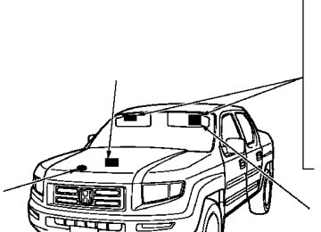
The vehicle identification number (VIN) is the 17-digit number your dealer uses to register your vehicle for warranty purposes. It is also necessary for licensing and insuring your vehicle. The easiest place to find the VIN is on a plate fastened to the top of the dashboard. You can see it by looking through the windshield on the driver’s side. It is also on the certification label attached to the driver’s doorjamb, and is stamped on the engine compartment bulkhead. The VIN is also provided in bar code on the certification label.
290
VEHICLE IDENTIFICATION NUMBER
CERTIFICATION LABEL
Main MenuTable of Contentsst 04/12/03 17:04:00 31SJC600 0296
The engine number is stamped into the engine block. It is on the front.
The transmission number is on a label on top of the transmission.
ENGINE NUMBER
Identification Numbers
AUTOMATIC TRANSMISSION NUMBER
291
Main MenuTable of Contentsst 04/12/03 17:04:18 31SJC600 0297
Specifications
Dimensions Length Width Height Wheelbase Track
Front Rear
Weights Gross vehicle weight rating
Gross combined weight * rating (GCWR) Maximum load limit (Payload)
206.7 in (5,250 mm) 78.0 in (1,980 mm) 70.3 in (1,785 mm) 122.0 in (3,100 mm) 67.1 in (1,705 mm) 66.9 in (1,700 mm)
See the tire information label attached to the driver’s doorjamb.
10,088 lbs (4,575 kg)
1,530 lbs (690 kg) 1,480 lbs (670 kg)
*
*
*
1 :
* *
2 : 3 :
The GCWR must be reduced 2 percent for every 1,000 feet (305
meters) of elevation. On vehicles without moonroof or navigation system On vehicles with moonroof and navigation systemCapacities Fuel tank
Engine coolant Engine oil
Automatic transmission fluid Rear differential fluid Transfer assembly fluid Windshield washer reservoir
Change * Total Change *
Including filter Without filter
Total Change Total
Change Total
Change Total
Approx. 22.01 US gal (83.3 ) 1.64 US gal (6.2 ) 2.14 US gal (8.1 )
4.5 US qt (4.3 )
4.2 US qt (4.0 )
5.3 US qt (5.0 ) 3.3 US qt (3.1 ) 8.6 US qt (8.1 )
2.79 US qt (2.64
3.01 US qt (2.85 )0.45 US qt (0.43 ) 0.48 US qt (0.45 )
4.8 US qt (4.5 )
Air Conditioning Refrigerant type Charge quantity Lubricant type
292
HFC-134a (R-134a) −
21.2 23.0 oz (600 650 g)
−
ND-OIL8
*
1 :
*
2 :
Including the coolant in the reserve tank and that remaining in the engine. Reserve tank capacity: 0.16 US gal (0.6 ) Excluding the oil remaining in the engine.
Main MenuTable of Contentsst 04/12/03 17:04:41 31SJC600 0298
High/Low
Lights Headlights Front turn signal/Parking/ Hazard lights Rear turn signal/hazard lights Brake/Taillights Back-up lights License plate lights High-mount brake lights Individual map lights
Front Rear
Bed lights Console compartment light Glove box light Vanity mirror light Door courtesy lights
Battery Capacity
12 V 12 V
− −
60/55 W (HB2) 28/8 W
(Amber)
12 V 12 V 12 V 12 V 12 V 12 V 12 V 12 V 12 V 12 V 12 V 12 V
− − − − − − − − − − − −
21 W 21/5 W 18 W 3 CP 3 CP 8 W 5 W 3 CP 1.4 W 3.4 W 2 W 3.8 W
12 V
−
72 AH/20 HR
Fuses Interior
Under-hood
Engine Type
Bore x Stroke Displacement Compression ratio Spark plugs
Specifications
See page 285 or the fuse label attached to the inside of the fuse box lid under the dashboard. See page 284 or the fuse box lid.
Water cooled 4-stroke SOHC VTEC,
V6 gasoline engine
3.50 x 3.66 in (89.0 x 93.0 mm)
211.8 cu-in (3,471 cm )
10.0 : 1
NGK: DENSO:
IZFR5K-11
SKJ16DR-M11Alignment Toe-in
Camber
Caster
Tires Size
Pressure
Front Rear Front Rear Front
0.00 in (0.0 mm) 0.00 in (0.0 mm)
0°50’ − 0°50’ − 1°53’
Front/Rear Spare Front/Rear Spare
P245/65R17 105S T165/90R17 105M
32 psi (220 kPa , 2.2 kgf/cm ) 60 psi (420 kPa , 4.2 kgf/cm )
293
Main MenuTable of Contentsst 04/12/03 17:04:51 31SJC600 0299
DOT Tire Quality Grading (U.S. Vehicles)
Treadwear The treadwear grade is a compara- tive rating based on the wear rate of the tire when tested under controlled conditions on a specified government test course. For example, a tire graded 150 would wear one and one- half (1 1/2) times as well on the government course as a tire graded 100. The relative performance of tires depends upon the actual condi- tions of their use, however, and may depart significantly from the norm due to variations in driving habits, service practices, and differences in road characteristics and climate.
The tires on your vehicle meet all U.S. Federal Safety Requirements. All tires are also graded for treadwear, traction, and temperature performance according to Department of Transportation (DOT) standards. The following explains these gradings.
Uniform Tire Quality Grading Quality grades can be found where applicable on the tire sidewall between the tread shoulder and the maximum section width. For example:
Treadwear 200
Traction AA Temperature AAll passenger car tires must conform to Federal Safety Requirements in addition to these grades.
294
−
AA, A, B, C
Traction The traction grades, from highest to lowest, are AA, A, B, and C. Those grades represent the tire’s ability to stop on wet pavement as measured under controlled conditions on specified government test surfaces of asphalt and concrete. A tire marked C may have poor traction performance.
Warning: The traction grade assigned to this tire is based on straight-ahead braking traction tests, and does not include acceleration, cornering, hydroplaning, or peak traction characteristics.
Main MenuTable of Contentsst 04/12/03 17:04:55 31SJC600 0300
−
A, B, C
Temperature The temperature grades are A (the highest), B, and C, representing the tire’s resistance to the generation of heat and its ability to dissipate heat when tested under controlled conditions on a specified indoor laboratory test wheel. Sustained high temperature can cause the material of the tire to degenerate and reduce tire life, and excessive temperature can lead to sudden tire failure. Grade C corresponds to a level of performance that all passenger car tires must meet under the Federal Motor Vehicle Safety Standard No. 109. Grades B and A represent higher levels of performance on the laboratory test wheel than the minimum required by law.
DOT Tire Quality Grading (U.S. Vehicles)
Warning: The temperature grade for this tire is established for a tire that is properly inflated and not overloaded. Excessive speed, underinflation, or excessive loading, either separately or in combination, can cause heat buildup and possible tire failure.
295
Main MenuTable of Contentsst 04/12/03 17:05:14 31SJC600 0301
Tire Labeling
The tires that came on your vehicle have a number of markings. Those you should be aware of are described below.
TireSize Whenever tires are replaced, they should be replaced with tires of the same size. Following is an example of tire size with an explanation of what each component means.
P245/65R17 105S
−
Vehicle type (P indicates passenger vehicle).
245
−
Tire width in millimeters.
65
−
Aspect ratio (the tire’s section height as a percentage of its width).
17
−
Rim diameter in inches.
FW6X
−
Tire type code.
2202
−
Date of manufacture.
MaximumTirePressure Max Press
−
The maximum air pressure the tire can hold.
MaximumTireLoad Max Load
−
The maximum load the tire can carry at maximum air pressure.
105
−
Load index (a numerical code associated with the maximum load the tire can carry).
−
Speed symbol (an alphabetical code indicating the maximum speed rating).
TireIdentificationNumber The tire identification number (TIN) is a group of numbers and letters that look like the following example TIN.
DOT B97R FW6X 2202
DOT
−
This indicates that the tire meets all requirements of the U.S. Department of Transportation.
−
Tire construction code (R indicates radial).
B97R
−
Manufacturer’s identification mark.
296
Main MenuTable of Contentsst 04/12/03 17:05:24 31SJC600 0302
The burning of gasoline in your vehicle’s engine produces several by- products. Some of these are carbon monoxide (CO), oxides of nitrogen (NOx), and hydrocarbons (HC). Gasoline evaporating from the tank also produces hydrocarbons. Con- trolling the production of NOx, CO, and HC is important to the environ- ment. Under certain conditions of sunlight and climate, NOx and HC react to form photochemical ‘‘smog.’’ Carbon monoxide does not contri- bute to smog creation, but it is a poisonous gas.
*
The Clean Air Act The United States Clean Air Act sets standards for automobile emissions. It also requires that automobile manufacturers explain to owners how their emissions controls work and what to do to maintain them. This section summarizes how the emissions controls work.
*
In Canada, Honda vehicles comply
with the Canadian emission requirements, as specified in an agreement with Environment Canada, at the time they are manufactured.
Crankcase Emissions Control System Your vehicle has a positive crankcase ventilation system. This keeps gasses that build up in the engine’s crankcase from going into the atmosphere. The positive crankcase ventilation valve routes them from the crankcase back to the
Emissions Controls
intake manifold. They are then drawn into the engine and burned.
Evaporative Emissions Control System As gasoline evaporates in the fuel tank, an evaporative emissions control canister filled with charcoal adsorbs the vapor. It is stored in this canister while the engine is off. After the engine is started and warmed up, the vapor is drawn into the engine and burned during driving.
Onboard Refueling Vapor Recovery The onboard refueling vapor recovery (ORVR) system captures the fuel vapors during refueling. The vapors are adsorbed in a canister filled with activated carbon. While driving, the fuel vapors are drawn into the engine and burned off.
297
Main MenuTable of Contentsst 04/12/03 17:05:35 31SJC600 0303
Emissions Controls
Exhaust Emissions Controls The exhaust emissions controls include four systems: PGM-FI, ignition timing control, exhaust gas recirculation, and three way catalytic converter. These four systems work together to control the engine’s combustion and minimize the amount of HC, CO, and NOx that comes out the tailpipe. The exhaust emissions control systems are separate from the crankcase and evaporative emissions control systems.
PGM-FISystem The PGM-FI system uses sequential multiport fuel injection. It has three subsystems: air intake, engine control, and fuel control. The powertrain control module (PCM) uses various sensors to determine how much air is going into the engine. It then controls how much fuel to inject under all operating conditions.
298
IgnitionTimingControlSystem This system constantly adjusts the ignition timing, reducing the amount of HC, CO, and NOx produced.
ExhaustGasRecirculation(EGR) System The exhaust gas recirculation (EGR) system takes some of the exhaust gas and routes it back into the intake manifold. Adding exhaust gas to the air/fuel mixture reduces the amount of NOx produced when the fuel is burned.
ThreeWayCatalyticConverter The three way catalytic converter is in the exhaust system. Through chemical reactions, it converts HC, CO, and NOx in the engine’s exhaust to carbon dioxide (CO ), nitrogen (N ), and water vapor.
Replacement Parts The emissions control systems are designed and certified to work to- gether in reducing emissions to levels that comply with the Clean Air Act. To make sure the emissions remain low, you should use only new Honda replacement parts or their equivalent for repairs. Using lower quality parts may increase the emissions from your vehicle.
The emissions control systems are covered by warranties separate from the rest of your vehicle. Read your warranty manual for more informa- tion.
Main MenuTable of Contentsst 04/12/03 17:05:43 31SJC600 0304
Three Way Catalytic Converter
The three way catalytic converter contains precious metals that serve as catalysts, promoting chemical reactions to convert the exhaust gasses without affecting the metals. The catalytic converter is referred to as a three-way catalyst, since it acts on HC, CO, and NOx. A replacement unit must be an original Honda part or its equivalent.
The three way catalytic converter must operate at a high temperature for the chemical reactions to take place. It can set on fire any combustible materials that come near it. Park your vehicle away from high grass, dry leaves, or other flammables.
THREE WAY CATALYTIC CONVERTER A defective three way catalytic converter contributes to air pollution, and can impair your engine’s per- formance. Follow these guidelines to protect your vehicle’s three way catalytic converter.
Always use unleaded gasoline. Even a small amount of leaded gasoline can contaminate the catalyst metals, making the three way catalytic converter ineffective.
WARM UP THREE WAY CATALYTIC CONVERTER
Keep the engine tuned-up.
Have your vehicle diagnosed and repaired if it is misfiring, back- firing, stalling, or otherwise not running properly.
299
Main MenuTable of Contentsst 04/12/03 17:05:56 31SJC600 0305
State Emissions Testing
Testing of Readiness Codes If you take your vehicle for a state emissions test shortly after the battery has been disconnected or gone dead, it may not pass the test. This is because of certain ‘‘readiness codes’’ that must be set in the on- board diagnostics for the emissions systems. These codes are erased when the battery is disconnected, and set again only after several days of driving under a variety of conditions.
If the testing facility determines that the readiness codes are not set, you will be requested to return at a later date to complete the test. If you must get the vehicle retested within the next two or three days, you can condition the vehicle for retesting by doing the following.
Make sure the gas tank is nearly, but not completely full (around 3/4).
300
Make sure the vehicle has been parked with the engine off for 6
hours or more.Make sure the ambient temperature is between 40° and 95°F.
Without touching the accelerator pedal, start the engine, and let it idle for 20 seconds.
Keep the vehicle in Park. Increase the engine speed to 2,000 rpm, and hold it there until the temperature gauge rises to at least 1/4 of the scale (about 3 minutes).
Select a nearby lightly traveled major highway where you can maintain a speed of 50 to 60 mph (80 to 97 km/h) for at least 20
minutes. Drive on the highway in D. Do not use the cruise control. When traffic allows, drive for 90
seconds without moving theaccelerator pedal. (Vehicle speed may vary slightly; this is okay.) If you cannot do this for a continuous 90 seconds because of traffic conditions, drive for at least 30 seconds, then repeat it two more times (for a total of 90
seconds).Then drive in city/suburban traffic for at least 10 minutes. When traffic conditions allow, let the vehicle coast for several seconds without using the accelerator pedal or the brake pedal.
Stop the vehicle, turn off the ignition switch, and leave it off for 30 minutes.
If the testing facility determines the readiness codes are still not set, see your dealer.
Main MenuTable of Contentsst 04/12/03 17:06:00 31SJC600 0306
Warranty and Customer Relations
Customer Service
Information
Warranty Coverages Reporting Safety Defects
................................ ....................
. 302
. 303(U.S. Vehicles)
Authorized Manuals
.......................... .....................
. 304
. 305301
Main Menust 04/12/03 17:06:10 31SJC600 0307
Customer Service Information
Canadian Owners: CUSTOMER RELATIONS RELATIONS AVEC LA CLIENTÉLE Honda Canada Inc. 715 Milner Avenue Toronto, ON M1B 2K8
Tel: 1-888-9-HONDA-9
Fax: Toll-free 1-877-939-0909
Toronto (416) 287-4776In Puerto Rico and the U.S. Virgin Islands:
Bella International P.O. Box 190816
San Juan, PR 00919-0816Tel: (787) 620-7098
Honda dealership personnel are trained professionals. They should be able to answer all your questions. If you encounter a problem that your dealership does not solve to your satisfaction, please discuss it with the dealership’s management. The service manager or general manager can help. Almost all problems are solved in this way.
If you are dissatisfied with the decision made by the dealership’s management, contact your Honda Customer Service Office.
U.S. Owners: American Honda Motor Co., Inc. Automobile Customer Service Mail Stop 500-2N-7A 1919 Torrance Boulevard Torrance, California 90501-2746