- 2012 Honda Civic Hybrid Owners Manuals
- Honda Civic Hybrid Owners Manuals
- 2008 Honda Civic Hybrid Owners Manuals
- Honda Civic Hybrid Owners Manuals
- 2010 Honda Civic Hybrid Owners Manuals
- Honda Civic Hybrid Owners Manuals
- 2013 Honda Civic Hybrid Owners Manuals
- Honda Civic Hybrid Owners Manuals
- 2006 Honda Civic Hybrid Owners Manuals
- Honda Civic Hybrid Owners Manuals
- 2007 Honda Civic Hybrid Owners Manuals
- Honda Civic Hybrid Owners Manuals
- 2011 Honda Civic Hybrid Owners Manuals
- Honda Civic Hybrid Owners Manuals
- 2009 Honda Civic Hybrid Owners Manuals
- Honda Civic Hybrid Owners Manuals
- 2005 Honda Civic Hybrid Owners Manuals
- Honda Civic Hybrid Owners Manuals
- 2004 Honda Civic Hybrid Owners Manuals
- Honda Civic Hybrid Owners Manuals
- 2003 Honda Civic Hybrid Owners Manuals
- Honda Civic Hybrid Owners Manuals
- Download PDF Manual
-
Charging System Indicator Malfunction Indicator Lamp Brake System Indicator Fuses Fuse Locations Emergency Towing
...................... .................... ............. ................................ .............. ......... .......... ....... ............... .............................................. .............................. ......................
. 176
. 177
. 182
. 184
. 186
. 188
. 189
. 190
. 191
. 192
. 195
. 197175
Main Menust 04/07/20 13:18:47 31S5B630 0179
Compact Spare Tire
Use the compact spare tire as a temporary replacement only. Get your regular tire repaired or replaced, and put it back on your vehicle as soon as you can.
Check the inflation pressure of the compact spare tire every time you check the other tires. It should be inflated to: 60 psi (420 kPa , 4.2 kgf/cm )
176
Follow these precautions:
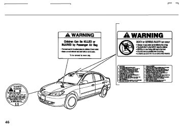
INDICATOR LOCATION MARK
Never exceed 50 mph (80 km/h).
This tire gives a harsher ride and less traction on some road sur- faces. Use greater caution while driving.
Do not mount snow chains on the compact spare tire.
Do not use your compact spare tire on another vehicle unless it is the same make and model.
TREAD WEAR INDICATOR BAR
Replace the tire when you can see the tread wear indicator bars. The replacement should be the same size and design tire, mounted on the same wheel. The spare tire is not designed to be mounted on a regular wheel, and the spare wheel is not designed for mounting a regular tire.
Main MenuTable of Contentsst 04/07/20 13:18:56 31S5B630 0180
If you have a flat tire while driving, stop in a safe place to change it. Drive slowly along the shoulder until you get to an exit or an area that is far away from the traffic lanes.
The vehicle can easily roll off the jack, seriously injuring anyone underneath.
Follow the directions for changing a tire exactly, and never get under the vehicle when it is supported only by the jack.
1.
2.
Park the vehicle on firm, level and non-slippery ground. Put the transmission in Park (CVT) or Reverse (manual). Apply the parking brake.
Turn on the hazard warning lights, and turn the ignition switch to LOCK (0). Have all the passengers get out of the vehicle while you change the tire.
Changing a Flat Tire
SPARE TIRE
TRUNK FLOOR
TOOL KIT JACK Open the trunk. Raise the trunk 3. floor mat and the trunk floor by lifting up on the back edge.
4.
Take the tool kit out of the trunk.
5.
Unscrew the wing bolt and take the spare tire out of its well.
CONTINUED
177
Main MenuTable of Contentsst 04/07/20 13:19:03 31S5B630 0181
Changing a Flat Tire
JACK
JACKING POINTS
6.
Turn the jack’s end counterclockwise to loosen it, then remove the jack.
WHEEL NUT WRENCH
7.
Loosen each wheel nut 1/2 turn with the wheel nut wrench.
8.
Place the jack under the jacking point nearest the tire you need to change. Turn the end bracket clockwise until the top of the jack contacts the jacking point. Make sure the jacking point tab is resting in the jack notch.
178
Main MenuTable of Contentsst 04/07/20 13:19:11 31S5B630 0182
Changing a Flat Tire
WHEEL NUT WRENCH 9.
EXTENSION Use the extension and the wheel nut wrench as shown to raise the vehicle until the flat tire is off the ground.
BRAKE HUB
10.
Remove the wheel nuts, then remove the flat tire. Handle the wheel nuts carefully; they may be hot from driving. Place the flat tire on the ground with the outside surface facing up.
11.
Before mounting the spare tire, wipe any dirt off the mounting surface of the wheel and hub with a clean cloth. Wipe the hub carefully; it may be hot from driving.
CONTINUED
179
Main MenuTable of Contentsst 04/07/20 13:19:21 31S5B630 0183
Changing a Flat Tire
WING BOLT
SPACER CONE
12.
Put on the spare tire. Put the wheel nuts back on finger-tight, then tighten them in a crisscross pattern with the wheel nut wrench until the wheel is firmly against the hub. Do not try to tighten them fully.
14.
Tighten the wheel nuts securely in the same crisscross pattern. Have the wheel nut torque checked at the nearest automotive service facility. Tighten the wheel nuts to: 80 lbf·ft (108 N·m , 11 kgf·m)
13.
Lower the vehicle to the ground and remove the jack.
15.
Remove the center cap before storing the flat tire in the trunk well.
16.
Place the flat tire face down in the spare tire well.
17.
Remove the spacer cone from the wing bolt, turn it over, and put it back on the bolt.
18.
Secure the flat tire by screwing the wing bolt back into its hole.
180
Main MenuTable of Contentsst 04/07/20 13:19:26 31S5B630 0184
Changing a Flat Tire
19.
Store the jack in the trunk with the end bracket on the left side. Turn the jack’s end bracket to lock it in place. Store the tool kit.
Loose items can fly around the interior in a crash and could seriously injure the occupants.
Store the wheel, jack, and tools securely before driving.
20.
Store the center cap in the trunk. Make sure it does not get scratched or damaged.
21.
Lower the trunk floor and trunk floor mat, then close the trunk lid.
181
Main MenuTable of Contentsst 04/07/20 13:19:36 31S5B630 0185
If the Engine Won’t Start
Diagnosing why the engine won’t start falls into two areas, depending on what you hear when you turn the key to START (III):
You hear nothing, or almost nothing. The engine’s starter motor does not operate at all, or operates very slowly.
You can hear the starter motor operating normally, or the starter motor sounds like it is spinning faster than normal, but the engine does not start up and run.
Nothing Happens or the Starter Motor Operates Very Slowly When you turn the ignition switch to START (III), you do not hear the normal noise of the engine trying to start. You may hear a clicking sound or series of clicks, or nothing at all. Check these things:
Check the transmission interlock. If you have a manual transmission, the clutch pedal must be pushed all the way to the floor or the starter will not operate. With an automatic transmission, it must be in Park or Neutral.
Turn the ignition switch to ON (II). Turn on the headlights, and check their brightness. If the headlights areverydimordonotcomeonat all, the battery is discharged. See Jump Starting
on page
184
182
Turn the ignition switch to START (III). If the headlights do not dim, check the condition of the fuses. If thefusesareOK,thereis probably something wrong with the electrical circuit for the ignition switch or starter motor. You will need a qualified technician to determine the Emergency Towing problem (see ). on page 197
If the headlights dim noticeably or go out when you try to start the engine, either the battery is discharged or the connections are corroded. Check the condition of the 12 volt battery and terminal connections (see page 173). You canthentryjumpstartingthe vehicle from a booster battery (see page
184
).
Main MenuTable of Contentsst 04/07/20 13:19:45 31S5B630 0186
The Starter Operates Normally In this case, the starter motor’s speed sounds normal, or even faster than normal, when you turn the ignition switch to START (III), but the engine does not run.
Are you using a properly coded key? An improperly coded key will cause the immobilizer system indicator in the instrument panel to blink rapidly (see page ).
71
Are you using the proper starting Starting the procedure? Refer to Engine 127
on page
Do you have fuel? Check the fuel gauge; the low fuel indicator may not be working.
There may be an electrical problem, such as no power to the fuel pump. Check all the fuses (see page
192
).
If the Engine Won’t Start
Ifyoufindnothingwrong,youwill need a qualified technician to find the problem. See Towing on page
Emergency 197.
183
Main MenuTable of Contentsst 04/07/20 13:19:56 31S5B630 0187
Jump Starting
Although this seems like a simple procedure, you should take several precautions.
A battery can explode if you do not follow the correct procedure, seriously injuring anyone nearby.
Keep all sparks, open flames, and smoking materials away from the battery.
You cannot start your vehicle with an automatic transmission (CVT) by pushing or pulling it.
184
To jump start your vehicle:
1.
Open the hood, and check the physical condition of the 12 volt battery. In very cold weather, check the condition of the electrolyte. If it seems slushy or like ice, do not try jump starting until it thaws.
If a battery sits in extreme cold, the electrolyte inside can f reeze. Attempting to jump start with a f rozen battery can cause it to rupture.
BOOSTER BATTERY
The numbers in the illustration show you the order to connect the jumper cables.
2.
Turn off all the electrical acces- sories: heater, A/C, stereo system, lights, etc. Put the transmission in Neutral or Park, and set the parking brake.
3.
+
) terminal on your
Connect one jumper cable to the positive ( battery. Connect the other end to the positive ( ) terminal on the + booster battery.
Main MenuTable of Contentsst 04/07/20 13:20:04 31S5B630 0188
6.
7.
Start the vehicle. If the starter motor still operates slowly, check that the jumper cables have good metal-to-metal contact.
Once your vehicle is running, disconnect the negative cable from your vehicle, then from the booster battery. Disconnect the positive cable from your vehicle, then from the booster battery.
Keep the ends of the jumper cables away from each other and any metal on the vehicle until everything is disconnected. Otherwise, you may cause an electrical short.
4.
−
Connect the second jumper cable to the negative ( ) terminal on the booster battery. Connect the other end to the metal projection as shown. Do not connect this jumper cable to any other part of the engine.
5.
If the booster battery is in another vehicle, have an assistant start that vehicle and run it at a fast idle.
Jump Starting
If your vehicle’s 12 volt battery is disconnected or goes dead, the IMA battery level gauge reading will not be correct the next time you turn the ignition switch to ON (II). It will show less than the actual level temporarily. It will show the correct level after you drive for at least 30
minutes.185
Main MenuTable of Contentsst 04/07/20 13:20:13 31S5B630 0189
If the Engine Overheats
The reading on the vehicle’s temperature gauge should stay in the midrange. If it climbs to the red mark, you should determine the reason (hot day, driving up a steep hill, etc.).
If the vehicle overheats, you should take immediate action. The only indicationmaybethetemperature gauge climbing to or above the red mark. Or you may see steam or spray coming from under the hood.
Driving with the temperature gauge reading at the red mark can cause serious damage to the engine.
186
Steam and spray from an overheated engine can seriously scald you.
Do not open the hood if steam is coming out.
1.
2.
Safely pull to the side of the road. Put the transmission in Neutral or Park, and set the parking brake. Turn off all accessories, and turn on the hazard warning lights.
If you see steam and/or spray coming from under the hood, turn off the engine. Wait until you see no more signs of steam or spray, then open the hood.
3.
If you do not see steam or spray, leave the engine running, and watch the temperature gauge. If the high heat is due to overloading, the engine should start to cool down almost immediately. If it does, wait until the temperature gauge comes down to the midpoint, then continue driving.
4.
If the temperature gauge stays at the red mark, turn off the engine.
5.
Look for any obvious coolant leaks, such as a split radiator hose. Everything is still extremely hot, so use caution. If you find a leak, it must be repaired before you Emergency continue driving (see Towing ). 197
on page
Main MenuTable of Contentsst 04/07/20 13:20:22 31S5B630 0190
If the Engine Overheats
6.
7.
If you do not find an obvious leak, check the coolant level in the radiator reserve tank. Add coolant if the level is below the MIN mark.
If there was no coolant in the reserve tank, you may need to add coolant to the radiator. Let the engine cool down until the reading reaches the middle of the temperature gauge or lower, before checking the radiator.
Removing the radiator cap while the engine is hot can cause the coolant to spray out, seriously scalding you.
Always let the engine and radiator cool down before removing the radiator cap.
8.
9.
Using gloves or a large heavy cloth, turn the radiator cap counterclockwise, without pushing down, to the first stop. After the pressure releases, push down on the cap, and turn it until it comes off.
Start the engine, and set the temperature control dial to maximum heat. Add coolant to the radiator up to the base of the filler neck. If you do not have the proper coolant mixture available, you can add plain water. Remember to have the cooling system drained and refilled with the proper mixture as soon as you can.
10.
Put the radiator cap back on tightly. Run the engine, and watch the temperature gauge. If it goes back to the red mark, the engine needs repair (see Towing on page
Emergency 197
).
11.
If the temperature stays normal, check the coolant level in the radiator reserve tank. If it has gone down, add coolant to the MAX mark. Put the cap back on tightly.
187
Main MenuTable of Contentsst 04/07/20 13:20:30 31S5B630 0191
Low Oil Pressure Indicator
This indicator should never come on when the engine is running. If it starts flashing
or stays on, the oil pressure has dropped very low or lost pressure. Serious engine damage is possible and you should take immediate action.
Running the engine with low oil pressure can cause serious mechanical damage almost immediately. Turn of f the engine as soon as you can saf ely get the vehicle stopped.
1.
2.
3.
4.
188
Safely pull off the road, and shut off the engine. Turn on the hazard warning indicators.
Let the vehicle sit for a minute. Open the hood, and check the oil level (see page ). An engine very low on oil can lose pressure during cornering and other driving maneuvers.
116
The engine running generates the oil pressure. When the Auto Idle Stop is activated, the engine is stopped, the oil pressure is dropped, and the low oil pressure indicator does not come on.
If necessary, add oil to bring the level back to the full mark on the dipstick (see page
150
).
Start the engine, and watch the oil pressure indicator. If it does not go out within 10 seconds, turn off the engine. There is a mechanical problem that needs to be repaired before you can continue driving (see 197
Emergency Towing ).
on page
Main MenuTable of Contentsst 04/07/20 13:20:37 31S5B630 0192
Charging System Indicator
If the charging system indicator comes on brightly when the engine is running,
the 12 volt battery is not being charged.
Immediately turn off all electrical accessories. Try not to use other electrically operated controls such as the power windows and rear window defogger. Keep the engine running; starting the engine will discharge the battery rapidly.
Go to a service station or garage where you can get technical assistance.
If the Auto Idle Stop is active for an extended period, the charging system indicator may come on. If it happens, start the engine.
The charging system indicator may also come on if the Integrated Motor Assist (IMA) battery charge drops below a desired level and the engine starts to recharge the battery.
This indicator may blink after you start the vehicle in the morning when the temperature is below 20
− °F ( 30°C). It will stop blinking when the IMA battery warms up.−
189
Main MenuTable of Contentsst 04/07/20 13:20:46 31S5B630 0193
Malfunction Indicator Lamp
If the indicator comes on while driving, it means one of the engine’s emissions
control systems may have a problem. Even though you may feel no difference in your vehicle’s performance, it can reduce your fuel economy and cause increased emissions. Continued operation may cause serious damage.
If you have recently refueled your vehicle, the indicator coming on could be due to a loose or missing fuel fill cap. Tighten the cap until it clicks at least three times. Tightening the cap will not turn the indicator off immediately; it takes at least three days of normal driving.
190
If the indicator comes on repeatedly, even though it may turn off as you continue driving, have the vehicle checked by the dealer as soon as possible.
If your vehicle battery has been disconnected or gone dead, these codes are erased. It takes at least three days of driving under various conditions to set the codes again.
To check if they are set, turn the ignition switch to ON (II), without starting the engine. The Malfunction Indicator Lamp will come on for 20
seconds.Ifitthengoesoff,the readiness codes are set. If it blinks 5
times, the readiness codes are not set. If possible, do not take your vehicle for a state emissions test until the readiness codes are set. Refer to State Emissions Testing for more information (see page210
).
If you keep driving with the Malf unction Indicator Lamp on, you can damage your vehicle’s emissions controls and the engine. Those repairs may not be covered by your vehicle’s warranties.
This indicator may also come on along with the ‘‘D’’ indicator.
Readiness Code Your vehicle has certain ‘‘readiness codes’’ that are part of the on-board diagnostics for the emissions systems. In some states, part of the emissions testing is to make sure these codes are set. If they are not set, the test cannot be completed.
Main MenuTable of Contentsst 04/07/20 13:20:54 31S5B630 0194
U.S.
Canada
The brake system indicator normally comes on when you turn the ignition switch to ON (II), and as a reminder to check the parking brake. It will stay on if you do not fully release the parking brake.
If the brake system indicator comes on while driving, the brake fluid level is probably low. Press lightly on the brake pedal to see if it feels normal. If it does, check the brake fluid level thenexttimeyoustopataservice station (see page
158
).
If the fluid level is low, take your vehicle to a dealer, and have the brake system inspected for leaks or worn brake pads.
However, if the brake pedal does not feel normal, you should take immediate action. A problem in one
Brake System Indicator
If the ABS indicator comes on with the brake system indicator, have your vehicle inspected by your dealer immediately.
part of the system’s dual circuit design will still give you braking at two wheels. You will feel the brake pedal go down much farther before the vehicle begins to slow down, and you will have to press harder on the pedal.
Slow down by shifting to a lower gear, and pull to the side of the road when it is safe. Because of the long distance needed to stop, it is hazardous to drive the vehicle. You should have it towed and repaired as soon as possible (see Towing 197).
Emergency
on page
If you must drive the vehicle a short distance in this condition, drive slowly and carefully.
191
Main MenuTable of Contentsst 04/07/20 13:21:03 31S5B630 0195
Fuses
INTERIOR
UNDER-HOOD (PRIMARY)
UNDER-HOOD (SECONDARY)
TAB
TAB
The vehicle’s fuses are contained in three fuse boxes.
The interior fuse box is underneath the steering column. To open it, turn the knobs as shown.
The primary and secondary under- hood fuse boxes are in the engine compartment on the driver’s side.
192
Main MenuTable of Contentsst 04/07/20 13:21:13 31S5B630 0196
195
and
Checking and Replacing Fuses If something electrical in your vehicle stops working, check for a blown fuse first. Determine from the chart on pages , or the diagram on the fuse box lid, which fuse or fuses control that device. Check those fuses first, but check all the fuses before deciding that a blown fuse is the cause. Replace any blown fuses, and check if the device work.
196
FUSE
BLOWN
Fuses
BLOWN
1.
Turn the ignition switch to LOCK (0). Make sure the headlights and all other accessories are off.
2.
Remove the cover from the fuse box.
3.
Check each of the large fuses in the primary under-hood fuse box by looking through the top at the wire inside. Removing these fuses requires a Phillips-head screwdriver.
4.
Check the smaller fuses in the under-hood fuse boxes and all the fuses in the interior fuse box by pulling out each one with the fuse puller provided in the primary under-hood fuse box.
5.
Look for a burned wire inside the fuse. If it is burned, replace it with one of the spare fuses of the same rating or lower.
CONTINUED
193
Main MenuTable of Contentsst 04/07/20 13:21:20 31S5B630 0197
Fuses
If you cannot drive the vehicle without fixing the problem, and you do not have a spare fuse, take a fuse of the same rating or a lower rating from one of the other circuits. Make sureyoucandowithoutthatcircuit temporarily (such as the accessory power socket or radio).
If you replace the blown fuse with a spare fuse that has a lower rating, it might blow out again. This does not indicate anything wrong. Replace the fuse with one of the correct rating as soon as you can.
6.
If the replacement fuse of the same rating blows in a short time, there is probably a serious electrical problem in your vehicle. Leave the blown fuse in that circuit and have your vehicle checked by a qualified mechanic.
If the radio fuse is removed, the audio system will disable itself. The next time you turn on the radio you will see ‘‘COdE’’ in the frequency display. Use the preset buttons to enter the five-digit code (see page 106
).
When the audio system is disabled, the clock setting in the audio system will be canceled. You will need to reset the clock according to the instructions in the audio system sectiononthisowner’smanual.
Replacing a f use with one that has a higher rating greatly increases the chances of damaging the electrical system. If you do not have a replacement f use with the proper rating f or the circuit, install one with a lower rating.
194
Main MenuTable of Contentsst 04/07/20 13:21:28 31S5B630 0198
PRIMARY UNDER-HOOD FUSE BOX
SECONDARY UNDER-HOOD FUSE BOX
No. Amps. 20 A
Circuits Protected
Cooling Fan
No. Amps. 20 A 10 A 10 A 20 A 10 A 15 A 15 A 20 A 10 A 40 A 10
30 A 11
40 A 12
40 A 13
40 A 14
20 A 15
20 A 16
20 A 17
60 A 18
80 A 19
50 A 20
− −25 7.5A 30A
21
Circuits Protected
Condenser Fan IMA Small Light Cooling Fan Hazard FI ECU Horn, Stop ABS F/S Back Up ABS Motor Rear Defroster Heater Motor Power Window Option Left Headlight Door Lock Right Headlight EPS Battery Ignition 1
Spare FusesFuse Locations
195
Main MenuTable of Contentsst 04/07/20 13:21:35 31S5B630 0199
Fuse Locations
INTERIOR FUSE BOX
Circuits Protected
Ignition Coil IN LAF Heater (Daytime running lights ) FI-ECU Not Used
*
No. Amps. 15 A 20 A (10 A) 10 A −
196
No. Amps. 7.5 A − 7.5 A 15 A 7.5 A 10
7.5 A 11
(7.5 A) 12
10 A 13
10 A 14
(10 A) 15
7.5 A 16
15 A 17
15 A 18
7.5 A 19
20 A 20
7.5 A 21
20 A 22
20 A 23
20 A 24
20 A 25
7.5 A 26Circuits Protected
*
*
Power Window Relay Not Used Accessory, Radio Ignition Coil EX Meter ABS (Daytime running lights ) SRS Remote Control Mirrors (SCTY ) IMA Fuel Pump Accessory Power Socket Turn Signal Lights Front Wiper STS (Steering Switch) Front Right Power Window Front Left Power Window Rear Left Power Window Rear Right Power Window Cooling Fan Relay
* *
1 : On Canadian models 2 : Optional Security System
Main MenuTable of Contentsst 04/07/20 13:21:51 31S5B630 0200
If your vehicle needs to be towed, call a professional towing service or organization. Never tow your vehicle with just a rope or chain. It is very dangerous. There are two ways to tow your vehicle.
−
Flat-bedEquipment loads your vehicle on the back of a truck. port your vehicle.
This is the best way to trans-
The operator
−
The tow
Wheel-liftEquipment truck uses two pivoting arms that go under the tires (front or rear) and lift them off the ground. The other two This is tires remain on the ground. an acceptable way to tow your vehicle.
If, due to damage, your vehicle must be towed with the front wheels on the ground, do the following:
ManualTransmission:
Release the parking brake. Shift the transmission to Neutral.
AutomaticTransmission(CVT): Release the parking brake. Start the engine. Shift to D, then to N. Turn off the engine.
Improper towing preparation will damage the transmission. Follow the above procedure exactly. If you cannot shif t the transmission or start the engine (automatic transmission), your vehicle must be transported with the f ront wheels of f the ground.
Emergency Towing
With the front wheels on the ground, it is best to tow the vehicle no farther than 50 miles (80 km), and keep the speed below 35 mph (55 km/h).
If your vehicle is equipped with a front spoiler, remove it before towing so it is not damaged.
Trying to lif t or tow your vehicle by the bumpers will cause serious damage. The bumpers are not designed to support the vehicle’s weight.
CONTINUED
197
Main MenuTable of Contentsst 04/07/20 13:21:55 31S5B630 0201
Emergency Towing
If you decide to tow your vehicle with all four wheels on the ground, make sure you use a properly- designed and attached tow bar. Prepare the vehicle for towing as described above, and leave the ignition switch in Accessory (I) so the steering wheel does not lock. Make sure the radio and any items plugged into the accessory power socket are turned off so they do not run down the battery.
The steering system can be damaged if the steering wheel is locked. Leave the ignition switch in Accessory (I), and make sure the steering wheel turns f reely bef ore you begin towing.
198
Main MenuTable of Contentsst 04/07/20 13:21:59 31S5B630 0202
Technical Information
The diagrams in this section give you the dimensions and capacities of your vehicle, and the locations of the identification numbers. It also includes information you should know about your vehicle’s tires and emissions control systems.
Identification Numbers Specifications DOT Tire Quality Grading
................ ................................
. 200
. 202(U.S. Vehicles)
......................
. 204
Uniform Tire Quality
Grading Treadwear Traction Temperature
.................................. ................................. ...................................... ............................. .................................
Tire Labeling
. 204
. 204
. 204
. 205
. 206Emissions Controls ....................... The Clean Air Act ..................... Crankcase Emissions Control .................................... Evaporative Emissions Control ....................................
System
System
Onboard Refueling Vapor
. 207
. 207. 207
. 207
Recovery
. 207
Exhaust Emissions Controls . 208
. 208................................ ... ....................
PGM-FI System Ignition Timing Control
System
................................ Exhaust Gas Recirculation ...................
(EGR) System
Three Way Catalytic
. 208
. 208
Converter
Replacement Parts
. 208
........................... .................... . 208
.. Three Way Catalytic Converter . 209
. 210
State Emissions Testing ..............199
Main Menust 04/07/20 13:22:05 31S5B630 0203
Identification Numbers
Your vehicle has several identifying numbers in various places.
The Vehicle Identification Number (VIN) is the 17-digit number your dealer uses to register your vehicle for warranty purposes. It is also necessary for licensing and insuring your vehicle. The easiest place to find the VIN is on a plate fastened to the top of the dashboard. You can see it by looking through the windshield on the driver’s side. It is also on the Certification label attached to the driver’s doorjamb, and is stamped on the engine compartment bulkhead. The VIN is also provided in bar code on the Certification label.
200
VEHICLE IDENTIFICATION NUMBER
CERTIFICATION LABEL
Main MenuTable of Contentsst 04/07/20 13:22:10 31S5B630 0204
The Engine Number is stamped into the engine block.
The Transmission Number is on a label on top of the transmission.
The IMA Motor Number is stamped on the motor housing.
Identification Numbers
ENGINE NUMBER
TRANSMISSION NUMBER
IMA MOTOR NUMBER
201
Main MenuTable of Contentsst 04/07/20 13:22:29 31S5B630 0205
Specifications
Dimensions Length Width Height Wheelbase Track
Front Rear
Weights Gross vehicle weight rating
Engine Type
Bore x Stroke Displacement Compression ratio Spark plugs
202
174.8 in (4,440 mm) 67.5 in (1,715 mm) 56.3 in (1,430 mm) 103.1 in (2,620 mm) 57.9 in (1,470 mm) 57.9 in (1,470 mm)
Capacities Fuel tank
Engine coolant
See the certification label attached to the driver’s doorjamb.
Engine oil
Water cooled 4-stroke SOHC VTEC
4-cylinder gasoline engine
2.87 x 3.15 in (73.0 x 80.0 mm)
82 cu-in (1.339 cm )
10.8
IFR5G-11K SK16PR-L11
(NGK)
(DENSO)
Manual trans- mission fluid Automatic transmission fluid (CVT) Windshield washer reservoir
ULEV AT-PZEV
Change * Manual CVT Total
Manual CVT
Change *
Including filter Without filter
Total Change Total Change Total
Approx. 13.2 US gal (50 ) 11.9 US gal (45 )
1.08 US gal (4.1 ) 1.06 US gal (4.0 )
1.37 US gal (5.2 ) 1.35 US gal (5.1 )
3.4 US qt (3.2 ) 3.2 US qt (3.0 ) 4.0 US qt (3.8 ) 1.6 US qt (1.5 ) 1.7 US qt (1.6 ) 3.4 US qt (3.2 ) 5.7 US qt (5.4 )
U.S. Vehicles Canada Vehicles
2.6 US qt (2.5 ) 4.8 US qt (4.5 )
*
1 :
*
2 :
Including the coolant in the reserve tank and that remaining in the engine. Reserve tank capacity: Excluding the oil remaining in the engine.
0.11 US gal (0.4 )
Main MenuTable of Contentsst 04/07/20 13:22:52 31S5B630 0206
Air Conditioning Refrigerant type Charge quantity Lubricant oil type
Lights Headlights
High Low
Front Parking/Front turn signal/side marker lights Rear turn signal lights Brake/Taillights/Rear side marker lights Back-up lights Taillights High-mount brake light License plate lights Ceiling light Spotlights Trunk light
12 Volt Battery Capacity
HFC-134a (R-134a) −
17.6 19.4 oz (500 550 g)
−
SP-10
12 V 12 V 12 V
− − −
(HB3) (HB4)
60 W 51 W 24/2.2 CP
12 V 12 V
− −
21 W 21/5 W
12 V 12 V 12 V 12 V 12 V 12 V 12 V
− − − − − − −
21 W 3 CP 21 W 3 CP 8 W 8 W 5 W
12 V
−
35 AH/20 HR
Fuses Interior
Under-hood
Alignment Toe-in
Camber
Caster
Tires Size
Pressure
Front Rear Front Rear Front
Front/Rear Spare
Front/Rear Spare
* *
1 : Without ABS 2 : With ABS
Specifications
See page 196 or the fuse label attached to the inside of the fuse box door under the steering column. See page 195 or the fuse box cover.
0.00 in (0.0 mm) 0.08 in (2.0 mm)
−
0°12’ 1° − 2°20’
P185/70R14 87S T115/70D14 88M * T125/70D15 95M *
30 psi (210 kPa , 2.1 kgf/cm ) 60 psi (420 kPa , 4.2 kgf/cm )
203
Main MenuTable of Contentsst 04/07/20 13:23:02 31S5B630 0207
DOT Tire Quality Grading (U.S. Vehicles)
Treadwear The treadwear grade is a compara- tive rating based on the wear rate of the tire when tested under controlled conditions on a specified government test course. For example, a tire graded 150 would wear one and one- half (1 1/2) times as well on the government course as a tire graded 100. The relative performance of tires depends upon the actual condi- tions of their use, however, and may depart significantly from the norm due to variations in driving habits, service practices, and differences in road characteristics and climate.
The tires on your vehicle meet all U.S. Federal Safety Requirements. All tires are also graded for treadwear, traction, and temperature performance according to Department of Transportation (DOT) standards. The following explains these gradings.
Uniform Tire Quality Grading Quality grades can be found where applicable on the tire sidewall between the tread shoulder and the maximum section width. For example:
Treadwear 200
Traction AA Temperature AAll passenger car tires must conform to Federal Safety Requirements in addition to these grades.
204
−
AA, A, B, C
Traction The traction grades, from highest to lowest, are AA, A, B, and C. Those grades represent the tire’s ability to stop on wet pavement as measured under controlled conditions on specified government test surfaces of asphalt and concrete. A tire marked C may have poor traction performance.
Warning: The traction grade assigned to this tire is based on straight-ahead braking traction tests, and does not include acceleration, cornering, hydroplaning, or peak traction characteristics.
Main MenuTable of Contentsst 04/07/20 13:23:07 31S5B630 0208
DOT Tire Quality Grading (U.S. Vehicles)
−
A, B, C
Temperature The temperature grades are A (the highest), B, and C, representing the tire’s resistance to the generation of heat and its ability to dissipate heat when tested under controlled conditions on a specified indoor laboratory test wheel. Sustained high temperature can cause the material of the tire to degenerate and reduce tire life, and excessive temperature can lead to sudden tire failure. The grade C corresponds to a level of performance which all passenger car tires must meet under the Federal Motor Vehicle Safety Standard No. 109. Grades B and A represent higher levels of performance on the laboratory test wheel than the minimum required by law.
Warning: The temperature grade for this tire is established for a tire that is properly inflated and not over- loaded. Excessive speed, underinfla- tion, or excessive loading, either separately or in combination, can cause heat buildup and possible tire failure.
205
Main MenuTable of Contentsst Rim diameter in inches.
FW6X
−
Tire type code.
2202
−
Date of manufacture.
MaximumTirePressure Max Press pressure the tire can hold.
The maximum air
−
MaximumTireLoad Max Load tire can carry at maximum air pressure.
−
The maximum load the
04/07/20 13:23:25 31S5B630 0209
Tire Labeling
The tires that came on your vehicle have a number of markings. Those you should be aware of are described below.
14
87
−
−
Load index (a numerical code associated with the maximum load the tire can carry).
−