- 1997 GMC Sierra Owners Manuals
- GMC Sierra Owners Manuals
- 2016 GMC Sierra Owners Manuals
- GMC Sierra Owners Manuals
- 2012 GMC Sierra Owners Manuals
- GMC Sierra Owners Manuals
- 2001 GMC Sierra Owners Manuals
- GMC Sierra Owners Manuals
- 2015 GMC Sierra Owners Manuals
- GMC Sierra Owners Manuals
- 2013 GMC Sierra Owners Manuals
- GMC Sierra Owners Manuals
- 2003 GMC Sierra Owners Manuals
- GMC Sierra Owners Manuals
- 2008 GMC Sierra Owners Manuals
- GMC Sierra Owners Manuals
- 2005 GMC Sierra Owners Manuals
- GMC Sierra Owners Manuals
- 1999 GMC Sierra Owners Manuals
- GMC Sierra Owners Manuals
- 2010 GMC Sierra Owners Manuals
- GMC Sierra Owners Manuals
- 2009 GMC Sierra Owners Manuals
- GMC Sierra Owners Manuals
- 1996 GMC Sierra Owners Manuals
- GMC Sierra Owners Manuals
- 2000 GMC Sierra Owners Manuals
- GMC Sierra Owners Manuals
- 2014 GMC Sierra Owners Manuals
- GMC Sierra Owners Manuals
- 2004 GMC Sierra Owners Manuals
- GMC Sierra Owners Manuals
- 2007 GMC Sierra Owners Manuals
- GMC Sierra Owners Manuals
- 1994 GMC Sierra Owners Manuals
- GMC Sierra Owners Manuals
- 2002 GMC Sierra Owners Manuals
- GMC Sierra Owners Manuals
- 2011 GMC Sierra Owners Manuals
- GMC Sierra Owners Manuals
- 1993 GMC Sierra Owners Manuals
- GMC Sierra Owners Manuals
- 2006 GMC Sierra Owners Manuals
- GMC Sierra Owners Manuals
- 1998 GMC Sierra Owners Manuals
- GMC Sierra Owners Manuals
- 1995 GMC Sierra Owners Manuals
- GMC Sierra Owners Manuals
- Download PDF Manual
-
The ITBC system is integrated with the vehicle’s brake, anti-lock brake and StabiliTrak (if equipped) systems. In trailering conditions that cause the vehicle’s anti-lock brake or StabiliTrak systems to activate, power sent to the trailer’s brakes will be automatically adjusted to minimize trailer wheel lock-up. This does not imply that the trailer has the StabiliTrak system.
4-70
(cid:129) (cid:129) When trailering, make sure of the following:
The ITBC system is used only with trailers that are equipped with electric brakes.
(cid:129) All applicable local and federal laws and regulations
are followed.
(cid:129) All electrical and mechanical connections to the
trailer are made correctly. The trailer’s brakes are in proper working condition. The trailer and vehicle are properly loaded for the towing condition.
The ITBC system is a factory installed item. Out-of-factory installation of this system should not be attempted. GM is not responsible for warranty or performance of the system resulting from out-of-factory installation.
If the vehicle’s brake, anti-lock brake or StabiliTrak systems are not functioning properly, the ITBC system may not be fully functional or may not function at all. Make sure all of these systems are fully operational to ensure full functionality of the ITBC system. The ITBC system is powered through the vehicle’s electrical system. Turning the ignition off will also turn off the ITBC system. The ITBC system is fully functional only when the ignition is in ON or in RUN. The ITBC system can only be used with trailers with electric brakes.
{ CAUTION:
Connecting a trailer that is not compatible with the ITBC system may result in reduced or complete loss of trailer braking. There may be an increase in stopping distance or trailer instability which could result in personal injury or damage to the vehicle, trailer, or other property. An aftermarket controller may be available for use with trailers with surge, air or electric-over-hydraulic trailer brake systems. To determine the type of brakes on the trailer and the availability of controllers, check with your trailer manufacturer or dealer/retailer.
4-71
(cid:129) (cid:129) (cid:129) Trailer Brake Control Panel
The control panel allows adjustment to the amount of output, referred to as trailer gain, available to the electric trailer brakes and allows manual application of the trailer brakes. The Trailer Brake Control Panel is used along with the Trailer Brake Display Page on the DIC to adjust and display power output to the trailer brakes. Trailer Brake DIC Display Page The ITBC system displays messages into the vehicle’s Driver Information Center (DIC). See DIC Warnings and Messages on page 3-66 for more information. The display page indicates Trailer Gain setting, power output to the electric trailer brakes, trailer connection and system operational status.
A. Manual Trailer Brake Apply Lever B. Trailer Gain Adjustment Buttons The ITBC system has a control panel located on the instrument panel to the left of the steering column. See Instrument Panel Overview (Base/Uplevel version) on page 3-4 or Instrument Panel Overview (Premium version) on page 3-6 for more information on location.
4-72
A. Trailer Gain Setting B. Power Output to Trailer Brakes C. No trailer with electric brakes connected or fault
present
The Trailer Brake Display Page can be displayed by performing any of the following actions: (cid:129) Scrolling through the DIC menu pages using the
odometer trip stem or the DIC Vehicle Information button (if equipped).
(cid:129) Pressing a Trailer Gain button – If the Trailer Brake Display Page is not currently displayed, pressing a Trailer Gain button will first recall the current Trailer Gain setting. After the Trailer Brake Display Page is displayed, each press and release of the gain buttons will then cause the Trailer Gain setting to change.
(cid:129) Activating the Manual Trailer Brake Apply lever (cid:129) Connecting a trailer equipped with electric trailer
brakes
All DIC warning and service messages must first be acknowledged by the driver by pressing the odometer trip stem or the DIC Vehicle Information button (if equipped) before the Trailer Brake Display Page can be displayed and Trailer Gain can be adjusted. TRAILER GAIN – This setting is displayed anytime the Trailer Brake Display Page is active. This setting can be adjusted from 0.0 to 10.0 with either a trailer connected or disconnected. To adjust the Trailer Gain, press one of the Trailer Gain adjustment buttons located on the Trailer Brake Control Panel. Press and hold a gain button to cause the Trailer Gain to continuously adjust. To turn the output to the trailer off, adjust the Trailer Gain setting to 0.0 (zero). 0.0 (zero) gain is the factory default setting. To properly adjust trailer gain, see the Trailer Gain Adjustment Procedure later in this section. TRAILER OUTPUT – This is displayed any time a trailer with electric brakes is connected. Output to the electric brakes is based on the amount of vehicle braking present and relative to the Trailer Gain setting. Output is displayed from 0 to 10 bars for each gain setting.
4-73
The Trailer Output will indicate “- - - - - -’’ on the Trailer Brake Display Page whenever the following occur: (cid:129) No trailer is connected. (cid:129) A trailer without electric brakes is connected
(no DIC message is displayed).
(cid:129) A trailer with electric brakes has become
disconnected (a CHECK TRAILER WIRING message will also be displayed on the DIC). There is a fault present in the wiring to the electric trailer brakes (a CHECK TRAILER WIRING message will also be displayed on the DIC). There is a fault in the ITBC system (a SERVICE TRAILER BRAKE SYSTEM message will also be displayed in the DIC).
Manual Trailer Brake Apply The Manual Trailer Brake Apply Lever is located on the Trailer Brake Control Panel and is used to apply the trailer’s electric brakes independent of the vehicle’s brakes. This lever is used in the Trailer Gain Adjustment Procedure to properly adjust the power output to the trailer brakes. Sliding the lever to the left will apply only the trailer brakes. The power output to the trailer is indicated in the Trailer Brake Display Page in the DIC.
If the vehicle’s service brakes are applied while using the Manual Trailer Brake Apply Lever, the trailer output power will be the greater of the two. The trailer and the vehicle’s brake lamps will come on when either vehicle braking or manual trailer brakes are applied. Trailer Gain Adjustment Procedure Trailer Gain should be set for a specific trailering condition and must be adjusted any time vehicle loading, trailer loading or road surface conditions change. Setting the Trailer Gain properly is needed for the best trailer stopping performance. A trailer that is over-gained may result in locked trailer brakes. A trailer that is under-gained may result in not enough trailer braking. Both of these conditions may result in poorer stopping and stability of the vehicle and trailer. Use the following procedure to correctly adjust Trailer Gain for each towing condition: 1. Make sure the trailer brakes are in proper working
condition.
2. Connect a properly loaded trailer to the vehicle and
make all necessary mechanical and electrical connections. See Loading the Vehicle on page 4-34
for more information.4-74
(cid:129) (cid:129) 3. After the electrical connection is made to a trailer
equipped with electric brakes: (cid:129) A TRAILER CONNECTED message will be
briefly displayed on the DIC display. The Trailer Brake Display Page will appear on the DIC showing TRAILER GAIN and TRAILER OUTPUT. In the Trailer Output display on the DIC, “- - - - - -’’ will disappear if there is no error present. Connecting a trailer without electric brakes will not clear the six dashed lines.
4. Adjust the Trailer Gain by using the gain adjustment
(+ / -) buttons on the Trailer Brake Control Panel.
5. Drive the vehicle with the trailer attached on a level road surface representative of the towing condition and free of traffic at about 20 to 25 mph (32 to 40 km/h) and fully apply the Manual Trailer Brake Apply lever. Adjusting trailer gain at speeds lower than 20 to 25 mph (32 to 40 km/h) may result in an incorrect gain setting.
6. Adjust the Trailer Gain to just below the point of
trailer wheel lock-up, indicated by trailer wheel squeal or tire smoke when a trailer wheel locks. Trailer wheel lock-up may not occur if towing a heavily loaded trailer. In this case, adjust the Trailer Gain to the highest allowable setting for the towing condition.
7. Re-adjust Trailer Gain any time vehicle loading, trailer loading or road surface conditions change or if trailer wheel lock-up is noticed at any time while towing.
Other ITBC Related DIC Messages In addition to displaying TRAILER GAIN and TRAILER OUTPUT through the DIC, trailer connection and ITBC system status is displayed in the DIC. TRAILER CONNECTED – This message will be briefly displayed when a trailer with electric brakes is first connected to the vehicle. This message will automatically turn off in about ten seconds. The driver can also acknowledge this message before it automatically turns off.
4-75
(cid:129) (cid:129) CHECK TRAILER WIRING – This message will be displayed if: 1. The ITBC system first determines connection to a
trailer with electric brakes and then the trailer harness becomes disconnected from the vehicle. If the disconnect occurs while the vehicle is stationary, this message will automatically turn off in about thirty seconds. This message will also turn off if the driver acknowledges this message off or if the trailer harness is re-connected. If the disconnect occurs while the vehicle is moving, this message will continue until the ignition is turned off. This message will also turn off if the driver acknowledges this message off or if the trailer harness is re-connected.
2. There is an electrical fault in the wiring to the
electric trailer brakes. This message will continue as long as there is an electrical fault in the trailer wiring. This message will also turn off if the driver acknowledges this message off.
To determine if the electrical fault is on the vehicle side or trailer side of the trailer wiring harness connection, do the following: 1. Disconnect the trailer wiring harness from the
vehicle.
2. Turn the ignition OFF.
3. Wait ten seconds, then turn the ignition back to RUN. 4. If the CHECK TRAILER WIRING message
re-appears, the electrical fault is on the vehicle side. If the CHECK TRAILER WIRING message only re-appears when connecting the trailer wiring harness to the vehicle, the electrical fault is on the trailer side.
SERVICE TRAILER BRAKE SYSTEM – This message will be displayed when there is a problem with the ITBC system. If this message persists over multiple ignition cycles there is a problem with the ITBC system. Take the vehicle to an authorized GM dealer to have the ITBC system diagnosed and repaired. If either the CHECK TRAILER WIRING or SERVICE TRAILER BRAKE SYSTEM message is displayed while driving the vehicle, power is no longer available to the trailer brakes. When traffic conditions allow, carefully pull the vehicle over to the side of the road and turn the ignition off. Check the wiring connection to the trailer and turn the ignition back on. If either of these messages continues, either the vehicle or trailer needs service. An authorized GM dealer may be able to diagnose and repair problems with the trailer. However, any diagnosis and repair of the trailer is not covered under the vehicle warranty. Please contact your trailer dealer for assistance with trailer repairs and trailer warranty information.
4-76
Driving with a Trailer
{ CAUTION:
When towing a trailer, exhaust gases may collect at the rear of the vehicle and enter if the liftgate, trunk/hatch, or rear-most window is open. Engine exhaust contains carbon monoxide (CO) which cannot be seen or smelled. It can cause unconsciousness and even death. To maximize safety when towing a trailer:
(cid:129) Have the exhaust system inspected for leaks and make necessary repairs before starting a trip.
(cid:129) Never drive with the liftgate, trunk/hatch, or
rear-most window open.
(cid:129) Fully open the air outlets on or under the
instrument panel.
(cid:129) Adjust the Climate Control system to a setting that brings in only outside air and set the fan speed to the highest setting. See Climate Control System in the Index.
Towing a trailer requires a certain amount of experience. Get to know the rig before setting out for the open road. Get acquainted with the feel of handling and braking with the added weight of the trailer. And always keep in mind that the vehicle you are driving is now longer and not as responsive as the vehicle is by itself. Before starting, check all trailer hitch parts and attachments, safety chains, electrical connectors, lamps, tires and mirror adjustments. If the trailer has electric brakes, start the vehicle and trailer moving and then apply the trailer brake controller by hand to be sure the brakes are working. This checks the electrical connection at the same time. During the trip, check occasionally to be sure that the load is secure, and that the lamps and any trailer brakes are still working. While towing a trailer or when exposed to long periods of sunshine, the floor of the truck bed may become very warm. Avoid putting items in the truck bed that might be affected by high ambient temperatures.
For more information about carbon monoxide, see Engine Exhaust on page 2-55.
4-77
Following Distance Stay at least twice as far behind the vehicle ahead as you would when driving the vehicle without a trailer. This can help to avoid situations that require heavy braking and sudden turns. Passing More passing distance is needed when towing a trailer. Because the rig is longer, it is necessary to go much farther beyond the passed vehicle before returning to the lane. Backing Up Hold the bottom of the steering wheel with one hand. Then, to move the trailer to the left, move that hand to the left. To move the trailer to the right, move your hand to the right. Always back up slowly and, if possible, have someone guide you.
Making Turns Notice: Making very sharp turns while trailering could cause the trailer to come in contact with the vehicle. The vehicle could be damaged. Avoid making very sharp turns while trailering. When turning with a trailer, make wider turns than normal. Do this so the trailer will not strike soft shoulders, curbs, road signs, trees or other objects. Avoid jerky or sudden maneuvers. Signal well in advance. Turn Signals When Towing a Trailer The arrows on the instrument panel flash whenever signaling a turn or lane change. Properly hooked up, the trailer lamps also flash, telling other drivers the vehicle is turning, changing lanes or stopping. When towing a trailer, the arrows on the instrument panel flash for turns even if the bulbs on the trailer are burned out. For this reason you may think other drivers are seeing the signal when they are not. It is important to check occasionally to be sure the trailer bulbs are still working.
4-78
Driving On Grades Reduce speed and shift to a lower gear before starting down a long or steep downgrade. If the transmission is not shifted down, the brakes might have to be used so much that they would get hot and no longer work well. Vehicles can tow in D (Drive). Shift the transmission to a lower gear if the transmission shifts too often under heavy loads and/or hilly conditions. The tow/haul mode may be used if the transmission shifts too often. See Tow/Haul Mode Light on page 3-51. When towing at high altitude on steep uphill grades, consider the following: Engine coolant will boil at a lower temperature than at normal altitudes. If the engine is turned off immediately after towing at high altitude on steep uphill grades, the vehicle may show signs similar to engine overheating. To avoid this, let the engine run while parked, preferably on level ground, with the automatic transmission in P (Park) for a few minutes before turning the engine off. If the overheat warning comes on, see Engine Overheating on page 5-36.
Parking on Hills
{ CAUTION:
Parking the vehicle on a hill with the trailer attached can be dangerous. If something goes wrong, the rig could start to move. People can be injured, and both the vehicle and the trailer can be damaged. When possible, always park the rig on a flat surface.
If parking the rig on a hill: 1. Press the brake pedal, but do not shift into P (Park) yet. Turn the wheels into the curb if facing downhill or into traffic if facing uphill.
2. Have someone place chocks under the trailer
wheels.
3. When the wheel chocks are in place, release the regular brakes until the chocks absorb the load.
4-79
4. Reapply the brake pedal. Then apply the parking
brake and shift into P (Park).
5. If the vehicle is four-wheel-drive, be sure the
transfer case is in a drive gear and not in N (Neutral).
6. Release the brake pedal.
{ CAUTION:
It can be dangerous to get out of the vehicle if the shift lever is not fully in P (Park) with the parking brake firmly set. The vehicle can roll. If the engine has been left running, the vehicle can move suddenly. You or others could be injured. To be sure the vehicle will not move, even when on fairly level ground, use the steps that follow.
CAUTION:
(Continued)
CAUTION:
(Continued)
Always put the shift lever fully in P (Park) with the parking brake firmly set. If the transfer case on a four-wheel-drive vehicle is in N (Neutral), the vehicle will be free to roll, even if the shift lever is in P (Park). Be sure the transfer case is in a drive gear — not in N (Neutral).
Leaving After Parking on a Hill 1. Apply and hold the brake pedal while you:
(cid:129) Start the engine (cid:129) Shift into a gear (cid:129) Release the parking brake
2. Let up on the brake pedal. 3. Drive slowly until the trailer is clear of the chocks. 4. Stop and have someone pick up and store the
chocks.
4-80
Maintenance When Trailer Towing The vehicle needs service more often when pulling a trailer. See this manual’s Maintenance Schedule or Index for more information. Things that are especially important in trailer operation are automatic transmission fluid, engine oil, axle lubricant, belts, cooling system and brake system. It is a good idea to inspect these before and during the trip. Check periodically to see that all hitch nuts and bolts are tight. Trailer Wiring Harness The vehicle is equipped with one of the following wiring harnesses for towing a trailer or hauling a slide-in camper.
Basic Trailer Wiring All regular, extended cab and crew cab pickups have a seven-wire trailer towing harness. For vehicles not equipped with heavy duty trailering, the harness is secured to the vehicle’s frame behind the spare tire mount. The harness requires the installation of a trailer connector, which is available through your dealer/retailer. If towing a light-duty trailer with a standard four-way round pin connector, an adapter is available from your dealer/retailer.
4-81
*The fuses for these two circuits are installed in the underhood electrical center, but the wires are not connected. They should be connected by your dealer/retailer or a qualified service center. The fuse and wire for the ITBC is factory installed and connected if the vehicle is equipped with an ITBC. The fuse for the battery feed is not required if the vehicle has an auxiliary battery. If the vehicle does not have an auxiliary battery, have your dealer/retailer or authorized service center install the required fuse. If charging a remote (non-vehicle) battery, press the tow/haul mode button located at the end of the shift lever. This will boost the vehicle system voltage and properly charge the battery. If the trailer is too light for tow/haul mode, turn on the headlamps as a second way to boost the vehicle system and charge the battery.
Heavy-DutyTrailer Wiring Harness Package
For vehicles equipped with heavy duty trailering, the harness is connected to a bracket on the hitch platform. The seven-wire harness contains the following trailer circuits: (cid:129) Yellow: Left Stop/Turn Signal (cid:129) Dark Green: Right Stop/Turn Signal (cid:129) Brown: Taillamps (cid:129) White: Ground
Light Green: Back-up Lamps
(cid:129) Red: Battery Feed* (cid:129) Dark Blue: Trailer Brake*
4-82
(cid:129) Camper/Fifth-Wheel Trailer Wiring Package The seven-wire camper harness is located under the front edge of the pickup box on the drivers side of the vehicle, attached to the frame bracket. A connector must be added to the wiring harness which connects to the camper. The harness contains the following camper/trailer circuits: (cid:129) Yellow: Left Stop/Turn Signal (cid:129) Dark Green: Right Stop/Turn Signal (cid:129) Brown: Taillamps (cid:129) White: Ground
Light Green: Back-up Lamps
(cid:129) Red: Battery Feed (cid:129) Dark Blue: Trailer Brake
If the vehicle is equipped with the “Heavy-Duty Trailering” option, please refer to “Heavy-Duty Trailer Wiring Package” earlier in this section. When the camper-wiring harness is ordered without the heavy-duty trailering package, an eight-wire harness with a seven-pin connector is located at the rear of the vehicle and is tied to the vehicle’s frame.
4-83
(cid:129) Electric Brake Control Wiring Provisions These wiring provisions are included with the vehicle as part of the trailer wiring package. These provisions are for an electric brake controller. The instrument panel contains blunt cut wires behind the steering column for the trailer brake controller. The harness contains the following wires: (cid:129) Dark Blue: Brake Signal to Trailer Connector (cid:129) Red/Black: Battery
Light Blue/White: Brake Switch
(cid:129) White: Ground It should be installed by your dealer/retailer or a qualified service center. If the vehicle is equipped with an ITBC, the blunt cuts exist, but are not connected further in the harness. If an aftermarket trailer brake controller is installed, the ITBC must be disconnected. Do not power both ITBC and aftermarket controllers to control the trailer brakes at the same time. Auxiliary Battery The auxiliary battery provision can be used to supply electrical power to additional equipment that may be added, such as a slide-in camper. If the vehicle has this provision, this relay will be located on the drivers side of the vehicle, next to the underhood electrical center.
4-84
Be sure to follow the proper installation instructions that are included with any electrical equipment that is installed. Notice: Leaving electrical equipment on for extended periods will drain the battery. Always turn off electrical equipment when not in use and do not use equipment that exceeds the maximum amperage rating for the auxiliary battery provision.
Trailer Recommendations Subtract the hitch loads from the Cargo Weight Rating (CWR). CWR is the maximum weight of the load the vehicle can carry. It does not include the weight of the people inside, but you can figure about 150 lbs. (68 kg) for each passenger. The total cargo load must not be more than the vehicles CWR. Weigh the vehicle with the trailer attached, so the GVWR or GAWR are not exceeded. If using a weight-distributing hitch, weigh the vehicle without the spring bars in place. The best performance is obtained by correctly spreading out the weight of the load and choosing the correct hitch and trailer brakes. For more information see Towing a Trailer on page 4-53.
(cid:129) Section 5
Service and Appearance Care
Service ............................................................5-4
Accessories and Modifications ..........................5-4
California Proposition 65 Warning .....................5-5
California Perchlorate Materials Requirements .....5-5
Doing Your Own Service Work .........................5-5
Adding Equipment to the Outside of theVehicle ......................................................5-6
Fuel ................................................................5-6
Gasoline Octane ............................................5-7
Gasoline Specifications ....................................5-7
California Fuel ...............................................5-7
Additives .......................................................5-8
Fuel E85 (85% Ethanol) ..................................5-9
Fuels in Foreign Countries .............................5-10
Filling the Tank ............................................5-11
Filling a Portable Fuel Container .....................5-13Checking Things Under
the Hood ....................................................5-14
Hood Release ..............................................5-14
Engine Compartment Overview .......................5-16
Engine Oil ...................................................5-17
Engine Oil Life System ..................................5-20
Engine Air Cleaner/Filter ................................5-22Automatic Transmission Fluid
(4-Speed Transmission) ..............................5-24
Automatic Transmission Fluid
(6-Speed Transmission) ..............................5-27
Cooling System ............................................5-30
Engine Coolant .............................................5-32
Engine Overheating .......................................5-36
Overheated Engine ProtectionOperating Mode ........................................5-38
Engine Fan Noise .........................................5-39
Power Steering Fluid .....................................5-39
Windshield Washer Fluid ................................5-40
Brakes ........................................................5-41
Battery ........................................................5-45
Jump Starting ...............................................5-46
Rear Axle .......................................................5-51
Four-Wheel Drive ............................................5-53
Front Axle ......................................................5-56
Noise Control System .....................................5-57Tampering with Noise Control System
Prohibited .................................................5-57
Headlamp Aiming ...........................................5-585-1
Section 5
Service and Appearance Care
Bulb Replacement ..........................................5-61
Halogen Bulbs ..............................................5-61
Headlamps ..................................................5-61
Center High-Mounted Stoplamp (CHMSL)and Cargo Lamp .......................................5-62
Pickup Box Identification and Fender
Marker Lamps ...........................................5-63
Taillamps, Turn Signal, Stoplamps and
Back-up Lamps .........................................5-63
License Plate Lamp ......................................5-65
Replacement Bulbs .......................................5-66
Windshield Wiper Blade Replacement ..............5-66
Tires ..............................................................5-67
Tire Sidewall Labeling ...................................5-68
Tire Terminology and Definitions .....................5-73
Inflation - Tire Pressure .................................5-76
High-Speed Operation ...................................5-77
Dual Tire Operation .......................................5-78
Tire Pressure Monitor System .........................5-79
Tire Pressure Monitor Operation .....................5-80
Tire Inspection and Rotation ...........................5-84
When It Is Time for New Tires .......................5-86
Buying New Tires .........................................5-86
Different Size Tires and Wheels ......................5-88
Uniform Tire Quality Grading ..........................5-89Wheel Alignment and Tire Balance ..................5-90
Wheel Replacement ......................................5-90
Tire Chains ..................................................5-92
If a Tire Goes Flat ........................................5-93
Changing a Flat Tire .....................................5-94
Removing the Spare Tire and Tools ................5-95
Removing the Flat Tire and Installing theSpare Tire ..............................................5-100
Secondary Latch System ..............................5-107
Storing a Flat or Spare Tire and Tools ...........5-110
Spare Tire .................................................5-114
Appearance Care ..........................................5-115
Interior Cleaning .........................................5-115
Fabric/Carpet ..............................................5-116
Leather ......................................................5-117
Instrument Panel, Vinyl, and Other PlasticSurfaces .................................................5-117
Care of Safety Belts ....................................5-118
Weatherstrips .............................................5-118
Washing Your Vehicle ..................................5-118
Cleaning Exterior Lamps/Lenses ....................5-119
Finish Care ................................................5-119
Windshield and Wiper Blades .......................5-120
Aluminum or Chrome-Plated Wheelsand Trim ................................................5-120
5-2
Section 5
Service and Appearance Care
Tires .........................................................5-121
Sheet Metal Damage ...................................5-121
Finish Damage ...........................................5-121
Underbody Maintenance ...............................5-122
Chemical Paint Spotting ...............................5-122
Vehicle Identification .....................................5-122
Vehicle Identification Number (VIN) ................5-122
Service Parts Identification Label ...................5-123Electrical System ..........................................5-123
Add-On Electrical Equipment .........................5-123
Windshield Wiper Fuses ...............................5-123
Power Windows and Other Power Options ......5-123
Fuses and Circuit Breakers ..........................5-124
Instrument Panel Fuse Block ........................5-124
Center Instrument Panel Fuse Block ..............5-126
Underhood Fuse Block ................................5-127
Capacities and Specifications ........................5-1315-3
Service For service and parts needs, visit your dealer/retailer. You will receive genuine GM parts and GM-trained and supported service people. Genuine GM parts have one of these marks:
Accessories and Modifications When non-dealer/non-retailer accessories are added to the vehicle, they can affect vehicle performance and safety, including such things as airbags, braking, stability, ride and handling, emissions systems, aerodynamics, durability, and electronic systems like antilock brakes, traction control, and stability control. Some of these accessories could even cause malfunction or damage not covered by the vehicle warranty. Damage to vehicle components resulting from the installation or use of non-GM certified parts, including control module modifications, are not covered under the terms of the vehicle warranty and may affect remaining warranty coverage for affected parts. GM Accessories are designed to complement and function with other systems on the vehicle. Your GM dealer/retailer can accessorize the vehicle using genuine GM Accessories. When you go to your GM dealer/ retailer and ask for GM Accessories, you will know that GM-trained and supported service technicians will perform the work using genuine GM Accessories. Also, see Adding Equipment to Your Airbag-Equipped Vehicle on page 1-90.
5-4
California Proposition 65 Warning Most motor vehicles, including this one, contain and/or emit chemicals known to the State of California to cause cancer and birth defects or other reproductive harm. Engine exhaust, many parts and systems (including some inside the vehicle), many fluids, and some component wear by-products contain and/or emit these chemicals.
California Perchlorate Materials Requirements Certain types of automotive applications, such as airbag initiators, seat belt pretensioners, and lithium batteries contained in remote keyless transmitters, may contain perchlorate materials. Special handling may be necessary. For additional information, see www.dtsc.ca.gov/hazardouswaste/perchlorate.
Doing Your Own Service Work If this vehicle is a Two-mode Hybrid, see the Two-mode Hybrid manual for more information.
{ CAUTION:
You can be injured and the vehicle could be damaged if you try to do service work on a vehicle without knowing enough about it.
(cid:129) Be sure you have sufficient knowledge,
experience, the proper replacement parts, and tools before attempting any vehicle maintenance task.
(cid:129) Be sure to use the proper nuts, bolts, and
other fasteners. English and metric fasteners can be easily confused. If the wrong fasteners are used, parts can later break or fall off. You could be hurt.
If doing some of your own service work, use the proper service manual. It tells you much more about how to service the vehicle than this manual can. To order the proper service manual, see Service Publications Ordering Information on page 7-16.
5-5
This vehicle has an airbag system. Before attempting to do your own service work, see Servicing Your Airbag-Equipped Vehicle on page 1-89. Keep a record with all parts receipts and list the mileage and the date of any service work performed. See Maintenance Record on page 6-19.
Adding Equipment to the Outside of the Vehicle Things added to the outside of the vehicle can affect the airflow around it. This can cause wind noise and can affect fuel economy and windshield washer performance. Check with your dealer/retailer before adding equipment to the outside of the vehicle. Fuel For diesel engine vehicles, see “Diesel Fuel Requirements and Fuel System” in the DURAMAX® Diesel manual. For vehicles with gasoline engines, please read this.
Gasoline Use of the recommended fuel is an important part of the proper maintenance of this vehicle. To help keep the engine clean and maintain optimum vehicle performance, we recommend the use of gasoline advertised as TOP TIER Detergent Gasoline. The 8th digit of the Vehicle Identification Number (VIN) shows the code letter or number that identifies the vehicle’s engine. The VIN is at the top left of the instrument panel. See Vehicle Identification Number (VIN) on page 5-122. If the vehicle has the 5.3L V8 engine (VIN Code 0), the 5.3L V8 engine (VIN Code 3), or the 6.2L V8 engine (VIN Code 2), you can use either unleaded gasoline or ethanol fuel containing up to 85% ethanol (E85). See Fuel E85 (85% Ethanol) on page 5-9. In all other gasoline engines, use only unleaded gasoline. See Gasoline Octane on page 5-7.
5-6
Gasoline Octane For all vehicles except those with the 6.2L V8 engine (VIN Code 2), use regular unleaded gasoline with a posted octane rating of 87 or higher. If the octane rating is less than 87, you might notice an audible knocking noise when you drive, commonly referred to as spark knock. If this occurs, use a gasoline rated at 87 octane or higher as soon as possible. If you are using gasoline rated at 87 octane or higher and you hear heavy knocking, the engine needs service. If the vehicle has the 6.2L V8 engine (VIN Code 2), use premium unleaded gasoline with a posted octane rating of 91 or higher. You can also use regular unleaded gasoline rated at 87 octane or higher, but the vehicle’s acceleration could be slightly reduced, and you might notice a slight audible knocking noise, commonly referred to as spark knock. If the octane is less than 87, you might notice a heavy knocking noise when you drive. If this occurs, use a gasoline rated at 87 octane or higher as soon as possible. Otherwise, you could damage the engine. If you are using gasoline rated at 87 octane or higher and you hear heavy knocking, the engine needs service.
Gasoline Specifications At a minimum, gasoline should meet ASTM specification D 4814 in the United States or CAN/CGSB-3.5 or 3.511 in Canada. Some gasolines contain an octane-enhancing additive called methylcyclopentadienyl manganese tricarbonyl (MMT). We recommend against the use of gasolines containing MMT. See Additives on page 5-8
for additional information.California Fuel If the vehicle is certified to meet California Emissions Standards, it is designed to operate on fuels that meet California specifications. See the underhood emission control label. If this fuel is not available in states adopting California emissions standards, the vehicle will operate satisfactorily on fuels meeting federal specifications, but emission control system performance might be affected. The malfunction indicator lamp could turn on and the vehicle might fail a smog-check test. See Malfunction Indicator Lamp on page 3-45. If this occurs, return to your authorized dealer/retailer for diagnosis. If it is determined that the condition is caused by the type of fuel used, repairs might not be covered by the vehicle warranty.
5-7
Additives To provide cleaner air, all gasolines in the United States are now required to contain additives that help prevent engine and fuel system deposits from forming, allowing the emission control system to work properly. In most cases, you should not have to add anything to the fuel. However, some gasolines contain only the minimum amount of additive required to meet U.S. Environmental Protection Agency regulations. To help keep fuel injectors and intake valves clean, or if the vehicle experiences problems due to dirty injectors or valves, look for gasoline that is advertised as TOP TIER Detergent Gasoline. For customers who do not use TOP TIER Detergent Gasoline regularly, one bottle of GM Fuel System Treatment PLUS, added to the fuel tank at every engine oil change, can help clean deposits from fuel injectors and intake valves. GM Fuel System Treatment PLUS is the only gasoline additive recommended by General Motors. Also, your dealer/retailer has additives that will help correct and prevent most deposit-related problems.
Gasolines containing oxygenates, such as ethers and ethanol, and reformulated gasolines might be available in your area. We recommend that you use these gasolines, if they comply with the specifications described earlier. However, E85 (85% ethanol) and other fuels containing more than 10% ethanol must not be used in vehicles that were not designed for those fuels. Notice: This vehicle was not designed for fuel that contains methanol. Do not use fuel containing methanol. It can corrode metal parts in the fuel system and also damage plastic and rubber parts. That damage would not be covered under the vehicle warranty. Some gasolines that are not reformulated for low emissions can contain an octane-enhancing additive called methylcyclopentadienyl manganese tricarbonyl (MMT); ask the attendant where you buy gasoline whether the fuel contains MMT. We recommend against the use of such gasolines. Fuels containing MMT can reduce the life of spark plugs and the performance of the emission control system could be affected. The malfunction indicator lamp might turn on. If this occurs, return to your dealer/retailer for service.
5-8
Fuel E85 (85% Ethanol) The 8th digit of the Vehicle Identification Number (VIN) shows the code letter or number that identifies the vehicle’s engine. The VIN is at the top left of the instrument panel. See Vehicle Identification Number (VIN) on page 5-122. If the vehicle has the 5.3L V8 engine (Code 0), the 5.3L V8 engine (Code 3), or the 6.2L V8 engine (Code 2), you can use either unleaded gasoline or ethanol fuel containing up to 85% ethanol (E85). See Fuel on page 5-6. In all other engines, use only the unleaded gasoline described under Gasoline Octane on page 5-7. Only vehicles that have the 5.3L V8 engine (Code 0), the 5.3L V8 engine (Code 3), or the 6.2L V8 engine (Code 2) can use 85% ethanol fuel (E85). We encourage the use of E85 in vehicles that are designed to use it. The ethanol in E85 is a “renewable” fuel, meaning it is made from renewable sources such as corn and other crops.
Many service stations will not have an 85% ethanol fuel (E85) pump available. The U. S. Department of Energy has an alternative fuels website (www.eere.energy.gov/ afdc/infrastructure/locator.html) that can help you find E85 fuel. Those stations that do have E85 should have a label indicating ethanol content. Do not use the fuel if the ethanol content is greater than 85%. At a minimum, E85 should meet ASTM Specification D 5798. By definition, this means that fuel labeled E85
will have an ethanol content between 70% and 85%. Filling the fuel tank with fuel mixtures that do not meet ASTM specifications can affect driveability and could cause the malfunction indicator lamp to come on. To ensure quick starts in the wintertime, the E85 fuel must be formulated properly for your climate according to ASTM specification D 5798. If you have trouble starting on E85, it could be because the E85 fuel is not properly formulated for your climate. If this happens, switching to gasoline or adding gasoline to the fuel tank can improve starting. For good starting and heater efficiency below 32°F (0°C), the fuel mix in the fuel tank should contain no more than 70% ethanol.5-9
Fuels in Foreign Countries If you plan on driving in another country outside the United States or Canada, the proper fuel might be hard to find. Never use leaded gasoline or any other fuel not recommended in the previous text on fuel. Costly repairs caused by use of improper fuel would not be covered by the vehicle warranty. To check the fuel availability, ask an auto club, or contact a major oil company that does business in the country where you will be driving.
It is best not to alternate repeatedly between gasoline and E85. If you do switch fuels, it is recommended that you add as much fuel as possible — do not add less than three gallons (11 L) when refueling. You should drive the vehicle immediately after refueling for at least seven miles (11 km) to allow the vehicle to adapt to the change in ethanol concentration. E85 has less energy per gallon than gasoline, so you will need to refill the fuel tank more often when using E85
than when you are using gasoline. See Filling the Tank on page 5-11. Notice: Some additives are not compatible with E85 fuel and can harm the vehicle’s fuel system. Do not add anything to E85. Damage caused by additives would not be covered by the vehicle warranty. Notice: This vehicle was not designed for fuel that contains methanol. Do not use fuel containing methanol. It can corrode metal parts in the fuel system and also damage plastic and rubber parts. That damage would not be covered under the vehicle warranty.5-10
Filling the Tank If the vehicle has the DURAMAX Diesel engine, see the DURAMAX Diesel manual for more information.
{ CAUTION:
Fuel vapor burns violently and a fuel fire can cause bad injuries. To help avoid injuries to you and others, read and follow all the instructions on the pump island. Turn off the engine when you are refueling. Do not smoke if you are near fuel or refueling the vehicle. Do not use cellular phones. Keep sparks, flames, and smoking materials away from fuel. Do not leave the fuel pump unattended when refueling the vehicle. This is against the law in some places. Do not re-enter the vehicle while pumping fuel. Keep children away from the fuel pump; never let children pump fuel.
The tethered fuel cap is located behind a hinged fuel door on the driver side of the vehicle. If the vehicle has E85 fuel capability, the fuel cap will be yellow and state that E85 or gasoline can be used. See Fuel E85 (85% Ethanol) on page 5-9.
5-11
To remove the fuel cap, turn it slowly counterclockwise.
{ CAUTION:
Fuel can spray out on you if you open the fuel cap too quickly. If you spill fuel and then something ignites it, you could be badly burned. This spray can happen if the tank is nearly full, and is more likely in hot weather. Open the fuel cap slowly and wait for any hiss noise to stop. Then unscrew the cap all the way.
If the vehicle is a dual fuel tank chassis cab model, and it runs out of fuel, refuel the front fuel tank first to ensure a quick restart.
Be careful not to spill fuel. Do not top off or overfill the tank and wait a few seconds after you have finished pumping before removing the nozzle. Clean fuel from painted surfaces as soon as possible. See Washing Your Vehicle on page 5-118. When replacing the fuel cap, turn it clockwise until it clicks. It will require more effort to turn the fuel cap on the last turn as you tighten it. Make sure the cap is fully installed. The diagnostic system can determine if the fuel cap has been left off or improperly installed. This would allow fuel to evaporate into the atmosphere. See Malfunction Indicator Lamp on page 3-45.
5-12
The TIGHTEN GAS CAP message displays on the Driver Information Center (DIC) if the fuel cap is not properly installed. See DIC Warnings and Messages on page 3-66 for more information.
{ CAUTION:
If a fire starts while you are refueling, do not remove the nozzle. Shut off the flow of fuel by shutting off the pump or by notifying the station attendant. Leave the area immediately.
If you need a new fuel cap, be sure to get
Notice: the right type. Your dealer/retailer can get one for you. If you get the wrong type, it may not fit properly. This may cause the malfunction indicator lamp to light and may damage the fuel tank and emissions system. See Malfunction Indicator Lamp on page 3-45.
Filling a Portable Fuel Container
{ CAUTION:
Never fill a portable fuel container while it is in the vehicle. Static electricity discharge from the container can ignite the fuel vapor. You can be badly burned and the vehicle damaged if this occurs. To help avoid injury to you and others:
(cid:129) Dispense fuel only into approved containers. (cid:129) Do not fill a container while it is inside a vehicle, in a vehicle’s trunk, pickup bed, or on any surface other than the ground.
(cid:129) Bring the fill nozzle in contact with the inside of the fill opening before operating the nozzle. Contact should be maintained until the filling is complete.
(cid:129) Do not smoke while pumping fuel. (cid:129) Do not use a cellular phone while
pumping fuel.
5-13
1. Pull the handle with this symbol on it. It is located inside the vehicle to the left of the brake pedal.
Checking Things Under the Hood
Hood Release To open the hood:
{ CAUTION:
An electric fan under the hood can start up and injure you even when the engine is not running. Keep hands, clothing, and tools away from any underhood electric fan.
{ CAUTION:
Things that burn can get on hot engine parts and start a fire. These include liquids like fuel, oil, coolant, brake fluid, windshield washer and other fluids, and plastic or rubber. You or others could be burned. Be careful not to drop or spill things that will burn onto a hot engine.
5-14
2. Then go to the front of the vehicle and locate the secondary hood release. This is located under the hood, near the center of the grille.
3. Push the secondary hood release to the right. 4. Lift the hood.
Before closing the hood, be sure all the filler caps are on properly. Then bring the hood from full open to within 6 inches (152 mm) from the closed position, pause, then push the front center of the hood with a swift, firm motion to fully close the hood.
5-15
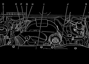
Engine Compartment Overview If the vehicle has the DURAMAX® Diesel engine, see the DURAMAX® Diesel manual for more information. When you open the hood on the 5.3L engine (4.3L, 4.8L, 6.0L and 6.2L similar), this is what you will see:
5-16
A. Engine Air Cleaner/Filter on page 5-22. B. Coolant Surge Tank and Pressure Cap.
See Cooling System on page 5-30.
C. Positive (+) Terminal. See Jump Starting on
page 5-46.
D. Battery on page 5-45. E. Engine Oil Fill Cap. See “When to Add Engine Oil”
under Engine Oil on page 5-17.
F. Automatic Transmission Dipstick. See “Checking
the Fluid Level” under Automatic Transmission Fluid (4-Speed Transmission) on page 5-24 or Automatic Transmission Fluid (6-Speed Transmission) on page 5-27.
G. Remote Negative (−) Terminal (Out of View).
See Jump Starting on page 5-46.
H. Engine Oil Dipstick (Out of View). See “Checking
Engine Oil” under Engine Oil on page 5-17.
I. Engine Cooling Fan. See Cooling System on
page 5-30.
J. Power Steering Fluid Reservoir. See Power Steering
Fluid on page 5-39.
K. Brake Master Cylinder Reservoir. See “Brake Fluid”
under Brakes on page 5-41.
L. Underhood Fuse Block on page 5-127. M. Windshield Washer Fluid Reservoir. See “Adding
Washer Fluid” under Windshield Washer Fluid on page 5-40.
Engine Oil For diesel engine vehicles, see “Engine Oil” in the DURAMAX® Diesel manual. Checking Engine Oil It is a good idea to check the engine oil level at each fuel fill. In order to get an accurate reading, the oil must be warm and the vehicle must be on level ground. The engine oil dipstick handle is a yellow loop. See Engine Compartment Overview on page 5-16
for the location of the engine oil dipstick. 1. Turn off the engine and give the oil several minutesto drain back into the oil pan. If this is not done, the oil dipstick might not show the actual level.
2. Pull out the dipstick and clean it with a paper towel or cloth, then push it back in all the way. Remove it again, keeping the tip down, and check the level.
5-17
When to Add Engine Oil
See Engine Compartment Overview on page 5-16
for the location of the engine oil fill cap.If the oil is below the cross-hatched area at the tip of the dipstick, add at least one quart/liter of the recommended oil. This section explains what kind of oil to use. For engine oil crankcase capacity, see Capacities and Specifications on page 5-131. Notice: Do not add too much oil. If the engine has so much oil that the oil level gets above the cross-hatched area that shows the proper operating range, the engine could be damaged.
Add enough oil to put the level somewhere in the proper operating range. Push the dipstick all the way back in when through.
5-18
What Kind of Engine Oil to Use Look for three things:
(cid:129) GM6094M
Use only an oil that meets GM Standard GM6094M.
(cid:129) SAE 5W-30
SAE 5W-30 is best for the vehicle. These numbers on an oil container show its viscosity, or thickness. Do not use other viscosity oils such as SAE 20W-50.
(cid:129) American Petroleum Institute (API) starburst symbol
Oils meeting these requirements should have the starburst symbol on the container. This symbol indicates that the oil has been certified by the American Petroleum Institute (API).
Notice: Use only engine oil identified as meeting GM Standard GM6094M and showing the American Petroleum Institute Certified For Gasoline Engines starburst symbol. Failure to use the recommended oil can result in engine damage not covered by the vehicle warranty. Cold Temperature Operation If in an area of extreme cold, where the temperature falls below −20°F (−29°C), use either an SAE 5W-30
synthetic oil or an SAE 0W-30 engine oil. Both provide easier cold starting for the engine at extremely low temperatures. Always use an oil that meets the required specification, GM6094M. See “What Kind of Engine Oil to Use” for more information.5-19
Engine Oil Additives / Engine Oil Flushes Do not add anything to the oil. The recommended oils with the starburst symbol that meet GM Standard GM6094M are all that is needed for good performance and engine protection. Engine oil system flushes are not recommended and could cause engine damage not covered by the vehicle warranty.
Engine Oil Life System When to Change Engine Oil This vehicle has a computer system that indicates when to change the engine oil and filter. This is based on engine revolutions and engine temperature, and not on mileage. Based on driving conditions, the mileage at which an oil change is indicated can vary considerably. For the oil life system to work properly, the system must be reset every time the oil is changed.
When the system has calculated that oil life has been diminished, it indicates that an oil change is necessary. A CHANGE ENGINE OIL SOON message comes on. See DIC Warnings and Messages on page 3-66. Change the oil as soon as possible within the next 600 miles (1 000 km). It is possible that, if driving under the best conditions, the oil life system might not indicate that an oil change is necessary for over a year. However, the engine oil and filter must be changed at least once a year and at this time the system must be reset. Your dealer/retailer has trained service people who will perform this work using genuine parts and reset the system. It is also important to check the oil regularly and keep it at the proper level. If the system is ever reset accidentally, the oil must be changed at 3,000 miles (5 000 km) since the last oil change. Remember to reset the oil life system whenever the oil is changed.
5-20
What to Do with Used Oil Used engine oil contains certain elements that can be unhealthy for your skin and could even cause cancer. Do not let used oil stay on your skin for very long. Clean your skin and nails with soap and water, or a good hand cleaner. Wash or properly dispose of clothing or rags containing used engine oil. See the manufacturer’s warnings about the use and disposal of oil products. Used oil can be a threat to the environment. If you change your own oil, be sure to drain all the oil from the filter before disposal. Never dispose of oil by putting it in the trash, pouring it on the ground, into sewers, or into streams or bodies of water. Recycle it by taking it to a place that collects used oil.
How to Reset the Engine Oil Life System The Engine Oil Life System calculates when to change the engine oil and filter based on vehicle use. Whenever the oil is changed, reset the system so it can calculate when the next oil change is required. If a situation occurs where the oil is changed prior to a CHANGE ENGINE OIL SOON message coming on, reset the system. Always reset the engine oil life to 100% after every oil change. It will not reset itself. To reset the Engine Oil Life System: 1. Display the OIL LIFE REMAINING on the DIC.
If the vehicle does not have DIC buttons, the vehicle must be in P (Park) to access this display. See DIC Operation and Displays (With DIC Buttons) on page 3-53 or DIC Operation and Displays (Without DIC Buttons) on page 3-59.
2. Press and hold the SET/RESET button on the DIC, or the trip odometer reset stem if the vehicle does not have DIC buttons, for more than five seconds. The oil life will change to 100%.
If the CHANGE ENGINE OIL SOON message comes back on when the vehicle is started, the Engine Oil Life System has not reset. Repeat the procedure.
5-21
Replacing the Engine Air Cleaner/Filter
1. Locate the air cleaner/filter assembly. See Engine
Compartment Overview on page 5-16.
2. Loosen the four screws on the cover of the housing
and lift up the cover.
Engine Air Cleaner/Filter If the vehicle has a diesel engine, see “Pickup Models” under “Engine Air Cleaner/Filter” in the DURAMAX® Diesel Supplement for the correct inspection and replacement procedures. See Engine Compartment Overview on page 5-16 for the location of the engine air cleaner/filter. When to Inspect the Engine Air Cleaner/Filter Inspect the air cleaner/filter at the Maintenance II intervals and replace it at the first oil change after each 50,000 mile (80 000 km) interval. See Scheduled Maintenance (Gasoline Engine) on page 6-4 for more information. If driving on dusty/dirty conditions, inspect the filter at each engine oil change. How to Inspect the Engine Air Cleaner/Filter To inspect the air cleaner/filter, remove the engine air cleaner/filter from the vehicle by following Steps 1
through 7. When the engine air cleaner/filter is removed, lightly shake it to release loose dust and dirt. If the engine air cleaner/filter remains caked with dirt, a new filter is required.5-22
3. Remove the engine air cleaner/filter from the housing. Care should be taken to dislodge as little dirt as possible.
4. Clean the engine air cleaner/filter sealing surfaces
and the housing.
5. Inspect or replace the engine air cleaner/filter. 6. Reinstall the cover and tighten the screws.
{ CAUTION:
Operating the engine with the air cleaner/filter off can cause you or others to be burned. The air cleaner not only cleans the air; it helps to stop flames if the engine backfires. If it is not there and the engine backfires, you could be burned. Do not drive with it off, and be careful working on the engine with the air cleaner/filter off.
5-23
Automatic Transmission Fluid (4-Speed Transmission) When to Check and Change Automatic Transmission Fluid A good time to check the automatic transmission fluid level is when the engine oil is changed. Change the fluid and filter at the intervals listed in Additional Required Services on page 6-7 and be sure to use the transmission fluid listed in Recommended Fluids and Lubricants on page 6-15. How to Check Automatic Transmission Fluid Because this operation can be a little difficult, you may choose to have this done at the dealer/retailer service department. If you do it yourself, be sure to follow all the instructions here or you could get a false reading on the dipstick. Notice: Too much or too little fluid can damage your transmission. Too much can mean that some of the fluid could come out and fall on hot engine parts or exhaust system parts, starting a fire. Too little fluid could cause the transmission to overheat. Be sure to get an accurate reading if you check your transmission fluid.
5-24
Wait at least 30 minutes before checking the transmission fluid level if you have been driving: (cid:129) When outside temperatures are above 90°F (32°C). (cid:129) At high speed for quite a while.
In heavy traffic — especially in hot weather.
(cid:129) While pulling a trailer. To get the right reading, the fluid should be at normal operating temperature, which is 180°F to 200°F (82°C to 93°C). Get the vehicle warmed up by driving about 15 miles (24 km) when outside temperatures are above 50°F (10°C). If it is colder than 50°F (10°C), drive the vehicle in 3 (Third) until the engine temperature gage moves and then remains steady for 10 minutes. A cold fluid check can be made after the vehicle has been sitting for eight hours or more with the engine off, but this is used only as a reference. Let the engine run at idle for five minutes if outside temperatures are 50°F (10°C) or more. If it is colder than 50°F (10°C), you may have to idle the engine longer. Should the fluid level be low during this cold check, you must check the fluid hot before adding fluid. Checking the fluid hot will give you a more accurate reading of the fluid level.
(cid:129) Checking the Fluid Level Prepare the vehicle as follows: 1. Park the vehicle on a level place. Keep the engine
running.
2. With the parking brake applied, place the shift lever
in P (Park).
3. With your foot on the brake pedal, move the shift lever through each gear range, pausing for about three seconds in each range. Then, position the shift lever in P (Park).
4. Let the engine run at idle for three minutes or more. Then, without shutting off the engine, follow these steps:
1. Locate the transmission dipstick handle with this graphic which is located at the rear of the engine compartment, on the passenger side of the vehicle.
See Engine Compartment Overview on page 5-16
for more information on location.2. Flip the handle up and then pull out the dipstick
and wipe it with a clean rag or paper towel.
3. Push it back in all the way, wait three seconds and
then pull it back out again.
4. Check both sides of the dipstick, and read the
lower level. The fluid level must be in the COLD area, below the cross-hatched area, for a cold check or in the HOT or cross-hatched area for a hot check. Be sure to keep the dipstick pointed down to get an accurate reading.
5. If the fluid level is in the acceptable range, push
the dipstick back in all the way; then flip the handle down to lock the dipstick in place.
5-25
Notice: Use of the incorrect automatic transmission fluid may damage the vehicle, and the damages may not be covered by the vehicle’s warranty. Always use the automatic transmission fluid listed in Recommended Fluids and Lubricants on page 6-15. (cid:129) After adding fluid, recheck the fluid level as described under “How to Check Automatic Transmission Fluid,” earlier in this section.
(cid:129) When the correct fluid level is obtained, push the
dipstick back in all the way; then flip the handle down to lock the dipstick in place.
Consistency of Readings Always check the fluid level at least twice using the procedure described previously. Consistency (repeatable readings) is important to maintaining proper fluid level. If readings are still inconsistent, contact your dealer/retailer. How to Add Automatic Transmission Fluid Refer to the Maintenance Schedule to determine what kind of transmission fluid to use. See Recommended Fluids and Lubricants on page 6-15. Using a funnel, add fluid down the transmission dipstick tube only after checking the transmission fluid while it is hot. A cold check is used only as a reference. If the fluid level is low, add only enough of the proper fluid to bring the level up to the HOT area for a hot check. It does not take much fluid, generally less than one pint (0.5 L). Do not overfill.
5-26
Automatic Transmission Fluid (6-Speed Transmission) When to Check and Change Automatic Transmission Fluid It is usually not necessary to check the transmission fluid level. The only reason for fluid loss is a transmission leak or overheating the transmission. If you suspect a small leak, then use the following checking procedures to check the fluid level. However, if there is a large leak, then it may be necessary to have the vehicle towed to a dealer/retailer service department and have it repaired before driving the vehicle further. Notice: Use of the incorrect automatic transmission fluid may damage the vehicle, and the damages may not be covered by the vehicle’s warranty. Always use the automatic transmission fluid listed in Recommended Fluids and Lubricants on page 6-15.
Change the fluid and filter at the intervals listed in the Maintenance Schedule. See Scheduled Maintenance (Gasoline Engine) on page 6-4. Be sure to use the transmission fluid listed in Recommended Fluids and Lubricants on page 6-15. How to Check Automatic Transmission Fluid Notice: Too much or too little fluid can damage your transmission. Too much can mean that some of the fluid could come out and fall on hot engine parts or exhaust system parts, starting a fire. Too little fluid could cause the transmission to overheat. Be sure to get an accurate reading if you check your transmission fluid. Before checking the fluid level, prepare the vehicle as follows: 1. Start the engine and park the vehicle on a level
surface. Keep the engine running.
2. Apply the parking brake and place the shift lever in
P (Park).
5-27
3. With your foot on the brake pedal, move the shift lever through each gear range, pausing for about three seconds in each range. Then, move the shift lever back to P (Park).
4. Allow the engine to idle (500 – 800 rpm) for at least
one minute. Slowly release the brake pedal.
5. Keep the engine running and press the Trip/Fuel
button or trip odometer reset stem until TRANS TEMP (Transmission Temperature) displays on the Driver Information Center (DIC).
6. Using the TRANS TEMP reading, determine and
perform the appropriate check procedure. If the TRANS TEMP reading is not within the required temperature ranges, allow the vehicle to cool, or operate the vehicle until the appropriate transmission fluid temperature is reached.
Cold Check Procedure Use this procedure only as a reference to determine if the transmission has enough fluid to be operated safely until a hot check procedure can be made. The hot check procedure is the most accurate method to check the fluid level. Perform the hot check procedure at the first opportunity. Use this cold check procedure to check fluid level when the transmission temperature is between 80°F and 90°F (27°C and 32°C).
1. Locate the transmission
dipstick at the rear of the engine compartment, on the passenger side of the vehicle.
See Engine Compartment Overview on page 5-16
for more information.2. Flip the handle up, and then pull out the dipstick
and wipe it with a clean rag or paper towel.
3. Install the dipstick by pushing it back in all the way, wait three seconds, and then pull it back out again.
5-28
4. Check both sides of the dipstick and read the lower
level. Repeat the check procedure to verify the reading.
5. If the fluid level is below the COLD check band, add only enough fluid as necessary to bring the level into the COLD band. It does not take much fluid, generally less than one pint (0.5L). Do not overfill.
6. Perform a hot check at the first opportunity
after the transmission reaches a normal operating temperature between 160°F to 200°F (71°C to 93°C).
7. If the fluid level is in the acceptable range, push
the dipstick back in all the way, then flip the handle down to lock the dipstick in place.
Hot Check Procedure Use this procedure to check the transmission fluid level when the transmission fluid temperature is between 160°F and 200°F (71°C and 93°C). The hot check is the most accurate method to check the fluid level. The hot check should be performed at the first opportunity in order to verify the cold check. The fluid level rises as fluid temperature increases, so it is important to ensure the transmission temperature is within range.
1. Locate the transmission
dipstick at the rear of the engine compartment, on the passenger side of the vehicle.
See Engine Compartment Overview on page 5-16
for more information.2. Flip the handle up, and then pull out the dipstick
and wipe it with a clean rag or paper towel.
3. Install the dipstick by pushing it back in all the way, wait three seconds, and then pull it back out again.
5-29
4. Check both sides of the dipstick and read the
lower level. Repeat the check procedure to verify the reading.
Consistency of Readings Always check the fluid level at least twice using the procedure described previously. Consistency (repeatable readings) is important to maintaining proper fluid level. If readings are still inconsistent, contact your dealer/retailer.
Cooling System If your vehicle has the DURAMAX® Diesel engine, see the DURAMAX® Diesel manual for more information. The Cooling System allows the engine to maintain the correct working temperature.
5. Safe operating level is within the HOT cross hatch band on the dipstick. If the fluid level is not within the HOT band, and the transmission temperature is between 160°F and 200°F (71°C and 93°C), add or drain fluid as necessary to bring the level into the HOT band. If the fluid level is low, add only enough fluid to bring the level into the HOT band. It does not take much fluid, generally less than one pint (0.5L). Do not overfill.
6. If the fluid level is in the acceptable range, push the
dipstick back in all the way, then flip the handle down to lock the dipstick in place.
5-30
{ CAUTION:
Heater and radiator hoses, and other engine parts, can be very hot. Do not touch them. If you do, you can be burned. Do not run the engine if there is a leak. If you run the engine, it could lose all coolant. That could cause an engine fire, and you could be burned. Get any leak fixed before you drive the vehicle.
Notice: Using coolant other than DEX-COOL® can cause premature engine, heater core, or radiator corrosion. In addition, the engine coolant could require changing sooner, at 50 000 km (30,000 miles) or 24 months, whichever occurs first. Any repairs would not be covered by the vehicle warranty. Always use DEX-COOL® (silicate-free) coolant in the vehicle.
5-31
5.3L Engine (4.3L, 4.8L, 6.0L and 6.2L Similar)
A. Coolant Surge Tank B. Coolant Surge Tank Pressure Cap C. Engine Cooling Fan
{ CAUTION:
An electric engine cooling fan can start even when the engine is not running. To avoid injury, always keep hands, clothing, and tools away from any engine cooling fan.
Engine Coolant The cooling system in the vehicle is filled with DEX-COOL® engine coolant. This coolant is designed to remain in the vehicle for five years or 150,000 miles (240 000 km), whichever occurs first. The following explains the cooling system and how to check and add coolant when it is low. If there is a problem with engine overheating, see Engine Overheating on page 5-36. What to Use
{ CAUTION:
Adding only plain water to the cooling system can be dangerous. Plain water, or some other liquid such as alcohol, can boil before the proper coolant mixture will. The vehicle’s coolant warning system is set for the proper coolant mixture. With plain water or the wrong mixture, the engine could get too hot but you would not get the overheat warning. The engine could catch fire and you or others could be burned. Use a 50/50 mixture of clean, drinkable water and DEX-COOL® coolant.
5-32
Use a 50/50 mixture of clean, drinkable water and DEX-COOL® coolant. If using this mixture, nothing else needs to be added. This mixture: (cid:129) Gives freezing protection down to −34°F (−37°C),
outside temperature.
(cid:129) Gives boiling protection up to 265°F (129°C),
engine temperature.
(cid:129) Protects against rust and corrosion. (cid:129) Will not damage aluminum parts. (cid:129) Helps keep the proper engine temperature. Notice: If an improper coolant mixture is used, the engine could overheat and be badly damaged. The repair cost would not be covered by the vehicle warranty. Too much water in the mixture can freeze and crack the engine, radiator, heater core, and other parts. Notice: in the vehicle’s cooling system, the vehicle could be damaged. Use only the proper mixture of the engine coolant listed in this manual for the cooling system. See Recommended Fluids and Lubricants on page 6-15 for more information.
If extra inhibitors and/or additives are used
Checking Coolant The coolant surge tank is located in the engine compartment on the passenger side of the vehicle. See Engine Compartment Overview on page 5-16
for more information on location. The vehicle must be on a level surface when checking the coolant level. Check to see if coolant is visible in the coolant surge tank. If the coolant inside the coolant surge tank is boiling, do not do anything else until it cools down. If coolant is visible but the coolant level is not at or above the FULL COLD mark, add a 50/50 mixture of clean, drinkable water and DEX-COOL® coolant at the coolant surge tank, but be sure the cooling system is cool before this is done.The coolant level should be at or above the FULL COLD mark. If it is not, you may have a leak in the cooling system. If the vehicle has a low coolant sensor and the LOW COOLANT LEVEL message comes on and stays on, it means you are low on engine coolant. See “LOW COOLANT LEVEL” under DIC Warnings and Messages on page 3-66.
5-33
How to Add Coolant to the Coolant Surge Tank for Gasoline Engines If the vehicle has a diesel engine, see “Cooling System” in the DURAMAX® Diesel Supplement for the proper coolant fill procedure.
{ CAUTION:
You can be burned if you spill coolant on hot engine parts. Coolant contains ethylene glycol and it will burn if the engine parts are hot enough. Do not spill coolant on a hot engine.
Notice: This vehicle has a specific coolant fill procedure. Failure to follow this procedure could cause the engine to overheat and be severely damaged.
{ CAUTION:
An electric engine cooling fan under the hood can start up even when the engine is not running and can cause injury. Keep hands, clothing, and tools away from any underhood electric fan.
{ CAUTION:
Steam and scalding liquids from a hot cooling system can blow out and burn you badly. They are under pressure, and if you turn the coolant surge tank pressure cap — even a little — they can come out at high speed. Never turn the cap when the cooling system, including the coolant surge tank pressure cap, is hot. Wait for the cooling system and coolant surge tank pressure cap to cool if you ever have to turn the pressure cap.
5-34
If no coolant is visible in the surge tank, add coolant as follows:
1. Remove the coolant surge tank pressure cap when the cooling system, including the coolant surge tank pressure cap and upper radiator hose, is no longer hot.
Turn the pressure cap slowly counterclockwise about one full turn. If you hear a hiss, wait for that to stop. A hiss means there is still some pressure left.
2. Keep turning the pressure cap slowly, and remove it.
3. Fill the coolant surge tank with the proper mixture
to the FULL COLD mark.
5-35
4. With the coolant surge tank pressure cap off, start the engine and let it run until the engine coolant temperature gage indicates approximately 195°F (90°C). By this time, the coolant level inside the coolant surge tank may be lower. If the level is lower, add more of the proper mixture to the coolant surge tank until the level reaches the FULL COLD mark.
5. Replace the pressure cap. Be sure the pressure
cap is hand-tight and fully seated.
6. Verify coolant level after engine is shut off and the
coolant is cold. If necessary, repeat coolant fill procedure Steps 1 through 6.
If the pressure cap is not tightly installed,
Notice: coolant loss and possible engine damage may occur. Be sure the cap is properly and tightly secured.
Engine Overheating If the vehicle has the DURAMAX® Diesel engine, see the DURAMAX® Diesel manual for more information. The vehicle has several indicators to warn of engine overheating. You will find a coolant temperature gage on the vehicle’s instrument panel. See Engine Coolant Temperature Gage (US-Canada) on page 3-44.
5-36
In addition, you will find ENGINE OVERHEATED STOP ENGINE, ENGINE OVERHEATED IDLE ENGINE, and ENGINE POWER IS REDUCED messages in the Driver Information Center (DIC) on the instrument panel. See DIC Warnings and Messages on page 3-66. You may decide not to lift the hood when this warning appears, but instead get service help right away. See Roadside Assistance Program on page 7-7. If you do decide to lift the hood, make sure the vehicle is parked on a level surface. Then check to see if the engine cooling fans are running. If the engine is overheating, both fans should be running. If they are not, do not continue to run the engine and have the vehicle serviced. Notice: Engine damage from running your engine without coolant is not covered by your warranty. See Overheated Engine Protection Operating Mode on page 5-38 for information on driving to a safe place in an emergency. Notice: with no coolant, the vehicle can be badly damaged. The costly repairs would not be covered by the vehicle warranty. See Overheated Engine Protection Operating Mode on page 5-38 for information on driving to a safe place in an emergency.
If the engine catches fire while driving
If Steam Is Coming From The Engine Compartment
{ CAUTION:
Steam from an overheated engine can burn you badly, even if you just open the hood. Stay away from the engine if you see or hear steam coming from it. Turn it off and get everyone away from the vehicle until it cools down. Wait until there is no sign of steam or coolant before you open the hood. If you keep driving when the vehicles engine is overheated, the liquids in it can catch fire. You or others could be badly burned. Stop the engine if it overheats, and get out of the vehicle until the engine is cool. See Overheated Engine Protection Operating Mode on page 5-38 for information on driving to a safe place in an emergency.
If No Steam Is Coming From The Engine Compartment The ENGINE OVERHEATED STOP ENGINE or the ENGINE OVERHEATED IDLE ENGINE message, along with a low coolant condition, can indicate a serious problem. If you get an engine overheat warning, but see or hear no steam, the problem may not be too serious. Sometimes the engine can get a little too hot when you: (cid:129) Climb a long hill on a hot day. (cid:129) Stop after high-speed driving. Idle for long periods in traffic. Tow a trailer. See Towing a Trailer on page 4-53. If you get the ENGINE OVERHEATED STOP ENGINE or the ENGINE OVERHEATED IDLE ENGINE message with no sign of steam, try this for a minute or so: 1. Turn the air conditioning off. 2. Turn the heater on to the highest temperature and
to the highest fan speed. Open the windows as necessary.
3. If you are stopped in a traffic jam, apply the brake,
shift to N (Neutral); otherwise, shift to the highest gear while driving — D (Drive) or 3 (Third).
5-37
(cid:129) (cid:129) If the temperature overheat gage is no longer in the overheat zone or an overheat warning no longer displays, the vehicle can be driven. Continue to drive the vehicle slow for about 10 minutes. Keep a safe vehicle distance from the car in front of you. If the warning does not come back on, continue to drive normally. If the warning continues, pull over, stop, and park the vehicle right away. If there is no sign of steam, idle the engine for five minutes while parked. If the warning is still displayed, turn off the engine until it cools down. Also, see “Overheated Engine Protection Operating Mode” later in this section.
Overheated Engine Protection Operating Mode If an overheated engine condition exists and the REDUCED ENGINE POWER message is displayed, an overheat protection mode which alternates firing groups of cylinders helps prevent engine damage. In this mode, you will notice a loss in power and engine performance. This operating mode allows the vehicle to be driven to a safe place in an emergency. Driving extended miles (km) and/or towing a trailer in the overheat protection mode should be avoided. Notice: After driving in the overheated engine protection operating mode, to avoid engine damage, allow the engine to cool before attempting any repair. The engine oil will be severely degraded. Repair the cause of coolant loss, change the oil and reset the oil life system. See Engine Oil on page 5-17.
5-38
Engine Fan Noise If the vehicle has a clutched engine cooling fan, when the clutch is engaged, the fan spins faster to provide more air to cool the engine. In most everyday driving conditions, the fan is spinning slower and the clutch is not fully engaged. This improves fuel economy and reduces fan noise. Under heavy vehicle loading, trailer towing, and/or high outside temperatures, the fan speed increases as the clutch more fully engages, so you may hear an increase in fan noise. This is normal and should not be mistaken as the transmission slipping or making extra shifts. It is merely the cooling system functioning properly. The fan will slow down when additional cooling is not required and the clutch disengages. You may also hear this fan noise when you start the engine. It will go away as the fan clutch partially disengages. If the vehicle has electric cooling fans, you may hear the fans spinning at low speed during most everyday driving. The fans may turn off if no cooling is required. Under heavy vehicle loading, trailer towing, and/or high outside temperatures, or if you are operating the air conditioning system, the fans may change to high speed and you may hear an increase in fan noise. This is normal and indicates that the cooling system is functioning properly. The fans will change to low speed when additional cooling is no longer required.
Power Steering Fluid
See Engine Compartment Overview on page 5-16 for reservoir location.
When to Check Power Steering Fluid It is not necessary to regularly check power steering fluid unless you suspect there is a leak in the system or you hear an unusual noise. A fluid loss in this system could indicate a problem. Have the system inspected and repaired.
5-39
How to Check Power Steering Fluid To check the power steering fluid: 1. Turn the key off and let the engine compartment
cool down.
2. Wipe the cap and the top of the reservoir clean. 3. Unscrew the cap and wipe the dipstick with a
clean rag.
4. Replace the cap and completely tighten it. 5. Remove the cap again and look at the fluid level on
the dipstick.
The level should be at the FULL COLD mark. If necessary, add only enough fluid to bring the level up to the mark. What to Use To determine what kind of fluid to use, see Recommended Fluids and Lubricants on page 6-15. Always use the proper fluid. Notice: Use of the incorrect fluid may damage the vehicle and the damages may not be covered by the vehicle’s warranty. Always use the correct fluid listed in Recommended Fluids and Lubricants on page 6-15.
5-40
Windshield Washer Fluid What to Use When windshield washer fluid needs to be added, be sure to read the manufacturer’s instructions before use. Use a fluid that has sufficient protection against freezing in an area where the temperature may fall below freezing. Adding Washer Fluid The vehicle has a low washer fluid message in the DIC that comes on when the washer fluid is low. The message is displayed for 15 seconds at the start of each ignition cycle. When the WASHER FLUID LOW ADD FLUID message displays, you will need to add washer fluid to the windshield washer fluid reservoir.
Open the cap with the washer symbol on it. Add washer fluid until the tank is full. See Engine Compartment Overview on page 5-16 for reservoir location.
Notice: (cid:129) When using concentrated washer fluid, follow
the manufacturer’s instructions for adding water. (cid:129) Do not mix water with ready-to-use washer fluid.
Water can cause the solution to freeze and damage your washer fluid tank and other parts of the washer system. Also, water does not clean as well as washer fluid. Fill the washer fluid tank only three-quarters full when it is very cold. This allows for fluid expansion if freezing occurs, which could damage the tank if it is completely full.
(cid:129) Do not use engine coolant (antifreeze) in your windshield washer. It can damage the vehicle’s windshield washer system and paint.
Brakes Brake Fluid
The brake master cylinder reservoir is filled with DOT 3 brake fluid. See Engine Compartment Overview on page 5-16 for the location of the reservoir.
There are only two reasons why the brake fluid level in the reservoir might go down:
The brake fluid level goes down because of normal brake lining wear. When new linings are installed, the fluid level goes back up.
(cid:129) A fluid leak in the brake hydraulic system can also
cause a low fluid level. Have the brake hydraulic system fixed, since a leak means that sooner or later the brakes will not work well.
5-41
(cid:129) (cid:129) Do not top off the brake fluid. Adding fluid does not correct a leak. If fluid is added when the linings are worn, there will be too much fluid when new brake linings are installed. Add or remove brake fluid, as necessary, only when work is done on the brake hydraulic system.
{ CAUTION:
If too much brake fluid is added, it can spill on the engine and burn, if the engine is hot enough. You or others could be burned, and the vehicle could be damaged. Add brake fluid only when work is done on the brake hydraulic system. See “Checking Brake Fluid” in this section.
Checking Brake Fluid Check brake fluid by looking at the brake fluid reservoir. See Engine Compartment Overview on page 5-16.
The fluid level should be above MIN. If it is not, have the brake hydraulic system checked to see if there is a leak.
Refer to the Maintenance Schedule to determine when to check the brake fluid. See Scheduled Maintenance (Gasoline Engine) on page 6-4.
After work is done on the brake hydraulic system, make sure the level is above the MIN but not over the MAX mark.
5-42
What to Add Use only new DOT 3 brake fluid from a sealed container. See Recommended Fluids and Lubricants on page 6-15. Always clean the brake fluid reservoir cap and the area around the cap before removing it. This helps keep dirt from entering the reservoir.
{ CAUTION:
With the wrong kind of fluid in the brake hydraulic system, the brakes might not work well. This could cause a crash. Always use the proper brake fluid.
Notice: (cid:129) Using the wrong fluid can badly damage brake
hydraulic system parts. For example, just a few drops of mineral-based oil, such as engine oil, in the brake hydraulic system can damage brake hydraulic system parts so badly that they will have to be replaced. Do not let someone put in the wrong kind of fluid. If brake fluid is spilled on the vehicle’s painted surfaces, the paint finish can be damaged. Be careful not to spill brake fluid on the vehicle. If you do, wash it off immediately. See Washing Your Vehicle on page 5-118.
5-43
(cid:129) Brake Wear This vehicle has front disc brakes and could have rear drum brakes or rear disc brakes. Disc brake pads have built-in wear indicators that make a high-pitched warning sound when the brake pads are worn and new pads are needed. The sound can come and go or be heard all the time the vehicle is moving, except when applying the brake pedal firmly.
{ CAUTION:
The brake wear warning sound means that soon the brakes will not work well. That could lead to an accident. When the brake wear warning sound is heard, have the vehicle serviced.
Notice: Continuing to drive with worn-out brake pads could result in costly brake repair.
Some driving conditions or climates can cause a brake squeal when the brakes are first applied or lightly applied. This does not mean something is wrong with the brakes. Properly torqued wheel nuts are necessary to help prevent brake pulsation. When tires are rotated, inspect brake pads for wear and evenly tighten wheel nuts in the proper sequence to torque specifications in Capacities and Specifications on page 5-131. If the vehicle has rear drum brakes, they do not have wear indicators, but if a rear brake rubbing noise is heard, have the rear brake linings inspected immediately. Rear brake drums should be removed and inspected each time the tires are removed for rotation or changing. Drum brakes have an inspection hole to inspect lining wear during scheduled maintenance. When the front brake pads are replaced, have the rear brakes inspected, too. Brake linings should always be replaced as complete axle sets.
5-44
Battery If the vehicle is a Two-mode Hybrid, see the Two-mode Hybrid manual for more information. This vehicle has a maintenance free battery (or batteries). When it is time for a new battery, see your dealer/retailer for one that has the replacement number shown on the original battery’s label. See Engine Compartment Overview on page 5-16 for battery location. Warning: Battery posts, terminals, and related accessories contain lead and lead compounds, chemicals known to the State of California to cause cancer and reproductive harm. Wash hands after handling.
Brake Pedal Travel See your dealer/retailer if the brake pedal does not return to normal height, or if there is a rapid increase in pedal travel. This could be a sign that brake service might be required. Brake Adjustment Every brake stop, the brakes adjust for wear. Replacing Brake System Parts The braking system on a vehicle is complex. Its many parts have to be of top quality and work well together if the vehicle is to have really good braking. The vehicle was designed and tested with top-quality brake parts. When parts of the braking system are replaced — for example, when the brake linings wear down and new ones are installed — be sure to get new approved replacement parts. If this is not done, the brakes might not work properly. For example, if someone puts in brake linings that are wrong for the vehicle, the balance between the front and rear brakes can change — for the worse. The braking performance expected can change in many other ways if the wrong replacement brake parts are installed.
5-45