- 2016 GMC Acadia Owners Manuals
- GMC Acadia Owners Manuals
- 2010 GMC Acadia Owners Manuals
- GMC Acadia Owners Manuals
- 2007 GMC Acadia Owners Manuals
- GMC Acadia Owners Manuals
- 2013 GMC Acadia Owners Manuals
- GMC Acadia Owners Manuals
- 2012 GMC Acadia Owners Manuals
- GMC Acadia Owners Manuals
- 2014 GMC Acadia Owners Manuals
- GMC Acadia Owners Manuals
- 2009 GMC Acadia Owners Manuals
- GMC Acadia Owners Manuals
- 2008 GMC Acadia Owners Manuals
- GMC Acadia Owners Manuals
- 2011 GMC Acadia Owners Manuals
- GMC Acadia Owners Manuals
- 2015 GMC Acadia Owners Manuals
- GMC Acadia Owners Manuals
- Download PDF Manual
-
eligibility. To find out more, refer to the OnStar Owner’s Guide in the vehicle’s glove box, visit onstar.com or onstar.ca, or speak with an OnStar advisor by pressing the OnStar button or calling 1-888-4-ONSTAR (1-888-466-7827).
OnStar Turn-by-Turn Navigation Vehicles with the OnStar Turn-by-Turn Navigation system can provide voice-guided driving directions. Press the OnStar button to have an OnStar advisor locate a business or address and download driving directions to the vehicle. Voice-guided directions to the desired destination will play through the audio system speakers. See the OnStar Owner’s Guide for more information.
OnStar Virtual Advisor OnStar Virtual Advisor is a feature of OnStar Hands-Free Calling that uses minutes to access location-based weather, local traffic reports, and stock quotes. Press the phone button and give a few simple voice commands to browse through the various topics.
See the OnStar Owner’s Guide for more information. This feature is only available in the continental U.S. OnStar Steering Wheel Controls This vehicle may have a Talk/Mute button that can be used to interact with OnStar Hands-Free Calling. See Audio Steering Wheel Controls on page 3-128 for more information. On some vehicles, the mute button can be used to dial numbers into voice mail systems, or to dial phone extensions. See the OnStar Owner’s Guide for more information.
2-44
Features and Controls
How OnStar Service Works The OnStar system can record and transmit vehicle information. This information is automatically sent to an OnStar Call Center when the OnStar button is pressed, the emergency button is pressed, or if the airbags or AACN system deploy. This information usually includes the vehicle’s GPS location and, in the event of a crash, additional information regarding the crash that the vehicle was involved in (e.g. the direction from which the vehicle was hit). When the Virtual Advisor feature of OnStar Hands-Free Calling is used, the vehicle also sends OnStar the vehicle’s GPS location so they can provide services where it is located.
OnStar service cannot work unless the vehicle is in a place where OnStar has an agreement with a wireless service provider for service in that area. OnStar service also cannot work unless the vehicle is in a place where the wireless service provider OnStar has hired for that area has coverage, network capacity and reception when the service is needed, and technology that is compatible with the OnStar service. Not all services are available everywhere, particularly in remote or enclosed areas, or at all times. Location information about the vehicle is only available if the GPS satellite signals are unobstructed and available. The vehicle must have a working electrical system, including adequate battery power, for the OnStar equipment to operate.
There are other problems OnStar cannot control that may prevent OnStar from providing OnStar service at any particular time or place. Some examples are damage to important parts of the vehicle in a crash, hills, tall buildings, tunnels, weather or wireless phone network congestion.
Your Responsibility Increase the volume of the radio if the OnStar advisor cannot be heard. If the light next to the OnStar buttons is red, the system may not be functioning properly. Press the OnStar button and request a vehicle diagnostic. If the light appears clear (no light is appearing), your OnStar subscription has expired and all services have been deactivated. Press the OnStar button to confirm that the OnStar equipment is active.
Universal Home Remote System The Universal Home Remote System provides a way to replace up to three hand-held Radio-Frequency (RF) transmitters used to activate devices such as garage door openers, security systems, and home lighting. This device complies with Part 15 of the FCC Rules. Operation is subject to the following two conditions: 1. This device may not cause
harmful interference.
2. This device must accept any
interference received, including interference that may cause undesired operation.
This device complies with RSS-210 of Industry Canada. Operation is subject to the following two conditions: 1. This device may not cause
interference.
2. This device must accept any
interference received, including interference that may cause undesired operation of the device.
Changes or modifications to this system by other than an authorized service facility could void authorization to use this equipment.
Features and Controls
2-45
Universal Home Remote System Operation
If there is one triangular Light Emitting Diode (LED) indicator light above the Universal Home Remote buttons, follow the instructions below. This system provides a way to replace up to three remote control transmitters used to activate devices such as garage door openers, security systems, and home automation devices.
2-46
Features and Controls
Do not use the Universal Home Remote with any garage door opener that does not have the stop and reverse feature. This includes any garage door opener model manufactured before April 1, 1982. Read the instructions completely before attempting to program the Universal Home Remote. Because of the steps involved, it may be helpful to have another person available to assist you in the programming the Universal Home Remote. Keep the original hand-held transmitter for use in other vehicles as well as for future Universal Home Remote programming. It is also recommended that upon the sale of the vehicle, the programmed Universal Home Remote buttons should be erased for security purposes. See “Erasing Universal Home Remote Buttons” later in this section.
When programming a garage door, park outside of the garage. Park directly in line with and facing the garage door opener motor-head or gate motor-head. Be sure that people and objects are clear of the garage door or gate that is being programmed. It is recommended that a new battery be installed in your hand-held transmitter for quicker and more accurate transmission of the radio-frequency signal. Programming the Universal Home Remote System For questions or help programming the Universal Home Remote System, call 1-800-355-3515 or go to www.homelink.com. Programming a garage door opener involves time-sensitive actions, so read the entire procedure before starting. Otherwise, the device will time out and the procedure will have to be repeated.
To program up to three devices:
1. From inside the vehicle, press and hold down the two outside buttons at the same time, releasing only when the Universal Home Remote indicator light begins to flash, after 20 seconds. This step will erase the factory settings or all previously programmed buttons. Do not hold down the buttons for longer than 30 seconds and do not repeat this step to program the remaining two Universal Home Remote buttons.
2. Hold the end of your hand-held transmitter about 1 to 3 inches (3 to 8 cm) away from the Universal Home Remote buttons while keeping the indicator light in view. The hand-held transmitter was supplied by the manufacturer of your garage door opener receiver (motor head unit). 3. At the same time, press and hold both the Universal Home Remote button to be used to control the garage door and the hand-held transmitter button. Do not release the Universal Home Remote button or the hand-held transmitter button until Step 4 has been completed. Some entry gates and garage door openers may require substitution of Step 3 with the procedure noted in “Gate Operator and Canadian Programming” later in this section.
4. The indicator light on the Universal Home Remote will flash slowly at first and then rapidly after Universal Home Remote successfully receives the frequency signal from the hand-held transmitter. Release both buttons.
5. Press and hold the newly-trained
Universal Home Remote button and observe the indicator light. If the indicator light stays on continuously, the programming is complete and the garage door should move when the Universal Home Remote button is pressed and released. There is no need to continue programming Steps 6 through 8. If the Universal Home Remote indicator light blinks rapidly for two seconds and then turns to a constant light, continue with the programming Steps 6
through 8.Features and Controls
2-47
It may be helpful to have another person assist with the remaining steps.
6. After Steps 1 through 5 have been completed, locate inside the garage the garage door opener receiver (motor-head unit). Locate the “Learn” or “Smart” button. The name and color of the button may vary by manufacturer.
7. Firmly press and release the
“Learn” or “Smart” button. After you press this button, you will have 30 seconds to complete Step 8.
2-48
Features and Controls
8. Immediately return to the vehicle.
Firmly press and hold the Universal Home Remote button, chosen in Step 3 to control the garage door, for two seconds, and then release it. If the garage door does not move, press and hold the same button a second time for two seconds, and then release it. Again, if the door does not move, press and hold the same button a third time for two seconds, and then release. The Universal Home Remote should now activate the garage door.
To program the remaining two Universal Home Remote buttons, begin with Step 2 of “Programming the Universal Home Remote System.” Do not repeat Step 1, as this will erase all previous programming from the Universal Home Remote buttons.
Gate Operator and Canadian Programming If you have questions or need help programming the Universal Home Remote System, call 1-800-355-3515 or go to www.homelink.com. Canadian radio-frequency laws require transmitter signals to time out or quit after several seconds of transmission. This may not be long enough for Universal Home Remote to pick up the signal during programming. Similarly, some U.S. gate operators are manufactured to time out in the same manner. If you live in Canada, or you are having difficulty programming a gate operator or garage door opener by using the “Programming Universal Home Remote” procedures, regardless of where
you live, replace Step 3 under “Programming Universal Home Remote” with the following: Continue to press and hold the Universal Home Remote button while you press and release every two seconds (cycle) the hand-held transmitter button until the frequency signal has been successfully accepted by the Universal Home Remote. The Universal Home Remote indicator light will flash slowly at first and then rapidly. Proceed with Step 4 under “Programming Universal Home Remote” to complete.
Using Universal Home Remote Press and hold the appropriate Universal Home Remote button for at least half of a second. The indicator light will come on while the signal is being transmitted.
Features and Controls
2-49
Erasing Universal Home Remote Buttons The programmed buttons should be erased when the vehicle is sold or the lease ends. To erase all programmed buttons on the Universal Home Remote device:
Reprogramming a Single Universal Home Remote Button To reprogram any of the three Universal Home Remote buttons, repeat the programming instructions earlier in this section, beginning with Step 2. For help or information on the Universal Home Remote System, call the customer assistance phone number under Customer Assistance Offices on page 7-5.
1. Press and hold down the two outside buttons until the indicator light begins to flash, after 20 seconds.
2. Release both buttons.
Storage Areas Glove Box Lift the glove box handle up to open it. Use the key to lock and unlock the glove box.
Cupholders There are two cupholders, with removable liners, located in front of the center console. There may be cupholders located in the second row seat armrest. To access, pull the armrest down. There are additional cupholders located on each side of the third row seat and in each door. There may be cupholders located at the rear of the center console. To access, pull the handle down.
Instrument Panel Storage This vehicle has an instrument panel storage area located above the radio. To open the cover, press the button.
2-50
Features and Controls
Center Console Storage
Second Row Center Console
Pull up on the lever, located on the front of the center console armrest, to slide it forward and backward. To open the armrest storage area, press the button located on the front of the armrest. There is additional storage under the armrest. Move the armrest all the way to the rear position, slide the cover back and remove the tray.
For vehicles with a second row center console, open each area to access the storage compartment inside.
To access the upper storage area, press the upper button (B) and lift up. To access the lower storage area, press the lower button (C) and lift up. The top of the console can be folded forward for increased storage area. Lift up on handle on the rear of the console (A) and pull forward.
{ CAUTION
Never open more than one of the three latches at a time to help avoid personal injury and damage to the console.
Notice: Slide the front console as far forward as it will go before folding the second row console forward to help prevent damage to the consoles.
Features and Controls
2-51
Floor Mats If the floor mat has a snap retainer, a grommet in the driver side floor mat attaches to a hook on the floor of the vehicle to secure the floor mat. To remove the floor mat, pull the mat towards the rear of the vehicle until the grommet can be removed from the hook. If the floor mat has a knob retainer, a grommet in the floor mat attaches to a knob on the floor of the vehicle to secure the floor mat. To remove the floor mat, turn the knob till it is aligned with the slot in the floor mat grommet and pull the floor mat up. To reinstall, center the slot in the floor mat grommet with the knob on the floor and set the mat in place. Then turn the knob until it is perpendicular to the slot in the grommet to lock the mat in place.
Luggage Carrier
{ CAUTION
If something is carried on top of the vehicle that is longer or wider than the luggage carrier — like paneling, plywood, or a mattress — the wind can catch it while the vehicle is being driven. This can cause a driver to lose control. The item being carried could be violently torn off, and this could cause a collision, and damage the vehicle. Items may be carried inside. Never carry something longer or wider than the luggage carrier on top of the vehicle.
The luggage carrier allows the loading of things on top of the vehicle. Crossrails are available at your dealer/retailer.
2-52
Features and Controls
Notice: Loading cargo on the luggage carrier that weighs more than 200 lbs (91 kg) or hangs over the rear or sides of the vehicle can damage the vehicle. Load cargo so that it rests as far forward as possible and against the side rails, making sure to fasten it securely. Do not exceed the maximum vehicle capacity when loading the vehicle. For more information on vehicle capacity and loading, see Loading the Vehicle on page 4-16. To prevent damage or loss of cargo while driving, check to make sure the cargo is still securely fastened.
Rear Seat Armrest Vehicles with a rear seat armrest, have two cupholders. Pull the armrest down from the rear seatback to access the cupholders.
Convenience Net Use the convenience net, located in the rear, to store small loads as far forward as possible. The net should not be used to store heavy loads.
Cargo Management System This vehicle has one of these cargo management systems located in the rear of the vehicle.
Cargo Cover For vehicles with a cargo cover, it can be used to cover items in the rear of the vehicle. To install the cover, place the loops on each corner of the cover on the four hooks in the rear of the vehicle. The cover should be stored securely when not in use.
Cargo Tie Downs Four cargo tie-downs are located in the rear compartment of the vehicle. The tie-downs can be used to secure small loads.
Cargo Management System with
a Removable Storage Area
To open, pull the handle toward the rear of the vehicle and lift the cover up.
There is an additional storage compartment on each side of the system. To open, unlatch and lift the panel up. To remove the cargo management system: 1. Open the cover. It remains open
when lifted.
2. Remove the side panels and
place inside.
3. Loosen the retaining nuts on
each side of the system by turning them counterclockwise.
4. Close the cover. 5. Pull up on the system by using the built in handles and remove it from the vehicle.
Features and Controls
2-53
{ CAUTION
An improperly latched and closed cargo cover, or cargo cover left in the open position, could be thrown about the vehicle during a collision or sudden maneuver. Someone could be injured. Be sure to return the cover to the closed position and latch before driving. If the cover is removed, always store it outside of the vehicle. When it is replaced, always be sure that it is securely reattached.
3. Remove the cover from the vehicle and store outside of the vehicle.
Cargo Management System with
a Removable Cover
To remove the cargo management cover: 1. Open the cover. It remains open
when lifted.
2. Pull the cover up making sure to unhook the hinges at the rear of the cover.
2-54
Features and Controls
Sunroof The vehicle may have a sunroof over the front seats and a rear sunroof over the second row seats. The rear sunroof does not open. The switches to operate the front sunroof and rear sunshade are located on the headliner above the rearview mirror. The ignition must be in ON/RUN or ACC/ACCESSORY to operate the sunroof. See Ignition Positions on page 2-20.
The front sunshade must be opened and closed manually. Push up on the sunshade handle to open the sunshade. Notice: The rear sunshade could be damaged if you attempt to open or close it manually. Do not manually open or close the rear sunshade. To open the rear sunshade, located over the second row seats, press and release the rear of the passenger side switch. Press and release the front of the switch to close the sunshade.
Vent: From the closed position, press and hold the front of the driver side switch to vent the sunroof. Press and hold the rear of the driver side switch to close the sunroof. Express-open/Express-close: From the closed position, press and release the rear of the driver side switch to express-open the sunroof. Press and release the front of the driver side switch to express-close the sunroof.
Instrument Panel
...................3-6
Instrument Panel Overview Instrument Panel Overview .....3-4
Hazard Warning Flashers .......3-5
Horn ....................................3-5
Tilt and Telescopic Steering Wheel Turn Signal/Multifunction Lever .................................3-6
Turn and Lane-Change Signals ...............................3-6
Headlamp High/Low-Beam Changer .............................3-7
Flash-to-Pass ........................3-7
Windshield Wipers .................3-7
Windshield Washer ................3-8
Rear Window Wiper/Washer ....3-9
......................3-9
Cruise Control Exterior Lamps ....................3-11
Delayed Headlamps .............3-12
Daytime Running Lamps (DRL)/Automatic Headlamp System ..............3-12
Fog Lamps .........................3-13Instrument Panel Brightness ...3-13
Courtesy Lamps ..................3-13
Dome Lamps ......................3-14
Dome Lamp Override ...........3-14
Entry Lighting ......................3-14
Delayed Entry Lighting .........3-14
Delayed Exit Lighting ...........3-15
Parade Dimming ..................3-15
Reading Lamps ...................3-15
Electric Power Management .....................3-15
Battery Run-Down Protection .........................3-16
Head-Up Display (HUD) ........3-16
Accessory Power Outlet(s) .....3-20
Power Outlet 115 Volt Alternating Current .............3-21Climate Controls Climate Control System ........3-22
Dual Automatic Climate Control System ..................3-25
Outlet Adjustment ................3-30
Rear Air Conditioning and Heating System .................3-31
Rear Air Conditioning and Heating System and Electronic Climate Controls ............................3-32Instrument Panel
3-1
Warning Lights, Gages, and Indicators Warning Lights, Gages, and Indicators ...................3-33
Instrument Panel Cluster .......3-34
Speedometer and Odometer .........................3-35
Tachometer ........................3-35
Safety Belt Reminders ..........3-35
Airbag Readiness Light .........3-36
Passenger Airbag Status Indicator ...........................3-36
Charging System Light .........3-37
Voltmeter Gage ...................3-38
Brake System Warning Light ................................3-38
Antilock Brake System (ABS) Warning Light ...........3-39
StabiliTrak® Indicator Light ....3-40
Engine Coolant Temperature Warning Light ....................3-40
Engine Coolant Temperature Gage .............3-41
Tire Pressure Light ..............3-41
Malfunction Indicator Lamp ..................3-42
Oil Pressure Light ................3-44
Security Light ......................3-453-2
Instrument Panel
Fog Lamp Light ...................3-45
Cruise Control Light .............3-45
Highbeam On Light ..............3-46
Tow/Haul Mode Light ...........3-46
Fuel Gage ..........................3-46
Driver Information Center (DIC) Driver Information Center (DIC) .....................3-47
DIC Operation and Displays (With DIC Buttons) .............3-47
DIC Operation and Displays (Without DIC Buttons) .........3-53
DIC Compass .....................3-56
DIC Warnings and Messages .........................3-58
DIC Vehicle Customization (With DIC Buttons) ..............3-67Audio System(s) Audio System(s) ..................3-76
Setting the Clock .................3-76
Radio(s) .............................3-77
Using an MP3
(Radio with CD) .................3-94
Using an MP3 (Radio with CD and DVD Player) ..........3-99
XM Radio Messages ..........3-104
Navigation/Radio System .....3-105
Bluetooth® ........................3-105
Rear Seat Entertainment (RSE) System ..................3-116
Rear Seat Audio (RSA) ......3-125
Rear Audio Controller (RAC) ...............3-127
Theft-Deterrent Feature .......3-127
Audio Steering Wheel Controls ..........................3-128
Radio Reception ................3-128
Multi-Band Antenna ............3-129Instrument Panel
3-3
✍ NOTES
3-4
Instrument Panel
Instrument Panel Overview
The main components of the instrument panel are listed here: A. Outlet Adjustment on page 3-30. B. Turn Signal/Multifunction Lever on page 3-6. Windshield Wipers on page 3-7.
C. Instrument Panel Cluster on
page 3-34.
D. Head-Up Display (HUD) on
page 3-16 (If Equipped).
E. Audio System(s) on page 3-76.
Navigation/Radio System on page 3-105 (If Equipped).
F. Exterior Lamps on page 3-11. G. Hood Release on page 5-11. H. Dome Lamp Override on
page 3-14. Instrument Panel Brightness on page 3-13. Windshield Washer on page 3-8
(If Equipped).I. Cruise Control on page 3-9. J. Tilt and Telescopic Steering
Wheel on page 3-6. K. Horn on page 3-5.
Instrument Panel
3-5
L. Audio Steering Wheel Controls
on page 3-128.
T. Heated Seats on page 1-5
(If Equipped).
M. Driver Information Center (DIC)
on page 3-47.
N. Dual Automatic Climate Control
System on page 3-25.
O. Center Console Shift Lever
(If Equipped). See “Console Shift Lever” under Shifting Into Park on page 2-28.
P. Hazard Warning Flashers on
page 3-5.
Q. Cupholders on page 2-49. R. Accessory Power Outlet(s) on
page 3-20.
S. Rear Window Wiper/Washer on page 3-9. Traction Control System (TCS) Disable Button. See StabiliTrak® System on page 4-5. Tow/Haul Mode on page 2-26 (If Equipped). Power Liftgate on page 2-11
(If Equipped).U. Passenger Air Bag status Indicator. See Passenger Sensing System on page 1-57.
V. Glove Box on page 2-49.
Hazard Warning Flashers | Hazard Warning Flasher: Press this button located on the instrument panel below the audio system, to make the front and rear turn signal lamps flash on and off. This warns others that you are having trouble. Press again to turn the flashers off. The turn signals do not work while the hazard warning flashers are on.
Horn Press near or on the horn symbols on the steering wheel pad to sound the horn.
3-6
Instrument Panel
Tilt and Telescopic Steering Wheel The steering wheel can be adjusted.
The adjustment lever is located on the left side of the steering column. Pull the lever down to move the steering wheel up or down and in or out. Pull the lever up to lock the steering wheel in place. Do not adjust the steering wheel while driving.
Turn Signal/Multifunction Lever
Turn and Lane-Change Signals
The lever on the left side of the steering column includes the following: G : Turn and Lane-Change Signals 3 : Headlamp High/Low-Beam Changer N : Windshield Wipers L : Windshield Washer Flash-to-Pass Feature. Information for these features is on the pages following. For information on the headlamps, see Exterior Lamps on page 3-11.
An arrow on the instrument panel cluster flashes in the direction of the turn or lane change. Move the lever all the way up or down to signal a turn. Raise or lower the lever until the arrow starts to flash to signal a lane change. Hold it there until the lane change is completed. If the lever is briefly pressed and released, the turn signal flashes three times. The lever returns to its starting position whenever it is released. If after signaling a turn or lane change the arrow flashes rapidly or does not come on, a signal bulb might be burned out. Have the bulbs replaced. If the bulb is not burned out, check the fuse. See Fuses and Circuit Breakers on page 5-88.
Turn Signal On Chime If either one of the turn signals are left on and the vehicle has been driven more than 3/4 mile (1.2 km), a chime will sound.
Headlamp High/ Low-Beam Changer 2 3 Headlamp High/Low Beam Changer: Push the turn signal/multifunction lever away from you to turn the high beams on.
Pull the lever towards you to return to low beams.
This indicator light turns on in the instrument panel cluster when the high beam headlamps are on.
Flash-to-Pass With the turn signal lever in the low-beam position, pull the lever toward you momentarily to switch to high-beam, to signal that you are going to pass. If the headlamps are on, they will return to low-beam when the lever is released. For vehicles with High Intensity Discharge (HID) headlamps, the flash-to-pass feature does not work while the Daytime Running Lamps (DRL) are on. Windshield Wipers The windshield wiper/washer lever is located on the right side of the steering column. Turn the band with the wiper symbol to control the windshield wipers. 8 (Mist): Turn the band to mist for a single wiping cycle and then release. The wipers stop after one wipe. Hold the band on 8 longer, for more wipe cycles.
Instrument Panel
3-7
9 (Off): Turns the wipers off.
6 (Delay): Adjusts the delay time. The delay between wiping cycles becomes shorter as the band is moved to the top of the lever. 1 (Low Speed): For steady wiping at low speed. 2 (High Speed): For steady wiping at high speed. Clear ice and snow from the wiper blades before using them. If the blades are frozen to the windshield, gently loosen or thaw them. If they become damaged, install new blades or blade inserts. See Windshield Wiper Blade Replacement on page 5-36. Heavy snow or ice can overload the wipers. A circuit breaker stops them until the motor cools.
3-8
Instrument Panel
Windshield Washer J (Washer Fluid): Press the button located at the end of the turn signal/multifunction lever, to spray washer fluid on the windshield. The wipers clear the windshield and either stop or return to the preset speed. The ignition key must be in ACC/ACCESSORY or ON/RUN for this to work. See Windshield Washer Fluid on page 5-26
Windshield Washer Fluid. { CAUTIONIn freezing weather, do not use your washer until the windshield is warmed. Otherwise the washer fluid can form ice on the windshield, blocking your vision.
WASHER FLUID LOW ADD FLUID is displayed on the Driver Information Center (DIC) when the washer fluid is low. See DIC Warnings and Messages on page 3-58.
Heated Windshield Washer For vehicles with the heated windshield washer fluid system, it helps to clear ice, snow, tree sap, or bugs from the windshield. This feature only works with the front wiper system.
The button is located to the left of the steering column below the instrument panel brightness control knob. Press the heated washer fluid button to activate the heated windshield washer fluid system. This activation begins four heated wash/wipe cycles. The first heated wash/wipe
cycle can take up to 40 seconds to occur, depending on outside temperature. After the first wash/ wipe cycle, it can take up to 20 seconds for each of the remaining cycles. The system turns off automatically after four wipe cycles or the button can be pressed again to turn it off. Under certain outside temperature conditions, steam might flow out of the washer nozzles for a short period of time before washer fluid is sprayed. This is normal. HEATING WASH FLUID WASH WIPES PENDING is displayed on the DIC when the washer system is heating the fluid. WASHER FLUID LOW ADD FLUID is displayed when the washer fluid is low. See DIC Warnings and Messages on page 3-58.
Rear Window Wiper/ Washer The rear wiper and rear wash button is located on the instrument panel below the climate control system. Z (Rear Wiper): Press to turn the rear wiper on and off. The wiper speed cannot be changed. Y (Wash): Press to spray washer fluid on the rear window. The window wiper will also come on. Release the button when enough fluid has been sprayed on the window. The rear wiper will run a few more cycles after it is released. If the rear wiper function was already on, prior to pressing the wash button, it stays on until the wiper button is pressed again. The rear window washer uses the same fluid that is in the windshield washer reservoir. See Windshield Washer Fluid on page 5-26.
Cruise Control With cruise control, a speed of about 25 mph (40 km/h) or more can be maintained without keeping your foot on the accelerator. Cruise control does not work at speeds below about 25 mph (40 km/h). When the brakes are applied, the cruise control is disengaged.
{ CAUTION
Cruise control can be dangerous where you cannot drive safely at a steady speed. So, do not use the cruise control on winding roads or in heavy traffic. Cruise control can be dangerous on slippery roads. On such roads, fast changes in tire traction can cause excessive wheel slip, and you could lose control. Do not use cruise control on slippery roads.
Instrument Panel
3-9
The cruise control buttons are located on left side of the steering wheel. T (On/Off): Press to turn cruise control on and off. The indicator comes on when cruise control is on. + RES (Resume/Accelerate): Press to make the vehicle accelerate or resume to a previously set speed. SET– : Press to set the speed or make the vehicle decelerate.
[ (Cancel): Press to cancel cruise control.
3-10
Instrument Panel
Setting Cruise Control Cruise control will not work if the parking brake is set, or if the master cylinder brake fluid level is low. The cruise control light on the instrument panel cluster comes on after the cruise control has been set to the desired speed.
{ CAUTION
If you leave your cruise control on when you are not using cruise, you might hit a button and go into cruise when you do not want to. You could be startled and even lose control. Keep the cruise control switch off until you want to use cruise control. 1. Press the I button. 2. Get up to the speed desired. 3. Press and release the
SET– button located on the steering wheel.
4. Take your foot off the
accelerator.
Resuming a Set Speed If the cruise control is set at a desired speed and then the brakes are applied, the cruise control is disengaged. But it does not need to be reset. Once the vehicle speed is 25 mph (40 km/h) or greater, press the +RES button on the steering wheel. The vehicle returns to the previously set speed and stays there. Increasing Speed While Using Cruise Control There are two ways to increase the vehicle speed while using cruise control: (cid:129) Press and hold the +RES button
on the steering wheel until the desired speed is reached, then release it. To increase vehicle speed in small increments, press the +RES button briefly. Each time this is done, the vehicle goes about 1 mph (1.6 km/h) faster.
Reducing Speed While Using Cruise Control There are two ways to reduce the vehicle speed while using cruise control: (cid:129) Press and hold the SET– button
on the steering wheel until the lower speed desired is reached, then release it. To slow down in very small amounts, press the SET– button briefly. Each time this is done, the vehicle goes about 1 mph (1.6 km/h) slower.
Passing Another Vehicle While Using Cruise Control Use the accelerator pedal to increase vehicle speed. When you take your foot off the pedal, the vehicle will slow down to the previously set cruise speed.
(cid:129) (cid:129) Using Cruise Control on Hills How well the cruise control will work on hills depends upon the vehicle speed, load, and the steepness of the hills. When going up steep hills, you might have to step on the accelerator pedal to maintain the vehicle speed. When going downhill, you might have to brake or shift to a lower gear to keep the vehicle speed down. When the brakes are applied the cruise control is disengaged.
Ending Cruise Control There are three ways to end cruise control: (cid:129) Step lightly on the brake pedal. (cid:129) Press the [ button. (cid:129) Press the T button. Erasing Speed Memory The cruise control set speed memory is erased when the cruise control or the ignition is turned off.
Exterior Lamps
The exterior lamps control is located on the instrument panel to the left of the steering wheel. It controls the following systems: (cid:129) Headlamps
Taillamps
(cid:129) Parking Lamps
License Plate Lamps Instrument Panel Lights Fog Lamps
Instrument Panel
3-11
The exterior lamps control has four positions: 9 (Off): Briefly turn to this position to turn the automatic light control off or on again. AUTO (Automatic): Turns the headlamps on automatically at normal brightness, together with the following: (cid:129) Parking Lamps
Taillamps License Plate Lamps Instrument Panel Lights
; (Parking Lamps): Turns the parking lamps on together with the following:
Taillamps License Plate Lamps Instrument Panel Lights
(cid:129) (cid:129) (cid:129) (cid:129) (cid:129) (cid:129) (cid:129) (cid:129) (cid:129) (cid:129) 3-12
Instrument Panel
2 (Headlamps): Turns the headlamps on together with the following lamps listed below. A warning chime sounds if the driver’s door is opened when the ignition switch is off and the headlamps are on. (cid:129) Parking Lamps
Taillamps License Plate Lamps Instrument Panel Lights
# (Fog Lamps): Push the fog lamps control in to turn on the fog lamps.
See Fog Lamps on page 3-13.
Delayed Headlamps Delayed headlamps provide a period of exterior lighting as you leave the area around your vehicle. This feature is activated when the headlamps are on due to the automatic headlamps control feature, and when the ignition is turned off. The headlamps remain on until the exterior lamps control is moved to the parking lamps position or until the pre-selected delayed headlamp lighting period has ended. If the ignition is turned off with the headlamps switch in the parking lamps or headlamps position, the delayed headlamps cycle will not occur. To disable the delayed headlamps feature or change the time of delay, see DIC Vehicle Customization (With DIC Buttons) on page 3-67.
Daytime Running Lamps (DRL)/Automatic Headlamp System Daytime Running Lamps (DRL) can make it easier for others to see the front of your vehicle during the day. Fully functional daytime running lamps are required on all vehicles first sold in Canada. The DRL system makes either the low-beam headlamps come on at a reduced brightness or the DRL lights, for vehicles with High Intensity Discharge (HID) headlamps when the following conditions are met: The ignition is in the ON/RUN position. The exterior lamps control is in AUTO. The engine is running.
(cid:129) (cid:129) (cid:129) (cid:129) (cid:129) (cid:129) When the DRL are on, the regular headlamps, taillamps, sidemarker, and other lamps will not be on. The instrument panel and cluster will also not be lit. For vehicles with HID headlamps, if the DRL are on and the left or right turn signal lamp is turned on, the left or right DRL will go off. The headlamps automatically change from DRL to the regular headlamps depending on the darkness of the surroundings. The other lamps that come on with the headlamps will also come on. When it is bright enough outside, the headlamps will go off and the DRL will come on. The regular headlamp system should be turned on when needed. Do not cover the light sensor on top of the instrument panel because it works with the DRL.
Fog Lamps Use the fog lamps for better vision in foggy or misty conditions. The fog lamps button is located on the exterior lamps control to the left of the steering column. # (Fog Lamps): Press the exterior lamps button to turn the fog lamps on or off. A light comes on in the instrument panel cluster when the fog lamps are in use. The ignition must be on for the fog lamps to work. When the headlamps are changed to high-beam, the fog lamps will turn off. The fog lamps come back on again when the high-beam headlamps are turned off. Some localities have laws that require the headlamps to be on along with the fog lamps.
Instrument Panel
3-13
Instrument Panel Brightness D (Instrument Panel Brightness): The knob with this symbol on it is located next to the exterior lamps control to the left of the steering wheel. Push the knob in all the way until it extends out and then turn the knob clockwise or counterclockwise to brighten or dim the lights. Push the knob back in when finished. Courtesy Lamps When a door is opened, the courtesy lamps automatically come on. They make it easier when entering and exiting the vehicle. The lamps can also be turned on manually by fully turning the instrument panel brightness control clockwise. The reading lamps, located on the headliner above the rearview mirror, can be turned on or off independent of the automatic courtesy lamps, when the doors are closed.
3-14
Instrument Panel
Dome Lamps The dome lamps automatically come on when a door is opened, unless the dome lamp override button is pressed in. The lamps can also be turned on and off by turning the instrument panel brightness control clockwise to the farthest position.
Dome Lamp Override The dome lamp override button is located next to the exterior lamps control. The dome lamp override sets the dome lamps to remain off or come on automatically when a door is opened. E (Dome Lamp Override): Press the button in and the dome lamps remain off when a door is opened. Press the button again to return it to the extended position so that the dome lamps come on when a door is opened.
Entry Lighting For vehicles with courtesy lamps, they come on and stay on for a set time whenever the unlock symbol is pressed on the Remote Keyless Entry (RKE) transmitter, if the vehicle has one. If a door is opened, the lamps stay on while it is open and then turn off automatically about 20 seconds after the door is closed. If the unlock symbol is pressed and no door is opened, the lamps turn off after about 20 seconds. Entry lighting includes a feature called theater dimming. With theater dimming, the lamps do not turn off at the end of the delay time. Instead, they slowly dim and then go out. The delay time is canceled if the ignition key is turned to ON/RUN or the power door lock switch is pressed. The lamps will dim right away. When the ignition is on, illuminated entry is inactive, which means the courtesy lamps will not come on unless a door is opened.
Delayed Entry Lighting Delayed entry lighting illuminates the interior for a period of time after all the doors have been closed. The ignition must be off for delayed entry lighting to work. Immediately after all the doors have been closed, the delayed entry lighting feature continues to work until one of the following occurs:
The ignition is in ON/RUN. The doors are locked.
(cid:129) An illumination period of about
25 seconds has elapsed.
If during the illumination period a door is opened, the timed illumination period is canceled and the interior lamps remain on.
(cid:129) (cid:129) Delayed Exit Lighting This feature illuminates the interior for a period of time after the key is removed from the ignition. The ignition must be off for delayed exit lighting to work. When the key is removed, interior illumination activates and remains on until one of the following occurs:
The ignition is in ON/RUN. The power door locks are activated.
(cid:129) An illumination period of 20 seconds has elapsed.
If during the illumination period a door is opened, the timed illumination period will be canceled and the interior lamps will remain on because a door is open.
Parade Dimming Parade mode automatically prohibits the dimming of the instrument panel displays during the daylight while the headlamps are on so that the displays are still able to be seen.
Reading Lamps The vehicle has reading lamps that also act as the dome lamp. Press the button to turn them on and off.
Electric Power Management The vehicle has Electric Power Management (EPM) that estimates the battery’s temperature and state of charge. It then adjusts the voltage for best performance and extended life of the battery. When the battery’s state of charge is low, the voltage is raised slightly to quickly bring the charge back up.
Instrument Panel
3-15
When the state of charge is high, the voltage is lowered slightly to prevent overcharging. If the vehicle has a voltmeter gage or a voltage display on the Driver Information Center (DIC), you may see the voltage move up or down. This is normal. If there is a problem, an alert will be displayed. The battery can be discharged at idle if the electrical loads are very high. This is true for all vehicles. This is because the generator (alternator) may not be spinning fast enough at idle to produce all the power that is needed for very high electrical loads. A high electrical load occurs when several of the following are on, such as: headlamps, high beams, fog lamps, rear window defogger, climate control fan at high speed, heated seats, engine cooling fans, trailer loads, and loads plugged into accessory power outlets.
(cid:129) (cid:129) 3-16
Instrument Panel
EPM works to prevent excessive discharge of the battery. It does this by balancing the generator’s output and the vehicle’s electrical needs. It can increase engine idle speed to generate more power, whenever needed. It can temporarily reduce the power demands of some accessories. Normally, these actions occur in steps or levels, without being noticeable. In rare cases at the highest levels of corrective action, this action may be noticeable to the driver. If so, a Driver Information Center (DIC) message might be displayed, such as BATTERY SAVER ACTIVE, BATTERY VOLTAGE LOW, or LOW BATTERY. If this message is displayed, it is recommended that the driver reduce the electrical loads as much as possible. See DIC Warnings and Messages on page 3-58.
Battery Run-Down Protection This feature helps prevent the battery from being drained, if the interior courtesy lamps, reading/map lamps, visor vanity lamps or trunk lamp are accidentally left on. If any of these lamps are left on, they automatically turn off after 10 minutes, if the ignition is off. The lamps will not come back on again until one of the following occurs:
The ignition is turned on. The exterior lamps control is turned off, then on again.
The headlamps will timeout after 10 minutes, if they are manually turned on with the ignition on or off.
Head-Up Display (HUD)
{ CAUTION
If the HUD image is too bright or too high in your field of view, it may take you more time to see things you need to see when it is dark outside. Be sure to keep the HUD image dim and placed low in your field of view.
For vehicles with the Head-Up Display (HUD), some information concerning the operation of the vehicle is projected onto the windshield. This includes the speedometer reading, RPM reading, transmission position, outside air temperature, the tap shift gear, and a brief display of the current radio station, including XM information or CD track.
(cid:129) (cid:129) It will also display turn-by-turn navigation information if the vehicle has a navigation radio. The images are projected by the HUD lens located on the driver’s side of the instrument panel. The tap shift gear will also appear on the HUD if the vehicle has tap shift and it is active. The HUD information can be displayed in one of three languages, English, French, or Spanish. The speedometer reading and other numerical values can be displayed in either English or metric units. The language selection and the units of measurement are changed through the trip computer in the Driver Information Center (DIC). See DIC Vehicle Customization (With DIC Buttons) on page 3-67.
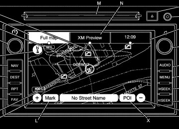
HUD Display on the Vehicle
Windshield
The HUD information appears as an image focused out toward the front of the vehicle. When the ignition key is turned to ON/RUN, the HUD will display an introductory message for a short time, until the HUD is ready.
Instrument Panel
3-17
The following indicator lights come on the instrument panel when activated and also appear on the HUD:
Turn Signal Indicators
(cid:129) High-Beam Indicator Symbol The HUD temporarily displays CHECK GAGES and ICE POSSIBLE when these messages are on the DIC trip computer. The HUD also displays the following messages on vehicles with these systems, when they are active:
TRACTION CONTROL ACTIVE
If you try to use the
(cid:129) STABILITRAK ACTIVE Notice: HUD image as a parking aid, you may misjudge the distance and damage your vehicle. Do not use the HUD image as a parking aid.
(cid:129) (cid:129) 3-18
Instrument Panel
When the HUD is on, the speedometer reading is continually displayed. The current radio station or CD track number will display for a short period of time after the radio or CD track status changes. This happens whenever radio information is changed. The speedometer size is reduced when radio, CD information, warnings, or turn-by-turn navigation information are displayed on the HUD.
The HUD control is located to the right of the steering wheel.
To adjust the HUD image so that items are properly displayed, do the following: 1. Adjust the driver’s seat to a
comfortable position.
2. Start the engine. 3. Adjust the HUD controls. Use the following settings to adjust the HUD. 9 (Off): To turn HUD off, rotate the dimming knob fully counterclockwise until the HUD display turns off. Brightness: Turn the knob on the HUD control clockwise or counterclockwise to brighten or dim the display. w (Up): x (Down): Press the up or down arrows to center the HUD image in your view. The HUD image can only be adjusted up and down, not side to side. ? (Page): Press this button to select the display formats. Release the page button when the format number with the desired display is shown on the HUD.
The three formats are as follows:
Format One: This display gives the speedometer reading (in English or metric units), turn signal indication, high beam indication, transmission positions, and the outside air temperature.
Format Two: This display includes the information in Format One without the transmission information and the outside air temperature.
The HUD image displayed on the windshield will automatically dim and brighten to compensate for outside lighting. The HUD image can temporarily light up depending on the angle and position of the sunlight on the HUD display. This is normal and will change when the angle of the sunlight on the HUD display changes. Polarized sunglasses could make the HUD image harder to see.
Care of the HUD Clean the inside of the windshield as needed to remove any dirt or film that could reduce the sharpness or clarity of the HUD image. To clean the HUD lens, use a soft, clean cloth that has household glass cleaner sprayed on it. Wipe the HUD lens gently, then dry it. Do not spray cleaner directly on the lens because the cleaner could leak into the unit.
Instrument Panel
3-19
If You Cannot See the HUD Image When the Ignition Is On
Is anything covering the HUD lens? Is the HUD dimmer setting bright enough? Is the HUD image adjusted to the proper height?
(cid:129) Are you wearing polarized
sunglasses?
(cid:129) Still no HUD image? Check the fuse in the instrument panel fuse block. See Instrument Panel Fuse Block on page 5-88.
If the HUD Image Is Not Clear
Is the HUD image too bright? (cid:129) Are the windshield and HUD
lens clean?
If the HUD image is not correct, contact your dealer/retailer. Keep in mind that the windshield is part of the HUD system.
Format Three: This display includes all the information in Format One along with a circular tachometer, but without outside air temperature. All formats will show the turn-by-turn navigation information and provide details about the next driving maneuver to be made. When you near your destination, the HUD will display a distance bar that will fill in the closer you get to your destination. All navigation information is provided to the HUD by the navigation radio, if the vehicle has one.
(cid:129) (cid:129) (cid:129) (cid:129) 3-20
Instrument Panel
Accessory Power Outlet(s) The vehicle has three 12-volt outlets which can be used to plug in electrical equipment, such as a cellular telephone, a compact disc player, etc. The power outlets are located on the instrument panel below the climate controls, at the rear of the center console, and in the rear cargo area. Lift the cover to access the outlet. Close the cover when not using the outlet. Notice: Leaving electrical equipment plugged in for an extended period of time while the vehicle is off will drain the battery.
Power is always supplied to the outlets. Always unplug electrical equipment when not in use and do not plug in equipment that exceeds the maximum 20 ampere rating. Certain accessory plugs may not be compatible to the accessory power outlet and could result in blown vehicle and adapter fuses. If a problem is experienced, see your dealer/retailer for additional information on the power accessory outlets. Notice: Adding any electrical equipment to the vehicle can damage it or keep other components from working as they should. The repairs would
not be covered by the vehicle warranty. Do not use equipment exceeding maximum amperage rating of 20 amperes. Check with your dealer/retailer before adding electrical equipment. When adding electrical equipment, be sure to follow the proper installation instructions included with the equipment. Notice: power outlet can cause damage not covered by the warranty. Do not hang any type of accessory or accessory bracket from the plug because the power outlets are designed for accessory power plugs only.
Improper use of the
Power Outlet 115 Volt Alternating Current For vehicles with this power outlet, it can be used to plug in electrical equipment that uses a maximum limit of 150 watts.
The power outlet is located on the rear of the center console.
An indicator light on the outlet turns on to show it is in use. The light comes on when the ignition is in ON/RUN and equipment requiring less than 150 watts is plugged into the outlet, and no system fault is detected. The indicator light does not come on when the ignition is in LOCK/OFF or if no equipment is plugged into the outlet. If equipment is connected using more than 150 watts or a system fault is detected, a protection circuit shuts off the power supply and the indicator light turns off. To reset the circuit, unplug the item and plug it back in or turn the Remote Accessory Power (RAP) off and then back on. See Retained Accessory Power (RAP) on page 2-21. The power restarts when equipment using 150 watts or less is plugged into the outlet and a system fault is not detected.
Instrument Panel
3-21
The power outlet is not designed for the following electrical equipment and may not work properly if these items are plugged into the power outlet: (cid:129) Equipment with high
initial peak wattage such as: compressor-driven refrigerators and electric power tools.
(cid:129) Other equipment
requiring an extremely stable power supply such as: microcomputer-controlled electric blankets, touch sensor lamps, etc.
See High Voltage Devices and Wiring on page 5-87.
3-22
Instrument Panel
Climate Controls Climate Control System The heating, cooling, and ventilation in the vehicle can be controlled with this system.
A. Fan Control B. Temperature Control C. Air Delivery Mode Control D. Air Conditioning E. REAR (Rear Climate Control) F. Recirculation G. Rear Window Defogger
9 (Off): Turn the fan control all the way counterclockwise to turn the front climate control system off. 9 (Fan Control): Turn clockwise or counterclockwise to increase or decrease the fan speed.
Temperature Control: Turn clockwise or counterclockwise to increase or decrease the temperature of the air flowing from the system. Air Delivery Mode Control: Turn clockwise or counterclockwise to change the current airflow mode.
By positioning the right knob between two modes, a combination of those two modes is selected. H (Vent): Air is directed to the instrument panel outlets. ) (Bi-Level): Air is divided between the instrument panel and floor outlets. Some air is directed towards the windshield and side window outlets. Cooler air is directed to the upper outlets and warmer air to the floor outlets.
6 (Floor): Air is directed to the floor outlets, with some of the air directed to the windshield, side window, and second row floor outlets. In this mode, the system automatically selects outside air. Recirculation cannot be selected while in floor mode. - (Defog): This mode clears the windows of fog or moisture. Air is directed to the windshield, floor outlets, and side window vents. When this mode is selected, the system turns off recirculation and runs the air conditioning unless the outside temperature is less than 40°F (4°C). Recirculation cannot be selected while in the defog mode. Do not drive the vehicle until all the windows are clear.
0 (Defrost): This mode quickly clears the windshield of fog or frost. Air is directed to the windshield and side window vents, with some to the floor vents. In this mode, outside air is pulled inside the vehicle. Recirculation cannot be selected while in the defrost mode. The air conditioning system runs automatically in this setting, unless the outside temperature is less than 40°F (4°C). Do not drive the vehicle until all the windows are clear. # (Air Conditioning): Press to turn the air conditioning system on or off. An indicator light comes on when A/C is on. The air conditioning system does not operate when the outside temperature is below 40°F (4°C). The indicator light flashes three times and turns off when outside conditions affect air conditioning operation. This is normal.
Instrument Panel
3-23
For quicker cool down on hot days: 1. Open the windows to let hot
air escape.
2. Select H mode. 3. Select #. 4. Select the coolest temperature. 5. Select the highest fan speed. 6. Close the windows after the hot
air has escaped.
7. Once the vehicle’s interior
temperature is below the outside temperature, select @ mode for faster cooling.
Using recirculation for long periods of time could cause the air inside of the vehicle to become too dry. To prevent this from happening, after the inside of the vehicle has cooled, turn the recirculation mode off. The air conditioning system removes moisture from the air, so a small amount of water might drip under the vehicle while idling or after turning off the engine. This is normal.
3-24
Instrument Panel
@ (Recirculation): Press to turn the recirculation mode on or off. An indicator light comes on when recirculation is on. When the engine is turned off, the recirculation mode automatically turns off and must be re-selected when the engine is turned on again.
This mode recirculates and helps to quickly cool the air inside the vehicle. It can be used to prevent outside air and odors from entering the vehicle.
The recirculation mode cannot be used with floor, defrost, or defogging modes. If recirculation is selected in these modes, the indicator flashes three times and turns off. The air conditioning also comes on when this mode is activated unless the outside air temperature is less than 40°F (4°C). While in recirculation mode the windows can fog when the weather is cold and damp. To clear the fog, select either the defog or defrost mode and increase the fan speed.
REAR (Rear Climate Control): Press to turn the rear heating and air conditioning on or off. See Rear Air Conditioning and Heating System on page 3-31 or Rear Air Conditioning and Heating System and Electronic Climate Controls on page 3-32.
Rear Window Defogger The rear window defogger uses a warming grid to remove fog from the rear window. < (Rear Window Defogger): Press to turn the rear window defogger on or off. The rear window defogger stays on for about 10 minutes, before automatically turning off. The defogger will also turn off when the engine is turned off.
Do not drive the vehicle until all the windows are clear. For vehicles with heated outside rearview mirrors, fog or frost is cleared from the surface of the mirror when < is pressed. Notice: Do not use anything sharp on the inside of the rear window. If you do, you could cut or damage the warming grid, and the repairs would not be covered by the vehicle warranty. Do not attach a temporary vehicle license, tape, a decal or anything similar to the defogger grid.
Dual Automatic Climate Control System The heating, cooling, and ventilation in the vehicle can be controlled with this system.
A. Fan Control B. AUTO C. Defrost D. Recirculation E. REAR (Rear Climate Control) F. Air Delivery Mode Control G. Driver Side Temperature Control
H. Display I. Power (On/Off) J. Rear Window Defogger K. Air Conditioning L. PASS (Passenger) M. Passenger Side Temperature
Control
Instrument Panel
3-25
Display Function Each time the temperature, mode, or fan control buttons are pressed, the climate control display shows that function along with the inside temperature setting. The outside temperature is displayed on the instrument panel cluster. O (On/Off): Press to turn the climate control system on or off. While the system is off, outside air still enters through the floor outlets, but the air delivery mode can be adjusted.
The climate control system will also turn on if either the fan control, defrost, AUTO, or air conditioning buttons are pressed.
3-26
Instrument Panel
Automatic Operation AUTO (Automatic): The system automatically controls the inside temperature, the air delivery, and the fan speed. To use automatic mode: 1. Press the AUTO button.
When AUTO is selected, the current temperature(s) selected and AUTO is shown on the display. The current air delivery mode and fan speed also appear for approximately five seconds. When AUTO is selected, the air conditioning and air inlet are automatically controlled. The air conditioning runs when the outside temperature is over 40°F (4°C). The system is automatically set to outside air, unless it is hot outside and then the air inlet changes to recirculation mode to help quickly cool the vehicle. The recirculation indicator light will come on.
2. Set the temperature for the driver
and passenger. To find a comfortable setting, start with a 73°F (22°C) temperature setting and allow about 20 minutes for the system to regulate. Use the driver’s side or passenger side temperature buttons to adjust the temperature setting as necessary. The system will remain at the selected setting. Choosing the warmest or coolest temperatures does not cause the vehicle to heat or cool more quickly. To avoid blowing cold air in cold weather, the system delays turning on the fan until warm air is available. Press the fan control to override this delay and select the fan speed.
Temperature Control The driver and passenger side temperature buttons are used to adjust the temperature of the air coming through the system. The temperature can be adjusted even if the system is turned off since outside air still enters the vehicle, unless the recirculation mode is selected. See “Recirculation” later in this section. Driver Side Temperature Control: Press the + or − buttons to increase or decrease the driver side temperature. The driver side temperature display will show the temperature setting. Passenger Side Temperature Control: Press the + or − buttons to increase or decrease the passenger side temperature. The passenger side display will show the temperature setting.
PASS (Passenger): Press to set the passenger temperature to match the driver temperature setting. The PASS indicator will turn off. When the passenger temperature setting is different than the driver setting, the PASS indicator comes on.
Manual Operation The air delivery mode or fan speed can be manually adjusted.
D / C (Fan Control): Press to increase or decrease the fan speed.
Pressing D or C while in automatic