- 1996 Ford F 150 Owners Manuals
- Ford F 150 Owners Manuals
- 1997 Ford F 150 Owners Manuals
- Ford F 150 Owners Manuals
- 2010 Ford F 150 Owners Manuals
- Ford F 150 Owners Manuals
- 2003 Ford F 150 Owners Manuals
- Ford F 150 Owners Manuals
- 2015 Ford F 150 Owners Manuals
- Ford F 150 Owners Manuals
- 2008 Ford F 150 Owners Manuals
- Ford F 150 Owners Manuals
- 2009 Ford F 150 Owners Manuals
- Ford F 150 Owners Manuals
- 2006 Ford F 150 Owners Manuals
- Ford F 150 Owners Manuals
- 2011 Ford F 150 Owners Manuals
- Ford F 150 Owners Manuals
- 2013 Ford F 150 Owners Manuals
- Ford F 150 Owners Manuals
- 2007 Ford F 150 Owners Manuals
- Ford F 150 Owners Manuals
- 2014 Ford F 150 Owners Manuals
- Ford F 150 Owners Manuals
- 2000 Ford F 150 Owners Manuals
- Ford F 150 Owners Manuals
- 1998 Ford F 150 Owners Manuals
- Ford F 150 Owners Manuals
- Download PDF Manual
-
The autolock feature repeats when: • any door is opened and closed • the brake pedal is released. Deactivating/activatingthe autolockfeature Before following the procedure, make sure that the ignition is OFF and all vehicle doors are closed. You must complete steps 1-5
within 30 seconds or the procedure will have to be repeated. If the procedure needs to be repeated, you must wait 30
seconds. 1. Turn the ignition key to ON.44
Controls and features
2. Press the power door unlock control three times. 3. Turn the ignition key from ON to OFF. 4. Press the power door unlock control three times. 5. Turn the ignition back to ON. The horn will chirp. 6. Press the unlock control, then press the lock control. The horn will chirp once if autolock was deactivated or twice (one short and one long chirp) if autolock was activated. 7. Turn the ignition to OFF. The horn will chirp once to confirm the procedure is complete.
Replacing the battery The transmitter is powered by one coin type three-volt lithium battery CR2032 or equivalent. Typical operating range will allow you to be up to 10 meters (33 feet) away from your vehicle. A decrease in operating range can be caused by: • battery weakness due to time • weather conditions • nearby radio towers • structures around the vehicle • other vehicles parked next to
and use
the vehicle
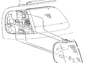
To replace the battery: 1. Twist a thin coin between the two halves of the transmitter near
45
Controls and features
the key ring. DO NOT TAKE THE FRONT PART OF THE TRANSMITTER APART. 2. Place the positive (+) side of new battery in the same orientation. Refer to the diagram inside the transmitter unit. 3. Snap the two halves back together.
Replacing lost transmitters
Take all your vehicle’s transmitters to your dealer for reprogramming if: • a transmitter is lost or • you want to purchase additional transmitters (up to four may be programmed).
To reprogram the transmitters, place the key in the ignition and switch from OFF to ON five times in rapid succession (within 10
seconds). After doors lock/unlock, press any button on all transmitters (up to four). When completed, switch the ignition to OFF. All transmitters must be programmed at the same time.Reprogramming transmitters To reprogram all transmitters, place the key in the ignition and switch from OFF to ON eight times in a row (within 10 seconds). After doors lock/unlock, press any button on all transmitters (up to
46
Controls and features
four). When completed, switch the ignition to OFF. All transmitters must be reprogrammed at the same time.
Illuminated entry The interior lamps illuminate when the remote entry system is used to unlock the door(s) or sound the personal alarm. The system automatically turns off after 25 seconds or when the ignition is turned to the START or ACC position. The dome lamp switch (if equipped) must not be set to the OFF position for the illuminated entry system to operate. The inside lights will not turn off if: • they have been turned on with • any door is open. Battery saver will shut off the interior lamps 40 minutes after the last door is closed.
the dimmer control or
47
Seating and safety restraints
SEATING
Full bench seat (if equipped) • Lift the release bar to move the seat forward or backward. Ensure that the seat is relatched into place. • Push down the release lever to
quickly fold the seatback forward.
60/40 split bench seat (if equipped) • Lift the release bar to move the seat forward or backward. Ensure the seat is relatched into place. • Pull the seatback handle up to • Push down the release lever located on the back of the seat to quickly fold the seatback forward.
recline the seat.
48
Seating and safety restraints
Captain’s chair (if equipped) • Lift the release bar to move the seat forward or rearward. Make sure that the seat is relatched into place. • Pull the seatback handle up to • Push the release lever down to
recline the seat.
quickly fold the seatback forward.
Adjusting the front power seat (if equipped)
Never adjust the driver’s seat or seatback when the
vehicle is moving.
Do not pile cargo higher than the seatbacks to
avoid injuring people in a collision or sudden stop.
Always drive and ride with your seatback upright and the lap belt snug and low across the hips.
49
Seating and safety restraints
Press to raise or lower the front portion of the seat cushion.
Press to raise or lower the rear portion of the seat cushion.
Press the control to move the seat forward, backward, up or down.
Using the manual lumbar support
Turn the lumbar support control counterclockwise to increase firmness. Turn the lumbar support control clockwise to increase softness.
50
Seating and safety restraints
60/40 Split Rear Seat (if equipped)
cushions.
When folded down, the rear seats provide a “load floor” for additional storage space. To fold down the rear seats: • Pull the straps to lower the seat • Store the center safety belt in the opening on the seat back. When returning the seats to their normal position: • Clear the load floor before • Make sure the seat cushion is • Remove the center safety belt
folding the seat up.
latched into place.
from its stowed position.
Check to assure that 60/40
Split rear seat cushion islatched by pulling up and forward on lap belt buckles.
SAFETY RESTRAINTS
Safety restraints precautions
Always drive and ride with your seatback upright and the lap belt snug and low across the hips.
51
Seating and safety restraints
To prevent the risk of injury, make sure children
sit where they can be properly restrained.
Never let a passenger hold a child on his or her lap
while the vehicle is moving. The passenger cannot protect the child from injury in a collision.
All occupants of the vehicle, including the
driver, should always wear their safety belts.
It is extremely dangerous to ride in a cargo area,
inside or outside of a vehicle. In a collision, people riding in these areas are more likely to be seriously injured or killed. Do not allow people to ride in any area of your vehicle that is not equipped with seats and safety belts. Be sure everyone in your vehicle is in a seat and using a safety belt properly.
52
Seating and safety restraints
Each seating position in your vehicle has a specific
safety belt assembly which is made up of one buckle and one tongue that are designed to be used as a pair. 1) Use the shoulder belt on the outside shoulder only. Never wear the shoulder belt under the arm. 2) Never swing it around your neck over the inside shoulder. 3) Never use a single belt for more than one person.
Combination lap and shoulder belts
1. To fasten, insert the tongue into the slot in the buckle.
2. To unfasten, push the red release button and remove the tongue from the buckle.
The front and rear outboard safety restraints in the vehicle are
53
Seating and safety restraints
combination lap and shoulder belts. The front and rear seat passenger outboard safety belts have two types of locking modes described below:
Vehicle sensitive mode The vehicle sensitive mode is the normal retractor mode, allowing free shoulder belt length adjustment to your movements and locking in response to vehicle movement. For example, if the driver brakes suddenly or turns a corner sharply, or the vehicle receives an impact of 8 km/h (5
mph) or more, the combination safety belts will lock to help reduce forward movement of the driver and passengers. The front seat belt system can also be made to lock manually by quickly pulling on the shoulder belt. Rear seat belts (if equipped) cannot be made to lock up by pulling quickly on the belt.Automatic locking mode In this mode, the shoulder belt is automatically pre-locked. The belt will still retract to remove any slack in the shoulder belt. The automatic locking mode is not available on the driver safety belt. Whentousetheautomatic lockingmode • When a tight lap/shoulder fit is
desired.
54
Seating and safety restraints
• Anytime a child safety seat is installed in the vehicle. Refer to Safety Restraints for Children or Safety Seats for Children later in this chapter.
Howtousetheautomatic lockingmode • Buckle the combination lap and
shoulder belt.
• Grasp the shoulder portion and pull downward until the entire belt is extracted.
• Allow the belt to retract. As the
belt retracts, you will hear a clicking sound. This indicates the safety belt is now in the automatic locking mode.
55
Seating and safety restraints
Howtodisengagetheautomatic lockingmode Disconnect the combination lap/shoulder belt and allow it to retract completely to disengage the automatic locking mode and activate the vehicle sensitive (emergency) locking mode.
Front safety belt height adjustment
Your vehicle has safety belt height adjustments for the driver and front passenger. Adjust the height of the shoulder belt so the belt rests across the middle of your shoulder. To lower the shoulder belt height, push the button and slide the height control down. To raise the height of the shoulder belt, slide the height adjuster up. Pull down on the height adjustment assembly to make sure it is locked in place.
Position the shoulder belt height adjuster so that the
belt rests across the middle of your shoulder. Failure to adjust the safety belt properly could reduce the effectiveness of the safety belt and increase the risk of injury in a collision.
Lap belts Adjustingthelapbelt The lap belt does not adjust automatically. Adjust to fit snugly
56
Seating and safety restraints
and as low as possible around your hips. Do not wear the lap belt around your waist.
Insert the tongue into the correct buckle. To lengthen the belt, turn the tongue at a right angle to the belt and pull across your lap until it reaches the buckle. To tighten the belt, pull the loose end of the belt through the tongue until it fits snugly across the hips.
Shorten and fasten the belt when not in use.
Safety belt extension assembly If the safety belt assembly is too short, even when fully extended, 20 cm (8 inches) can be added to the safety belt assembly by adding a safety belt extension assembly (part number 611C22). Safety belt extension assemblies can be obtained from your dealer at no cost. Use only extensions manufactured by the same supplier as the safety
57
Seating and safety restraints
belt. Manufacturer identification is located at the end of the webbing on the label. Also, use the safety belt extension only if the safety belt is too short for you when fully extended. Do not use extensions to change the fit of the shoulder belt across the torso.
Safety belt warning light and indicator chime The seat belt warning light illuminates in the instrument cluster and a chime sounds to remind the occupants to fasten their safety belts.
Conditions of operation
If... The driver’s safety belt is not buckled before the ignition key is turned to ON...
The driver’s safety belt is buckled while the indicator light is illuminated and the warning chime is sounding... The driver’s safety belt is buckled before the ignition key is turned to ON...
Then... The safety belt warning light illuminates for one to two minutes and the warning chime sounds for four to eight seconds. The safety belt warning light turns off.
The safety belt warning light remains off.
Safety belt maintenance Check the safety belt systems periodically to make sure they work properly and are not damaged. Check the safety belts to make sure there are no nicks, wears or cuts. All safety belt
58
Seating and safety restraints
assemblies, including retractors, buckles, front seat belt buckle assemblies (slide bar)(if equipped), shoulder belt height adjusters (if equipped), child safety seat tether bracket assemblies (if equipped), and attaching hardware, should be inspected after a collision. Ford recommends that all safety belt assemblies used in vehicles involved in a collision be replaced. However, if the collision was minor and a qualified technician finds that the belts do not show damage and continue to operate properly, they do not need to be replaced. Safety belt assemblies not in use during a collision should also be inspected and replaced if either damage or improper operation is noted.
Failure to replace the safety belt assembly under the above conditions could result in severe personal injuries in the event of a collision.
Refer to Cleaning and maintaining the safety belts in the Maintenance and care section.
59
Seating and safety restraints
AIR BAG SUPPLEMENTAL RESTRAINT SYSTEM (SRS)
LOW FUEL
DOOR AJAR
BRAKE
18
PULL FOR FOG
PANEL
DIM
ON
OFF
40
6030
40
20
20
10
0 0
MPH
50 60
80
100
70
0 0 0 0 0 0
120
80
THEFT
140
90
160
km/h
100
CHECK SUSP
P R N 2 1
RPMx1000
ABS
CHECK ENGINE
RES
SET
ACCEL
COAST
SRS
VOL - PUSH ON
O V E R D R I V E
AM FM
BASS
TREB
FM1
ST
BAL
FADE AUTO SET
REW
LO
4H
4L
A4WD
SEEK
TUNE DISCS
SCAN
EJ
w DOLBY B NR
TAPE CD
FF
SIDE 1-2
COMP
SHUFFLE
FLOOR
OFF
PANEL
PANEL & FLOOR
FLR& DEF DEF
HI
COOL
WARM
Important supplemental restraint system (SRS) precautions
The supplemental restraint system is designed to: • work with the safety belt to protect the driver and right front passenger • reduce certain upper body
injuries
Failure to follow these instructions will affect the performance of the safety belts and increase the risk of personal injury.
60
Seating and safety restraints
The right front passenger air bag is not designed to restrain occupants in the center front seating position.
All occupants of the vehicle including the driver
should always wear their safety belts even when air bag SRS is provided.
Do not place objects or mount equipment on or near the air bag cover on the steering wheel or in front seat areas that may come into contact with a deploying air bag. Failure to follow this instruction may increase the risk of personal injury in the event of a collision.
Do not attempt to service, repair, or modify the Air
Bag Supplemental Restraint System or its fuses. See your Ford or Lincoln-Mercury dealer.
Children and air bags For additional important safety information, read all information on safety restraints in this guide. Children should always wear their safety belts. Failure to follow these instructions may increase the risk of injury in a collision.
61
Before driving
Introduction
Instrumentation
Controls and features
Seating and safety restraints
Starting and driving
Starting
Driving
Roadside emergencies
Servicing
Maintenance and care
Capacities and specifications
Reporting safety defects
Index
Contents
17
48
76
83
131
152
205
215
216
All rights reserved. Reproduction by any means, electronic or mechanical including photocopying, recording or by any information storage and retrieval system or translation in whole or part is not permitted without written authorization from Ford Motor Company.
Copyright r 1997 Ford Motor Company
Elemental Chlorine Free
Introduction
ICONS
Indicates a warning. Read the following section on Warnings for a full explanation.
Indicates vehicle information related to recycling and other environmental concerns will follow. Correct vehicle usage and the authorized disposal of waste cleaning and lubrication materials are significant steps towards protecting the environment.
WARNINGS Warnings provide information which may reduce the risk of personal injury and prevent possible damage to others, your vehicle and its equipment.
BREAKING-IN YOUR VEHICLE There are no particular breaking-in rules for your vehicle. During the first 1 600 km (1 000 miles) of driving, vary speeds frequently. This is necessary to give the moving parts a chance to break in. If possible, you should avoid full use of the brakes for the first 1 600 km (1 000 miles).
INFORMATION ABOUT THIS GUIDE The information found in this guide was in effect at the time of printing. Ford may change the
contents without notice and without incurring obligation.
SPECIAL NOTICES
Using your vehicle with a snowplow For more information and guidelines for using your vehicle with a snowplow, refer to the Driving chapter.
Using your vehicle as an ambulance
Do not use this vehicle as an ambulance.
Your vehicle is not equipped with the Ford Ambulance Preparation package.
Notice to owners of utility type vehicles Before you drive your vehicle, please read this Owner’s Guide carefully. Your vehicle is not a passenger car. As with other vehicles of this type, failure to operate this vehicle correctly may result in loss of control or an accident. Be sure to read Driving off road in the Driving chapter as well as the “Four Wheeling” supplement included with 4WD and utility type vehicles.
Introduction
Instrumentation
Instrument cluster
(pg. 6)
Speed control
(pg. 28)
LOW FUEL
+ -
18
+ -
40 50 60
80
•100
•
60
•0 0 0 0
0 5
•
70
12080
90•140
•
0 0 0
100
30
40•20
20•km/h
10
ON
OFF
SRS
Headlamp control
(pg. 17)
Turn signal and wiper/washer
control (pg. 34)
Instrument panel dimmer switch
(pg. 18)
THEFT
0 RPMx1000
CHECK ENGINE
ABS
4 X 4
RES
SET
ACCEL
COAST
Driver side air
bag
(pg. 60)
Instrumentation
Electronic sound system; refer to
Audio Guide
(pg. 19)
Gearshift (includes
overdrive button)
(pg. 88)
VOL-PUSH ON
FM 1
FM 1
AM FM
BASS TREB
ST
BAL
FADE AUTO SET
SEEK TUNE DISCS
REW
LO
SCAN
EJ
DOLBY 8 NR
TAPE CD
FF
SIDE 1-2
COMP
SHUFFLE
FLOOR
OFF
PANEL & FLOOR
PANEL
FLR& DEF DEF
PASSENGER AIRBAG
ON
OFF
OFF
HI
COOL
WARM
Climate control
systems (pg. 20)
4WD Control*
(pg. 102)
Passenger air bag deactivate switch
(pg. 65)
Auxiliary power
point
(pg. 19)
Instrumentation
WARNING LIGHTS AND CHIMES
Standard instrument cluster
LOW FUEL
DOOR AJAR
BRAKE
+ -
UNLEADED FUEL ONLY
CHECK ENGINE
40
6050 60
80
100
0 0 0 0 0
30
4020
1020 km/h
0 0 0 0
MPH P R N 2 1
70
12080
90140
160
100Optional instrument cluster
LOW FUEL
DOOR AJAR
BRAKE
+ -
18
40
6050 60
80
100
0 0 0 0 0
30
4020
1020 km/h
0 0 0 0
MPH P R N 2 1
70
12080
90140
160
100Low fuel
Illuminates when the fuel level is low. The lamp will also illuminate when the ignition key is turned to ON and the engine is off.
Check engine
Your vehicle is equipped with a computer that monitors the engine’s emission control system. This system is commonly known as
18
FUEL RESET
ABS
CHECK SUSP
LOW RANGE
4 X 4
THEFT FUEL DOOR
RPM 1000
ABS
CHECK SUSP
CHECK ENGINE
FUEL RESET
LOW RANGE
4 X 4
LOW FUEL
CHECK ENGINE
the On Board Diagnostics System (OBD II). This OBD II system protects the environment by ensuring that your vehicle continues to meet government emission standards. The OBD II system also assists the service technician in properly servicing your vehicle. The Check Engine indicator light illuminates when the ignition is first turned to the ON position to check the bulb. If it comes on after the engine is started, one of the engine’s emission control systems may be malfunctioning. The light may illuminate without a driveability concern being noted. The vehicle will usually be drivable and will not require towing. Whatyoushoulddoifthe checkenginelightilluminates Light turns on solid: This means that the OBD II system has detected a malfunction. Temporary malfunctions may cause your Check Engine light to illuminate. Examples are: 1. The vehicle has run out of fuel. (The engine may misfire or run poorly.) 2. Poor fuel quality or water in the fuel. 3. The fuel cap may not have been properly installed and securely tightened. These temporary malfunctions can be corrected by filling the fuel tank
Instrumentation
Instrumentation
with good quality fuel and/or properly installing and securely tightening the gas cap. After three driving cycles without these or any other temporary malfunctions present, the Check Engine light should turn off. (A driving cycle consists of a cold engine startup followed by mixed city/highway driving.) No additional vehicle service is required. If the Check Engine light remains on, have your vehicle serviced at the first available opportunity. Light is blinking: Engine misfire is occurring which could damage your catalytic converter. You should drive in a moderate fashion (avoid heavy acceleration and deceleration) and have your vehicle serviced at the first available opportunity.
Under engine misfire conditions, excessive exhaust temperatures could damage the catalytic converter, the fuel system, interior floor coverings or other vehicle components, possibly causing a fire.
Air bag readiness
Momentarily illuminates when the ignition is turned ON. If the light fails to illuminate, continues to flash or remains on, have the system serviced immediately.
Safety belt
Momentarily illuminates when the ignition is turned ON to remind you to fasten your safety belts. For more information, refer to the Seating and safety restraints chapter.
Brake system warning
Momentarily illuminates when the ignition is turned on and the engine is off. Also illuminates when the parking brake is engaged. Illumination after releasing the parking brake indicates low brake fluid level.
Anti-lock brake system (ABS)
Momentarily illuminates when the ignition is turned on and the engine is off. If the light remains on, continues to flash or fails to illuminate, have the system serviced immediately.
Turn signal
Illuminates when the left or right turn signal or the hazard lights are turned on. If one or both of the indicators stay on continuously or flash faster, check for a burned-out turn signal bulb. Refer to Exterior bulbs in the Maintenance and care chapter.
Instrumentation
BRAKE
ABS
THEFT
Instrumentation
High beams
Illuminates when the high beam headlamps are turned on.
Anti-theft system (if equipped)
Refer to Perimeter alarm system in the Controls and features chapter.
Charging system
Momentarily illuminates when the ignition is turned ON and the engine is off. The light also illuminates when the battery is not charging properly, requiring electrical system service.
Oil pressure/Engine coolant
very high
This light will come on when the key is in the ON position and the: • engine coolant temperature is • engine oil pressure is low The light serves as a notice that a system needs your attention and to check the engine coolant temperature gauge and the engine oil pressure gauge. Refer to Engine coolant temperature gauge and Engine
10
oil pressure gauge in this chapter for more information.
Four wheel drive low (if equipped)
Illuminates when four-wheel drive low is selected.
Four wheel drive indicator (if equipped)
Instrumentation
LOW RANGE
Illuminates when 4x4 range is selected.
4x4
Check air suspension (if equipped)
Illuminates briefly when the ignition is turned to the ON position and the engine is OFF. The light also illuminates when the air suspension system requires servicing. For information, refer to Air suspension system in the Driving chapter.
Door ajar
Illuminates when the ignition switch is in the ON or START position and any door is open.
CHECK SUSP
DOOR AJAR
11
FUEL RESET
Instrumentation
Fuel reset
Illuminates when the ignition key is turned to the ON position and the fuel pump shut-off switch has been triggered. For more information, refer to Fuel pump shut-off switch in the Roadside emergencies chapter.
Safety belt warning chime Chimes to remind you to fasten your safety belts. For information on the safety belt warning chime, refer to the Seating and safety restraints chapter.
Supplemental restraint system (SRS) warning chime For information on the SRS warning chime, refer to the Seating and safety restraints chapter.
Key-in-ignition warning chime Sounds when the key is left in the ignition in the OFF/LOCK or ACC position and either front door is opened.
Headlamps on warning chime Sounds when the headlamps or parking lamps are on, the ignition is off (and the key is not in the ignition) and either front door is opened.
12
GAUGES
Standard instrument cluster gauges
LOW FUEL
DOOR AJAR
BRAKE
+ -
UNLEADED FUEL ONLY
CHECK ENGINE
40
6050 60
80
100
0 0 0 0 0
30
4020
1020 km/h
0 0 0 0
MPH P R N 2 1
70
12080
90140
160
100Optional instrument cluster gauges
LOW FUEL
DOOR AJAR
BRAKE
+ -
18
40
6050 60
80
100
0 0 0 0 0
30
4020
1020 km/h
0 0 0 0
MPH P R N 2 1
70
12080
90140
160
100Fuel gauge
Displays approximately how much fuel is in the fuel tank (when the key is in the ON position). The fuel gauge may vary slightly when the vehicle is in motion. The ignition should be in the OFF position while the vehicle is being refueled. When the gauge first indicates empty, there is a small amount of reserve fuel in the tank.
Instrumentation
18
FUEL RESET
ABS
CHECK SUSP
LOW RANGE
4 X 4
THEFT
FUEL DOOR
RPM 1000
ABS
CHECK ENGINE
FUEL RESET
4 X 4
CHECK SUSP
LOW RANGE
13
Instrumentation
When refueling the vehicle from empty indication, the amount of fuel that can be added will be less than the advertised capacity due to the reserve fuel.
Speedometer
Indicates the current vehicle speed.
Engine coolant temperature gauge
Indicates the temperature of the engine coolant. At normal operating temperature, the needle remains within the normal area (the area between the “H” and “C”). If it enters the red section, the engine is overheating. Stop the vehicle, switch off the ignition and let the engine cool. Refer to Engine coolant in the Maintenance and care chapter.
Never remove the coolant recovery cap while the
engine is running or hot.
This gauge indicates the temperature of the engine coolant, not the coolant level. If the coolant
14
40
6050 60
80
100
0 0 0 0 0
70
12080
90140
160
10030
4020
1020 km/h
0 0 0 0
MPH
is not at its proper level or mixture, the gauge indication will not be accurate.
Odometer
Registers the total kilometers (miles) of the vehicle.
Trip odometer
Registers the kilometers (miles) of individual journeys. To reset, depress the control.
Tachometer
Indicates the engine speed in revolutions per minute. Driving with your tachometer pointer continuously at the top of the scale may damage the engine.
Instrumentation
40
6050 60
80
100
0 0 0 0 0
30
4020 km/h
0 0 0 0
MPH
20
1070
12080
90140
160
10040
6050 60
80
100
0 0 0 0 0
30
4020 km/h
0 0 0 0
MPH
20
1070
12080
90140
160
100FUEL DOOR
RPM 1000
15
18
Instrumentation
Battery voltage gauge
This gauge shows the battery voltage when the ignition is in the ON position. If the pointer moves and stays outside the normal operating range (as indicated), have the vehicle’s electrical system checked as soon as possible.
Engine oil pressure gauge
This shows the engine oil pressure in the system. Sufficient pressure exists as long as the needle remains in the normal range (the area between the “H” and “L”). If the gauge indicates low pressure, switch off the engine immediately. Check the oil level. Add oil if needed (refer to Checking and adding engine oil in the Maintenance and care chapter). If the oil level is correct, have your vehicle checked at your dealership or by a qualified technician.
16
Controls and features
HEADLAMP CONTROL
Rotate the headlamp control to the desired position:
PULL FOR FOG
— OFF. — Parking lamps on.
— Headlamps on.
Foglamp control (if equipped)
The headlamp control also operates the foglamps. The foglamps can be turned on only when the headlamps are in the
position.
Pull headlamp control towards you to turn foglamps on. The foglamp indicator light (located to the right of the control) will illuminate.
Daytime running light (Canadian vehicles only) The daytime running light system turns the headlamps on, with a reduced light output, when: • the vehicle is running • the parking brake is released • the headlamp system is in the
OFF position
PULL FOR FOG
17
Controls and features
The Daytime Running Light (DRL) system will
not illuminate the tail lamps and parking lamps. Turn on your headlamps at dusk. Failure to do so may result in a collision.
PANEL DIMMER CONTROL
Use to adjust the brightness of the instrument panel. • Rotate up to brighten. • Rotate down to dim.
AUTOLAMP CONTROL (IF EQUIPPED)
The autolamp system provides light sensitive automatic on-off control of the exterior lights normally controlled by the headlamp control. The autolamp system also keeps the lights on for a preselected period of time after the ignition switch is turned to OFF. • To turn autolamps on, rotate the control up. The preselected time lapse is adjustable up to approximately three minutes by continuing to rotate the control upward. • To turn autolamps off, rotate the
control down until it clicks.
18
• A small LED illuminates next to the autolamp control to indicate that the headlamps have been turned on by the autolamps. • Foglamps are not controlled by the autolamps. In order to turn on the foglamps, you must turn the lamp switch to the
position and pull for fog.
4WD CONTROL (IF EQUIPPED)
This control operates the 4WD. Refer to Four-wheel drive (4WD) operation in the Driving chapter for more information.
AUXILIARY POWER POINT
The auxiliary power point is located on the instrument panel. Do not plug optional electrical accessories into the cigarette lighter. Use the powerpoint.
AUDIO SYSTEM Refer to the “Audio Guide” for instructions on how to operate the audio system.
Controls and features
4H
2H
4L
19
Controls and features
CLIMATE CONTROL SYSTEM
Heater only system (if equipped)
LO
HI
PANEL
OFF
PANEL & FLOOR
FLOOR
FLR & DEF
DEF
COOL
WARM
Fanspeedcontrol
Controls the volume of air circulated in the vehicle.
Temperaturecontrolknob
Controls the temperature of the airflow inside the vehicle. On heater-only systems, the air cannot be cooled below the outside temperature. Modeselectorcontrol
Controls the direction of the airflow to the inside of the vehicle.
LO
HI
COOL
WARM
PANEL
OFF
PANEL & FLOOR
FLOOR
FLR & DEF
DEF
• PANEL-Distributes outside air through the instrument panel registers.
• OFF-Outside air is shut out and
the fan will not operate.
20
• PANEL & FLOOR-Distributes outside air through the instrument panel registers and the floor ducts. • FLOOR-Allows for maximum heating. Distributes outside air through the floor ducts.
• FLOOR & DEF-Distributes outside air through the floor ducts and the windshield defroster ducts.
• DEF
-Distributes outside air through the windshield defroster ducts. It can be used to clear ice or fog from the windshield.
Operatingtips • In humid weather, select
before driving. This will
help to prevent your windshield from fogging. After a few minutes, select any desired position. • To prevent humidity buildup inside the vehicle, don’t drive with the climate control system in the OFF position.
• Don’t put objects under the
front seat that will interfere with the airflow to the back seats (if equipped).
Controls and features
21
Controls and features
• Remove any snow, ice or leaves from the air intake area (at the bottom of the windshield under the hood).
• When placing objects on top of your instrument panel, be careful to not place them over the defroster outlets. These objects can block airflow and reduce your ability to see through your windshield. Also, avoid placing small objects on top of your instrument panel. These objects can fall down into the defroster outlets and block airflow and possibly damage your climate control system.
Manual heating and air conditioning system (if equipped)
LO
HI
PANEL
OFF
PANEL & FLOOR
A/C
MAX A/C
FLOOR
FLR