- 2016 Cadillac CTS Owners Manuals
- Cadillac CTS Owners Manuals
- 2009 Cadillac CTS Owners Manuals
- Cadillac CTS Owners Manuals
- 2006 Cadillac CTS Owners Manuals
- Cadillac CTS Owners Manuals
- 2008 Cadillac CTS Owners Manuals
- Cadillac CTS Owners Manuals
- 2013 Cadillac CTS Owners Manuals
- Cadillac CTS Owners Manuals
- 2003 Cadillac CTS Owners Manuals
- Cadillac CTS Owners Manuals
- 2011 Cadillac CTS Owners Manuals
- Cadillac CTS Owners Manuals
- 2014 Cadillac CTS Owners Manuals
- Cadillac CTS Owners Manuals
- 2010 Cadillac CTS Owners Manuals
- Cadillac CTS Owners Manuals
- 2015 Cadillac CTS Owners Manuals
- Cadillac CTS Owners Manuals
- 2005 Cadillac CTS Owners Manuals
- Cadillac CTS Owners Manuals
- 2004 Cadillac CTS Owners Manuals
- Cadillac CTS Owners Manuals
- 2012 Cadillac CTS Owners Manuals
- Cadillac CTS Owners Manuals
- 2007 Cadillac CTS Owners Manuals
- Cadillac CTS Owners Manuals
- Download PDF Manual
-
Position the release button on the buckle, so that the safety belt could be quickly unbuckled if necessary.
5. Pull the rest of the shoulder belt all the way out of the retractor to set the lock.
You will be using the lap-shoulder belt to secure the child restraint in this position. Follow the instructions that came with the child restraint. 1. Move the seat as far back as it
will go before securing the forward-facing child restraint. When the passenger sensing system has turned off the front passenger frontal airbag, the off indicator on the passenger airbag status indicator should light and stay lit when the vehicle is started. See Passenger Airbag Status Indicator on page 4‑22.
2. Put the child restraint on
the seat.
3. Pick up the latch plate, and run the lap and shoulder portions of the vehicle's safety belt through or around the restraint. The child restraint instructions will show you how.
If the airbag is off, the off indicator in the passenger airbag status indicator will come on and stay on when the vehicle is started. If a child restraint has been installed and the on indicator is lit, see “If the On Indicator is Lit for a Child Restraint†under Passenger Sensing System on page 2‑35 for more information. To remove the child restraint, unbuckle the vehicle safety belt and let it return to the stowed position.
2-62
Seats and Restraints
6. To tighten the belt, push down on the child restraint, pull the shoulder portion of the belt to tighten the lap portion of the belt and feed the shoulder belt back into the retractor. When installing a forward-facing child restraint, it may be helpful to use your knee to push down on the child restraint as you tighten the belt. 7. Push and pull the child restraint in different directions to be sure it is secure.
Storage
Storage Compartments
Instrument Panel Storage . . . . 3-1
Glove Box . . . . . . . . . . . . . . . . . . . . 3-1
Cupholders . . . . . . . . . . . . . . . . . . . 3-1
Center Console Storage . . . . . . 3-1Additional Storage Features
Cargo Cover . . . . . . . . . . . . . . . . . . 3-2
Cargo Management System(Wagon Only) . . . . . . . . . . . . . . . . 3-3
Cargo Net (Wagon) . . . . . . . . . . . 3-4
Convenience Net (Sedan) . . . . . 3-6Roof Rack System
Roof Rack System (Wagon) . . . 3-6
Storage Compartments
Instrument Panel Storage Your vehicle has a storage area located below the climate control systems. To access, push on the cover.
Glove Box To open, press the button. Use the key to lock and unlock. The glove box has a shelf that can be removed by pulling it out.
Storage
3-1
Cupholders The vehicle has cupholders located in front of the center console. Push down on the cover to open. There are also cupholders in the rear center armrest. Pull the armrest down to use.
Center Console Storage Your vehicle has a center console with an upper and lower storage area. To access the upper storage area, lift the driver side lever on the front of the console and lift the cover. To access the lower storage area, lift the passenger side lever on the center console. There is an additional storage area behind the center console. To access, push the cover.
3-2
Storage
Additional Storage Features
Cargo Cover The cargo cover can be used to cover items in the cargo area of the vehicle.
3. Make sure the cartridge is
properly installed by pulling it slightly up, it should be firmly fitted.
4. Grasp the handle and unroll the
cover. Latch the posts into the sockets on the inside of the vehicle to secure it.
To remove the cargo cover, do the following: 1. Release the cover from the latch
posts and carefully roll it back up.
2. Pull the handle (A) back and
remove it from the pin (B) on the trim panel. Repeat this on the other side.
To install the cargo cover: 1. Hold the cartridge so that the
pull out shade faces backwards.
2. Align the cartridge over the
pin (B) on both sides. Press the cartridge down and turn it slightly forward until it clicks.
Storage
3-3
{ WARNING
Cargo Management System (Wagon Only)
An improperly stored cargo cover could be thrown about the vehicle during a collision or sudden maneuver. Someone could be injured. If the cover is removed, always store it in the proper storage location. When it is replaced, always be sure that it is securely reattached.
The cover can be opened to two positions to allow access to the storage area. Some items may be stored in the cargo area when the cover is closed.
Press on the bottom of load floor handle assembly to lift the top on the handle. Pull up on the handle to open the cargo management system.
3-4
Storage
D-Ring Sliders There are four D-Ring sliders that move along rails on both sides of the cargo management area. These can be used as tie-downs when storing cargo.
Installing D-Ring Sliders
The loop of the D-Ring slider must be facing inward towards the storage area and the ring must be in the up position for proper usage. Push the button to move the D-Ring slider either towards the front or the rear of the vehicle. The rings can be locked into various positions along the rail.
To install the D-Ring slider (A), insert it into the channel (B) located in the middle of each rail.
Cargo Net (Wagon) { WARNING
Do not stack items higher than the upper end of the cargo net or hang anything from the net. Avoid items that have sharp edges or that apply excessive force to the net. If items are not properly stored, damage to the net could occur and items can be thrown about the vehicle. You or other could be injured. Always store items behind the net.
For vehicles equipped with a cargo net, it can be used to store light loads, keeping them from falling over or being thrown into the cabin during heavy braking. The net should not be overloaded or used to store heavy loads.
Storage
3-5
2. There are four tether positions
for the lower hook straps. In the front position, the seat backs should be down for the net to properly hold items.
1. There are four installation
openings in the roof, two located in front of and two behind the rear seats. Insert the top corners of the cargo net into the large opening in the roof and secure by sliding them into the small opening.
3. Mount the cargo net to the rear seat tethers located on the front of the bottom cushions.
4. The net can also be mounted to
the tethers on the back of the rear seats when the seats are upright.
3-6
Storage
5. Pull on the straps to tighten
the net. Put light loads behind the net to keep them from falling over or being thrown into the cabin during heavy braking. The net should not be overloaded or used to store heavy loads.
Convenience Net (Sedan) Your vehicle may have a convenience net in the rear of the vehicle. Put small loads behind the net. It can also be positioned into an envelope style to hold smaller items. The net is not for heavier loads. Store items as far forward as you can.
Roof Rack System
Roof Rack System (Wagon)
{ WARNING If something is carried on top of the vehicle that is longer or wider than the roof rack — like paneling, plywood, or a mattress — the wind can catch it while the vehicle is being driven. The item being carried could be violently torn off, and this could cause a collision, and damage the vehicle. Never carry something longer or wider than the roof rack on top of the vehicle unless using a GM Certified accessory carrier.
For vehicles with a roof rack, the rack can be used to load items. For roof racks that do not have crossrails included, GM Certified crossrails can be purchased as an accessory. See your dealer/retailer for additional information. Notice: Loading cargo on the roof rack that weighs more than 75 kg (165 lbs) or hangs over the rear or sides of the vehicle may damage the vehicle. Load cargo so that it rests evenly between the crossrails, making sure to fasten cargo securely.
To prevent damage or loss of cargo when driving, check to make sure crossrails and cargo are securely fastened. Loading cargo on the roof rack will make the vehicle’s center of gravity higher. Avoid high speeds, sudden starts, sharp turns, sudden braking or abrupt maneuvers, otherwise it may result in loss of control. If driving for a long distance, on rough roads, or at high speeds, occasionally stop the vehicle to make sure the cargo remains in its place. Do not exceed the maximum vehicle capacity when loading the vehicle. For more information on vehicle capacity and loading, see Vehicle Load Limits on page 8‑12.
Storage
3-7
Installation of Crossrails
A. Crossrails B. Crossrail End C. Siderail Cover 1. Siderail covers (C) must be
removed for installing the crossrails (A).
2. To remove siderail covers, start
at the back of the vehicle and pull straight up.
3-8
Storage
3. Store the siderail covers in a
place where it can be laid flat. Do not stack any items on top of the cover.
6. The crossrail supports are
labeled with an arrow that needs to point toward the front of the vehicle. When the lever on the crossrail support is in the down position a pin (A) will be visible on the bottom of the assembly. To install the crossrail support, move the lever into the forward upper position. The pin (A) should no longer be visible.
8.
7. Locate the forward or rearward most cut-out (A) in the siderail channel. Insert both crossrail ends into the cut-outs, making sure the arrows on the crossrail ends are pointed towards the front of the vehicle.
4.
Identify front and rear crossrail by the size of the crossrail support.
5. The front crossrail support (A) is
smaller than the rear crossrail support (B).
10. Move the levers on both
crossrail supports to the down position. Slide the crossrail assembly back and forth until the crossrail pin engages.
11. Push back and forth again to
make sure the pins have engaged into the slots. Make sure both crossrails are locked into the same hole position on each side of the vehicle.
Storage
3-9
Removing the Crossrails 1. Start with either crossrail
assembly, slide both levers into the upper most position, moving the lever from the rear to the front of the vehicle.
2. Slide the crossrail assembly until
it is in the cut-out area or the siderail channel.
3. Remove the crossrail from the
vehicle.
4. Repeat steps 1–3 for the other
crossrail assembly.
5. Reinstall the siderail covers
making sure they are fully seated in the siderail channel.
9. Levers must still be in the
forward up position. For front crossbar, slide the crossrail assembly (A) forward until the crossrail end is past the channel cut-out area (B). For rear crossbar, slide the crossrail assembly (A) rearward until the entire crossrail support is in first position to the rear of the channel cut-out area (B).
3-10
Storage
2 NOTES
Instruments and Controls
4-1
Instruments and Controls
Instrument Panel Overview
Instrument Panel Overview . . . . 4-4
Controls
Steering Wheel Adjustment . . . 4-6
Steering Wheel Controls . . . . . . 4-7
Horn . . . . . . . . . . . . . . . . . . . . . . . . . . 4-7
Windshield Wiper/Washer . . . . . 4-8
Rear Window Wiper/Washer . . . . . . . . . . . . . . . . . . . . . . 4-9
Headlamp Washer . . . . . . . . . . . 4-10
Compass . . . . . . . . . . . . . . . . . . . . 4-11
Clock . . . . . . . . . . . . . . . . . . . . . . . . 4-12
Power Outlets . . . . . . . . . . . . . . . 4-12
Cigarette Lighter . . . . . . . . . . . . . 4-13
Ashtrays . . . . . . . . . . . . . . . . . . . . . 4-14Warning Lights, Gages, and Indicators
Warning Lights, Gages, and
Indicators . . . . . . . . . . . . . . . . . . 4-14
Instrument Cluster . . . . . . . . . . . 4-15
Speedometer . . . . . . . . . . . . . . . . 4-17
Odometer . . . . . . . . . . . . . . . . . . . . 4-17
Trip Odometer . . . . . . . . . . . . . . . 4-17
Tachometer . . . . . . . . . . . . . . . . . . 4-17
Fuel Gage . . . . . . . . . . . . . . . . . . . 4-17
Boost Gage . . . . . . . . . . . . . . . . . . 4-18
Engine Speed Limiter . . . . . . . . 4-19
Engine Oil Pressure Gage . . . 4-19
Engine CoolantTemperature Gage . . . . . . . . . 4-20
Safety Belt Reminders . . . . . . . 4-21
Airbag Readiness Light . . . . . . 4-21
Passenger Airbag StatusIndicator . . . . . . . . . . . . . . . . . . . . 4-22
Charging System Light . . . . . . 4-23Malfunction
Indicator Lamp . . . . . . . . . . . . . 4-23
Brake System Warning
Light . . . . . . . . . . . . . . . . . . . . . . . 4-26
Antilock Brake System (ABS)
Warning Light . . . . . . . . . . . . . . 4-27
Up-Shift Light . . . . . . . . . . . . . . . . 4-28
Traction Control System(TCS)/StabiliTrak® Light . . . . 4-28
Engine Coolant Temperature
Warning Light . . . . . . . . . . . . . . 4-29
Tire Pressure Light . . . . . . . . . . 4-29
Engine Oil Pressure Light . . . . 4-30
Security Light . . . . . . . . . . . . . . . . 4-30
High-Beam on Light . . . . . . . . . 4-30
Fog Lamp Light . . . . . . . . . . . . . . 4-31
Lamps on Reminder . . . . . . . . . 4-31
Cruise Control Light . . . . . . . . . 4-31Information Displays
Driver Information
Center (DIC) . . . . . . . . . . . . . . . 4-31
4-2
Instruments and Controls
Vehicle Messages
Vehicle Messages . . . . . . . . . . . 4-36
Battery Voltage and ChargingMessages . . . . . . . . . . . . . . . . . . 4-37
Brake System Messages . . . . 4-38
Compass Messages . . . . . . . . . 4-39
Cruise Control Messages . . . . 4-39
Door Ajar Messages . . . . . . . . . 4-39
Engine Cooling SystemMessages . . . . . . . . . . . . . . . . . . 4-40
Engine Oil Messages . . . . . . . . 4-40
Engine Power Messages . . . . 4-41
Fuel System Messages . . . . . . 4-42Key and Lock Messages . . . . . 4-42
Lamp Messages . . . . . . . . . . . . . 4-44
Object Detection SystemMessages . . . . . . . . . . . . . . . . . . 4-45
Ride Control System
Messages . . . . . . . . . . . . . . . . . . 4-45
Airbag System Messages . . . . 4-48
Anti-Theft Alarm SystemMessages . . . . . . . . . . . . . . . . . . 4-48
Service Vehicle Messages . . . 4-48
Tire Messages . . . . . . . . . . . . . . . 4-48
Transmission Messages . . . . . 4-49
Vehicle Speed Messages . . . . 4-50
Washer Fluid Messages . . . . . 4-50Vehicle Personalization
Vehicle Personalization . . . . . . 4-51
OnStar® System
OnStar® System . . . . . . . . . . . . . 4-59
Universal Remote System
Universal Remote System . . . 4-61
Universal Remote SystemProgramming . . . . . . . . . . . . . . . 4-61
Universal Remote System
Operation . . . . . . . . . . . . . . . . . . 4-65
Instruments and Controls
4-3
2 NOTES
4-4
Instruments and Controls
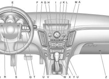
Instrument Panel Overview
CTS Shown, CTS-V Similar
Instruments and Controls
4-5
A. Air Vents on page 7‑6. B. Driver Information Center (DIC)
C.
on page 4‑31 . Instrument Panel Illumination Control on page 5‑5.
D. Turn and Lane-Change Signals
E.
on page 5‑4 . Instrument Cluster on page 4‑15 .
F. Windshield Wiper/Washer on
page 4‑8 . Rear Window Wiper/Washer on page 4‑9
(If Equipped).G. Navigation Button (If Equipped). See Navigation System Manual.
H. Traction Control System (TCS) on page 8‑37 . Magnetic Ride Control on page 8‑40 (CTS-V Model Only).
I. Clock on page 4‑12. J. Passenger Sensing System on
page 2‑35 .
K. Hazard Warning Flashers on
R. Steering Wheel Adjustment on
page 5‑4 .
page 4‑6 .
L. Navigation Display Brightness
Control (If Equipped). See Navigation System Manual. M. AM-FM Radio on page 6‑9
(Base Audio System) or Navigation/Radio System (If Equipped). See Navigation System Manual.
N. Parking Brake (Manual) on
page 8‑34 or Parking Brake (Electric) on page 8‑35.
O. Hood on page 9‑5. P. Cruise Control on page 8‑41 . Traction Control System (TCS) Disable Button (CTS-V Model Only). See Traction Control System (TCS) on page 8‑37.
Q. Tap Shift Controls (CTS-V Model
Only). See Automatic Transmission on page 8‑26.
S. Horn on page 4‑7. T. Steering Wheel Controls on
page 4‑7 .
U. Heated and Ventilated Front
Seats on page 2‑9.
V. Dual Automatic Climate Control
System on page 7‑1.
W. Parking Brake (Manual) on
page 8‑34 or Parking Brake (Electric) on page 8‑35.
X. Shift Lever. See Automatic
Transmission on page 8‑26 or Manual Transmission on page 8‑30 . Instrument Panel Storage on page 3‑1 . Power Outlets on page 4‑12 .
Y.
Z. Glove Box on page 3‑1 .
4-6
Instruments and Controls
Controls
Steering Wheel Adjustment A tilt and telescope wheel lets the steering wheel be adjusted. Do not adjust the steering wheel while driving.
Power Tilt Wheel
The tilt and telescope lever is on the left side of the steering column. To tilt and telescope the steering wheel, pull the lever down. Then move the steering wheel up or down or backward or forward into a comfortable position. Pull the lever up to lock the steering wheel in place.
For vehicles with this feature, the power tilt wheel control is on the left side of the steering column. To operate the power tilt feature, push the control up or down to tilt the steering wheel up or down. Push the control forward or rearward to move the steering wheel toward the front or rear of the vehicle.
Steering Wheel Controls
Some audio steering wheel controls could differ depending on the vehicle's options. Controls that can be adjusted at the steering wheel may include: SRCE (Source): Press to switch between the radio AM, FM, XM (if equipped), CD, HDD (if equipped), auxiliary input jack, DVD (if equipped), and USB (if equipped).
Instruments and Controls
4-7
y / c z (Previous/Next): Press to go to the previous or next radio station stored as a favorite, or the previous or next track of a CD. Press to interact with the Bluetooth® system. See Bluetooth on page 6‑37 for more information.
+ e − e (Volume): Press to increase or to decrease the volume. b g (Mute/Speech Recognition/ Push to Talk): Press and release to silence the vehicle speakers only. The audio of the wireless and wired headphones, if the vehicle has these features, does not mute. Press and release b g again, to turn the sound on.
For vehicles with a navigation system, press and hold g for two seconds to initiate speech recognition. See “Speech Recognition†in the Navigation System manual for more information.
For vehicles without a navigation system, press and hold g for two seconds to interact with OnStar® or Bluetooth. See the OnStar® System on page 4‑59 , or Bluetooth on page 6‑37 for more information about these features. For vehicles with a navigation system, OnStar, or Bluetooth, press and hold g for two seconds and say “hands free†to interact with OnStar or Bluetooth. See the OnStar® System on page 4‑59 , or Bluetooth on page 6‑37 for more information about these features.
Horn Press near the horn symbols or press on the steering wheel pad to sound the horn.
4-8
Instruments and Controls
Windshield Wiper/Washer
Sedan Model shown
Wagon Model shown
Clear snow and ice from the wiper blades before using them. If frozen to the windshield, carefully loosen or thaw them. Damaged wiper blades should be replaced. For more information, see Wiper Blade Replacement on page 9‑33. Heavy snow or ice can overload the wiper motor. A circuit breaker will stop the motor until it cools down.
Wiper Arm Assembly Protection When using an automatic car wash, move the windshield wiper lever to the OFF position. This disables the windshield wipes and/or rear wipers, if equipped. The wiper operations return to normal when the transmission is no longer in N (Neutral) or the vehicle speed has increased.
The windshield wiper lever is on the right side of the steering column. Move the windshield wiper lever to select the wiper speed. 7 (Mist): Single wipe, briefly move the lever down and release. Several wipes, hold the lever down. T (Off): Turns the wipers off. & (Adjustable Interval Wipes): For a delayed wiping cycle. Turn the adjustable interval wiper band to set the frequency of wipes. 6 (Adjustable Interval Wiper Band): Turn the band up for more frequent wipes or down for less frequent wipes. 1 : Slow wipes. 2 : Fast wipes. If the windshield wipers are in use for about six seconds while you are driving, the exterior lamps come on automatically if the exterior lamp control is in AUTO. See “Wiper Activated Headlamps†for more information.
Instruments and Controls
4-9
Windshield Washer
{ WARNING
In freezing weather, do not use your washer until the windshield is warmed. Otherwise the washer fluid can form ice on the windshield, blocking your vision.
Sedan Model K (Washer Fluid): Press the button with this symbol, on the end of the windshield washer lever, to wash the windshield. The washer fluid sprays onto the windshield and the wipers run for a few cycles to clear the windshield. Press and hold K for more wash cycles. Wagon Model Pull the lever toward you to spray washer fluid on the windshield. The spray continues until the lever is released. The wipers will run a few times.
Washer Fluid Low Add Fluid displays on the Driver Information Center (DIC) when the washer fluid is low. See Driver Information Center (DIC) on page 4‑31. See Washer Fluid on page 9‑25 for information on filling the windshield washer fluid reservoir. If the headlamps are on while the windshield is being washed, the headlamp washers, if the vehicle has them, will also turn on. See “Headlamp Washer†following for more information. Wiper Activated Headlamps This feature activates the headlamps and parking lamps after the windshield wipers have been in use for about six seconds. For this feature to work, the exterior lamp control must be in AUTO. The wiper-activated headlamps immediately turn off, when the ignition is turned to LOCK/OFF or the windshield wiper control is turned off.
Rear Window Wiper/Washer For vehicles with a rear window wiper/washer, the controls are on the end of the windshield wiper lever.
Press the upper or lower portion of the button to control the rear wiper and rear wiper delay. The system turns off when the button is returned to the middle position.
4-10
Instruments and Controls
Z (Rear Wiper Delay Short): Sets a five second delay between wipes. 5 (Rear Wiper Delay Long): Sets a ten second delay between wipes. = (Rear Washer): Push the windshield wiper lever forward to spray washer fluid on the rear window. The lever returns to its starting position when released. The windshield washer reservoir is used for the windshield and the rear window. Check the fluid level in the reservoir if either washer is not working. See Washer Fluid on page 9‑25 .
Headlamp Washer For vehicles with headlamp washers they clear debris from the headlamp lenses.
Press the washer button at the end of the windshield wiper lever, to wash the headlamps. Both the headlamps and the windshield will be washed. After the first wash, the headlamps will not be washed until the fifth press of the windshield washer button. The headlamps must be on to be washed. If the headlamps are off, only the windshield will be washed when the washer button is pressed. If the washer fluid is low, the headlamp washers will not work. See Windshield Wiper/Washer on page 4‑8 for more information.
{ WARNING
The headlamp washers are beneath the headlamps.
In freezing weather, do not use your washer until the windshield is warmed. Otherwise the washer fluid can form ice on the windshield, blocking your vision.
Instruments and Controls
4-11
Compass The vehicle may have a compass in the Driver Information Center (DIC).
Compass Zone The zone is set to zone eight. If you do not live in zone eight or drive out of the area, the variance needs to be changed to the appropriate zone. To adjust for compass variance, use the following procedure:
Compass Variance (Zone) Procedure 1. Do not set the compass zone
when the vehicle is moving. On an automatic transmission vehicle, only set it when the vehicle is in P (Park). On a manual transmission vehicle, only set it when the vehicle is stopped. Press the vehicle information button until Press To Change Compass Zone displays.
2. Find the vehicle's current
location and variance zone number on the map. Zones 1 through 15 are available.
3. Press the set/reset button to scroll through and select the appropriate variance zone.
4. Press the trip/fuel button until
the vehicle heading, for example, N for North, is displayed in the DIC.
5. Calibrate the compass. See
“Compass Calibration Procedure†following.
Compass Calibration The compass can be manually calibrated. Only calibrate the compass in a magnetically clean and safe location, such as an open parking lot, where driving the vehicle in circles is not a danger. It is suggested to calibrate away from tall buildings, utility wires, manhole covers, or other industrial structures, if possible. If CAL appears in the DIC display, the compass should be calibrated. If the DIC display does not show a heading, for example, N for North, or the heading does not change after making turns, there may be a strong magnetic field interfering with the compass. Interference may be caused by a magnetic antenna mount, magnetic note pad holder, or any other magnetic item. Turn off the vehicle, move the magnetic item, then turn on the vehicle and calibrate the compass.
4-12
Instruments and Controls
To calibrate the compass, use the following procedure:
Compass Calibration Procedure 1. Before calibrating the compass, check that the compass is set to the correct variance zone. See “Compass Variance (Zone) Procedure†earlier in this section. Do not operate any switches such as window, sunroof, climate controls, seats, etc. during the calibration procedure.
2. Press the vehicle information button until Press To Calibrate Compass displays.
3. Press the set/reset button to start the compass calibration.
4. The DIC will display Calibrating
Drive In Circles. Drive the vehicle in tight circles at less than 8 km/h (5 mph) to complete the calibration. The DIC will display Calibration Complete for a few seconds when the calibration is complete. The DIC display will then return to Press To Calibrate Compass.
Clock The analog clock is located on the instrument panel above the radio. The clock is not connected with any other vehicle system and runs by itself. To adjust the clock: 1. Locate the adjustment buttons
directly below the clock face.
2. Push and hold the right
adjustment button to move the clock hands forward or the left adjustment button to make the clock hands go backward.
Holding either button down will cause the clock to advance faster. Release the button before the desired time is reached.
3. Push and release either button
to adjust the time by one minute increments until the desired time is reached.
Power Outlets Accessory power outlets can be used to connect auxiliary electrical equipment, such as a cellular telephone. There are three accessory power outlets. There is an outlet located in the front storage area below the climate control system, one inside the center console storage bin, and one on the rear of the center console. For CTS Wagon model only, there is an additional accessory power outlet located near the rear cargo net.
Instruments and Controls
4-13
Notice: Adding any electrical equipment to the vehicle can damage it or keep other components from working as they should. The repairs would not be covered by the vehicle warranty. Do not use equipment exceeding maximum amperage rating of 20 amperes. Check with your dealer/retailer before adding electrical equipment. Notice: Improper use of the power outlet can cause damage not covered by the vehicle warranty. Do not hang any type of accessory or accessory bracket from the plug because the power outlets are designed for accessory power plugs only.
Cigarette Lighter The vehicle may have a cigarette lighter. To use the lighter, push it in all the way and let go. When it is ready, it will pop back out by itself. Notice: Holding a cigarette lighter in while it is heating does not let the lighter back away from the heating element when it is hot. Damage from overheating can occur to the lighter or heating element, or a fuse could be blown. Do not hold a cigarette lighter in while it is heating.
To use an outlet, remove the protective cap. When not in use, always cover the outlet with the protective cap. The accessory power outlet is operational at all times. Notice: If electrical devices are left plugged into a power outlet, the battery may drain causing the vehicle not to start or damage to the battery. This would not be covered by the vehicle warranty. Always unplug all electrical devices when turning off the vehicle. Certain electrical accessories may not be compatible with the accessory power outlet and could result in blown vehicle or adapter fuses. If you experience a problem see your dealer/retailer for additional information on accessory power outlets.
4-14
Instruments and Controls
When one of the warning lights comes on and stays on while driving, or when one of the gages shows there may be a problem, check the section that explains what to do. Follow this manual's advice. Waiting to do repairs can be costly and even dangerous.
Warning Lights, Gages, and Indicators Warning lights come on when there could be a problem with a vehicle function. Some warning lights come on briefly when the engine is started to indicate they are working. Gages can indicate when there could be a problem with a vehicle function. Often gages and warning lights work together to indicate a problem with the vehicle.
Ashtrays The vehicle may have two removable ashtrays. One ashtray can be placed into the instrument panel storage compartment and the other into the center console rear compartment. To empty the ashtrays, hold on to the edges of the bin and pull straight out. To reinstall, push the tray back into place. Notice: If papers, pins, or other flammable items are put in the ashtray, hot cigarettes or other smoking materials could ignite them and possibly damage the vehicle. Never put flammable items in the ashtray.
Instrument Cluster
Instruments and Controls
4-15
United States Automatic Transmission Cluster Shown, Canada and Manual Similar
4-16
Instruments and Controls
United States V-Series Automatic Transmission Cluster Shown, Canada and Manual Similar
Instruments and Controls
4-17
Speedometer The speedometer shows the vehicle's speed in both kilometers per hour (km/h) and miles per hour (mph).
Odometer The odometer shows how far the vehicle has been driven, in either kilometers or miles. If this vehicle has to have a new odometer installed, the new one may read the correct mileage. This is because the vehicle computer has stored the mileage in memory.
Trip Odometer The trip odometer can record the number of miles or kilometers traveled for up to two trips. The trip odometer is part of the Driver Information Center (DIC), for more information see Driver Information Center (DIC) on page 4‑31 .
For vehicles that have the navigation system, see your Navigation System manual for more information.
Tachometer The tachometer displays the engine speed in revolutions per minute (rpm). Notice: If the engine is operated with the tachometer in the shaded warning area, the vehicle could be damaged, and the damages would not be covered by the vehicle warranty. Do not operate the engine with the tachometer in the shaded warning area. The CTS-V tachometer has tracer lights that follow the movement of the tachometer indicator. The tracer lights also flash when it is time to up-shift to avoid the engine speed limit. See Automatic Transmission on page 8‑26 or Manual Transmission on page 8‑30 for more information.
Fuel Gage
When the ignition is on, the fuel gage tells you about how much fuel you have left in your tank. An arrow on the fuel gage indicates the side of the vehicle the fuel door is on. When the indicator nears empty, the low fuel light comes on. There is still a little fuel left in the vehicle, but the fuel tank should be filled soon.
4-18
Instruments and Controls
The Fuel Level Low message appears in the Driver Information Center (DIC) and a single chime sounds. See Fuel System Messages on page 4‑42 for more information. Here are four things that some owners ask about. None of these show a problem with your fuel gage: . At the service station, the fuel
pump shuts off before the gage reads full. It takes a little more or less fuel to fill up than the gage indicated. For example, the gage may have indicated the tank was half full, but it actually took a little more or less than half the tank's capacity to fill the tank.
The gage moves a little while turning a corner or speeding up. The gage takes a few seconds to stabilize after the ignition is turned on, and will go back to empty when the ignition is turned off.
Boost Gage
Canada
For the CTS-V, this gage is located in the instrument panel cluster. This gage indicates positive manifold pressure which is the induction air pressure level in the intake manifold before it enters the combustion chamber. This gage reads zero under light throttle before boost is generated. This gage automatically resets to zero every time the engine is started.
United States
Engine Speed Limiter This feature prevents the engine speed from reaching an unsafe level. If the level is too high, the throttle closes or limits the fuel supply until the engine speed returns to a safe level. Throttle operation and fuel supply returns to normal when engine speed is lowered. For the CTS-V, the tachometer tracer lights flashes prior to reaching engine speed limit. The tracer lights also flash on automatic transmission vehicles while in the DSC or Tap Shift modes.
Instruments and Controls
4-19
Engine Oil Pressure Gage
United States
Canada
For vehicles with an engine oil pressure gage. It shows the engine oil pressure in psi (pounds per square inch) when the engine is running. Canadian vehicles indicate pressure in kPa (kilopascals). Oil pressure may vary with engine speed, outside temperature and oil viscosity, but if readings are outside the normal operating range, the oil pressure light will come on. See Engine Oil Pressure Light on page 4‑30 for more information.
4-20
Instruments and Controls
Engine Coolant Temperature Gage
United States
Canada
This gage shows the engine coolant temperature. If the engine coolant overheats the engine coolant temperature warning light will come on. See Engine Coolant Temperature Warning Light on page 4‑29 and Engine Overheating on page 9‑23 for more information.
A reading outside the normal operating range may be caused by a dangerously low oil level or some other problem causing low oil pressure. Oil should be checked as soon as possible. See Oil Pressure Low Stop Engine under Driver Information Center (DIC) on page 4‑31 and Engine Oil on page 9‑10 .
{ WARNING
Do not keep driving if the oil pressure is low. The engine can become so hot that it catches fire. Someone could be burned. Check the oil as soon as possible and have the vehicle serviced.
Notice: Lack of proper engine oil maintenance can damage the engine. The repairs would not be covered by the vehicle warranty. Always follow the maintenance schedule in this manual for changing engine oil.
Instruments and Controls
4-21
Safety Belt Reminders
Driver Safety Belt Reminder Light There is a driver safety belt reminder light on the instrument panel cluster.
Passenger Safety Belt Reminder Light
When the engine is started this light and the chime comes on and stays on for several seconds to remind the passenger to fasten their safety belt. The light also begins to flash. This cycle repeats if the passenger remains unbuckled and the vehicle is moving. If the passenger safety belt is buckled, neither the chime nor the light comes on.
When the engine is started this light and a chime come on and stay on for several seconds to remind drivers to fasten their safety belts. The light also begins to flash. This cycle repeats if the driver remains unbuckled and the vehicle is moving. If the driver safety belt is already buckled, neither the light nor chime come on.
The front passenger safety belt warning light and chime may turn on if an object is put on the seat such as a briefcase, handbag, grocery bag, laptop or other electronic device. To turn off the warning light and or chime, remove the object from the seat or buckle the safety belt.
Airbag Readiness Light This light shows if there is an electrical problem. The system check includes the airbag sensor, the pretensioners, the airbag modules, the wiring and the crash sensing and diagnostic module. For more information on the airbag system, see Airbag System on page 2‑27 .
4-22
Instruments and Controls
The airbag readiness light comes on and stays on for several seconds when the vehicle is started. Then the light goes out.
{ WARNING
If the airbag readiness light stays on after the vehicle is started or comes on while driving, it means the airbag system might not be working properly. The airbags in the vehicle might not inflate in a crash, or they could even inflate without a crash. To help avoid injury, have the vehicle serviced right away.
Passenger Airbag Status Indicator The vehicle has the passenger sensing system. See Passenger Sensing System on page 2‑35 for important safety information. The instrument panel has a passenger airbag status indicator.
United States
Canada
When the vehicle is started, the passenger airbag status indicator will light the words ON and OFF, or the symbols for on and off, for several seconds as a system check. If the vehicle has remote start, and it is being used to start the vehicle from a distance, you may not see the system check. Then, after several more seconds, the status indicator will light either ON or OFF, or either the on or off symbol, to let you know the status of the right front passenger frontal airbag. If the word ON or the on symbol is lit on the passenger airbag status indicator, it means that the right front passenger frontal airbag is enabled (may inflate). If the word OFF or the off symbol is lit on the passenger airbag status indicator, it means that the passenger sensing system has turned off the right front passenger frontal airbag.
If, after several seconds, both status indicator lights remain on, or if there are no lights at all, there may be a problem with the lights or the passenger sensing system. See your dealer/retailer for service.
{ WARNING
If the airbag readiness light ever comes on and stays on, it means that something may be wrong with the airbag system. To help avoid injury to yourself or others, have the vehicle serviced right away. See Airbag Readiness Light on page 4‑21 for more information, including important safety information.
Instruments and Controls
4-23
Charging System Light
The charging system light comes on briefly when the ignition is turned on but the engine is not running, as a check to show the light is working. It should go out when the engine is started. If the light stays on, or comes on while driving, there may be a problem with the electrical charging system. Have it checked by your dealer/retailer. Driving while this light is on could drain the battery. When this light comes on, the Driver Information Center (DIC) also displays a message. See Battery Voltage and Charging Messages on page 4‑37.
If a short distance must be driven with the light on, be sure to turn off all accessories, such as the radio and air conditioner.
Malfunction Indicator Lamp A computer system called OBD II (On-Board Diagnostics-Second Generation) monitors operation of the fuel, ignition, and emission control systems. It ensures that emissions are at acceptable levels for the life of the vehicle, helping to produce a cleaner environment.
This light comes on when the ignition is on, but the engine is not running, as a check to show it is working. If it does not, have the vehicle serviced by your dealer/ retailer.
4-24
Instruments and Controls
If the check engine light comes on and stays on, while the engine is running, this indicates that there is an OBD II problem and service is required. Malfunctions often are indicated by the system before any problem is apparent. Being aware of the light can prevent more serious damage to the vehicle. This system assists the service technician in correctly diagnosing any malfunction. Notice: If the vehicle is continually driven with this light on, after a while, the emission controls might not work as well, the vehicle's fuel economy might not be as good, and the engine might not run as smoothly. This could lead to costly repairs that might not be covered by the vehicle warranty.
Notice: Modifications made to the engine, transmission, exhaust, intake, or fuel system of the vehicle or the replacement of the original tires with other than those of the same Tire Performance Criteria (TPC) can affect the vehicle's emission controls and can cause this light to come on. Modifications to these systems could lead to costly repairs not covered by the vehicle warranty. This could also result in a failure to pass a required Emission Inspection/ Maintenance test. See Accessories and Modifications on page 9‑3 . This light comes on during a malfunction in one of two ways: Light Flashing: A misfire condition has been detected. A misfire increases vehicle emissions and could damage the emission control system on the vehicle. Diagnosis and service might be required.
The following can prevent more serious damage to the vehicle: . Reduce vehicle speed. . Avoid hard accelerations. . Avoid steep uphill grades.
If towing a trailer, reduce the amount of cargo being hauled as soon as it is possible.
If the light continues to flash, when it is safe to do so, stop the vehicle. Find a safe place to park the vehicle. Turn the vehicle off, wait at least 10 seconds, and restart the engine. If the light is still flashing, follow the previous steps and see your dealer/retailer for service as soon as possible. Light On Steady: An emission control system malfunction has been detected on the vehicle. Diagnosis and service might be required.
Instruments and Controls
4-25
An emission system malfunction might be corrected. . Make sure the fuel cap is fully
installed. See Filling the Tank on page 8‑52 . The diagnostic system can determine if the fuel cap has been left off or improperly installed. A loose or missing fuel cap allows fuel to evaporate into the atmosphere. A few driving trips with the cap properly installed should turn the light off. If the vehicle has been driven through a deep puddle of water, the vehicle's electrical system might be wet. The condition is usually corrected when the electrical system dries out. A few driving trips should turn the light off.
. Make sure to fuel the vehicle
with quality fuel. Poor fuel quality causes the engine not to run as efficiently as designed and may cause: stalling after start-up, stalling when the vehicle is changed into gear, misfiring, hesitation on acceleration, or stumbling on acceleration. These conditions might go away once the engine is warmed up. If one or more of these conditions occurs, change the fuel brand used. It will require at least one full tank of the proper fuel to turn the light off. See Gasoline Specifications on page 8‑50 .
If none of the above have made the light turn off, your dealer/retailer can check the vehicle. The dealer/retailer has the proper test equipment and diagnostic tools to fix any mechanical or electrical problems that might have developed.
Emissions Inspection and Maintenance Programs Some state/provincial and local governments have or might begin programs to inspect the emission control equipment on the vehicle. Failure to pass this inspection could prevent getting a vehicle registration. Here are some things to know to help the vehicle pass an inspection:
The vehicle will not pass this inspection if the check engine light is on with the engine running, or if the ignition is placed in ON/RUN and the light is not on.
4-26
Instruments and Controls
The vehicle will not pass this inspection if the OBD II (on-board diagnostic) system determines that critical emission control systems have not been completely diagnosed by the system. The vehicle would be considered not ready for inspection. This can happen if the battery has recently been replaced or if the battery has run down. The diagnostic system is designed to evaluate critical emission control systems during normal driving. This can take several days of routine driving. If this has been done and the vehicle still does not pass the inspection for lack of OBD II system readiness, your dealer/retailer can prepare the vehicle for inspection.
Brake System Warning Light This vehicle's hydraulic brake system is divided into two parts. If one part is not working, the other part can still work and stop the vehicle. For good braking both parts need to be working well. If the warning light comes on, there is a brake problem. Have the brake system inspected right away.
United States
Canada
This light should come on briefly when the ignition is placed in ON/RUN. If it does not come on then, have it fixed so it will be ready to warn if there is a problem.
When the ignition is on, the brake system warning light will also come on when the parking brake is set. The light will flash or stay on if the parking brake is not fully released. If the light stays on after the parking brake is fully released there is a base brake problem.
{ CAUTION
The brake system might not be working properly if the brake system warning light is on. Driving with the brake system warning light on can lead to a crash. If the light is still on after the vehicle has been pulled off the road and carefully stopped, have the vehicle towed for service.
Instruments and Controls
4-27
For vehicles with the Electric Park Brake (EPB), this red brake warning light comes on when the park brake is applied. If the light continues flashing after the park brake is released, or while driving, there is a problem with the Electric Parking Brake system. If the light does not come on, or remains flashing, see you dealer/retailer.
does not come on then, have it fixed so it will be ready to warn if there is a problem. If this park brake light comes on there is a problem with a system on the vehicle that is causing the park brake system to work at a reduced level. The vehicle can still be driven, but should be taken to a dealer/ retailer See Brake Assist (Except CTS-V) on page 8‑37 for more information.
For vehicles with the Electric Park Brake (EPB), this park brake status light should come on briefly when ignition is placed in ON/RUN. If it
Antilock Brake System (ABS) Warning Light
For vehicles with the Antilock Brake System (ABS), this light comes on briefly when the engine is started. If the light does not come on, have it fixed so it will be ready to warn if there is a problem. If the ABS light stays on, turn the ignition off. If the light comes on while driving, stop as soon as it is safely possible and turn the ignition off. A chime may also sound when the light comes on steady.
4-28
Instruments and Controls
Then start the engine again to reset the system. If the ABS light stays on, or comes on again while driving, the vehicle needs service. If the regular brake system warning light is not on, the vehicle still has brakes, but not antilock brakes. If the regular brake system warning light is also on, the vehicle does not have antilock brakes and there is a problem with the regular brakes. See Brake System Warning Light on page 4‑26 . For vehicles with a Driver Information Center (DIC), see Driver Information Center (DIC) on page 4‑31 for all brake related DIC messages.
Up-Shift Light
Traction Control System (TCS)/StabiliTrak® Light
The vehicle may have an up-shift light, it shows when to shift to the next higher gear for best fuel economy. See Manual Transmission on page 8‑30 for more information. For the CTS-V, the tracer lights function as a performance up-shift light. These tracers flash to indicate when to shift to the next higher gear to avoid the engine speed limit. See Automatic Transmission on page 8‑26 or Manual Transmission on page 8‑30 for more information.
The Traction Control System (TCS)/StabiliTrak warning light should come on briefly when the engine is started. If it does not, have the vehicle serviced by your dealer/retailer. If the system is working normally the indicator light then goes off. If the light comes on or stays on while driving, there may be a problem with the TCS/StabiliTrak and the vehicle may need service. When this warning light is on, the system does not limit wheel spin. Adjust driving accordingly.
Instruments and Controls
4-29
See Traction Control System (TCS) on page 8‑37 and StabiliTrak System on page 8‑38 for more information.
Engine Coolant Temperature Warning Light
Stop the vehicle and turn off the engine to avoid damage to the engine. A warning chime sounds when this light is on. See Engine Overheating on page 9‑23 for more information.
Tire Pressure Light
The engine coolant temperature warning light comes on briefly when the engine is started. If it does not, have the vehicle serviced by your dealer/retailer. If the system is working normally the indicator light then goes off. If the light comes on and stays on while driving, the vehicle may have a problem with the cooling system.
For vehicles with a tire pressure monitoring system, this light comes on briefly when the engine is started. It provides information about tire pressures and the Tire Pressure Monitoring System.
When the Light is On Steady This indicates that one or more of the tires are significantly underinflated. A tire pressure message in the Driver Information Center (DIC), can accompany the light. See Tire Messages on page 4‑48 for more information. Stop as soon as possible, and inflate the tires to the pressure value shown on the tire loading information label. See Tire Pressure on page 9‑66 for more information.
When the Light Flashes First and Then is On Steady This indicates that there may be a problem with the Tire Pressure Monitor System. The light flashes for about a minute and stays on steady for the remainder of the ignition cycle. This sequence repeats with every ignition cycle. See Tire Pressure Monitor Operation on page 9‑69 for more information.
4-30
Instruments and Controls
Engine Oil Pressure Light
{ WARNING
Do not keep driving if the oil pressure is low. The engine can become so hot that it catches fire. Someone could be burned. Check the oil as soon as possible and have the vehicle serviced.
Notice: Lack of proper engine oil maintenance can damage the engine. The repairs would not be covered by the vehicle warranty. Always follow the maintenance schedule in this manual for changing engine oil.
Security Light
The oil pressure light should come on briefly as the engine is started. If it does not come on have the vehicle serviced by your dealer/ retailer. If the light comes on and stays on, it means that oil is not flowing through the engine properly. The vehicle could be low on oil and might have some other system problem. See your dealer/retailer.
This light flashes when the security system is activated. For more information, see Vehicle Security on page 1‑23.
High-Beam on Light
The high-beam on light comes on when the high-beam headlamps are in use. See Headlamp High/Low-Beam Changer on page 5‑2 for more information.
Fog Lamp Light
Cruise Control Light
Information Displays
Instruments and Controls
4-31
The fog lamp light comes on when the fog lamps are in use. The light goes out when the fog lamps are turned off. See Fog Lamps on page 5‑5 for more information.
Lamps on Reminder
This light comes on whenever the cruise control is set. The light goes out when the cruise control is turned off. See Cruise Control on page 8‑41 for more information.
This light comes on when the taillamps are on.
Driver Information Center (DIC) The Driver Information Center (DIC) gives you the status of many of your vehicle's systems. The DIC is also used to display warning/status messages. All messages appear in the DIC display located at the bottom of the instrument panel cluster. The DIC buttons are located on the instrument panel, next to the steering wheel. The DIC comes on when the ignition is on. After a short delay, the DIC displays the information that was last displayed before the engine was turned off. The top line of the DIC display shows the DIC information. The bottom line of the DIC display shows the compass. The compass displays in the trip/fuel menus and in some vehicle information menus.
4-32
Instruments and Controls
If a problem is detected, a warning message appears on the display. Take any message that appears on the display seriously and remember that clearing the message only makes the message disappear, and does not correct the problem. DIC Operation and Displays
The Driver Information Center (DIC) has different displays which can be accessed by pressing the DIC buttons located on the instrument panel, next to the steering wheel.
3 (Trip/Fuel): Press this button to scroll through the trip and fuel displays. See “Trip/Fuel Display Menu Items†following for more information on these displays. T (Vehicle Information): Press this button to scroll through the vehicle information displays. See “Vehicle Information Display Menu Items†following for more information on these displays. U (Customization): Press this button to scroll through each of the customization features. See Vehicle Personalization on page 4‑51 for more information on the customization features. V (Set/Reset): Press this button to reset certain DIC features and to acknowledge DIC warning messages and clear them from the DIC display.
y z (Menu Up/Down): Press this button to scroll up and down the menu items. Trip/Fuel Display Menu Items 3 (Trip/Fuel): The following display menu items can be displayed by pressing the trip/fuel button:
Odometer This display shows the distance the vehicle has been driven in either miles (mi) or kilometers (km).
Trip A or Trip B These displays show the current distance traveled since the last reset for each trip odometer in either miles (mi) or kilometers (km). Both odometers can be used at the same time. Each trip odometer can be reset to zero separately by pressing and holding the set/reset button for a few seconds while the desired trip odometer is displayed.
Fuel Range This display shows the approximate number of remaining miles (mi) or kilometers (km) you can drive without refilling the fuel tank. This estimate is based on the current driving conditions and changes if the driving conditions change. For example, if you are driving in traffic and making frequent stops, the display may read one number, but if you enter the freeway, the number may change even though you still have the same amount of fuel in the fuel tank. This is because different driving conditions produce different fuel economies. Generally, freeway driving produces better fuel economy than city driving. Once the range drops below about 30 miles (48 km) remaining, the display shows Low Range. If the vehicle is low on fuel, the Fuel Level Low message displays. See “Fuel Level Low†under Fuel System Messages on page 4‑42 for more information.
Instruments and Controls
4-33
AVG (Average) Economy This display shows the approximate average miles per gallon (mpg) or liters per 100 kilometers (L/100 km). This number is calculated based on the number of mpg (L/100 km) recorded since the last time this display was reset. To reset this display to zero, press the set/reset button.
Timer This display can be used like a stopwatch. You can record the time it takes to travel from one point to another. To access the timer, press the trip/fuel button until Timer 00:00:00 displays. To turn on the timer, press the set/reset button until the timer starts. To turn off the timer, press the set/reset button again. The timer stops and displays the end timing value.
To reset the timer to zero, press and hold the set/reset button after the timer has been stopped.
Inst (Instantaneous) Economy This display shows the current fuel economy in either miles per gallon (mpg) or liters per 100 kilometers (L/100 km). This number reflects only the fuel economy that the vehicle has right now and changes frequently as driving conditions change. Unlike average economy, this display cannot be reset.
AVG (Average) Speed This display shows the average speed of the vehicle in either miles per hour (mph) or kilometers per hour (km/h). This average is calculated based on the various vehicle speeds recorded since the last reset of this display. To reset this display to zero, press the set/reset button.
4-34
Instruments and Controls
Speedometer This display shows a digital speedometer in the DIC. The speed displays in either miles per hour (mph) or kilometers per hour (km/h). To change the units from English to metric, see “Units†later in this section.
Blank Display This display shows no information. Vehicle Information Display Menu Items T (Vehicle Information): The following display menu items can be displayed by pressing the vehicle information button:
Oil Life Remaining If the vehicle has this display, it shows the estimated oil life remaining. If you see 99% Oil Life Remaining on the display, that means that 99% of the current oil life remains.
When the oil life is depleted, the Change Engine Oil Soon message appears on the display. You should change the oil as soon as possible. In addition to the engine oil life system monitoring the oil life, additional maintenance is recommended in the Maintenance Schedule in this manual. See Scheduled Maintenance on page 10‑3 and Engine Oil on page 9‑10 . The Oil Life must be reset after each oil change. It does not reset itself. Avoid accidental resetting of the Oil Life system. It cannot be reset accurately until the next oil change. To reset the engine oil life system, See Engine Oil Life System on page 9‑12 . The display shows 100% when the system is reset.
Units This display allows you to select between English or Metric units of measurement. Once in this display, press the set/reset button to select between English or Metric units.
Parking Assist If the vehicle has the Ultrasonic Rear Parking Assist (URPA) system, this display allows the system to be turned on or off. Once in this display, press the set/reset button to select between On or Off. The URPA system automatically turns back on after each vehicle start. When the URPA system is turned off and the vehicle is shifted out of P (Park), the DIC displays the Parking Assist Off message as a reminder that the system has been turned off. See Object Detection System Messages on page 4‑45
and Ultrasonic Parking Assist on page 8‑44 for more information.Tire Pressure The pressure for each tire can be viewed in the DIC. The tire