- 2008 Volvo V70 Owners Manuals
- Volvo V70 Owners Manuals
- 2007 Volvo V70 Owners Manuals
- Volvo V70 Owners Manuals
- 2002 Volvo V70 Owners Manuals
- Volvo V70 Owners Manuals
- 2006 Volvo V70 Owners Manuals
- Volvo V70 Owners Manuals
- 2003 Volvo V70 Owners Manuals
- Volvo V70 Owners Manuals
- 2001 Volvo V70 Owners Manuals
- Volvo V70 Owners Manuals
- Download PDF Manual
-
1. The ignition switch must be turned to the "accessory" position (II) before programming the HomeLink® Universal Transceiver.
2. Begin by erasing all 3 factory default channels. Hold down the two outside buttons (buttons 1 and 3 in the illustration) on the HomeLink® Universal Transceiver for about 20 seconds, until HomeLink®'s indicator light begins to flash. Then release the buttons.
3. Hold your hand-held transmitter (garage door opener, for example) 2 to 5 in. (5 to 12 cm) away from the HomeLink® surface, keeping the indicator light in view. For placement questions, contact HomeLink® toll-free 1- 800-355-3515 (Internet: www.HomeLink.com).
4. Using two hands, push and hold both your hand-held transmitter's button and the transceiver button you wish to program. The indicator light will flash first slowly, then rapidly. Rapid flashing tells you the HomeLink® button has
been successfully programmed. Release both buttons.
5. If you are programming a rolling code-equipped device (e.g., garage door opener or entry door lock), refer to "Programming rolling codes" on the next page to complete the programming process.
Repeat steps 3 and 4 to program the other two transceiver buttons.
If, after several attempts, you are unable to successfully train the HomeLink® Universal Transceiver to learn your hand-held transmitter's signal, contact HomeLink® toll-free 1-800-355-3515 (Internet: www.HomeLink.com).
WARNING!
If you use HomeLink® to open a garage door or gate, be sure no one is near the gate or door while it is in motion. Do not use the HomeLink® Universal Transceiver with any garage door opener that lacks safety "stop" and
"reverse" features as required by federal safety standards. (This includes any garage door opener model manufactured before April 1, 1982) A garage door opener that cannot "detect" an object, signalling the door to "stop" and "reverse" does not meet current federal safety standards. Using a garage door opener without these features increases the risk of serious injury or death. For more information on this matter, call toll-free 1-800-355- 3515 (Internet: www.HomeLink.com).
pg. 168 HomeLink® Universal Transceiver (option)
NOTE - Canadian residents: During programming, your hand-held transmitter may automatically stop transmitting. To successfully train HomeLink®, continue to hold the HomeLink® button. At the same time, repeatedly press and hold your hand-held transmitter's button at two-second intervals until HomeLink® has learned your transmitter's code. The HomeLink® indicator light will flash first slowly, and then rapidly to indicate that the button has been successfully programmed.
Determining if your garage door uses a rolling code Determine, in one of the following ways, if your garage door uses a rolling code system and is manufactured after 1996:
Refer to the garage door opener owner's manual for verification. If your hand-held transmitter appears to program the HomeLink® Universal Transceiver but the programmed button
does not activate the garage door, your garage door opener may have a rolling code.
Press the programmed HomeLink® button. If the garage door opener has the rolling code feature, the HomeLink®
indicator light flashes rapidly and then glows steadily after approximately 2 seconds.
To train a rolling code garage door opener, follow these instructions after programming the desired transceiver button according to "Programming the transceiver." The help of a second person may make training easier.
1. Locate the training button on the garage door opener motor head unit. The location and color of the training button may vary. If you encounter difficulty, refer to the garage door opener owner's manual or call toll-free 1-800-355-3515
(Internet: www.HomeLink.com).2. Press the "training" button on the garage door opener motor head unit until the "training" light comes on.
3. Press and release the programmed HomeLink® button. Press and release the programmed HomeLink® button a second time to complete the training process. Some garage door openers may require you to do this procedure a third time to complete the training.
The programmed button on your HomeLink® Universal Transceiver should now operate your garage door opener. The
original hand-held transmitter can also be used, as desired, to operate the garage door.
The remaining two HomeLink® buttons can be programmed in the same way. In the event of any problems in programming the HomeLink® Universal Transceiver, call toll-free 1-800-355-3515 (Internet: www.HomeLink.com).
Operating the HomeLink® Universal Transceiver Once programmed, the HomeLink® Universal Transceiver can be used in place of your hand-held transmitters.
To operate, the key must be turned to the "accessory" position (II) or the engine must be running. Press the programmed HomeLink® button to activate the garage door, driveway gate, security lighting, home security system, etc.
Your original hand-held transmitters may, of course, be used at any time.
Erasing programmed buttons Individual buttons cannot be erased. To erase all three programmed buttons:
1. Turn the ignition key to the "accessory" position (II).
2. Hold down the two outside buttons on the HomeLink® Universal Transceiver for about 20 seconds, until HomeLink®'s indicator light begins to flash.
3. Release both buttons.
The HomeLink® buttons can be reprogrammed using the procedures described on the previous page.
(HomeLink® information continues on the next page)
pg. 169 HomeLink® Universal Transceiver (option)
Reprogramming a single HomeLink® button
1. Press and hold the desired HomeLink® button. Do not release the button until step 3 has been completed.
2. When the indicator light begins to flash slowly (after approximately 20 seconds), position your hand-held transmitter 2 to 5 in. (5 to 12 cm) away from the HomeLink® surface.
3. Press and hold the hand-held transmitter button. The HomeLink® indicator light will flash first slowly, then rapidly. When the indicator light flashes rapidly, release both buttons.
The previously programmed device has now been erased and the new device can be activated by pressing the HomeLink® button that has just been programmed. This procedure will not affect any other programmed HomeLink® buttons.
NOTE:
Retain the original transmitter(s) for future programming procedures (e.g., if you purchase a new car). For your own security, erase all programmed buttons on the HomeLink® Universal Transceiver when you sell your
car.
Metallic sun protection films should not be used on any windows in a car equipped with HomeLink® Universal
Transceiver. This could interfere with the transceiver's function.
Contents | Top of Page
2 0 0 3 VOLVO
V70
Chapter 8 - Maintenance/Servicing
pg. 115 Maintenance/Servicing
Fuses 116
Replacing bulbs 120
Paint touch up 126
Washing the car 127
Cleaning the upholstery 128
Maintenance service, Warranty 129
Fuel/emissions systems 130
Drive belt, Air pump system, Coolant 131
Emissions maintenance 132
Washer fluid reservoir, Hoisting the car 133
Opening the hood, Engine compartment 134
Engine oil 135
Power steering/Brake fluid reservoirs 137
Battery maintenance 138
Replacing wiper blades 140pg. 116 Fuses
Replacing fuses
If an electrical component fails to function, it is possible that a fuse has blown due to a temporary circuit overload.
Fuses are located in different places:
A - Relays/fuse box in the engine compartment B - Fuse box in the passenger compartment C - Relays/fuse box in the cargo area
A label on the inside of each cover indicates the amperage and the electrical components that are connected to each fuse.
The easiest way to see if a fuse is blown is to remove it. Pull the fuse straight out. If a fuse is difficult to remove, you will find a special fuse removal tool in the passenger compartment fuse box. From the side, examine the curved metal wire to see if it is broken. If so, put in a new fuse of the same color and amperage (written on the fuse). Spare fuses are stored in the fuse box in the passenger compartment. If fuses burn out repeatedly, have the electrical system inspected by an authorized Volvo retailer.
WARNING! Never use fuses with higher amperage that those stated on the following pages. Doing so could overload the car's electrical system.
pg. 117 Fuses in the engine compartment
Relays/fuses in the engine compartment
When replacing fuses, be sure to replace a blown fuse with a new one of the same color and amperage (written on the fuse). Fuse amperage is also indicated on the inside of the fuse box cover.
A - To open, press the plastic catches on the rear side of the fuse box cover and lift
Ordinary fuses
Amperage 25A 20A 15A 20A 10A 15A 10A 10A 15A 10A 20A 5A 25A 30A
Location 1 Accessories 2 Auxiliary lamps (option) 3 Vacuum pump 4 Oxygen sensors 5 Crankcase ventilation heater, solenoid valves 6 Mass airflow sensor, engine control module, injectors 7 Throttle module 8 AC compressor, accelerator pedal position sensor, E-box fan 9 Horn 10 Tailgate wiper 11 AC compressor, ignition coils 12 Brake light switch 13 Windshield wipers 14 ABS/STC/DSTC 15 - 16 Windshield washers, headlight wiper/washers (certain models) 15A 10A 17 Low beam, right 18 Low beam, left 10A 30A 19 ABS/STC/DSTC 15A 20 High beam, left 21 High beam, right 15A 25A 22 Starter motor 23 Engine control module 5A 24 -
pg. 118 Fuses in the passenger compartment
Fuse box in the passenger compartment
This fuse box is located at the far left side of the instrument panel. Extra fuses and the fuse removal tool are also stored here. When replacing a blown fuse, be sure to replace it with a new one of the same color and amperage (written on the fuse).
Location 1 Low beam headlights 2 High beam headlights 3 Power driver's seat 4 Power passenger's seat 5 - 6 - 7 Heated seat - front left (option) 8 Heated seat - front right (option) 9 ABS/STC/DSTC 10 - 11 - 12 Headlight wipers (certain models) 13 Electric socket 12 V 14 Power passenger's seat 15 Audio system, VNS 16 Audio system 17 Audio amplifier 18 Front fog lights 19 VNS display 20 - 21 Automatic transmission, shiftlock, extended D2 feed 22 Direction indicators 23 Headlight switch module, climate control system, onboard diagnostic connector, steering wheel lever modules 24 Relay for extended D1 feed: climate control system, power driver's seat, driver's info 25 Ignition switch, relay starter motor, SRS, engine control module 26 Climate control system blower 27 - 28 Electronic module - courtesy lighting 29 - 30 Left front/rear parking lights 31 Right front/rear parking lights, license plate lights 32 Central electrical module, vanity mirror lighting, power steering, glove compartment light, interior courtesy lighting
Amperage 15A 20A 30A 30A
15A 15A 5A
15A 15A 5A 5A 20A 30A 15A 10A
10A 20A 5A 10A 10A 30A
10A
7.5A 7.5A 10A
33 Fuel pump 34 Power sun roof 35 Central locking system, power windows - left door mirror 36 Central locking system, power windows - right door mirror 37 Rear power windows, power child safety 38 Alarm siren
* Please be aware that if this fuse is not intact, or if it is removed, the alarm will sound.
15A 15A 25A 25A 30A 5A
pg. 119 Fuses in the cargo area
Fuses in the cargo area
The fuses in the cargo area are located on the trim on the left-hand side. When replacing a blown fuse, be sure to replace it with a new one of the same color and amperage (written on the fuse).
Ordinary fuses
Amperage Location 10A 1 Rear electrical module, cargo area lighting 10A 2 Rear fog light 15A 3 Brake lights 4 Backup lights 10A 5 Rear window defroster, relay 15I - accessories 5A 6 Unlocking tailgate 10A 7 Auxiliary 12 volt socket in cargo area (option) 15A 20A 8 Central locking rear doors/fuel filler door 15A 9 Trailer (30 feed) 10 CD changer, VNS 10A 15A 11 Accessory control module (AEM) 12 Tailgate wiper 15A 13 Loudspeaker (subwoofer) cargo area - option 15A 7.5A 14 Brake lights 15 Trailer (15I feed) 20A 16 - 17 All Wheel Drive control module
7.5A
18 -
pg. 120 Replacing bulbs
Replacing high/low beam headlight bulbs
The headlight bulbs must be replaced from the engine compartment.
CAUTION:
Do not touch the glass on halogen bulbs with your fingers. Grease, oil or any other impurities can be carbonized onto
the bulb and cause damage to the reflector.
Be sure to use bulbs of the correct type and voltage.
To remove a defective low beam bulb:
Removing a defective bulb
Switch off all lights and turn the ignition switch to position 0. Open the hood. Remove the plastic cover over the bulb (1) by turning it counterclockwise. Remove the connector (2). Loosen the retaining spring (3) by first moving it to the right and then moving it down, out of the way. Pull out the defective bulb. Note the position of the guide lug on the base of the bulb (4).
To install a new low beam bulb (H7):
Installing a new bulb
Insert the new bulb, without touching the glass, with the guide lug upward (1). The bulb will only seat properly in
this position.
Move the retaining spring up and push it slightly to the left until it seats properly (2). Press the connector into place on the bulb (3). Reinstall the plastic cover and turn it clockwise until it is correctly in place (4). "TOP" must be upward.
NOTE: If the vertical aim of your headlights needs to be adjusted for any reason (e.g., towing a trailer for extended periods), this should be done by an authorized Volvo retailer.
pg. 121 Replacing bulbs
To remove and install a high beam bulb (HB3):
Switch off all lights and turn the ignition switch to position 0. Open the hood. Remove the cover by twisting it counterclockwise. Twist the bulb holder counterclockwise, pull it out and fit a new bulb. Note its position. Refit the bulb holder. It can only be fitted in one way. Screw the cover back on. The word TOP should be upwards.
Replacement of front parking light bulb
Switch off all lights and turn ignition key to position 0. Remove the low beam cover by twisting counterclockwise. Pull out the bulb and its socket. Replace bulb. Press the bulb and its socket back into place. Check that the new bulb lights. Screw the cover back into place, "TOP" should be upwards!
Changing the bulb in the turn signals at the front corners
Switch off all lights and turn ignition key to position 0. Pull out the bulb and its socket by twisting counterclockwise. Replace bulb. Press the bulb and its socket back into place. Check that the new bulb lights.
pg. 122 Replacing bulbs
Replacement of bulbs in backup light, rear parking lights and rear fog lights
Switch off all lights and turn the ignition switch to position 0. Open the access panel. Remove the sound insulation behind it. Twist the bulb holder counterclockwise and remove it. Press the bulb inward, twist it counterclockwise and extract it. Fit a new bulb. Fit the bulb holder in place and twist it clockwise.
Refit the sound insulation and put the access panel back in place.
Replacement of rear turn signal and brake light bulbs
Switch off all lights and turn the ignition switch to position 0. Using a screwdriver, carefully pry off the speaker grille. Pull out the red tab in the speaker. Then press on the black pin above the extracted red tab and twist out the speaker. Twist the bulb holder counter-clockwise, and withdraw it. Fit a new bulb. Fit the bulb holder in place and twist it clockwise. Refit the speaker and press in the red tab. Press the speaker grille back into position.
pg. 123 Replacing bulbs
Front fog lights (option)
CAUTION: Avoid touching the glass on the bulb with your fingers.
Switch off all lights and turn the ignition key to position 0. Turn the bulb holder slightly counterclockwise to release it. Replace the bulb. The shape of the base of the bulb corresponds to the shape of the bulb holder. Reinstall the bulb holder by turning it slightly clockwise. "TOP" on the holder should be upward.
Side direction indicator
Open the front door halfway. From the inside of the fender, push the lamp housing out. Turn the bulb holder 1/4 turn counterclockwise and pull it out from the lens. Remove the defective bulb by pulling it straight out. Insert a new bulb. Reinsert the bulb holder in the lens and press the entire unit back into place on the fender.
Door step courtesy lights
The door step courtesy lights are located under the dash on the driver's and passenger's sides. To replace a bulb:
Carefully insert a screwdriver and pry out the lens. Replace the defective bulb. Reinstall the lens.
pg. 124 Replacing bulbs
License plate lights
Switch off the ignition. Loosen the screws with a Torx screwdriver. Carefully pull out the lamp housing. Turn the bulb holder counterclockwise and pull it out. Pull out the defective bulb and insert a new one. Reinsert the bulb holder into the housing and turn it clockwise. Reinstall the housing and screw it in place.
Vanity mirror lights
Carefully insert a screwdriver and pry out the lens. Pry out the defective bulb and replace it. Carefully press the lower edge of lens onto the four tabs and press the upper edge of the lens into place.
Front courtesy lights
These bulbs may be difficult for you to replace yourself. We recommend that you let an authorized Volvo retailer replace these bulbs if necessary.
pg. 125 Replacing bulbs
Rear reading lights
These bulbs may be difficult for you to replace yourself. We recommend that you let an authorized Volvo retailer replace these bulbs if necessary.
NOTE: Other bulbs may be difficult for you to replace yourself. Let an authorized Volvo retailer replace these bulbs if necessary.
pg. 126 Paint touch up
Paint touch-up
Paint damage requires immediate attention to avoid rusting. Make it a habit to check the finish regularly - when washing the car for instance. Touch-up if necessary.
Paint repairs require special equipment and skill. Contact your Volvo retailer for any extensive damage.
Minor scratches can be repaired by using Volvo touch-up paint.
NOTE: When ordering touch-up paint from your Volvo retailer, use the paint code indicated on the model plate. The plate is located in the engine compartment.
Minor stone chips and scratches
Material: Primer - can Paint - touch-up bottle Brush
Masking tape
NOTE: When touching up the car, it should be clean and dry. The surface temperature should be above 60° F (15° C). Minor scratches on the surface
If the stone chip has not penetrated down to the metal and an undamaged layer of paint remains, the touch-up paint can be applied as soon as the spot has been cleaned.
Deep scratches
1. Place a strip of masking tape over the damaged surface. Pull the tape off so that any loose flakes of paint adhere to it.
2. Thoroughly mix the primer and apply it with a small brush. When the primer surface is dry, the paint can be applied using a brush. Mix the paint thoroughly; apply several thin paint coats and let dry after each application.
3. If there is a longer scratch, you may want to protect surrounding paint by masking it off.
pg. 127 Washing the car
Washing the car
The car should be washed at regular intervals since dirt, dust, insects and tar spots adhere to the paint and may cause
damage. It is particularly important to wash the car frequently in the wintertime to prevent corrosion, when salt has been used on the roads.
When washing the car, do not expose it to direct sunlight. Use lukewarm water to soften the dirt before you wash
with a sponge and plenty of water, to avoid scratching.
Bird droppings: Remove from paintwork as soon as possible. Otherwise the finish may be permanently damaged. A detergent can be used to facilitate the softening of dirt and oil. A water-soluble grease solvent may be used in cases of sticky dirt. However, use a wash place equipped with a
drainage separator.
Remove dirt from the drain holes in the doors and rocker panels. Dry the car with a clean chamois. Tar spots can be removed with kerosene or tar remover after the car has been washed. A stiff-bristle brush and lukewarm soapy water can be used to clean the wiper blades. Frequent cleaning improves
visibility considerably.
Wash off the dirt from the underside (wheel housings, fenders, etc.). In areas of high industrial fallout, more frequent washing is recommended.
CAUTION: During high pressure washing, the spray mouthpiece must never be closer to the vehicle than 13" (30 cm). Do not spray into the locks. Special sun roof cautions: - Always close the sun roof and sun shade before washing your vehicle. - Never use abrasive cleaning agents on the sun roof. - Never use wax on the rubber seals around the sun roof.
When washing or steam cleaning the engine, avoid spraying water or steam directly on the electrical components or
toward the rear side of the engine.
After cleaning the engine, the spark plug wells should be inspected for water and blown dry if necessary.
Suitable detergents: Special car washing detergents should be used. Mix according to manufacturer's instructions.
Bumpers: The bumpers are painted. Wash the bumpers with the same cleaning agent used on the rest of the car. Never clean the bumpers with gasoline or paint thinner. Difficult spots can be removed with denatured alcohol. To avoid scratches, do not dry the bumpers with paper.
WARNING!
When the car is driven immediately after being washed, apply the brakes several times in order to remove any
moisture from the brake linings.
Engine cleaning agents should not be used when the engine is warm. This constitutes a fire risk.
pg. 128 Washing the car, Cleaning the upholstery
Automatic washing - simple and quick
We do NOT recommend washing your car in an automatic wash during the first six months (because the
paint will not have hardened sufficiently).
An automatic wash is a simple and quick way to clean your car, but it is worth remembering that it may not be as
thorough as when you yourself go over the car with sponge and water. Keeping the underbody clean is most important, especially in the winter. Some automatic washers do not have facilities for washing the underbody.
Before driving into an automatic wash, make sure that side view mirrors, auxiliary lamps, etc, are secure, otherwise
there is risk of the machine dislodging them. Polishing and waxing
Normally, polishing is not required during the first year after delivery. However, waxing may be beneficial. Before applying polish or wax the car must be washed and dried. Tar spots can be removed with kerosene or tar
remover. Difficult spots may require a fine rubbing compound.
After polishing, use liquid or paste wax. Several commercially available products contain both polish and wax. Waxing alone does not substitute for polishing of a dull surface. A wide range of polymer-based car waxes can be purchased today. These waxes are easy to use and produce a long-
lasting, high-gloss finish that protects the bodywork against oxidation, road dirt and fading.
Do not polish or wax your car in direct sunlight (the surface of the car should not be warmer than 113° F (45° C).
Cleaning the upholstery
The fabric can be cleaned with soapy water or a detergent. For more difficult spots caused by oil, ice cream, shoe
polish, grease, etc., use a clothing/fabric stain remover.
The plastic in the upholstery can be cleaned with a soft cloth and mild soap solution. Leather upholstery/suede-like upholstery (alcanteraTM) can be cleaned with a soft cloth and mild soap solution.
For more difficult spots, Volvo offers a leather care kit.
Under no circumstances should gasoline, naphtha or similar cleaning agents be used on the plastic or the
leather since these can cause damage. Cleaning the seat belts
Clean only with lukewarm water and mild soap solution. Cleaning floor mats
The floor mats should be vacuumed or brushed clean regularly, especially during winter, when they should be taken out for drying. Spots on textile mats can be removed with a mild detergent. Stain removal
Take extra care when removing stains such as ink or lipstick since the coloring can spread. Use solvents sparingly. Too much solvent can damage the seat padding. Start from the outside of the stain and work toward the center.
pg. 129 Maintenance service, Warranty
Maintenance service
Volvo advises you to follow the service program outlined in the Warranty and Service Records Information booklet. This maintenance program contains inspections and services necessary for the proper function of your car. The maintenance services contain several checks which require special instruments and tools and therefore must be performed by a qualified technician. To keep your Volvo in top condition, specify time-tested and proven Genuine Volvo Parts and Accessories. The Federal Clean Air Act - U.S.
The Federal Clean Air Act requires vehicle manufacturers to furnish written instructions to the ultimate purchaser to assure the proper servicing and function of the components that control emissions. These services, which are listed in the "Warranty and Service Records Information booklet," are not covered by the warranty. You will be required to pay for labor and material used. Maintenance services
Your Volvo passed several major inspections before it was delivered to you, in accordance with Volvo specifications. The maintenance services outlined in the Warranty and Service Records Information booklet, many of which will positively affect your vehicle's emissions, should be performed as indicated. It is recommended that receipts for vehicle emission services be retained in case questions arise concerning maintenance.
Inspection and service should also be performed anytime a malfunction is observed or suspected.
Page 128 provides information about maintenance of emission-related components. Applicable warranties - U.S.
In accordance with applicable U.S. and Canadian regulations, the following list of warranties is provided.
New Car Limited Warranty Parts and Accessories Limited Warranty Corrosion Protection Limited Warranty Seat Belt and Supplemental Restraint Systems Limited Warranty Emission Design and Defect Warranty Emission Performance Warranty
These are the Federal warranties; other warranties are provided as required by state/provincial law. Refer to your separate Warranty and Service Records Information booklet for detailed information concerning each of the warranties.
Contents | Top of Page
2 0 0 3 VOLVO
V70
Chapter 9 - Specifications
pg. 141 Specifications
Label information 142
Dimensions and weights 143
Engine specifications 144
Transmission specifications 145
Oil/fluid specifications and volumes 146
Fuel system, Distributor ignition system, Suspension 147
Electrical system 148
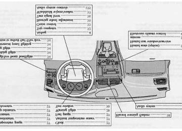
Volvo On Call 149pg. 142 Label information
1 Vehicle Emission Control Information Your Volvo is designed to meet all applicable emission standards, as evidenced by the certification label on the underside of the hood. For further information regarding these regulations, please consult your Volvo retailer.
2 Vacuum hose routing (underside of hood)
3 Loads and Tire Pressures (on inside of fuel filler door)
4 Model plate Vehicle Identification Number (VIN). Codes for color and upholstery, etc. The plate is located in the engine compartment, on the inside of the left front fender.
5 Vehicle Identification Number (VIN) * The VIN plate is located on the top left surface of the dashboard. The VIN is also stamped on the right hand door pillar.
6 Federal Motor Vehicle Safety Standards (FMVSS) specifications (USA) and Ministry of Transport (CMVSS) standards (Canada) Your Volvo is designed to meet all applicable safety standards, as evidenced by the certification label on the facing side of the driver's door. For further information regarding these regulations, please consult your Volvo retailer.
7 Child safety latch label
* The Vehicle Identification Number (VIN) should always be quoted in all correspondence concerning your vehicle with the retailer and when ordering parts.
All specifications are subject to change without prior notice.
pg. 143 Dimensions and weights
Dimensions
Length - 185.4 in. (471 cm), XC70 -186.2 (473 cm) Width - 71 in. (180 cm), XC70 - 73.2 in. (186 cm) Height - 57.5 in. (147 cm), V70 AWD - 58.7 in. (149 cm), XC70 - 61.5 in. 156 cm) Wheelbase - 108.5 in. (276 cm), XC70 - 108.8 in. (276 cm) Track, front - 61.5 in. (156 cm), XC70 - 63.4 in. (161 cm) Track, rear - 61.4 in. (156 cm), XC70 - 60.9 in. (155 cm) Turning circle (between curbs) - 35.8-39 ft. (10.9-11.9 m) Cargo capacity - 17.1 cu. ft. (0.48 m3 ) 1 - 26.3 cu. ft. (0.74 m3 ) 2 - 58.0 cu. ft. (1.64 m3 ) 3
USA Canada Max roof load 220 lbs 100 kg Max trailer weight (w/o brakes) 1100 lbs 500 kg Max trailer weight* - (with brakes, 2" ball) - (with brakes, 1 7/8" ball) Max tongue weight *
3300 lbs 1500 kg 2000 lbs 900 kg 165 lbs 75 kg
WARNING! When adding accessories, equipment, luggage and other cargo to your vehicle, the total loaded weight capacity of the vehicle must not be exceeded.
USA
Canada
2100 kg 2130 kg 2120 kg 2150 kg 2220 kg 2220 kg 420 kg
1) Rear seat backrest up, load height - upper edger of backrest 2) Rear seat backrest folded down, load height - upper edge of front seat backrests/lower edge of rear window 3) Rear seat backrest folded down, load height - headlining (ceiling) Weights Gross vehicle weight (GVW) V70 man. 4630 lbs 4690 lbs V70 aut. 4670 lbs V70 Turbo man. V70 Turbo aut. 4730 lbs 4890 lbs V70 AWD XC70
4890 lbs Capacity weight *** 930 lbs Curb weight V70
V70 AWD XC70
Permissible axle weight, front V70 man. 2290 lbs 2330 lbs V70 aut. 2400 lbs V70 Turbo aut. V70 AWD 2400 lbs XC70
2490 lbs Permissible axle weight, rear V70, V70 Turbo 2470 lbs 2580 lbs V70 AWD XC70
2620 lbs3390-3585 lbs 1541-1632 kg 3690-3725 lbs 1675-1695 kg 3765-3800 lbs 1710-1730 kg
1040 kg 1060 kg 1090 kg 1090 kg 1130 kg
1120 kg 1170 kg 1190 kg
* When driving for prolonged periods at temperatures above 86° F (30° C), the maximum recommended weight is 2000 lbs (900 kg). **See also section "Trailer towing" *** The max permissible axle loads or the gross vehicle weight must not be exceeded.
All specifications are subject to change without prior notice.
pg. 144 Engine specifications
Engine specifications Designation: Volvo B 5234 T3
Output Max. torque
247 hp at 5200 rpm (184 kW/87 rps) 243 ft. lbs. at 2400-5200 rpm (330 Nm/42-87 rps)
Number of cylinders 5
Bore Stroke Displacement Compression ratio Number of valves3.19" (81 mm) 3.54" (90 mm) 2.3 liters 8.5:1
20Designation: Volvo B 5254 T2
208 hp at 5000 rpm (154 kW/83 rps) 236 ft. lbs. at 1500-4500 rpm (320 Nm/25-75 rps)
Output Max. torque Number of cylinders 5
Bore Stroke Displacement Compression ratio Number of valves3.27" (83 mm) 3.67" (93.2 mm) 2.5 liters 9.0:1
20Designation: Volvo B 5244 T3
197 hp at 6000 rpm (147 kW/100 rps) 210 ft. lbs. at 1800-5000 rpm (285 Nm/30-83 rps)
Output Max. torque Number of cylinders 5
Bore Stroke Displacement Compression ratio Number of valves3.27" (83 mm) 3.54" (90 mm) 2.4 liters 9.0:1
20Designation: Volvo B 5244 S
168 hp at 6000 rpm (125 kW/100 rps) 166 ft. lbs. at 4500 rpm (225 Nm/75 rps)
Output Max. torque Number of cylinders 5
Bore Stroke Displacement Compression ratio Number of valves3.27" (83 mm) 3.54" (90 mm) 2.4 liters 10.3:1
20Charge air cooler (Intercooler) Turbocharged engines employ a turbo-compressor to force air into the engine inlet manifold and a charge air cooler to cool the compressed inlet air. The resulting increase in air flow raises pressure in the intake manifold and increases engine power over that developed by A normally-aspirated engine. The charge air cooler (which resembles a radiator) is located between the turbo-compressor and inlet manifold.
pg. 145 Transmission specifications
Power transmission
Manual transmission: M 56 LK Single-disc dry plate clutch. All-synchromesh on all gears including reverse; integrated final drive. Operation via a floor mounted gear lever. Final drive ratio 4.00:1
Reduction ratios 1st gear 3.39:1
2nd gear 1.91:1
3rd gear 1.19:1
4th gear 0.87:1
5th gear 0.70:1
Reverse 3.30:1Automatic transmission: AW 55-50
5-speed automatic electronically controlled gearbox comprising a hydraulic torque converter with a lock-up function; planetary gear, integrated final drive. Operation via a floor mounted gear selector lever. Drive shafts with symmetrical joint location. Overdrive.Final drive ratio 2.44:1* Reduction ratios AW5
1st gear 4.77:1
2nd gear 2.10:1
3rd gear 1.96:1
4th gear 1.32:1
5th gear 1.02:1
Reverse 3.23:1* XC70 2.65:1
pg. 146 Oil/fluid specifications and volumes
Engine Oil
Meeting or exceeding ILSAC specification GF-2, including ACEA A1, API SJ, SJ/CF, and SJ/Energy Conserving.
Oil additives must not be used.
Volume: Capacity (including oil filter): 6.1 US qts. (5.8 liters) Automatic Transmission Fluid
AW5: Only Volvo gearbox oil (1161540-8). Do not mix with other oils. Volume: 7.9 US qts (7.5 liters) Cooling system
Type: Positive pressure, closed system. The thermostat begins to open at 194 °F (90 °C)
Coolant: Volvo original coolant/antifreeze
All specifications are subject to change without prior notice. Power steering fluid
ATF fluid Volume: 0.95 US qts (0.9 liters) Brake fluid
DOT 4+ boiling point >536°F(280°C), P/N 9437433
Volume: 0.64 US qts (0.6 liters) Climate control system - refrigerant (R 134a)Oil: PAG Volume: 2.2 lbs (1,000 g) R134a Fuel
Minimum octane requirement - AKI 87 (RON 91) Volume (fuel tank): 18.5 US gals (70 liters) or 19 US gals (72 liters) on models equipped with All Wheel Drive. Washer fluid reservoir
Volume: 4.7 US qts (4.5 liters)
All specifications are subject to change without prior notice.
pg. 147 Fuel system, Distributor ignition system, Suspension
Fuel system
The engine is equipped with a multiport fuel injection system. Distributor ignition system
Firing order: 1-2-4-5-3 Electronic ignition setting: Not adjustable Spark plugs: Champion RC8PYP 8 (or equivalent) Spark plug gap: 0.028-0.032" (0.7-0.8 mm) Tightening torque: 18.4 ft. lbs. (25 Nm)
WARNING! The ignition system operates at very high voltages. Special safety precautions must be followed to prevent injury.
Always turn the ignition off when:
Replacing ignition components e.g. plugs, coil, etc. Do not touch any part of the ignition system while the engine is running. This may result in a shock and bodily
injury.
Front suspension
Spring strut suspension with integrated shock absorbers and control arms linked to the support frame. Power-assisted rack and pinion steering. Safety type steering column. The alignment specifications apply to an unladen car but include fuel, coolant and spare wheel. Rear suspension
Individual rear wheel suspension with longitudinal support arms, double link arms and track rods.
All specifications are subject to change without prior notice.
pg. 148 Electrical system
Electrical system
12 Volt, negative ground. Voltage-controlled generator. Single-wire system with chassis and engine used as conductors. Grounded on chassis.
Battery Voltage: 12 Volt, capacity: 600 A/115 min reserve capacity. The battery contains corrosive and poisonous acids. It is of the utmost importance that old batteries are disposed of correctly. Your Volvo retailer can assist you in this matter.
Generator Rated output: max. current: 140 A
Starter motor: Output: 1.7 kW Bulbs
Bulb Headlights - High beam - Low beam Front parking lights Front direction indicators Front fog lights Rear direction indicators Tail lights
US no. Power
Socket
HB3
H760W 55W 5W
(yellow) 21 W H1
55 W (yellow) 21W 5W 67W2.1x9.5d BAU 15d BAU 15 s BA 15 s
Brake lights Backup lights Rear fog light/rear parking lights License plate light Door step courtesy lights Front Cargo area lights Glove compartment light Vanity mirror light(s) Instrument lighting
1156
1156BA 15 s 21W 21W BA 15 s 21/4W BA 15 s 5 W
W 2.1x9.5d
SV 8.5
SV 8.5
BA 9s5W 5 W 2 W 12V 1.2W - 3 W
W 2.1x9.5d
All specifications are subject to change without prior notice.
pg. 149 Volvo On Call
Your new Volvo comes with a four year ON CALL road assistance. Additional information, features, and benefits are described in a separate information package in your glove compartment.
If you have misplaced your package, dial: In the U.S.A. 1-800-63-VOLVO (1-800-638-6586) In Canada: 1-800-263-0475
Technician certification
In addition to Volvo factory training, Volvo supports certification by the National Institute for Automotive Excellence (A.S.E.). Certified technicians have demonstrated a high degree of competence in specific areas. Besides passing exams, each technician must also have worked in the field for two or more years before a certificate is issued. These professional technicians are best able to analyze vehicle problems and perform the necessary service procedures to keep your Volvo at peak operating condition. All specifications are subject to change without prior notice.
Contents | Top of Page
2 0 0 3 VOLVO
V70
19
29
31
35
159
48 - 51
132
131
46
80, 81
8094
109
14
19
29
104, 131
76
65
39, 59
151
162
160
152
153
165
159
128INDEX
pg. 171 - 174 Index
ABS ABS - warning light Accessory lights Adjusting the steering wheel Advanced User Mode (AUM) - radio Air conditioning Air filter - engine Air pump system Air vents Airbag (SIPS) Airbag (SRS) Alarm Alarm - "panic" function All Wheel Drive - general information - using snow chains ALR/ELR Anti-lock Brake System (ABS) Anti-lock Brake System - warning light Antifreeze Approach lighting Armrest (center) - 3-section rear seat Ashtray Audio systems - cassette deck - CD player - HU-613 - overview - HU-803 - overview - specifications AUM (Advanced User Mode) - radio Automatic car washing
Automatic Locking Retractor (ALR) Automatic transmission - Geartronic - Kickdown Automatic transmission - cold starts Auxiliary socket AWD - general information - using snow chains Backrest (center) - 3-section rear seat Battery Battery maintenance - Replacing the battery - Ventilation hose Booster cushion Brake failure warning light Brake fluid Brake system Bulbs (list) Bulbs - replacing Capacities (oils and fluids) Cargo compartment cover Cargo compartment lighting Cargo eyelets Cargo net Catalytic converters - three-way Center armrest - 3-section rear seat Center backrest (3-section rear seat) Center console - switches Center head restraint - 3-section rear seat Center head restraint - rear seat Center seat head restraint Central locking buttons Chains - winter driving Changing wheels Child booster cushion Child Restraint Anchorages Child safety Child safety locks - rear doors Climate controls Climate system - general information Clock
14
90, 91, 145
92, 93
91, 92
91
31, 3994
10964
104, 148
138, 139
139
139
12, 16
28
137
18
148
120-125141, 146
71
67
68
69
106
65
64
31
64
63
79
109
112, 113
12, 16
15
11, 12, 14, 16
82
48-51
47
27Clutch interlock Coat hanger Coin compartment Cold weather driving Combination filter Coolant Cooling system - general information Courtesy light Courtesy lights (front) - replacing Courtesy lights - exterior Cruise control Cup holder Cup holder in the center console Detachable trailer hitch - installing Dimensions Direction indicators Distributor ignition system Door step courtesy lights - replacing Doors and locks Drive belt Driver's seat and remote keyless entry system Driving economy Driving mode indicator Driving mode W Driving with trunk open Economical driving Electric socket in cargo compartment Electrical system Electrical system - general information Electrically operated front seats Electrically operated sideview mirrors Electrically operated sun roof Electrically operated windows Electronic Brake Force Distribution Electronic Climate Control (ECC) Emergency Locking Retractor (ELR) Emergency towing Emergency warning flashers Emissions systems Engine - specifications Engine - starting Engine air filter
89
61
59
104
48, 51
131
96
74
124
76
33
59
60102
143
36
147
123
76
131
57
95
27
91, 93, 104
9695
67
148
96
56
41
42
40
19
48 - 51
14
99, 100
38
130
144, 145
87, 88
132Engine compartment Engine oil Extension of cargo compartment Exterior courtesy lights Exterior features - overview Extra seat Fog light - rear Fog lights - front Folding passenger's seat backrest Foldtable Front airbags - SRS Front airbags - SRS - warning light Front courtesy lights - replacing Front fog lights Front fog lights - replacing Front reading lights Front seats - adjusting Front seats - heated Front seats - manual adjustment Front suspension Fuel Fuel filler cap Fuel filter Fuel gauge Fuel requirements Fuel system Fuel tank cover Fuel/emissions systems Fuses Gas cap Gasoline Gear indicator Geartronic (automatic transmission) Generator Generator warning light Hand brake Handgrip - XC70
Handling Hazard warning flashers Head restraint (center) - 3-section rear seat Head restraint - center rear134
104, 135, 136
63
76
25
7329, 34
34
57
62
4 - 7
28
124
34
124
74
56
38
58
147
84
86
132
27
84
130, 132, 147
86
130
116-11986
84
27
92, 93
148
2839
55, 73
95
38
64Headlight bulbs - replacing Headlight wiper blades - replacing Headlights Heated front seats Heated rear window Heated sideview mirrors Heating Hoisting the car Holder for grocery bags Home Safe System HomeLink® Hood - opening Ignition switch Immobilizer (start inhibitor) Indicator lights Inflatable curtain (IC) Instrument illumination Instrument panel Instruments Integrated booster cushion Interior Air Quality system Interior features - overview Interior lighting Jack Jump starting Key - removing from ignition switch Keyless entry system Keyless entry system - replacing batteries Keylock Keys Kickdown Label information License plate lights - replacing Lifting the car Lights - accessory Load carriers Locking and unlocking the car Locking steering wheel Long distance trip Long loads
120
140
34
38
38
38
48-51
133
67
76
167-169
13435
76, 87
28, 29
34
27
26
12
51
24
7472, 112
10387
77, 78
78
87
76
91, 92142
124
133
31
97
76
35
105
5717
84
27
104, 135, 136
28
134129
29
52-54
89, 145
56
41
4169
69Maintenance schedule Malfunction indicator lamp Manual climate control with air conditioning Manual transmission Memory function - front seats Mirrors Mirrors, sideview - memory function Net - cargo Nylon cargo net Occupant safety Octane rating Odometer Oil - engine Oil pressure warning light Opening the hood Paint touch-up Panic function (alarm) Parking brake Parking brake reminder light Parking lights Passenger's seat backrest - folding PCV system Pen holder Polishing Power seats Power steering fluid Power windows 151
Radio 37
Rain sensor - windshield wipers 74
Reading lights - front/rear 29, 34
Rear fog light 74
Rear reading lights 66
Rear seat backrest 38
Rear window - heated 41
Rearview mirror 47
Refrigerant Refueling 86
Remote central locking system and sideview mirrors system 41
77
Remote control - keyless entry system126
80
39
28
34
57
132
61
128
56
137
40Remote control - Homelink® Universal Transceiver Remote keyless entry system Remote keyless entry system - replacing batteries Remote keyless entry system and driver's seat Removing the seat cushion Replacing bulbs Replacing fuses Replacing wiper blades Road assistance Roadholding Roof load - maximum Roof racks Safety locks - child Seat belt maintenance Seat belts Seat belts - cleaning Seats - front Securing cargo Servicing Shiftlock Side direction indicator - replacing Side impact airbag system (SIPS) Sideview mirrors Sideview mirrors - heated Sideview mirrors - memory function Snow chains Snow tires Spare tire Spark plugs Specifications SRS SRS diagnostic system Stability Traction Control (STC) Stain removal Start inhibitor (immobilizer) Starting the engine Steel grid Steering wheel adjustment Steering wheel lock Stop and Store bag Storage compartments Storage in the glove compartment Studded tires
168
77
78
57
66
120-125
116
140
149
95
143
9782
17
2, 3, 14
128
56
68
133
87, 90, 92
123
41
38
41
109
109
72, 110
132, 147
144
28
19, 31
128
76, 87
87, 88
69
35
35
64
59
60
109Subwoofer Sun roof Supplemental Restraint System Suspension Switches in center console Tachometer Tailgate - locking/unlocking Tailgate wiper blade - replacing Temperature gauge Temporary spare tire Text window Three-way catalytic converters Timing belt Tire pressure Tires Tires - changing Tool bag Towing a trailer Towing eyelet Towing the car Trailer towing Trailer weight - maximum Transmission - automatic Trip computer Trip odometer Turn signals Uniform tire quality grading Unlocking the tailgate Upholstery - cleaning Vanity mirror lights - replacing Vehicle Identification Number (VIN) Vehicle loading Ventilation Volvo On Call Volumes (oils and fluids) Warning flashers Warning light - center Warning lights Warranty Washer fluid reservoir
72, 166
42, 43
4, 28
147
3127
79
140
27
110
30
106
132
110
108 -111
112, 113
72
101
99
99, 100
101
143
90-94
32
27
36111
79
128124
142
110
46
149
14638
28
28, 29
129
133Washer fluid solvent Washing the car Waxing Weight distribution Wheels - changing Wheels and tires Whiplash Protection System (WHIPS) Windows - electrically operated Windshield washer solvent Windshield wiper blades - replacing Windshield wipers/washers Winter driving Winter tires Winter/Wet driving mode Wiper blades - replacing
104
127, 128
128
95
112, 113
108-113
10
40
104
140
37
104
109
91, 93, 104
140Contents | Top of Page
2 0 0 3 VOLVO
V70
Back Cover
Back Cover
Accessory Installation - Important Warning
We strongly recommend that Volvo owners install only genuine, Volvo-approved accessories, and that accessory
installations be performed only by the factory-trained technicians at your authorized Volvo retailer.
Genuine Volvo accessories are tested to ensure compatibility with the performance, safety, and emission systems in your car. Additionally, your authorized Volvo retailer knows where accessories may and may not be safely installed in your Volvo. In all cases, please consult your authorized Volvo retailer before installing any accessory in or on your car.
Accessories that have not been approved by Volvo may or may not be specifically tested for compatibility with your
car. Additionally, an inexperienced installer may not be familiar with some of your car's systems.
Any of your car's performance and safety systems could be adversely affected if you install accessories that Volvo
has not tested, or if you allow accessories to be installed by someone unfamiliar with your car.
Damage caused by unapproved or improperly installed accessories may not be covered by your new car warranty.
See your Warranty and Service Records Information booklet for more warranty information. Volvo assumes no responsibility for death, injury, or expenses that may result from the installation of non-genuine accessories.
Driver Distraction
Driver distraction results from driver activities that are not directly related to controlling the car in the driving environment. Your new Volvo is, or can be, equipped with many feature-rich entertainment and communication systems. These include hands-free cellular telephones, navigation systems, and multipurpose audio systems. You may also own other portable electronic devices for your own convenience. When used properly and safely, they enrich the driving experience. Improperly used, any of these could cause a distraction.
For all of these systems, we want to provide the following warning that reflects the strong Volvo concern for your
safety:
parked.
Never use these devices or any feature of your vehicle in a way that distracts you from the task of driving safely.
In addition to this general warning, we offer the following guidance regarding specific newer features that may be
Never use a hand-held cellular telephone while driving. Some jurisdictions prohibit cellular telephone use by a
Distraction can lead to a serious accident.
found in your vehicles:
driver while the vehicle is moving.
If your car is equipped with a navigation system, set and make changes to your travel itinerary only with the vehicle
Never program your audio system while the vehicle is moving. Program radio presets with the vehicle parked, and
use your programmed presets to make radio use quicker and simpler.
Never use portable computers or personal digital assistants while the vehicle is moving.
A driver has a responsibility to do everything possible to ensure his or her own safety and the safety of passengers in
the vehicle and others sharing the roadway. Avoiding distractions is part of that responsibility.
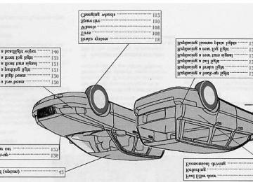
The following should be checked regularly: *
1 Washer fluid reservoir should be filled with water and solvent (wintertime: windshield washer anti-freeze). See page 133.
2 Power steering - When cold, the level must not be above the COLD mark and when hot it must not be above the HOT mark. Top up if the level drops to the ADD mark with ATF fluid. See page 137.
3 Coolant level should be between the expansion tank marks. Mixture: 50% anti-freeze and 50% water. See page 131.
4 Engine oil level should be between the dipstick marks. The distance between the marks represents approx. 1.6 US qts (1.5 liters). See page 135.
5 Brake fluid - check, without removing the cap, that the level is above the MIN mark. Use brake fluid DOT 4+. See page 137.
* Engine oil should be checked each time the car is refuelled.
Octane rating, see page 84.
Tire pressure, see label located on the rear edge of the right front door.
Bulbs Power Socket US no. US no. Bulb Power Socket 60 W HB 3
55 W H 7
21 W BAU 15d - 21 W BA 15s 55 W H 1
5 W W W2.1x9.5d 1157NA 21/4 W BA 15d 5 W BA 15s1156
67
Contents | Top of Page