- 2013 Volvo S60 Owners Manuals
- Volvo S60 Owners Manuals
- 2004 Volvo S60 Owners Manuals
- Volvo S60 Owners Manuals
- 2012 Volvo S60 Owners Manuals
- Volvo S60 Owners Manuals
- 2006 Volvo S60 Owners Manuals
- Volvo S60 Owners Manuals
- 2003 Volvo S60 Owners Manuals
- Volvo S60 Owners Manuals
- 2007 Volvo S60 Owners Manuals
- Volvo S60 Owners Manuals
- 2001 Volvo S60 Owners Manuals
- Volvo S60 Owners Manuals
- 2005 Volvo S60 Owners Manuals
- Volvo S60 Owners Manuals
- 2008 Volvo S60 Owners Manuals
- Volvo S60 Owners Manuals
- 2011 Volvo S60 Owners Manuals
- Volvo S60 Owners Manuals
- 2002 Volvo S60 Owners Manuals
- Volvo S60 Owners Manuals
- 2009 Volvo S60 Owners Manuals
- Volvo S60 Owners Manuals
- Download PDF Manual
-
switched off at any time by pressing the button.
pg. 105 Floor mats (option)
Vanity mirror The light comes on when you open the cover.
Floor mats (option) Volvo offers floor mats specially manufactured for your car. They must be properly placed and secured in the mat clips.
WARNING!
An extra mat on the driver's floor can cause the accelerator pedal to catch. Check that the movement of the accelerator pedal is not impeded. No more than one protective floor covering may be used at one time.
Contents | Top of Page
2 0 0 1 VOLVO
S60
Safety pg. 9 Safety
Seat belts 10
Airbags (Supplemental Restraint System) 12
Side airbags (SIPS airbags) 18
Inflatable Curtain (IC) 20
Inspection of airbags, inflatable curtains and seat belt tensioners 21
22
WHIPS Child safety 24
Occupant safety, Reporting safety defects 28
pg. 10 Seat belts Seat beltsNot wearing a seat belt is like believing "It'll never happen to me!" Volvo, the inventor of the three-point seat belt, urges you and all occupants of your car to wear seat belts and ensure that children are properly restrained, using an infant, car or booster seat determined by age, weight and height. Volvo also believes no child should sit in the front seat of a car.
NOTE: Legislation in your state or province may mandate seat belt usage. Additionally, most states and provinces have already made it mandatory for occupants of a car to use seat belts.
So, urging you to "buckle up" is not just our recommendation - legislation in your state or province may mandate seat belt usage. The few seconds it takes to buckle up may one day allow you to say, "It's a good thing I was wearing my seat belt."
NOTE: A chime will sound several times if the driver has not fastened his/ her seat belt.
To buckle a seat belt:
Pull the belt out far enough to insert the latch plate into the receptacle until a distinct click is heard. The seat belt retractor is normally "unlocked" and you can move freely, provided that the shoulder belt is not pulled out too far. The retractor will lock up as follows:
if the belt is pulled out rapidly during braking and acceleration if the vehicle is leaning excessively when driving in turns For the seat belt to provide maximum protection in the event of an accident, it must be worn
correctly. When wearing the seat belt remember:
The belt should not be twisted or turned. The lap belt must be positioned low on the hips (not pressing against the abdomen).
Make sure that the shoulder belt is rolled up into its retractor and that the shoulder and lap belts are taut.
Before exiting the car, check that the seat belt retracts fully after being unbuckled. If necessary, guide the belt back into the retractor slot.
Child seats: Please refer to page 27 for information on securing child seats with the seat belts.
pg. 11 Seat belts
During pregnancy Pregnant women should always wear seat belts. Remember that the belt should always be positioned in such a way as to avoid any possible pressure on the abdomen. The lap portion of the belt should be located low, as shown in the above illustration.
WARNING!
Seat belts:
Never use a seat belt for more than one occupant. Never wear the shoulder portion of the belt under the arm,
behind the back or otherwise out of position. Such use could cause injury in the event of an accident. As seat belts lose much of their strength when exposed to violent stretching, they should be replaced after any collision, even if they appear to be undamaged.
Never repair the belt on your own; have this work done by an authorized Volvo retailer only. Any device used to induce slack into the shoulder belt portion of the three-point belt system will have a
detrimental effect on the amount of protection available to you in the event of a collision.
The seat back should not be tilted too far back. The shoulder belt must be taut in order to function properly. Do not use child safety seats or child booster cushions/ backrests in the front passenger's seat. We also
recommend that children who have outgrown these devices sit in the rear seat with the seat belt properly fastened.
pg. 12 Airbags (Supplemental Restraint System)
Driver's side airbag As an enhancement to the three-point seat belt system, your Volvo is equipped with a Supplemental Restraint System (SRS) to complement the three-point seat belt system. The inflatable airbag is installed folded up in the center of the steering wheel. The wheel is embossed with SRS.
WARNING!
Never drive an SRS equipped car with your hands on the steering wheel pad / airbag housing.
Passenger side airbag The airbag on the front passenger side is folded up in a compartment above the glove compartment. The panel is embossed SRS.
WARNING!
No objects, accessory equipment or stickers may be placed on, attached to, or installed near the SRS cover in the center of the steering wheel, the SRS cover above the glove compartment or the area affected by airbag deployment.
WARNING!
As its name implies, SRS is designed to be a SUPPLEMENT to - not a replacement for - the three-point belt system. For maximum protection, wear seat belts at all times. Be aware that no system can prevent all possible injuries that may occur in an accident.
When installing any optional equipment, make sure that the SRS system is not damaged. Do not attempt to service any component of the SRS yourself. Attempting to do so may result in serious personal injury. If a problem arises, take your car to the nearest authorized Volvo retailer for inspection as soon as possible.
pg. 13 Airbags (Supplemental Restraint System)
NOTE: Deployment of SRS components occurs only one time during an accident. In a collision where deployment occurs, the airbags and seat belt tensioners activate. Some noise occurs and a small amount of powder is released. The
release of the powder may appear as smoke- like matter. This is a normal characteristic and does not indicate fire.
NOTE: Volvo's dual- threshold, dual- stage airbags use special sensors that are integrated with the front seat buckles. The point at which the airbag deploys is determined by whether or not the seat belt is being used, as well as the severity of the collision. Collisions can occur where only one of the airbags deploys.
If the impact is less severe, but severe enough to present a clear injury risk, the dual- stage airbags are triggered at just 70% of their total capacity. If the impact is more severe, the dual- stage airbags are triggered at full capacity.
WARNING!
Do not use child safety seats or child booster cushions/ backrests in the front passenger's seat. We also recommend that occupants under 4 feet 7 inches (140 cm) in height who have outgrown these devices sit in the rear seat with the seat belt fastened. Never drive with the airbags deployed. The fact that they hang out can impair the steering of your car. Other safety systems can also be damaged. The smoke and dust formed when the airbags are deployed can cause skin and eye irritation in the event of prolonged exposure.
pg. 14 Airbags (Supplemental Restraint System)
WARNING!
Children must never be allowed in the front passenger's seat. Volvo recommends that ALL occupants (adults and children) shorter than 4 feet 7 inches (140 cm) be seated in the back seat of any vehicle with a front passenger-side airbag. See page 28 for guidelines.
Occupants in the front passenger's seat must never sit on the edge of the seat, sit leaning toward the instrument panel or otherwise sit out of position. The occupant's back must be as upright as comfort allows and be against the seat back with the seat belt properly fastened.
Feet must be on the floor, e. g. not on the dash, seat or out of the window. No objects or accessory equipment, e. g. dash covers, may be placed on, attached to, or installed near the SRS hatch (the area above the glove compartment) or the area affected by airbag deployment (see illustration on page 12).
There should be no loose articles, e. g. coffee cups, on the floor, seat or dash area. Never try to open the SRS cover on the steering wheel or the passenger side dash. This should only be done by an authorized Volvo service technician.
Failure to follow these instructions can result in injury to the vehicle occupants
Warning light in the instrument panel A self- diagnostic system incorporated in the sensor monitors the SRS. This system does not, however, monitor the Side Impact Protection System (SIPS) airbags. If a fault is detected, the warning light will illuminate. The light is included in the warning/ indicator light cluster in the instrument panel. Normally, the SRS warning lamp should light
up when the ignition key is turned to positions I, II or III and should go out after 7 seconds or when the engine is started. Check that this light is functioning properly every time the car is started.
The following items are monitored by the self- diagnostic system:
Sensor unit Cable harness Gas generator
WARNING!
If the SRS warning light stays on after the engine has started or if it comes on while you are driving, drive the car to the nearest authorized Volvo retailer for inspection as soon as possible.
pg. 15 Airbags (Supplemental Restraint System) NOTE: The information on this page does not pertain to the Side Impact Protection System airbags.
When are the airbags deployed? The SRS system is designed to deploy during certain frontal or front-angular collisions, impacts, or decelerations, depending on the crash severity, angle, speed and object impacted. The SRS sensor is designed to react to both the impact of the collision and the inertial forces generated by it and to determine if the intensity of the collision is sufficient for the seat belt tensioners or airbags to be deployed. If the airbags have been deployed, we recommend the following:
Have the car towed to an authorized Volvo retailer. Never drive with the airbags deployed. Have an authorized Volvo retailer replace the SRS system components. Use only new, Genuine Volvo Parts when replacing SRS components (airbags, seat belts, tensioners, etc.).
When are the airbags NOT deployed? Not all frontal collisions activate the SRS system. If the collision involves a nonrigid object (e. g., a snow drift or bush), or a rigid, fixed object at a low speed, the SRS system will not necessarily deploy. Front airbags do not normally deploy in a side impact collision, in a collision from the rear or in a rollover situation. The amount of damage to the bodywork does not reliably indicate if the airbags should have deployed or not.
Seat belts - the heart of the Volvo safety system The heart of the Volvo safety system is the three-point seat belt (a Volvo invention)! In order for the SRS system to provide the protection intended, seat belts must be worn at all times by everyone in the car. The SRS system is a supplement to the seat belts.
WARNING!
Never drive with the airbags deployed. The fact that they hang out can impair the steering of your car. Other safety systems can also be damaged. The smoke and dust formed when the airbags are deployed can cause skin and eye irritation in the event of prolonged exposure.
pg. 16 Airbags (Supplemental Restraint System)
WARNING!
If your car has been subjected to flood conditions (e. g. soaked carpeting/ standing water on the floor of the vehicle) or if your car has become flood-damaged in any way, do not attempt to start the vehicle or put the key in the ignition before discon- necting the battery (see below). This may cause airbag deployment which could result in personal injury. Have the car towed to an authorized Volvo retailer for repairs.
Automatic transmission: Before attempting to tow the car, use the following procedure to override the shiftlock system to move the gear selector to the neutral position.
Switch off the ignition for at least 10 minutes and disconnect the battery Wait at least one minute Insert the key in the ignition and turn it to position II Press firmly on the brake pedal. Move the gear selector from (P) ark to the (N) eutral position.
There is no maintenance to perform on the SRS yourself. The month and year shown on the decal on the door pillar indicate when you should contact your Volvo retailer for specific servicing or replacement of airbags and seat belt tensioners. This service must be performed by an authorized Volvo retailer.
Should you have any questions about the SRS system, please contact your authorized Volvo retailer or Volvo Customer Support.:
In the USA: Volvo Cars of North America Customer Relations P.O. Box 914 Rockleigh, New Jersey 07647-0914 800-458-1552
In Canada: Volvo Canada Ltd. 175 Gordon Baker Road Willowdale, Ontario M2H 2N7 800-663-8255
pg. 17 Airbags (Supplemental Restraint System)
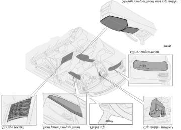
Front airbag (SRS) system As an enhancement to the three-point seat belt system, your Volvo is equipped with a Supple- mental Restraint System (SRS). The Volvo SRS consists of an airbag (2) on both the driver's and passenger's sides and seat belt tensioners in both front door pillars. The system is designed to supplement the protection provided by the three-point seat belt system. All three rear seat belts are also equipped with tensioners.
The SRS system is indicated by the "SRS" embossed on the steering wheel pad and above the glove compartment, and by decals on both sun visors and on the front and far right side of the dash.
The airbags are folded and located in the steering wheel hub and above the glove compartment.
Deployment: The SRS airbags are designed to deploy during certain frontal or front-angular collisions, impacts, or decelerations, depending on the crash severity, angle, speed and object impacted. The airbags may also deploy in certain non-frontal collisions where rapid deceleration occurs.
The airbag system includes gas generators (1) surrounded by the airbags (2) and front seat belt tensioners for both of the front seats. To deploy the system, the sensor (3) activates the gas generators causing the airbags to be inflated with nitrogen gas.
As the movement of the seats' occupants compresses the airbags, some of the gas is expelled at a controlled rate to provide better cushioning. Both seat belt tensioners also deploy, minimizing any seat belt slack. The entire process, including inflation and deflation of the airbags, takes approximately two-tenths of a second.
WARNING!
injury. Deployment occurs very quickly and with considerable force. During normal deployment and depending on variables such as seating position, one may experience abrasions, bruises, swellings, or other injuries as a result of airbag( s) deployment.
Never try to repair any part of the SRS or SIPS bag systems yourself. Any interference in the system could cause malfunction and serious injury. All work on these systems should be performed by an authorized Volvo retailer.
pg. 18 Side airbags (SIPS airbags)
SIPS airbag (front seats only) As an enhancement to the structural Side Impact Protection System built into your car, the car is also equipped with Side Impact Protection System (SIPS) airbags. The SIPS airbag system consists of airbag modules built into the sides of both front seat backrests, wires and gas generators/ sensor units (see illustration on next page).
The SIPS airbag system is designed to help increase occupant protection in the event of certain side impact collisions. The SIPS airbags are designed to deploy only during certain side- impact collisions, depending on the crash severity, angle, speed and point of impact. The airbags are not designed to deploy in all side impact situations.
NOTE: SIPS airbag deployment (one airbag) occurs only on the side of the vehicle affected by the impact. The airbags are not designed to deploy in all side impact situations.
*A SIPS airbag warning decal is also located at the end of the instrument panel on the driver's side of the car.
WARNING!
the Side Impact Protection System and the three-point seat belt system. It is not designed to deploy during collisions from the front or rear of the car or in rollover situations.
The use of seat covers on the front seats may impede SIPS airbag deployment.
No objects, accessory equipment or stickers may be placed on, attached to or installed near, the SIPS airbag system or in the area affected by SIPS airbag deployment (see illustration in the center column above). Never try to open or repair any components of the SIPS airbag system. This should be done only by an authorized Volvo service technician.
In order for the SIPS airbag to provide its best protection, both front seat occupants should sit in an upright position with the seat belt properly fastened.
Failure to follow these instructions can result in injury to the occupants of the vehicle in the event of an accident.
pg. 19 Side airbags (SIPS airbags)
The SIPS airbag system This system consists of a gas generator (1), the side airbags (2), and electronic sensors/ cables (3).
Contents | Top of Page
2 0 0 1 VOLVO
S60
Locks and alarm pg. 115 Locks and alarm Keys and remote controls 116
119
Locking and unlocking Child safety lock 121
122
Alarmpg. 116 Keys and remote controls
Keys Two keys are provided with your car; a master key and a service key. The master key, the remote control, and the central locking button may all be used to lock and unlock all of your car's locks.
The service key will operate only the driver's door and the ignition switch. It is intended to help deter unwanted entry into the glove compartment and trunk.
Turn the key once to unlock the driver's door only. Turn the key again (within 10 seconds) to unlock all doors and the trunk. One turn with the key towards lock in the drivers door locks all doors, trunk. Use the switch on the driver's door armrest to lock/ unlock the car from the inside.
NOTE: To help prevent accidentally locking the keys in the car, the central locking system is designed to unlock the
doors immediately if the key is left in the ignition switch, the car is locked using the lock button on the door and the door is then closed. A sound from the lock will be audible at this time. Please note that this function will not unlock the doors if the engine is running.
Immobilizer (start inhibitor) Each of the keys supplied with your car contains a coded transmitter. The code in the key is transmitted to an antenna in the ignition switch where it is compared to the code stored in the start inhibitor module. The car will start only with a properly coded key.
If you misplace a key, take the other keys to an authorized Volvo retailer for reprogramming as an antitheft measure.
NOTE: This device complies with part 15 of the FCC rules. Operation is subject to the following condition: (1) This device may not cause harmful interference, and (2) this device must accept any interference received, including interference that may cause undesired operation.
WARNING!
If the doors are locked while driving, this may hinder rapid access to the occupants of the car in the event of an accident. (Also see information on "Child safety locks"
pg. 117 Keys and remote controls
Remote controls Your car is equipped with a remote control transmitter. This transmitter uses a radio signal to allow "keyless" entry into the passenger compartment or the trunk. You will be supplied with two coded key ring transmitters, which will enable you to lock/ unlock all doors and the trunk from a distance of 10- 15 feet (3- 5 meters).
On vehicles equipped with an alarm, the alarm will also be activated/ deactivated by this system.
The car can also be locked/ unlocked with the key.
As an extra security precaution in certain situations (valet parking, etc.), Volvo recommends that the transmitter not be included when the keys are given to anyone. The service key can be used instead. If one of the transmitters is misplaced, contact the nearest authorized Volvo retailer for assistance.
Using the remote control
Press the LOCK button once to lock all doors and trunk. Press the UNLOCK button once to unlock the driver's door and fuel filler door. Press this button again (within 10
seconds) to unlock all doors and the trunk.
To pop open the trunk (without unlocking the doors), press the OPEN trunk button twice within 3 seconds.
NOTE:
Airbag deployment will automatically unlock the doors. The keys may also be used to lock and unlock the doors, and to activate and deactivate the alarm system. To avoid leaving your keys in the car, make a habit of always locking the car with the remote control.
* See page 122 for more information on this function.
pg. 118 Keys and remote controls Automatic locking (retailer installed option on certain models) If your car is equipped with this option, all unlocked doors will automatically be locked when the car exceeds a speed of 3 mph (5 km/ h).
Please be aware of the following:
If the doors are unlocked using the central locking button after the doors have automatically locked and no door has
been opened, the doors will not automati- cally re-lock the next time the car exceeds 3 mph (5 km/ h).
If any doors are unlocked by pulling up the lock knob after the doors have been automatically locked and no door
has been opened, the doors will not automati- cally re-lock the next time the car exceeds 3 mph (5 km/ h).
If a door is opened after the car has exceeded 3 mph (5 km/ h), that door will not be re- locked.
Automatic re-locking If the doors are unlocked, the locks will automatically reengage (re-lock) and the alarm will reset after 2 minutes unless a door or the trunk has been opened.
WARNING!
Never use the transmitter to lock the doors from inside the car
Doing so would ACTIVATE:
the break
in alarm, which would sound if one of the doors were opened the optional interior motion and inclination alarm sensors.
Doing so would DEACTIVATE:
the sunroof and interior courtesy light controls. the central locking buttons on the front door armrests, although the interior door handles would still function to
allow occupants to leave the car.
Disabled features would remain disabled until the remote were used again to unlock the car.
In addition, locking an occupied vehicle would hinder rapid access to the occupants in an accident or emergency.
Replacing the battery in the remote control If the range of the transmitter is noticeably reduced, this indicates that the battery is weak and should be replaced.
To replace the battery
Remove the screw on the transmitter cover with a small screwdriver. Remove the cover carefully pressing it rearward/ upward. Replace the battery with a new 3- volt, CR 2032 battery. The battery should be inserted with the minus side
upward. Avoid touching the contact surfaces of the battery with your fingers.
Reinstall the cover and tighten the screw to help protect the transmitter.
pg. 119 Locking and unlocking
Locking and unlocking the car from the inside The switch on the driver's door armrest can be used to lock or unlock all doors and the trunk, and to set the alarm.
Locking the glove compartment The glove compartment can be locked with the master key.
pg. 120 Locking and unlocking
Opening/ locking the trunk lid with the remote control Do as follows to unlock the trunk lid only:
Press the "Open trunk" button on the remote control twice. If all doors are locked when you close the trunk lid, it
locks automatically.
Unlocking the trunk lid with the master key The master key should only be used to unlock the trunk lid in emergencies (if the remote control is not working or the car is without power). Open the trunk lid as follows:
Insert the master key into the upper or lower part of the plug covering the lock. Twist upward or downward to remove the plug. Unlock the trunk lid.
pg. 121 Child safety lock
Manual child safety locks - rear doors The controls are located on the rear door jambs. Use a screwdriver to adjust these controls.
A The door cannot be opened from the inside. Normal operation from the outside.
B The door lock functions normally.
WARNING!
Remember, in the event of an accident, the rear seat passengers cannot open the doors from the inside with the buttons in position A
pg. 122 Alarm Alarm The alarm is automatically armed whenever you lock your car.
When armed, the alarm continuously monitors a number of points on the car. The following conditions will set off the alarm:
The hood is forced open. The trunk is forced open. A door is forced open. The ignition switch is tampered with. If there is movement in the passenger compartment (if the car is equipped with the optional movement sensor). The car is lifted or towed (if the car is equipped with the optional inclination sensor). The battery is disconnected (while the alarm is armed). The siren is disconnected when the alarm is disarmed.
Arming the alarm Press the LOCK button on the remote control, lock the car using the key in the driver's door or press the central lock button on one of the front doors with the door open. One long flash of the turn signals will confirm that the alarm is armed.
Disarming the alarm Press the UNLOCK button on the remote control or unlock the doors with the key.
Turning off (stopping) the alarm If the alarm is sounding, it can be stopped by pressing the UNLOCK button on the remote control or by unlocking the driver's door with the key.
Visual alarm signal The visual alarm signal is given by flashing all turn signals and turning on the interior lighting for approximately 5
minutes.Audible alarm signal An audible alarm signal is given by a battery powered siren. One alarm cycle lasts for 25 seconds.
"Panic" button In an emergency situation, this feature can be used to attract attention.
Activate the "panic" button by pressing the red button on the remote control (see illustration on page 117) for at least 3 seconds or by pressing this button twice within 3 seconds. The turn signals will flash, the interior lights will go on and the car's horn will sound.
The function can be turned off by pressing any of the buttons on the remote control or will stop automatically after 25
seconds. When a button is pressed, there is a 5 second delay before the panic alarm is deactivated.NOTE: This button will NOT unlock the car.
pg. 123 Alarm
Temporarily turning off the alarm sensor( s) - option This button will only be found in cars equipped with the optional inclination and/ or movement sensors.
In certain situations it may be desirable to turn off the optional inclination and movement alarm sensors if, for example, you drive your car onto a ferry where the rocking of the boat could trigger the alarm or if a pet is left in the car with the doors locked.
To temporarily turn off the inclination and movement alarm sensors from the alarm system:B From the time the ignition key is turned from the Drive position (position II) until you lock the car, you can press the button in the
center console*. The LED in the switch will light up and a message will be displayed in the text window to indicate that the sensors are disconnected.
The car can then be locked in the usual way to set the alarm.
NOTE: The optional sensors are automatically reconnected to the alarm system the next time the car is unlocked and then locked again.
LED alarm status signals The status of the alarm system is indicated by the red LED at the top of the dash:
LED off - the alarm is not armed LED flashes once per second - the alarm is armed LED flashes rapidly before the ignition is switched on - the alarm has been triggered Fault in the alarm system: If a fault has been detected in the alarm system, a message will be displayed in the text
window. Contact your Volvo retailer.
Automatic re-lock/ re-arm system If the car is unlocked with the remote, the car will re- lock and the alarm will re- arm after 2 minutes unless a door or the trunk has been opened.
* The position of this button may vary, depending on the specifications of your car.
Contents | Top of Page
2 0 0 1 VOLVO
S60
Starting and driving pg. 125 Starting and driving 126
Refueling 128
Starting the car 130
General information 132
Manual transmission 133
Automatic transmission (option) 135
Geartronic (option ) 137
Brake system 139
Stability system 141
Towing 143
Jump starting Towing a trailer 144
Detachable trailer hitch - installing 146
Detachable trailer hitch - removing 147
148
Attaching load carriers Cold weather precautions 149
150
Before a long distance trippg. 126 Refueling ENGINE OIL Although some oil consumption occurs during normal engine operation, more oil is consumed when the engine is new as the internal parts generate higher friction while wearing- in to each other. From the time the engine is new until the first service is performed, the oil consumption could be higher than normal. For this reason, it is especially important to check the oil every time you refuel your car during this period. See page 172.
Fuel requirements Octane rating Volvo engines are designed for optimum performance on unleaded premium gasoline with an AKI octane rating of 91
or above. AKI (ANTI KNOCK INDEX) is an average of the Research Octane Number, RON, and the Motor Octane Number, MON. (RON + MON/ 2). The minimum octane requirement is AKI 87 (RON 91).Deposit control gasoline (detergent additives) Volvo recommends the use of gasoline containing deposit control additives. These additives have shown to be effective in keeping injectors and intake valves clean. Consistent use of deposit control gasolines will help ensure good driveability and fuel economy. If you are not sure whether the gasoline contains deposit control additives, check with the service station operator.
NOTE: Volvo does not recommend the use of external fuel injector cleaning systems. Unleaded fuel Each Volvo has a three-way catalytic converter and must use only unleaded gasoline. U. S. and Canadian regulations require that
pumps deliv- ering unleaded gasoline be labelled "UNLEADED". Only these pumps have nozzles which fit your car's filler inlet. It is unlawful to dispense leaded fuel into a vehicle labelled "unleaded gasoline only". Leaded gasoline damages the three- way catalytic converter and the heated oxygen sensor system. Repeated use of leaded gasoline will lessen the effectiveness of the emission control system and could result in loss of emission warranty coverage. State and local vehicle inspection programs will make detection of misfueling easier, possibly resulting in emission test failure for misfueled vehicles.
NOTE: Some U. S. and Canadian gasolines contain an octane enhancing additive called methyl- cyclopentadienyl manganese tricar- bonyl (MMT). If such fuels are used, your Emission Control System performance may be affected, and the Check Engine Light (malfunction indicator lamp) located on your instrument panel may light. If this occurs, please return your vehicle to an authorized Volvo retailer for service.
Gasoline containing alcohol and ethers "Oxygenated fuels"
Some fuel suppliers sell gasoline containing "oxygenates" which are usually alcohols or ethers. In some areas, state or local laws require that the service pump be marked indicating use of alcohols or ethers. However, there are areas in which the pumps are unmarked. If you are not sure whether there is alcohol or ethers in the gasoline you buy, check with the service station operator. To meet seasonal air quality standards, some areas require the use of "oxygenated" fuel.
Volvo allows the use of the following "oxygenated" fuels; however, the octane ratings listed on this page must still be met.
Alcohol - Ethanol: Fuels containing up to 10% ethanol by volume may be used. Ethanol may also be referred to as Ethyl alcohol, or "Gasohol".
Ethers - MTBE: Fuels containing up to 15% MTBE may be used.
pg. 127 Refueling
Fuel filler door The fuel filler door, located on the right rear fender, is connected to your car's central locking system. The driver's door must be unlocked before the fuel filler door can be opened.
Be sure the fuel filler door is not obstructed and is completely closed after refueling. Open the fuel filler cap slowly during hot weather.
NOTE: During a transitional period, a small number of service stations may still have fuel nozzles that are not compatible with the fuel filler neck on cars equipped with the evaporative control system.
Refueling The fuel tank is designed to hold approximately 18.5 US gals (70 liters) or 21.1 US gals (80 liters) on turbo models,
with sufficient volume left over to accommodate possible expansion of the fuel in hot weather. Be aware that the "usable" tank capacity will be somewhat less than the specified maximum. When the fuel level is low, such factors as ambient temper- ature, the fuel's "Reid vapor pressure" charac- teristics, and terrain can affect the fuel pump's ability to supply the engine with an adequate supply of fuel. Therefore, it is advisable to refuel as soon as possible when the needle nears the red zone, or when the fuel warning light comes on.
CAUTION: Do not refuel with the engine running *. Turn the ignition off or to position I. If the ignition is on, an incorrect reading could occur in the fuel gauge After refueling, close the fuel filler cap by turning it clockwise until it clicks into place*.
Allow for fuel expansion by not overfilling the tank. Overfilling could also cause damage to the emission control systems. Avoid spilling gasoline during refueling. In addition to causing damage to the environment, gasolines containing alcohol can cause damage to painted surfaces, which may not be covered under the New Vehicle Limited Warranty.
Do not use gasolines containing methanol (methyl alcohol, wood alcohol). This practice can result in vehicle performance deterioration and can damage critical parts in the fuel system. Such damage may not be covered under the New Vehicle Limited Warranty.
* If the fuel filler cap is not closed tightly or if the engine is running when the car is refueled, the Check Engine Light (malfunction indicator lamp) may indicate a fault. However, your vehicle's performance will not be affected. Use only Volvo original or approved fuel filler caps.
pg. 128 Starting the car Starting the engine 1. Fasten the seat belt.
WARNING!
Before starting, check that the seat, steering wheel and mirrors are adjusted properly. Make sure the brake pedal can be depressed completely. Adjust the seat if necessary. See pages 100, 102. 2. Apply the parking brake (hand brake) if not already set. The gear selector (automatic transmission) is locked in the (P) ark position (SHIFTLOCK). Manual transmission: the clutch must be fully depressed.
3. Without touching the accelerator pedal, turn the ignition key* to the starting position. Allow the starter to operate for up to 10 seconds. Release the key as soon as the engine starts. If the engine fails to start, repeat this step. For cold starts at altitudes above 6000 ft (1800 meters), depress the accelerator pedal halfway and turn the key to the starting position. Release the pedal slowly when the engine starts.
4. To release the gear selector from the (P) ark position, the engine must be running (or theignition key must be in position II) and the brake pedal must be depressed.
5. Select the desired gear. The gear engages after a very slight delay which is especially noticeable when selecting R.
NOTE: Your car is equipped with a KEYLOCK system (automatic transmission). When the engine is switched off, the gear selector must be in the (P) ark position before the key can be removed from the ignition switch. When starting in cold weather, the transmission may shift up at slightly higher engine speeds than normal until the automatic transmission fluid reaches normal operating temperature.
CAUTION:
Automatic transmission The engine should be idling when you move the gear selector. Never accelerate until after you feel the transmission engage! Acceler- ating immediately after selecting a gear will cause harsh engagement and premature transmission wear. Selecting P or N when idling at a standstill for prolonged periods of time will help prevent overheating of the automatic trans- mission fluid.
WARNING!
Always place the gear selector in Park and apply the parking brake before leaving the vehicle. Never leave the car unattended with the engine running. Always open garage doors fully before starting the engine inside a garage to ensure adequate ventilation. The exhaust gases contain carbon monoxide, which is invisible and odorless but very poisonous Do not race a cold engine immediately after starting. Oil flow may not reach some lubrication points fast enough to prevent engine damage.
* If two of the keys to your car are close together, e. g., on the same key ring, when you try to start the car, this could cause interference in the immobilizer system and result in the car not starting. If this should occur, remove one of the keys from the key ring before trying to start the car again.
pg. 129 Starting the car Ignition switch and steering wheel lock 0 Locked position: Remove the key to lock the steering wheel *.
WARNING!
Never turn the key to position O while driving or when the car is being towed.
I Intermediate position - "radio position": Certain accessories, radio, etc. on, daytime running lights off.
II Drive position: The key position when driving. The car's entire electrical system is connected.
III Start position: Release the key when the engine starts. The key returns automatically to the Drive position.
A chime will sound if the key is left in the ignition and the driver's door is opened.
* The gear selector must be in the (P) ark position (automatic transmission).
Steering wheel lock The steering wheel lock might be under tension when the car is parked. Turn the steering wheel slightly to free the ignition key.
In order to help reduce car theft, make sure the steering wheel lock is engaged before leaving the car.
pg. 130 General information Economical driving conserves natural resources Better driving economy may be obtained by thinking ahead, avoiding rapid starts and stops and adjusting the speed of your vehicle to immediate traffic conditions. Observe the following rules:
Bring the engine to normal operating temperature as soon as possible by driving with a light foot on the accel- erator pedal for the first few minutes of operation. A cold engine uses more fuel and is subject to increased wear.
Whenever possible, avoid using the car for driving short distances. This does not allow the engine to reach normal
operating temperature.
Drive carefully and avoid rapid acceler- ation and hard braking. Do not exceed posted speed limits. Avoid carrying unnecessary items (extra load) in the car. Maintain correct tire pressure. Check tire pressure regularly (when tires are cold). Remove snow tires when threat of snow or ice has ended. Note that roof racks, ski racks, etc, increase air resistance and also fuel consumption. Avoid using automatic transmission kickdown feature unless necessary. However, at higher driving speeds, fuel consumption will be lower with the air conditioning on and the windows
closed than with the air conditioning off and the windows open.
Using the onboard trip computer's fuel consumption modes can help you learn how to drive more economically.
Other factors that decrease gas mileage are:
Worn or dirty spark plugs Incorrect spark plug gap Dirty air cleaner Dirty engine oil and clogged oil filter Dragging brakes Incorrect front end alignment Some of the above mentioned items and others are checked at the standard
Maintenance Service intervals.
NOTE: Vehicles equipped with automatic transmissions should use (D) rive as often as possible and avoid using "kickdown" to help improve fuel economy.
WARNING!
Driving with the trunk open: Driving with the trunk open could lead to poisonous exhaust gases entering the passenger compartment. If the trunk must be kept open for any reason, proceed as follows - Close the windows - Set the ventilation system control to air flow to floor, windshield and side windows and blower control to its highest setting.
CAUTION: Drive slowly and carefully if going through standing water (i. e. flooded roadways, etc.). Damage to the engine could result if excess water is drawn in through the air intake system. Never drive the vehicle in water deeper than 1 foot (300 mm). See the flood warning on page 16.
Weight distribution affects handling At the specified curb weight your car has a tendency to understeer, which means that the steering wheel has to be turned more than might seem appropriate for the curvature of a bend. This ensures good stability and reduces the risk of rear wheel skid. Remember that these properties can alter with the vehicle load.
pg. 131 General information The heavier the load in the trunk (max. 220 lbs, 100 kg), the less the tendency to understeer.
Handling, roadholding Vehicle load, tire design and inflation pressure all affect vehicle handling. Therefore, check that the tires are inflated to the recommended pressure according to the vehicle load. See "Tire pressure" section.
Loads should be distributed so that capacity weight or maximum permissible axle loads are not exceeded.
pg. 132 Manual transmission
Shift positions Depress the clutch pedal completely when changing gears*.
Remove your foot from the clutch pedal while driving. The shift pattern should be followed.
Overdrive (5th gear) should be used as often as possible to help improve fuel economy.
* Clutch interlock The clutch must be fully depressed before you can start your car. If the clutch is not depressed, it will not be possible to start the engine.
Engaging reverse gear Reverse gear should only be engaged from a complete stop.
CAUTION: Be careful to avoid inadvertently engaging reverse while moving forward.
"Space ball" gear selector (option) The shift positions for the "space ball" are the same as for the standard manual gear selector.
pg. 133 Automatic transmission (option)
Automatic transmission AW55- 50 (option) P Park Use this position when starting the engine or parking the car. Never use P while the car is in motion. The parking brake should be set whenever the car is parked. The gear selector is mechanically locked in the P position (SHIFTLOCK). To release the gear selector from this position, the engine must be running (or the ignition key must be in position II) and the brake pedal must be depressed.
WARNING!
Never leave the car unattended when the engine is running. If, by mistake, the gear selector is moved from P, the car may start moving.
R (Reverse)B Never engage R while the car is moving forward.
N (Neutral) Neutral - no gear engaged. Use the parking brake.
D (Drive) D is the normal driving position and should be used as often as possible to help improve fuel economy. The car should not be moving when shifting from R to the D position.
Neutral control
When the engine is idling, the gear selector is in the Drive position and the brake pedal is depressed, the
transmission will automatically switch to neutral.
The transmission will automatically return to Drive when the brake pedal is released.
This function has been added to help reduce emissions and fuel consumption.
4 (Intermediate gear) The transmission will shift automatically between gears 4, 3, 2 or 1 from this position. The transmission cannot shift up to (D) rive from fourth gear.
3 (Intermediate gear) The transmission will shift automatically between gears 3, 2 and 1 from this position. The transmission cannot shift up to fourth gear or (D) rive from third gear.
L (Low gears) The transmission is locked in gears 1 and 2 when the selector is in this position.
NOTE: Gears 4, 3, or L can be used if you are driving in a mountainous area, towing a trailer or to increase engine braking effect. The transmission has a built- in limiter designed to help prevent excessive engine speeds (high rpm) when gears 4, 3
or L are selected.pg. 134 Automatic transmission (option)
W - Winter/ Wet driving mode - enhanced vehicle traction
Mode W will only function if the gear selector is in the (D) rive position. Press the button at the base of the gear selector to engage/ disengage this driving mode (see illustration). When the W driving mode is engaged, this is displayed in the instrument panel (see page 30). This mode may be selected for starting/ moving off on slippery roads.
Automatic transmission AW55- 50 - shift gate positions The gear selector can be moved freely between N and D.
Depressing the button on the front of the gear selector knob enables you to move the gear selector to positions P, R, N, D, 4, 3 and L.
"Kickdown" Automatic shift to a lower gear (kickdown) is achieved by depressing the accelerator pedal fully and briskly. An upshift will occur when approaching the top speed for a particular gear or by releasing the accelerator pedal slightly. Kickdown can be used for maximum acceleration or when passing at highway speeds.
Automatic transmission - adaptive system The automatic transmission is controlled by an adaptive control system that constantly monitors the way in which the transmission functions. It senses and adapts each gear shift for optimal performance. The system also monitors your particular driving style and adapts gear shifting accordingly.
pg. 135 Geartronic (option )
P Park Use this position when starting the engine or parking the car.
Never use P while the car is in motion.
The parking brake should also be set whenever the car is parked.
The gear selector is mechanically locked in the P position (SHIFTLOCK). To release the gear selector from this position, the engine must be running (or the ignition key must be in position II) and the brake pedal must be depressed.
WARNING!
Never leave the car unattended when the engine is running. If, by mistake, the gear selector is moved from P, the car may start moving.
R (Reverse) Never engage R while the car is moving forward.
N (Neutral) Neutral - no gear engaged. Use the parking brake.
D (Drive) D is the normal driving position and should be used as often as possible to help improve fuel economy. The car should not be moving when shifting from R to the D position.
Automatic transmission - adaptive system The automatic transmission is controlled by an adaptive control system that constantly monitors the way in which the transmission functions. It senses and adapts each gear shift for optimal performance. The system also monitors your particular driving style and adapts gear shifting accordingly.
Automatic transmission - shift gate positions You can move the gear selector freely between the (MAN) ual and (D) rive positions while driving.
Depress the button on the front of the gear selector knob to move between the R, N, D, and P positions.
pg. 136 Geartronic (option ) Manual shifting - Geartronic You can move the gear selector freely between the (MAN) ual and (D) rive positions while driving. Gears 3, and 4
have a "lock- up" function which reduces engine speed and helps save fuel.The currently selected gear will be displayed in the instrument panel (see page 30).
To access the (MAN) ual shifting position from (D) rive, move the gear selector to the left to MAN. To return to the (D) rive position from MAN, move the gear selector to the right.
While driving If you select the (MAN) ual position while driving, the gear that was being used in the (D) rive position will also initially be selected in (MAN) ual position.
Move the gear selector forward (toward "+") to shift to a higher gear or rearward (toward "-") to shift to a lower
If you hold the gear selector toward "-", the transmission will downshift, one gear at a time, and will utilize the
braking power of the engine. If the current speed is too high for using a lower gear, the downshift will not occur until the speed has decreased enough to allow the lower gear to be used.
gear.
If you slow down to a very low speed, the transmission will automatically shift down. When starting in the (MAN) ual position, 3rd gear is the highest gear that may be selected.
NOTE: Kickdown does not function when the transmission is in the manual shift (Geartronic) mode.
Kickdown Automatic shift to a lower gear (kickdown) is achieved by depressing the accelerator pedal fully and briskly. An upshift will occur when approaching the top speed for a particular gear or by releasing the accelerator pedal slightly. Kickdown can be used for maximum acceleration or when passing at highway speeds.
Kickdown does not function when the transmission is in the manual shift (Geartronic) mode.
W - Winter/ Wet driving mode - enhanced vehicle traction
Mode W will only function if the gear selector is in the (D) rive position. Press the button at the base of the gear selector to engage/ disengage this driving mode (see illustration). When the W driving mode is engaged, this is displayed in the instrument panel (see page 30). This mode may be selected for starting/ moving off on slippery roads.
pg. 137 Brake system BRAKE Brake circuit malfunction If one of the brake circuits were to malfunction, the red warning light would come on, the pedal travel would increase slightly, the pedal would feel softer, and extra pressure would be required for normal braking. If the light comes on while driving or braking, stop immediately and check the brake fluid level in the reservoir.
WARNING!
If the fluid level is below the MIN mark in the reservoir or if a "Brake failure - Service urgent" message is displayed in the text window: DO NOT DRIVE. Have the car towed to a Volvo retailer and have the brake system inspected.
NOTE: When the car is at a standstill and the engine is idling, e. g. at a traffic light and the brake pedal is depressed, the pedal may go down slightly. This is a normal function of the power- assisted brake system.
If the brake power- assist does not function The power assist to the brakes functions only when the engine is running. When the car is moving without the engine running, the brake pedal pressure required to stop the car is increased by 3- 4 times and the brake pedal feels stiff.
Water on brake discs and brake pads affects braking Driving in rain and slush or passing through an automatic car wash can cause water to collect on the brake discs and pads. This will cause a delay in braking effect when the pedal is depressed. To avoid such a delay when the brakes are
needed, depress the pedal occasionally when driving through rain, slush etc. This will remove the water from the brakes. Check that brake application feels normal. This should also be done after washing or starting in very damp or cold weather.
Severe strain on the brake system The brakes will be subject to severe strain when driving in mountains or hilly areas or towing. Vehicle speed is usually slower, which means that the cooling of the brakes is less efficient than when driving on level roads. To reduce the strain on the brakes, it is advisable not to use the brakes excessively. Instead, shift into a lower gear and let the engine help with the braking. Do not forget that, if you are towing a trailer, the brakes will be subjected to a greater than normal load.
pg. 138 Brake system
Anti-lock brakes (ABS) If the warning lamp lights up there is a malfunction of the ABS system (the standard braking system will however function) and the vehicle should be driven cautiously to a Volvo retailer for inspection. The Anti-lock Braking System (ABS) helps to improve vehicle control (stopping and steering) during severe braking conditions by limiting brake lockup. When the system "senses" impending lockup, braking pressure is automatically modulated in order to help prevent lockup, which could lead to a skid.
The system performs a self- diagnostic test when the engine is started and when the vehicle first reaches a speed of approximately 12 mph (20 km/ h). The brake pedal will pulsate several times and a sound may be audible from the ABS control module. This is normal.
To obtain optimal effect from the ABS system, constant pressure should be kept on the brake pedal, keep constant pressure on the brake pedal. Do not pump the brake pedal.
The switching of the ABS modulator will be audible and the brake pedal will pulsate during braking. Please be aware that ABS does not increase the absolute braking potential of the vehicle. While control will be enhanced, ABS will not shorten stopping distances on slippery surfaces.
ABS with EBD (Electronic Brake Force Distribution) EBD is an integrated part of the ABS system. EBD regulates the hydraulic pressure to the rear brakes to help provide optimal braking capacity.
If the BRAKE and ABS warning lights come on at the same time, this could indicate a fault in the brake system.
Stop the car in a suitable place and switch off the engine. Restart the engine. If both warning lights go off, no further action is required. If both lights are still on after the engine has been restarted, switch off the engine again and check the brake fluid
level (see page 170 for the location of the brake fluid reservoir).
If the brake fluid level is above the MIN mark, drive carefully to an authorized Volvo retailer and have the brake
system inspected.
WARNING!
If the fluid level is below the MIN mark in the reservoir or if a "Brake failure - Service urgent" message is displayed in the text window: DO NOT DRIVE. Have the car towed to a Volvo retailer and have the brake system inspected.
Contents | Top of Page
2 0 0 1 VOLVO
S60
Wheels and tires pg. 151 Wheels and tires 152
General information 154
Tire pressure 155
Tread wear indicators Changing wheels 156
Uniform Tire Quality Grading 158pg. 152 General information General information about wheels and tires Your vehicle is equipped with tires according to the tire information label on the inside of the fuel filler door.
All tires have a dimension designation.
Example of designation: 215/ 55R16. 215 section width (mm) 55 relationship between section height and width R radial tire 16 wheel rim diameter (")
The tires have good road holding characteristics and offer good handling on dry and wet surfaces. It should be noted however that the tires have been developed to give these features on snow/ ice- free surfaces.
Certain models are equipped with "all- season" tires, which provide a somewhat higher degree of road holding on slippery surfaces than tires without the "all- season" rating. However, for optimum road holding on icy or snow-covered roads - we recommend suitable winter tires on all four wheels. When replacing tires, be sure that the new tires are the same size designation, type (radial) and preferably from the same manufacturer, on all four wheels. Otherwise there is a risk of altering the car's roadholding and handling characteristics.
NOTE: When storing wheel/ tire assemblies (e. g. winter tires and wheels), either stand the assemblies upright, or suspend them off the ground. Laying wheel/ tire assemblies on their sides for prolonged periods can cause wheel and/ or tire damage.
New tires Remember that tires are perishable goods. This tire was manufactured week 15 in 1998! (158). As of 2000, manufacturing year and week will be indicated with 4 digits (e. g. 0015 means that the tire is manufactured year 2000,
week 15).
Improving tire economy:
Maintain correct tire pressure. See the tire pressure label on the inside of the fuel filler door. Drive smoothly: avoid fast starts, hard braking and tire screeching. Tire wear increases with speed. Correct front wheel alignment is very important. Unbalanced wheels impair tire economy and driving comfort. If tires are rotated, they must be kept on the same side of the car so that they revolve in the same direction as before
rotation.
Hitting curbs or potholes can damage the tires and/ or wheels permanently.
Flat spots All tires become warm during use. After cooling, when the vehicle is parked, the tires have a tendency to distort slightly, forming flat spots. These flat spots can cause vibrations similar to the vibrations caused by unbalanced wheels. They do, however, disappear when the tire warms up. The degree to which flat spots form depends on the type of cord used in the tire. In cold weather, it takes longer for the tire to warm up and consequently longer for the flat spot to disappear.
CAUTION: The car must not be driven with wheels of different dimensions or with a spare tire other than the one that came with the car. The use of different size wheels can seriously damage your car's transmission.
pg. 153 General information Snow chains Snow chains can be used on your Volvo with the following restrictions:
Snow chains should be installed on front wheels only. Use only Volvo approved snow chains. Special snow chains must be mounted on 195/ 65 R15. For tires of other dimen- sions, consult your Volvo retailer. If accessory, aftermarket or "custom" tires and wheels are installed and are of a size different than the original tires and wheels, chains in some cases CANNOT be used. Sufficient clearances between chains and brakes, suspension and body components must be maintained.
Some strap- on type chains will interfere with brake components and therefore CANNOT be used.
NOTE: Consult your Volvo retailer for additional snow chain information
CAUTION: Check local regulations regarding the use of snow chains before installing
Always follow the chain manufacturer's installation instructions carefully. Install chains as tightly as possible and retighten periodically.
Never exceed the chain manufacturer's specified maximum speed limit. (Under no circumstances should you exceed 31 mph (50 km/ h)
Avoid bumps, holes or sharp turns when driving with snow chains.
The handling of the vehicle can be adversely affected when driving with chains. Avoid fast or sharp turns as well as locked wheel braking.
Snow tires, studded tires *
Tires for winter use:
Owners who live in or regularly commute through areas with sustained periods of snow or icy driving conditions are strongly advised to fit suitable winter tires to help retain the highest degree of traction.
It is important to install winter tires on all four wheels to help retain traction during cornering, braking, and accelerating. Failure to do so could reduce traction to an unsafe level or adversely affect handling. Do not mix tires of different design as this could also negatively affect overall tire road grip.
Volvo recommends195/ 65 R15 (205/ 55R16 on turbo models) winter tires on all four wheels.
Winter tires wear more quickly on dry roads in warm weather. They should be removed when the winter driving season has ended.
Studded tires should be run- in 300- 600 miles (500- 1000 km) during which the car should be driven as smoothly as possible to give the studs the opportunity to seat properly in the tires. The tires should have the same rotational direction throughout their entire lifetime. In other words, if you wish to rotate the wheels, make sure that the same wheels are always on the same side of the car.
NOTE: Please consult state or provincial regulations restricting the use of studded winter tires before installing such tires.
* Where permitted
pg. 154 Tire pressure
Checking and correcting tire pressure The tire pressure label is located on the inside of the fuel filler door.
Check the tire pressure regularly. The tire pressure should be corrected only when the tires are cold. With warm tires, correct only when the pressure is too low. The tire temperature rises after driving just a few miles.
Vehicle loading The tires on your Volvo will perform to specifi- cations at all normal loads when inflated as recommended on the tire information label located on the inside of the fuel filler door. This label lists both tire and vehicle design limits. Do not load your car beyond the load limits indicated.
WARNING!
Improperly inflated tires will reduce tire life, adversely affect vehicle handling and can possibly lead to failure resulting in loss of vehicle control without prior warning.
Temporary Spare (certain models) The spare tire in your car is called a "Temporary Spare". It has the following designation: T125/ 80 R17.
Recommended tire pressure (see decal on Fuel filler door) should be maintained irrespective of which position on the car the Temporary Spare tire is used on. In the event of damage to this tire, a new one can be purchased from your Volvo retailer.
WARNING!
Current legislation prohibits the use of the "Temporary Spare" tire other than as a temporary replacement for a punctured tire. It must be replaced as soon as possible by a standard tire. Road holding and handling may be affected with the "Temporary Spare" in use. Do not exceed 50 mph (80 km/ h). Do not drive farther than 50 miles (80 km) on a temporary spare tire.
CAUTION: The car must not be driven with wheels of different dimensions or with a spare tire other than the one that came with the car. The use of different size wheels can seriously damage your car's transmission.
NOTE: Certain models may be equipped with a full- size spare tire. When used, it should be inflated to the same pressure as the tire it is replacing.
pg. 155 Tread wear indicators
Tires have tread wear indicators The tires have wear indicator strips running across or parallel to the tread.
When approx. 1/ 16" (1.6 mm) is left on the tread, these strips become visible and indicate that the tire should be replaced.
Tires with less than 1/ 16" (1.6 mm) tread have a very poor grip in rain or snow.
When replacing worn tires, it is recommended that the tire be identical in type (radial) and size as the one being replaced. Using a tire of the same make (manufacturer) will prevent alteration of the driving characteristics of the vehicle.
pg. 156 Changing wheels
Changing wheels The spare wheel is located under the carpet on the trunk floor. The jack and crank are secured in the wheel recess.
There are two jack attachment points on each side of the car (see illustration on next page). To change a wheel:
Engage the parking brake. Put the gear selector in (P) ark (automatic transmission) or reverse (manual trans- mission).
Remove the wheel cap (where applicable) using the lug wrench in the tool kit. With the car still on the ground, use the lug wrench to loosen the wheel bolts 1/ 2 - 1 turn. Turn the bolts
counterclockwise to loosen.
CAUTION: The car must not be driven with wheels of different dimensions or with a spare tire other than the one that came with the car. The use of different size wheels can seriously damage your car's transmission.
Correct tightening torque on wheel bolts must be observed. The wheel bolts should never be greased or lubricated. The extended, chromed wheel bolts must not be used with steel rims, as they make it impos- sible to fit the hub caps.
pg. 157 Changing wheels
Position the jack correctly on the bar in the attachment (see illustration above) and crank while simultaneously
guiding the base of the jack to the ground. The base of the jack must be flat on a level, firm, non- slippery surface. Before raising the car, check that the jack is still correctly positioned in the attachment.
Raise the vehicle until the wheel to be changed is lifted off the ground. Unscrew the wheel bolts completely and carefully remove the wheel so as not to damage the threads on the studs. NOTE: To avoid excessive wear and the necessity of rebalancing, mark and reinstall wheels in the same location and position as before removal. To lessen the chance of imbalance, each wheel hub is equipped with a guide stud to ensure that a removed wheel can be reinstalled in its original position (as when changing over to winter tires/ wheels).
Installing the wheel
Clean the contact surfaces on the wheel and hub. Lift the wheel and place it on the hub. Install the wheel bolts and tighten hand- tight. Using the lug wrench, tighten crosswise until all bolts are snug. Lower the vehicle to the ground and alternately tighten the bolts crosswise to 102 ft. lbs. (140 Nm). Install the wheel cap (where applicable).
WARNING!
The jack must correctly engage the bar in the jack attachment. The car's weight must not rest on the jack attachment. See illustration "Attaching the jack" to the left.
Be sure the jack is on a firm, level, non-slippery surface.
Never allow any part of your body to be extended under a car supported by a jack. Use the jack intended for the car when replacing a wheel. For any other job, use stands to support the side of the car being worked on.
Apply the parking brake and put the gear selector in the (P) ark position (or reverse on manual transmissions).
Block the wheels standing on the ground, use rigid wooden blocks or large stones. The jack should be kept well-
greased.
pg. 158 Uniform Tire Quality Grading Uniform Tire Quality Grading ALL PASSENGER CAR TIRES MUST CONFORM TO FEDERAL SAFETY REQUIREMENTS IN ADDITION TO THESE GRADES
Quality grades can be found, where appli- cable, on the tire sidewall between the tread shoulder and maximum section width. For example: Treadwear 200 Traction AA Temperature A
TREADWEAR The treadwear grade is a comparative rating based on the wear rate of the tire when tested under controlled conditions on a specified government test course. For example, a tire graded 150 would wear one and one half (1 1/ 2) times as well on the government course as a tire graded 100. The relative performance of tires depends upon the actual conditions of their use, however, and many depart significantly from the norm due to variation in driving habits, service practices and differences in road charac- teristics and climate.
TRACTION The traction grades, from highest to lowest, are AA, A, B, and C, as measured under controlled conditions on specified government test surfaces of asphalt and concrete. A tire marked C may have poor traction performance..
WARNING!
The traction grade assigned to this tire is based on braking (straight- ahead) traction tests and is not a measure of cornering (turning) traction.
TEMPERATURE The temperature grades are AA (the highest), A, B, and C, representing the tire's resistance to the generation of heat and its ability to dissipate heat when tested under controlled conditions on a specified indoor laboratory test wheel. Sustained high temperature can cause the material of the tire to degenerate and reduce tire life, and excessive temperature can lead to sudden tire failure. The grade C corresponds to a minimum level of performance that all passenger car tires must meet under the Federal Motor Safety Standard No. 109. Grades B and A represent higher levels of performance on the laboratory test wheel than the minimum required by law.
WARNING!
The temperature grade for this tire is established for a tire that is properly inflated and not overloaded. Excessive speed, under-inflation, or excessive loading, either separately or in combination, can cause heat buildup and possible tire failure.
Contents | Top of Page
2 0 0 1 VOLVO
S60
Car care pg. 159 Car care Washing and cleaning the car 160
Paint touch up 162pg. 160 Washing and cleaning the car Washing and cleaning the car
The car should be washed at regular intervals since dirt, dust, insects and tar spots adhere to the paint and may
cause damage. It is particularly important to wash the car frequently in the wintertime to prevent corrosion, when salt has been used on the roads.
When washing the car, do not expose it to direct sunlight. Use lukewarm water to soften the dirt before you wash
with a sponge, and plenty of water, to avoid scratching.
Bird droppings: Remove from paintwork as soon as possible. Otherwise the finish may be permanently damaged. A detergent can be used to facilitate the softening of dirt and oil. A water- soluble grease solvent may be used in cases of sticky dirt. However, use a wash place equipped with a
drainage separator.
Dry the car with a clean chamois and remember to clean the drain holes in the doors and rocker panels. Tar spots can be removed with kerosene or tar remover after the car has been washed. A stiff- bristle brush and lukewarm soapy water can be used to clean the wiper blades. Frequent cleaning improves
visibility considerably.
Wash off the dirt from the underside (wheel housings, fenders, etc.). In areas of high industrial fallout, more frequent washing is recommended.
CAUTION: During high pressure washing, the spray mouthpiece must never be closer to the vehicle than 13" (30 cm). Do not spray into the locks.
When washing or steam cleaning the engine, avoid spraying water or steam directly on the electrical components or toward the rear side of the engine.
After cleaning the engine, the spark plug wells should be inspected for water and blown dry if necessary.
Suitable detergents: Special car washing detergents should be used. A suitable mixture is about 2.5 fl. oz. (8.5 cl) of detergent to 2.6 US gal. (10 liters) of warm water. After washing with a detergent the car should be well rinsed with clean water.
Bumpers: Wash the bumpers with the same cleaning agent used on the rest of the car. Never clean the bumpers with gasoline or paint thinner. Difficult spots can be removed with denatured alcohol. To avoid scratches, do not dry the bumpers with paper.
NOTE: When washing the car, remember to remove dirt from the drain holes in the doors and sills.
Automatic car wash An automatic car wash is a simple and quick way of washing the car. Bear in mind, however, that an automatic car wash can never replace a proper handwashing. During the first months of the car's life - while the paint is still curing - we recommend that you handwash the car.
WARNING!
When the car is driven immediately after being washed, apply the brakes several times in order to remove any moisture from the brake linings. Engine cleaning agents should not be used when the engine is warm. This constitutes a fire risk.
Automatic washing - simple and quick
We do NOT recommend washing your car in an automatic wash during the first six months (because the paint will
not have hardened sufficiently).
An automatic wash is a simple and quick way to clean your car, but it is worth remembering that it may not be as
pg. 161 Washing and cleaning the car thorough as when you yourself go over the car with sponge and water. Keeping the underbody clean is most important, especially in the winter. Some automatic washers do not have facilities for washing the underbody.
Before driving into an automatic car wash, make sure that side view mirrors, auxiliary lamps, etc, are secure, and
that any antenna( s) are retracted or removed. Otherwise there is risk of the machine dislodging them.
Polishing and Waxing
Normally, polishing is not required during the first year after delivery, however, waxing may be beneficial. Before applying polish or wax the car must be washed and dried. Tar spots can be removed with kerosene or tar
remover. Difficult spots may require a fine rubbing compound.
After polishing use liquid or paste wax. Several commercially available products contain both polish and wax. Waxing alone does not substitute for polishing a dull surface. A wide range of polymer- based car waxes can be purchased today. These waxes are easy to use and produce a
long-lasting, high- gloss finish that protects thebodywork against oxidation, road dirt and fading.
Do not polish or wax your car in direct sunlight (the surface of the car should not be warmer than 113° F (45° C).
Cleaning the upholstery
The fabric can be cleaned with soapy water or a detergent. For more difficult spots caused by oil, ice cream, shoe
polish, grease, etc., use a clothing/ fabric stain remover.
The plastic in the upholstery can be cleaned with a soft cloth and mild soap solution. Leather upholstery/ suede- like upholstery (alcanteraª) can be cleaned with a soft cloth and mild soap solution. For
more difficult spots, Volvo offers a leather care kit.
Under no circumstances should gasoline, naphtha or similar cleaning agents be used on the plastic or the leather
since these can cause damage.
Cleaning the seat belts Clean only with lukewarm water and a mild soap solution.
Cleaning floor mats The floor mats should be vacuumed or brushed clean regularly, especially during winter when they should be taken out for drying. Spots on textile mats can be removed with a mild detergent.
Bear in mind
Take extra care when removing stains such as ink or lipstick since the coloring can spread. Use solvents sparingly. Too much solvent can damage the seat padding. Start from the outside of the stain and work toward the center.
pg. 162 Paint touch up Paint touch up Paint damage requires immediate attention to avoid rusting. Make it a habit to check the finish regularly - when washing the car for instance. Touch- up if necessary.
Paint repairs require special equipment and skill. Contact your Volvo retailer for any extensive damage.
Minor scratches can be repaired by using Volvo touch- up paint.
NOTE: When ordering touch- up paint from your Volvo retailer, use the paint code indicated on the model plate. The plate is located in the engine compartment.
Color code Make sure you have the right color. The color code number is on the data plate in the engine compartment.
Minor stone chips and scratches Material:
Primer - can Paint - touch- up pen Brush Masking tape If the stone chip has not gone down to the bare metal and an undamaged color coat remains, you can add paint
immediately after removing dirt.
NOTE: When touching up the car, it should be clean and dry. The surface temperature should be above 60° F (15° C).
Minor scratches on the surface If the stone chip has not penetrated down to the metal and an undamaged layer of paint remains, the touch- up paint can be applied as soon as the spot has been cleaned.
Deep scratches 1. Place a strip of masking tape over the damaged surface. Pull the tape off so that any loose flakes of paint adhere to it. 2. Thoroughly mix the primer and apply it with a small brush.
When the primer surface is dry, the paint can be applied using a brush. Mix the paint thoroughly; apply several thin paint coats and let dry after each application.
3. If there is a longer scratch, you may want to protect surrounding paint by masking it off.
Contents | Top of Page
2 0 0 1 VOLVO
S60
Maintenance and service pg. 163 Maintenance and service Volvo service 164
Maintenance Schedule 165
Working on your car 168
Hood and engine compartment 170
171
Oils and fluids Wiper blades 175
176
Battery 179
Bulbs Fuses 186pg. 164 Volvo service Maintenance service Volvo advises you to follow the service program outlined in the Warranty and Service Records Information booklet. This maintenance program contains inspections and services necessary for the proper function of your car. The maintenance services contain several checks which require special instruments and tools and therefore must be performed by a qualified technician. To keep your Volvo in top condition, specify time- tested and proven Genuine Volvo Parts and Accessories.
The Federal Clean Air Act - U. S. The Clean Air Act requires vehicle manufacturers to furnish written instructions to the ultimate purchaser to assure the proper functioning of those components that control emissions. The maintenance instructions listed in this manual represent the minimum maintenance required. These services are not covered by the warranty. You will be required to pay for labor and material used. Refer to your Warranty and Service Records Information booklet for further details.
Maintenance services Your Volvo has passed several major inspec- tions before being delivered to you, according to Volvo specifications. The maintenance services outlined in this book should be performed as indicated. The extended maintenance service intervals make it even more advisable to follow this program. Inspection and service should also be performed any time a malfunction is observed or suspected. It is recommended that receipts for vehicle emission services be retained in the event that questions arise concerning maintenance. See your Warranty and Service Records Information booklet. Applicable warranties - U. S. In accordance with U. S. Federal Regulations, the following list of applicable U. S. warranties is provided. For Canadian specification vehicles, see your separate warranty booklet.
New Car Limited Warranty Parts and Accessories Limited Warranty Corrosion Protection Limited Warranty Seat Belt and Supplemental Restraint Systems Limited Warranty Emission Design and Defect Warranty Emission Performance Warranty
These are the Federal warranties; other warranties are provided as required by state law. Refer to your separate Warranty and Service Records Information booklet for detailed information concerning each of the warranties.
pg. 165 Maintenance Schedule
MAINTENANCE SCHEDULE
2001
S60
For complete maintenance information, please refer to your Warranty and Service Records Information Booklet.
R = Replace I = Inspect (Correct or Replace if necessary) L = Lubricate
Maintenance Operation
82.5 90 2
thousand miles 7.5 15 22.5 30 37.5 45 52.5 60 67.5
(thousand km) (12) (24) (36) (48) (60) (72) (84) (96) (108) (120) (132) (144)75
EMISSION SYSTEM MAINTENANCE
Engine oil and filter 1
Engine drive belt (accessory belt) Air cleaner filter Spark plugs Automatic transmission fluid Timing belt - all engines3R R R R R R R R
1) See section "Engine oil" for detailed information.
NOTE: The oil should be changed at these intervals, after 750 hours of driving or after 12 months, whichever occurs first.
2) For services beyond 90,000 miles (144,000 km), please refer to the Warranty and Service Records Information Booklet".
3) For proper functioning of the vehicle and its emission control systems, the timing belt and tensioner must be replaced every 105,000 miles (168,000 km).
pg. 166 Maintenance Schedule
MAINTENANCE SCHEDULE
2001
S60
R = Replace I = Inspect (Correct or Replace if necessary) L = Lubricate
Maintenance Operation
thousand miles 7.5 15 22.5 30 37.5 45 52.5 60 67.5
75
82.5
90
(thousand km) (12) (24) (36) (48) (60) (72) (84) (96) (108) (120) (132) (144)
EMISSION SYSTEM MAINTENANCE
Engine Fuel line filter1
PCV nipple (orifice)/hoses, clean Battery (check charge and electrolyte level) Brakes Inspect brake pads, replace components as necessary Brake fluid level2 - check Steering/suspension Tires3, check pressure, wear and condition Check power steering fluid level Body Power antenna (clean) Trunk/hood, hinges and latches Cabin air filter (see page 167 )1) Replace at 105,000 miles (168,000 km)
2) Brake fluid should be changed at owner request every second year or 30,000 miles (48,000 km). The fluid should be replaced once a year or every 15,000 miles (24,000 km) when driving under extremely hard conditions (mountain driving, etc.).
3) Rotate tires at owner request.
The following items should be checked weekly by the driver (it takes only a few minutes):
Engine oil level, brake fluid level, radiator coolant level, operation of all lights, horns, windshield wipers, tire pressure (all five tires), windshield washer fluid level
The following should also be carried out at regular intervals:
Washing (check all drain holes), polishing, cleaning
pg. 167 Maintenance Schedule Air cleaner Replace the air cleaner cartridge with a new one every 30,000 miles (48,000 km). The cartridge should be replaced more often when driving under dirty and dusty conditions. The filter cannot be cleaned and therefore should always be replaced with a new one.
Timing belt For proper functioning of the vehicle and its emission control systems, the timing belt must be replaced every 105,000
miles (168,000 km). Engine damage will occur if the belt fails.Fuel filler cap, tank and lines and connections The effectiveness of the fuel system to contain hydrocarbons is dependent largely on a leak- free system. Check for proper sealing of the fuel filler cap which contains "O" ring type seals. NOTE: If the fuel filler cap is not closed tightly or if the engine is running when the car is refueled, the Malfunction Indicator Lamp (" Check Engine") may indicate a fault. However, your vehicle's performance will not be affected. Use only Volvo original or approved fuel filler caps.
Fuel (line) filter For proper functioning of the vehicle and its emission control systems, the fuel line filter should be replaced at 105,000 miles (168,000 km). The filter is replaced as one complete unit. Replace more frequently if contaminated fuel is introduced into the tank (or if there is reason to suspect that this has occurred).
PCV system The orifice nipple in the intake manifold and the filter at the end of the PCV hose in the air cleaner should be inspected at 60,000 miles (96,000 km) and thereafter, at 30,000 mile (48,000 km) intervals.
Cabin air filter Replace the cabin air filter with a new one at 15,000 mile (24,000 km) intervals. Volvo recommends replacing the filter more often if the car is driven under dirty and dusty condi- tions. The filter cannot be cleaned and therefore should always be replaced with a new one.
pg. 168 Working on your car
Note the following before you begin working on your car: Battery
Ensure that the battery cables are correctly connected and tightened. Never disconnect the battery when the engine is running (e. g. when replacing the battery). Never use a fast charger to charge the battery. The battery cables should be disconnected when recharging. The battery contains acid that is both corrosive and poisonous. It is important that the battery is handled in an
environ- mentally friendly way. Let your Volvo dealer assist you.
Hoisting the car If a garage jack is used to lift the car, the two jack attachments points should be used. They are specially reinforced to bear the weight of the car. A garage jack can also be placed under the front of the engine support frame. Take care not to damage the splash guard under the engine. Ensure that the jack is positioned so that the car cannot slide off it. Always use axle stands or similar structures.
If a two- post hoist is used to lift the car, the front and rear lift arm pads should be centered under the reinforced lift plates on the inboard edge of the sill rail (see illustration).
WARNING!
The car ignition system has very high voltage!
The voltage in the ignition system is dangerous!
Do not touch spark plugs, ignition cables or the ignition coil when the engine is running or the ignition is switched on!
The ignition should be switched off when:
Conducting engine tests. Replacing parts in the ignition system, such as spark plugs, ignition coil, distributor, ignition cables, etc.
WARNING!
Never try to repair any part of the SRS or SIPS bag systems yourself. Any interference in the system could cause malfunction and serious injury. Any work should only be performed by an authorized Volvo workshop.
pg. 169 Working on your car Belt check Check the belt regularly to make sure it is in good condition and is clean. A worn or dirty belt can cause poor cooling and low alternator output as well as impair the operation of the power steering and the air conditioning unit.
NOTE: The drive belt is equipped with a self-tensioning mechanism and requires no adjustment between changes.!
WARNING!
The engine must not be running when this check is performed.
Check coolant level The cooling system must be filled with coolant and not leak to operate at maximum efficiency. Check the coolant level regularly. The level should be between the "MAX" and "MIN" marks on the expansion tank. The check should be made with particular thoroughness when the engine is new or when the cooling system has been drained.
Do not remove the filler cap other than for topping up with coolant. Frequent removal may prevent coolant circulation between the engine and the expansion tank during engine warm up and cooling.
Changing coolant Normally, the coolant does not need to be changed. If the system must be drained, consult your Volvo retailer.
NOTE: Do not top off with water only. This reduces the rust- protective and antifreeze qualities of the coolant and has a lower boiling point. It can also cause damage to the cooling system if it should freeze. Top off with Volvo Genuine Coolant/ Antifreeze only (a 50/ 50 mix of water and antifreeze).
CAUTION: The cooling system must always be kept filled to the correct level. If it is not kept filled, there can be high local temperatures in the engine which could result in damage. Different types of antifreeze/ coolant may not be mixed.
WARNING!
Never remove the radiator cap while the engine is warm. Wait until the car cools.
pg. 170 Hood and engine compartment
Opening the hood
Pull the lever located under the left side of the dash to release the hood lock. Lift the hood slightly. Press up the release control located under the front edge of the hood (at the center) and lift.
WARNING!
Check that the hood locks properly when closed!
Engine compartment 1. Expansion tank - coolant 2. Power steering fluid reservoir 3. Washer fluid reservoir 4. Dipstick - engine oil 5. Radiator 6. Cooling fan 7. Oil filler cap - engine 8. Clutch/ brake fluid reservoir 9. Relay/ fuse box 10. Air cleaner 11. Battery (in trunk) 12. Data plate
WARNING!
The cooling fan (6) may start or continue to operate (for up to 6 minutes) after the engine has been switched off.
pg. 171 Oils and fluids Oil quality Meeting minimum ILSAC specification GF- 2, including ACEA A1, API SJ, SJ/ CF and SJ/ Energy Conserving. Your Volvo has been certified using ILSAC oil specification GF- 2 5W/ 30.
Depending on your driving habits, premium or synthetic oils may provide superior fuel economy and engine protection. Consult your Volvo retailer for recommendations on premium or synthetic oils. Volvo does not recommend the use of oil additives.
Volvo recommends use of oil with a quality rating equal to or higher than ILSAC GF- 2. Equivalent and better oils include ACEA A1, API SJ, SJ/ CF, and SJ/ Energy conserving. Lower quality oils may not offer the same fuel economy, engine performance, or engine protection.
Operation in hot climates When temperatures exceed 86¡ F (30¡ C) in your area, Volvo recommends, for the protection of your engine, that you use a heavier weight oil, such as SAE 10W/ 30. See the viscosity chart at right.
Oil viscosity (stable ambient temperatures) Operation in temperate climates Incorrect viscosity oil can shorten engine life. Under normal use when temperatures do not exceed 86¡ F (30¡ C), SAE 5W/ 30 will provide good fuel economy and engine protection. See the viscosity chart at right.
Extreme engine operation Synthetic oils meeting SAE 10W/ 30 and complying with oil quality requirements are recommended for driving in areas of sustained temperature extremes (hot or cold), when towing a trailer over long distances, and for prolonged driving in mountainous areas.
Changing oil and oil filter Oil and oil filter changes should be made at 7,500 mile (12,000 km) intervals.
Volvo does not recommend the use of oil additives.
Synthetic oil is not used when the oil is changed at the normal maintenance service intervals.
The API Service Symbol "donut" is divided into three parts: The top half describes the oil's perfor- mance level. The center identifies the oil's viscosity. The bottom half tells whether the oil has demonstrated energy- conserving properties in a standard test in
comparison to a reference oil.
pg. 172 Oils and fluids Checking the oil level The oil level should be checked every time the car is refueled. This is especially important during the period up to the first service.
CAUTION: Not checking the oil level regularly can result in serious engine damage if the oil level becomes too low.
Park the car on a level surface and wait for at least 5 minutes after the engine has been switched off. Be sure the oil level is maintained between the upper and lower marks on the dipstick. Low oil level can cause internal damage to the engine and overfilling can result in high oil consumption. The distance between the dipstick marks represents approx. 1.6 US qt (1.5 liter). The oil should preferably be checked when cold, before the engine has been started.
NOTE: The engine must be stopped when checking the oil.
WARNING!
Do not allow oil to spill onto or come into contact with hot exhaust pipe surfaces.
Adding oil (topping up)
Add oil of the same kind as already used. Capacity (including filter): Normally- aspirated 5- cylinder engine - 5.8 US qts (5.5 liters). Turbo 5- cylinder
engine - 6.1 US qts (5.8 liters).
The oil filter should be replaced at every oil change.
pg. 173 Oils and fluids
Washer fluid reservoir The washer fluid reservoir is located in the engine compartment and holds approx. 4.7 US qts. (4.5 liters).
During cold weather, the reservoir should be filled with windshield washer solvent containing antifreeze.
Changing coolant Normally, the coolant does not need to be changed. If the system must be drained, consult your Volvo retailer.
NOTE: Do not top off with water only. This reduces the rust- protective and antifreeze qualities of the coolant and has a lower boiling point. It can also cause damage to the cooling system if it should freeze. Top off with Volvo Genuine Coolant/ Antifreeze only (a 50/ 50 mix of water and antifreeze).
CAUTION: The cooling system must always be kept filled to the correct level. If it is not kept filled, there can be high local temperatures in the engine which could result in damage. Different types of antifreeze/ coolant may not be mixed. Check coolant regularly!
WARNING!
Never remove the radiator cap while the engine is warm. Wait until the car cools.
If it is necessary to top up the coolant when the engine is warm, unscrew the expansion tank cap slowly so that the overpressure dissipates.
pg. 174 Oils and fluids
Clutch and brake fluid reservoir The clutch and brake fluid should always be above the MIN mark on the side of the reservoir. Check, without removing the cap, that there is sufficient fluid in the reservoir.
Fluid type: DOT 4+
Replace: Every second year or 30,000 miles (48,000 km). The fluid should be replaced once a year or every 15,000
miles (24,000 km) when driving under extremely hard conditions (mountain driving, etc.)
Always entrust brake fluid changing to an authorized Volvo retailer.
Power steering fluid reservoir The fluid level should always be between the MIN and MAX marks.
Fluid type: ATF
Replace: No fluid change required
Contents | Top of Page
2 0 0 1 VOLVO
S60
Specifications pg. 191 Specifications Label information 192
Dimensions, weights 193
Capacities 194
Lubricants, Cooling system 195
Three way catalytic converter 196
Suspension 197
198
Bulbs 199
Electrical system Engine specifications 200
201
Transmission Volvo On Call 202pg. 192 Label information 1 Vehicle Emission Control Information Your Volvo is designed to meet all applicable emission standards, as evidenced by the certification label on the underside of the hood. For further information regarding these regulations, please consult your Volvo retailer.
2 Vacuum hose routing (underside of hood)
3 Loads and Tire Pressures (on inside of fuel filler door)
4 Model plate Vehicle Identification Number (VIN). Codes for color and upholstery, etc. The plate is located in the engine compartment, on the inside of the left front fender.
5 Vehicle Identification Number (VIN) * The VIN plate is located on the top left surface of the dashboard. The VIN is also stamped on the right hand door pillar.
6 Federal Motor Vehicle Safety Standards (FMVSS) specifications (USA) and Ministry of Transport (CMVSS) standards (Canada) Your Volvo is designed to meet all applicable safety standards, as evidenced by the certification label on the facing side of the driver's door. For further information regarding these regulations, please consult your Volvo retailer.
7 Child safety latch label
*The Vehicle Identification Number (VIN) should always be quoted in all correspondence concerning your vehicle with the retailer and when ordering parts.
pg. 193 Dimensions, weights Dimensions Length 180 in. (458 cm) Width 71 in. (180 cm) Height 56.2 in. (143 cm) Wheelbase 107 in. (272 cm) Front track 61.5 in. (156 cm) Rear track 61.4 (156 cm) Turning circle, between curbs 35.4- 38.7 ft. (10.8- 11.8 m) Cargo capacity, trunk SAE V1 - 13.9 (394)
Weights Gross vehicle weight *
5 cyl. (manual transmission) USA 4360 lbs (1978 kg) Canada 1980 kg
5 cyl. (automatic transmission) USA 4400 lbs (1996 kg) Canada 1996 kg
5 cyl. turbo (manual transmission) USA 4430 lbs (2009 kg) Canada 2110 kg
5 cyl. turbo (automatic transmission) USA 4470 lbs (2028 kg) Canada 2030 kg
Capacity weight All models USA 890 lbs (400 kg) Canada 400 kg
Permissible axle weights, front *
5 cyl. USA 2330 lbs (1057 kg) Canada 1060 kg
5 cyl. turbo USA 2400 lbs (1089 kg) Canada 1010 kg
Permissible axle weights, rear *
All models USA 2220 lbs (1007 kg) Canada 1010 kg Curb weight
5 cyl. USA 3220- 3330 lbs (1461- 1510 kg) Canada 1470- 1515 kg
5 cyl. turbo USA 3370- 3470 lbs (1529- 1547 kg) Canada 1535- 1580 kg
Max. loads,
Max. roof load 220 lbs 100 kg Max. trailer weight without brakes 1100 lbs (500 kg) with brakes 2" ball 3300 lbs (1500 kg) 1 7/ 8" ball 3300 lbs (1500 kg) Max. tongue weight ** 165 lbs (75 kg)
* Permissible axle weight or gross vehicle weight must never be exceeded.
** See also section "Trailer towing"
WARNING!
When adding accessories, equipment, luggage and other cargo to your vehicle, the total capacity weight must not be exceeded.
pg. 194 Capacities Fuel tank 18.5/ 21.1 US gal. (70/ 80 liters) *
Engine oil
B5244S 5.8 US qts. (5.5 liters) B5234T3 6. 1 US qts. (5.8 liters) B5244T3 6. 1 US qts. (5.8 liters)
Transmission oil manual (M 56) 2. 2 US qts. (2.1 liters) automatic (AW 55- 50) 7.9 US qts. (7.5 liters)
Miscellaneous Power steering 0. 9 US qts. (0.9 liters) Windshield washer reservoir 4. 8 US qts. (4.5 liters) Brake and clutch fluid 0. 69 US qts. (0.65 liters) Air conditioning system 2.2 lbs. (1 kg) R 134a
* Turbo models have 21.1 US gal. (80 liter) fuel tanks.
Minimum octane requirement - AKI 87 (RON 91) unleaded fuel (See also page 126)
pg. 195 Lubricants, Cooling system Lubricants
Engine oil Meeting minimum ILSAC specification GF- 2, including ACEA A1, API SJ, SJ/ CF and SJ/ Energy Conserving.
Volvo does not recommend the use of oil additives.
Transmission Oil grade: Manual: Volvo synthetic transmission oil 97308
Automatic: Volvo transmission oil 1161540- 8 Different types of oil should never be mixed.Power steering
Grade: ATF
Brake fluid Fluid type: Brake fluid DOT 4+.
Cooling system Type Positive pressure, closed system. Coolant Volvo original coolant/ antifreeze Volume 5 cyl. non- turbo 8.5 US qts. (8.0 liters) 5 cyl. turbo 9.3 US qts (8.8 liters)
pg. 196 Three way catalytic converter Three- way catalytic converter cautions
Keep your engine properly tuned. Certain engine malfunctions, particularly involving the electrical, fuel or
distributor ignition systems, may cause unusually high three- way catalytic converter temperatures. Do not continue to operate your vehicle if you detect engine misfire, noticeable loss of power or other unusual operating conditions, such as engine overheating or backfiring. A properly tuned engine will help avoid malfunctions that could damage the
three- way catalytic converter.
Do not park your car over combustible materials, such as grass or leaves, which can come into contact with the hot
exhaust system and cause such materials to ignite under certain wind and weather conditions.
Excessive starter cranking (in excess of one minute), or an intermittently firing or flooded engine can cause three-
way catalytic converter or exhaust system overheating.
Remember that tampering or unauthorized modifications to the engine, the Electronic Control Module, or the
vehicle may be illegal and can cause three- way catalytic converter or exhaust system overheating. This includes: - Altering fuel injection setting or components. - Altering emission system components or location or removing components. - Repeated use of leaded fuel.
NOTE: Unleaded fuel is required for cars with three-way catalytic converters.)
pg. 197 Suspension Wheel dimension Rim diameter (mm) tire side diameter(mm) Toe- in front (degrees) Toe- in rear (degrees) Toe- in front (mm) rim measurement 2. 2± 0. 7
tire side measurement 2.7± 0.9
Toe- in rear (mm) rim measurement 1. 4± 1. 4
tire side measurement 1.8± 1.816" 440
54015" 415
515
0.1°± 0. 1° 0.1°± 0. 1° 0.2°+± 0.2° 0.2+± 0. 2°2.3± 0.8
2. 8± 0. 9
1.5± 1.5
1. 9± 1. 9Rear suspension Individual rear wheel suspension with longitudinal support arms, double link arms and track rods.
Front suspension Spring strut suspension with integrated shock absorbers and control arms linked to the support frame. Power-assisted